Embed Size (px)
Citation preview

Contact: sebcon(at)nord-com.net (at)=@ SeBCON = Stonis electronic Boost CONtroller SeBCON-µC was initially designed as a replacement unit for Volvo’s Turbo Plus Kit 1
October 30, 2010 SeBCON’s Guide Version 2.0
This guide describes the up-to-date version, any older software versions may differ in some points!
SeBCON-µC© Programmable boost controller
for Volvo’s Redblock – the most famous turbo engine.
B230 FT 121 KW (165PS) Volvo 700/900 Series 1990-1998 with Bosch LH 2.4 Jetronic System B230 FK 99 KW (135PS) Volvo 900 Series 1995-1998 with Bosch LH 2.4 Jetronic System B230 FT 114 KW (155PS) Volvo 700 Series 1985-1989 with Bosch LH 2.2 Jetronic System B23 FT 117 KW (160PS) Volvo 700 Series 1983-1984 with Bosch LH 2.0 Jetronic System
B230 ET 136 KW (182PS) Volvo 700 Series 1985-1989 with Bosch Motronic System
B23 ET 129 KW (173PS) Volvo 700 Series 1983-1984 with Bosch Motronic System
1 INTRODUCTION.................................................................................................................................. 2
2 PRODUCT FEATURES........................................................................................................................... 2
3 BASICS............................................................................................................................................... 3
3.1.1 SeBCON’s location .................................................................................................................... 3 3.1.2 Tested turbocharger and other equipment ................................................................................... 3
4 SOLENOID VALVES ............................................................................................................................. 4
5 WIRING.............................................................................................................................................. 5
5.1.1 SeBCON to Bosch LH-Jetronic / Motronic...................................................................................... 5 5.1.2 Full throttle contact switch ......................................................................................................... 6 5.1.3 Connection diagram .................................................................................................................. 6
6 ADJUSTMENTS.................................................................................................................................... 7
6.1.1 Potentiometer and DIP-Switches................................................................................................. 7 6.1.2 Boost oscillating ....................................................................................................................... 7 6.1.3 Engine temperature sensor ........................................................................................................ 7 6.1.4 Knock control ........................................................................................................................... 7
7 STATUS SIGNALS ............................................................................................................................... 8
8 SOFTWARE AND DRIVER .................................................................................................................... 9
8.1.1 Downloads............................................................................................................................... 9 8.1.2 Driver installation ..................................................................................................................... 9
9 LOGGING.......................................................................................................................................... 10
9.1.1 Real-Time logging with LogView ............................................................................................... 10 9.1.2 Logfile for the use with Excel.................................................................................................... 12 9.1.3 Open a logfile in Excel ............................................................................................................. 15
10 ELECTRONIC STUFF AND PROGRAMMING......................................................................................... 19
10.1.1 Software update................................................................................................................. 19 10.1.2 Bascom-AVR ...................................................................................................................... 23 10.1.3 Technical data.................................................................................................................... 24 10.1.4 Circuit layout ..................................................................................................................... 25 10.1.5 Internal signals .................................................................................................................. 28
11 MISCELLANEOUS.............................................................................................................................. 28
SeBCON-µC v2.0 ©Copyright by Stoni
2
1 Introduction
SeBCON-µC is a programmable electronic boost controller which was designed for engines with any kind of conventional regulated turbochargers and electronic fuel injection. SeBCON makes the boost adjustable via a PWM regulated solenoid. SeBCON uses the AMM as primary signal to calculate the boost height and analyzes the injector duty cycle to know the exact engine load. This makes it possible to provide the boost control valve with a separate value for every engine load point. Analyzing the AMM signal and the injector duty cycle gives a much better throttle control then conventional systems which gives you always maximum boost, even if you don’t need the boost. The advantages of using the AMM signal and injector duty cycle for boost control: � better throttle control � better fuel economy � boost proportional to throttle position � cruise control compatible
2 Product Features
� Pre-programmed, Plug-n-Drive � Easy to use, programmable PWM boost controller � High-performance, Low-power AVR® Atmega32 8-bit Microcontroller � USB and ISP interface for programming and logging � Windows driver and programmer software � Programmed in basic, free source code to make adjustments or create/add own extensions � Adaptive knock control via external modules, adjusts the boost automatically while knocking � Input for knock signal, uses e.g. the knock control of a BOSCH EZ116K/EZ117K System � Input from full throttle contact-switch (FTC-Switch) � Input Injector signal (load & rpm) � Input for other 'Load' signals, e.g. from a AMM � Input for engine temp sensor � Input for Lambda probe � Programmable I/O-PWM FET-output � Two free input/output channels (ADC and I/O) � Auto boost function for good drivability during part load � Adjustable maps (standard map, overboost map, max-load map) � Max-Load function � Compact size (100mm x 100mm)

SeBCON-µC v2.0 ©Copyright by Stoni
3
3 Basics
3.1.1 SeBCON’s location Due to the fact that the temperature in the engine bay could be very high it is recommended to install SeBCON-µC in the passenger compartment.
3.1.2 Tested turbocharger and other equipment SeBCON-µC was already tested with the following equipment: � Bosch LH Jetronic 563, 932, 937, 962, 967, 977, 984 � Bosch EZK 148, 207, 219, EZK 148 chipped with Volvo 219 binary � Chips from Hi-Tuning for Bosch LH-Jetronic and EZK � 2.5" air mass meter Bosch 0280 213 016 � 3.0" air mass meter Bosch 0280 213 012 � Bosch injectors 0280 150 804 315cc/min � Bosch injectors 0280 156 280 470cc/min � Siemens injectors 107961 60's 630cc/min � Volvo Turbo+ Kit Solenoid from B230FT and B204FT � Volvo 850, S/C/V70, S60, S80, XC90 Solenoid � Pierburg solenoid nr.7.22240.11 (Volvo nr.30670448) � Garrett T2543 � Garrett T3- 42/48AR � MHI TD04H-13C-6 � MHI TD04HL-15G-7 � MHI 16T
::> It’s highly recommended to adjust the stock pressure without boost controller to 4-5psi.
With this measure you will gain better drivability under part load (e.g. winter, cruise control, economy) since SeBCON is specially adjusted/programmed for this sectors. If you don’t implement this, SeBCON will not perform as good as possible.

SeBCON-µC v2.0 ©Copyright by Stoni
4
4 Solenoid valves
SeBCON is programmed to drive the two original solenoids from Volvo, both valves are recommended. The 3-Way-Valve makes the engine more aggressive whereas the 2-Way-Valve make the engine smoother, the final performance can be always the same. 3-Way-Valve (for best performance) Pierburg 7.22240.13.0 12V resp. Volvo Part Nr.: 30670448 (7.22240.11) – Volvo 850, S/C/V70, S60, S80 and XC90 turbo models
Picture 1: preferred solenoid
2-Way-Bleedervalve (for a smooth running engine) Pierburg: 7.21559.00 12V DC 0032 resp. Volvo Part Nr.: 3517757 Original Volvo Turbo Plus Kit (B204FT and B230FT+)
Picture 2: recommended solenoid
Valve connections are marked as follows: � red : from the turbocharger � yellow : to the wastegate actuator � blue : drain
::> It is not advisable to use other solenoids as the two recommended types, otherwise the boost
map and all relevant software parameters must be corrected.
Important:
� Be sure that the solenoids drain port is not blocked in any way; the best case is to let the drain port as it is and connect nothing to this port (be prepared for a slightly oil spill).
� Ensure that hoses which are used are not buckled in any form
� Keep the hoses as short as possible
� Ensure that the inner diameter of the hose is from the same size as the port inner diameter.
� If you insert the drain hose into the air filter box then ensure that the hose does not touch the
filter element so that the line is not blocked.
Any of the above errors will lead to an insufficient boost height.

SeBCON-µC v2.0 ©Copyright by Stoni
5
5 Wiring Where to make the connections? All necessary signals can be picked up from the LH-Jetronic harness except the FTC-Signal which will come from a cable socket in the engine room. One way to install the new connections is to tie the additional cables to the cable sockets within the LH-Jetronic main jack. It’s important to make the connections as short and as near as possible to the LH-Jetronic main jack.
5.1.1 SeBCON to Bosch LH-Jetronic / Motronic
Function LH 2.4 LH 2.2 LH 2.0 Motronic SeBCON-µC connections
Signal pin cable pin cable Pin cable pin cable Port description
Injector in 4 18 GR 13 GR 13 GN-W 14 GN-R 1 rpm & load signal
RPM 4 - - - - - - - - 2 Additional rpm signal
Free input - - - - - - - - 3 5-15Volt input signal
Solenoid - 1 - - - - - - - - 4 Solenoid Minus–Con.
Ground 1 - - - - - - - - 5 Ground / Chassis ground
Power +12V 2 - - - - - - - - 6 Kl.15 Ignition !!
Knock 28 GR-R 12 R-SB - - - - 7 Knock signal
AMM 7 BL-R 7 BL-R 7 W-R - - 8 AMM signal
Engine temp. 13 GR-W 2 GR 2 BL 13 W 9 Temperature signal
Free output 6 - - - - - - - - 10 Programmable output
Status lamp - - - - - - - - 11 Status signal
Full throttle - - - - - - - - 12 FTC switch
Free output 5 - - - - - - - - A Programmable output
n/a - - - - - - - - B PB1 – free i/o port
n/a - - - - - - - - C PA4 – free adc port
Lambda probe 3 24 GN 20 GN - - - - D Lambda signal
* necessary signals for proper function * recommended signals * additional functions ::> LH-Configuration is only valid for the Turbo Versions!
1 Use 1.5cm² cables 2 Use 1.5cm² cables and a fuse with 5-10 ampere 3 Use a screened cable
Shade guide: BL = blue BN = brown GR = grey SB = black GN = green R = red Y = yellow W = white
4 Additional rpm signal (one pulse per rev) to lever out the build-in duty-cycle lock which will prevent
the engine to run with a too lean mixture. Normally port2 should be unconnected and Switch1 has to be set to ‘on’ for proper function. Switch1 connects port1 and port2 so that both ports can use the same signal. The duty-cycle lock works as follows: if the duty-cycle is greater than ~95% it’s not longer possible to detect a pulse from this signal and therefore we have no valid rpm signal on ADC1, which will lead into a shutdown of the boost. Port1 needs in any case the injector signal!
5 Output max. 10 Amps - switched to ground
6 Output max. 200mA - switched to ground

SeBCON-µC v2.0 ©Copyright by Stoni
6
5.1.2 Full throttle contact switch
Volvo 940 MJ 1995- C55 pos.8, cable R/W
Volvo 740-940 MJ -1994 C54(1) pos.7, cable R/W
5.1.3 Connection diagram

SeBCON-µC v2.0 ©Copyright by Stoni
7
6 Adjustments
6.1.1 Potentiometer and DIP-Switches Boost adjustment via the boost potentiometer.
Increase boost: clockwise Decrease boost: counterclockwise One rev = ~ +/- 0.5 psi Default setting of the potentiometer is 70%. Adjustment range: 0–100% ~25 revolutions You will hear a click and feel a soft resistance at the start and endpoint of the potentiometer.
Dip-Switch 1: Duty-cycle lock OFF/ON, see special point 4 on page 5 Dip-Switch 2: RPM-Detection, OFF=Sequential, ON=Multipoint Dip-Switch 3: Programming, OFF=ISP, ON=USB Dip-Switch 4: Free programmable switch bold=default
6.1.2 Boost oscillating There are known reasons for permanent boost oscillating:
1. > 95% injector duty-cycle or AMM exhausted (most likely) 2. permanent active knock signal
SeBCON is electronically adjusted to cut the boost if the injector time goes beyond 95%. Reason for this is to prevent engines to run with a lean mixture under full throttle. It is possible to switch off this feature.
::> Remedy: enlarge injectors and air mass meter or reduce the boost level.
6.1.3 Engine temperature sensor For security reasons it’s not recommended to admit the engine with additional boost as long as the engine has not reached operation temperature. SeBCON uses the original engine temperature sensor to take care about this. Ground the temp line will disable this feature.
6.1.4 Knock control Knock detection works adaptive and self-controlled. After a knock occurs, SeBCON adjusts the boost in that way, that it will correct the engine load map downwards. The correction is stored in the engine load map and will be used as long as the engine is online. After the engine has been shut down, all correction will be discarded. The real knock detection must be realized with an external tool, e.g. by using a existing knock module like the Bosch EZ-116K/EZ-117K ignition box or the Knocksense* module. SeBCON uses this external signal to control the boost - SeBCON has no own knock detection. To disable knock control just leave the terminal for the knock input blank.
• http://www.viatrack.ca/

SeBCON-µC v2.0 ©Copyright by Stoni
8
7 Status signals
SeBCON-µC status LED / external status lamp
Flash signs description
1 flash at boot up, box is alive
flash LED flashes with 5Hz while the additional 8 sec overboost is activated
illuminated boost is decreasing - knocking or injector duty-cycle >95%
1 flash during heavy load, signaled correction of the dynamic boostmap
Output port11 for the status lamp can be charged with a maximum of 200mA. You can use either a normal 2Watt lamp or a LED with a 1KOhm resister in series.

SeBCON-µC v2.0 ©Copyright by Stoni
9
8 Software and Driver This chapter is for those users who want to modify SeBCON. It is possible to program other functions, modify the maps or add some additional sensors to the box. The source code is open source and everybody can make its own modifications.
8.1.1 Downloads
• Compiler “BASCOM-AVR”: http://www.mcselec.com/
• SeBCON-µC software and driver for Windows 2000, XP, Vista, Windows 7: http://www.stonis-world.net/sebcon_uc/drivers/software.zip
8.1.2 Driver installation If SeBCON is powered, connect the box via USB cable with your pc. Normally Windows will find a driver and install them. If Windows asks you to go online to find a suitable driver, choose ‘Yes’. If you have any problems with the driver, you can take the driver from my webpage (included in the above Software and drivers file), it’s the original driver from FTDI, the company which produces the USB controller chip which is in your SeBCON. After installation of the driver you have to go to the ‘Computer Management’ Console and find the new created ‘USB Serial Port (COM x)’, make a note which COM-Port is in use with your SeBCON. In this example it is COM-Port nr. 7:

SeBCON-µC v2.0 ©Copyright by Stoni
10
9 Logging
9.1.1 Real-Time logging with LogView SeBCON-µC has the ability to provide you with real-time data via the USB port; the software sends every 100ms a new datagram. You need the software called LogView to view/log the real-time data; this software can be downloaded here: http://www.logview.info/ LogView is available in English and German, you can switch to the English/German language already during the installation (this is the first question of the installer). Assuming that you have already downloaded and extracted the ‘Software and drivers’ file you will find a LogView preset file for your SeBCON-µC in the folder ‘logview’. For proper start-up proceed as follows:
1. start the LogView Software (this will create a data path in your profile) 2. change to C:\Documents and Settings\user which is logged in\Application
Data\LogView\Geraete\OpenFormat 3. copy the preset file ‘SeBCON-µC v2.0.ini’ into the above folder ‘OpenFormat’
The next step is to change the current device to your SeBCON-µC box: Therefore you have to choose the ‘Device’ menu and select ‘Choose device and port’, select the device ‘OpenFormat\SeBCON-µC v2.0’ at the bottom of the scroll down menu and finally choose your com port which you have noted during the driver installation:
Close this dialog with ‘close’.

SeBCON-µC v2.0 ©Copyright by Stoni
11
After these steps you should see a window like this (if not, restart the application):
Start real-time logging by going to the ‘Device’ menu and choose ‘open port / recording’. Recorded data looks like this:
Please note that the above software is not a freeware! You can use this version without any restriction. If you like the software you have the possibility to donate something to the developers of this software.

SeBCON-µC v2.0 ©Copyright by Stoni
12
9.1.2 Logfile for the use with Excel Download the above ‘software and drivers’ package and extract the software package to the drive c:\ in the root. After extraction you will find the main folder c:\sebcon which includes a subfolder teraterm, change into the folder teraterm and start ‘ttermpro.exe’.
In most cases you will get a window like this, so just click ‘ok’ and proceed. Do you remember the port from the driver installation? Since this is the first try you have to make a few settings and save them for the future. If you do this, the terminal starts in the future without any questions, SeBCON is than online immediately.
Choose the ‘setup’ menu and select ‘serial port…’. Now set your com port which you have noted during the driver installation. All other settings should be as you can see it here. Confirm the new settings with ‘OK’. Then choose again the ‘setup’ menu and select ‘save setup’ and save the file teraterm.ini into the path c:\sebcon\teraterm\. That’s it.
If SeBCON is online, this means the box has power and you have connected the USB cable between your SeBCON and your PC, than you should see the following window:

SeBCON-µC v2.0 ©Copyright by Stoni
13
Now hit ‘Enter’ to refresh the window and you will see something like this:
This is the online diagnostic terminal window where you can see the most important parameters. This is your view if you just want to check a single parameter; this window is also useful during installation to check if all connections are workable. If you press now the letter ‘e’ you will change to the ‘Excel-log-mode’ which looks like this:

SeBCON-µC v2.0 ©Copyright by Stoni
14
If you press now the letter ‘l’ you will change back to the ‘LogView-mode’ which looks like this:
Note that the ‘LogView-mode’ is the default mode in which SeBCON-µC starts every time. If you want to log your current session to analyze the session in Excel, you have to do a few steps in the order as follows:
1. Start with the default window, that’s important! 2. Choose the menu ‘File’ and select ‘Log…’ 3. Choose a path and filename for your logfile, e.g. test.txt 4. Then hit ‘e’ to change to the Excel-log-mode
Please note the new window on your taskbar which looks like this: If you are ready with the log session, just quit this window with the ‘close’ button. Now you can import your test.txt file into Excel to evaluate your new generated data logfile.

SeBCON-µC v2.0 ©Copyright by Stoni
15
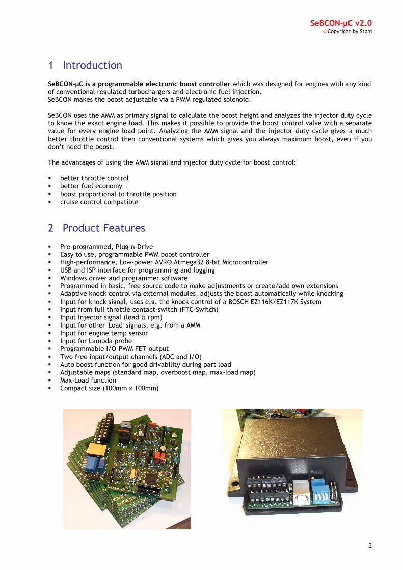
9.1.3 Open a logfile in Excel Start Excel, go to the menu ‘Data’ and choose ‘Import external data’ -> Import data. Choose your Test.txt file, search for the line number which looks like line 2321. Change the ‘Start import at row’ line to this line number and choose ‘next’.
In the next window select under ‘Delimiters’ the option ‘Semicolon’, then choose ‘Finish’.
SeBCON-µC v2.0 ©Copyright by Stoni
16
In the next window which looks like this, just choose ‘OK’.
The next window should look like this:

SeBCON-µC v2.0 ©Copyright by Stoni
17
Next step is to choose the chart wizard under the menu ‘Insert’ and ‘Chart’, then make the following changes: ‘Custom Types’ and Colored Lines, should look like this:
After a click on ‘Finish’ you should see a window like this:
You can resize the chart when you grab the chart at the edges.

SeBCON-µC v2.0 ©Copyright by Stoni
18
Full load in the 5th gear, 180 - 240Km/h
T=100ms: Interval between the measuring points is ~100ms
SOL%: Duty cycle (pulse width) in % of the solenoid Range: 0-100 (limited via software to 95%)
INJ%: Duty cycle (pulse width) in % of the injector signal Range: 0-100
RPMx100: Engine speed Range: 8-76 (825-7650rpm)
AMM%: Output voltage from the air mass meter Range: 47-100 (~2.5V-5.25V)
TEMP: Engine temperature Range: 0-120 (ballpark estimate, depends on the sensor)
FCUT: Fuel cut for the powershift option Range: 0 or 50, 0=no cut, 50=shutdown of the injectors
OB: Overboost Range: 107=no overboost, 109=overboost active, 105=overboost disabled
FTC: Full throttle contact Range: 102 inactive, 104=active
OD: Overdrive active Range: 0=disabled, 51= enabled
BC%: Boost correction in % Range: 100-0 , correction of the solenoids duty cycle in %
100=no correction, 96 e.g. = -4%, but only at the current rpm field!
LDA: Lambda probe voltage Range: 0-100 (0-1V)

SeBCON-µC v2.0 ©Copyright by Stoni
19
10 Electronic stuff and programming
10.1.1 Software update If you want to update the software or the maps, you can use either the USB channel or the ISP interface on your SeBCON, depends on your preferences. If you choose the USB interface, switch3 must be set to ‘ON’, to use the ISP interface switch3 must be set to ‘OFF’. If you choose the ISP Interface, which complies with the ATMEL ISP Interface for AVR’s, then I think that you will know very well how to proceed. A software update contains always 2 files, the xxx.bin file and the xxx.eep file. The bin file includes the program of the box; the eep file includes the maps. Both files can be uploaded separately, but in the case of an official software update both files must be uploaded with the same version! Assuming that you will use the USB channel you have to proceed as follows: For programming you need at least a 12V power source with 100mA which is connected to port 5(ground) and 6(plus). If your SeBCON is installed in your car, switch on the ignition and then connect the USB cable. Have a look into the folder c:\sebcon\software\; there you will see the file ‘Command Prompt’. Double-click on this file and you will get:
Type ‘dir’ and hit ‘enter’:
You can see the bin file ‘2.11.bin’ and the eep file ‘2.11.eep’. If you want to write the new files, both files must be placed in the folder c:\sebcon\software\.

SeBCON-µC v2.0 ©Copyright by Stoni
20
In case you want to upload a complete set of new software type at the command prompt: > sebcon -u filename In this example :> sebcon -u 2.11
That’s it. If you just want update your maps, then type: sebcon -e filename In this example :> sebcon -e 2.11
SeBCON-µC v2.0 ©Copyright by Stoni
21
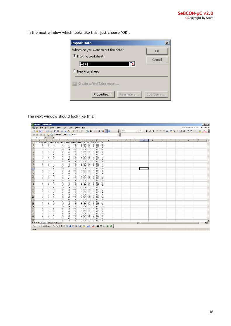
If you only want update your program and leave the old maps, then type: sebcon -f filename In this example :> sebcon -f 2.11
In case you want to make a backup of your current files which are in use, then type: sebcon -b
This will create the files ‘backup.bin’ and ‘backup.eep’ in the folder c:\sebcon\software\ If you want these files back on your SeBCON, then type: sebcon -wb

SeBCON-µC v2.0 ©Copyright by Stoni
22
If you want to see all available options, then type: ‘sebcon’ and ‘ftisp’
Be warned, never change something at the fuse bits, except you know exactly what you do, wrong fuse bit settings can lead to an unrecoverable loss of the microprocessor. In this case the only help will be a soldering iron and a new microprocessor! In case you need the correct fuse settings: sebcon fuse

SeBCON-µC v2.0 ©Copyright by Stoni
23
10.1.2 Bascom-AVR Do you have already downloaded and installed Bascom-AVR? Just use the link from section 8.1.1 and download the free available demo version, this version compiles files up to 4kb, enough to create new maps. If you want to make your own software bins, you need the full (licensed) version of Bascom-AVR. Start Bascom and open the file x.xx_maps.bas file from the original software, which you can download from my website, it will look like this:
The values is in %, normally a change of 10 points leads to an alteration in boost of ~1-2psi, but this depends mainly on the turbo you use. You can edit the values in the ‘Data’ lines; compile the new data by pressing ‘F7’. After this you will find a new x.xx_maps.eep file in your folder, copy this new x.xx_maps.eep file to c:\sebcon\software and update your SeBCON-µC with (see chapter 10.1.1): sebcon -e x.xx_maps

SeBCON-µC v2.0 ©Copyright by Stoni
24
10.1.3 New maps You will find 3 maps in the x.xx_maps.bas file, the Boostmap, the Overboostmap and the Maxloadmap. Boostmap = correction values in % for normal cruising over the complete power band. The map contains a correction value in % for the normal boost value which is primary calculated out of the amm signal. Normal values will be around 85-115. The default map will give you a continuously rising boost height over the rpm-band, just as you would drive an engine with high cylinder capacity. This is the map which modulates the primary boost curve. Overboostmap = correction values for the 8 sec overboost below 4500rpm Same as the above Boostmap with the difference that normal values will be around 100-130 and the values come in place if the rpm is above 4500rpm and the full throttle contact is active. Knocking or too high duty cycles from the injectors or the solenoid output will disable this map. Maxloadmap = fixed cycle time, this is a kind of torque control /limiter. The value states the maximum pulse width by a specified rpm for the solenoid, valid values are: 0:0% - 255:100% No other value can overwrite this settled limit. If the limiter is active, you will see this in the logfile. Normally the boost correction value ‘BC%’ will be 100 but if the boost correction is active, the value will be altered to a value below 100. You can see in the logfile by which rpm a correction has occurred. With this map it’s possible to program a maximum allowed ‘torque-curve’.
10.1.4 Technical data
Power supply:
� 11-16Volt � 100mA
Microprocessor:
� ATMEGA32-16AU � 14.7456 MHz
Interfaces:
� USB 2.0 � ISP In System Programming Interface � 4 external ADC channels (Port 8+9, C+D) � 1 external output channel 6 Amp. 10ns high switching speed (Port 4) � 1 external output channel 10 Amp. 100ns fast switching speed (Port A) � 2 external output channels 200mA (Port 10+11) � 2 external input channels (Port 7+12) � 1 external input channel via opto-coupler (Port 3) � 1 external I/O channel (Port B)

SeBCON-µC v2.0 ©Copyright by Stoni
25
10.1.5 Circuit layout
In this chapter you can see how the micro controller is connected to the output connectors; this makes it much easier to program other things.

SeBCON-µC v2.0 ©Copyright by Stoni
26

SeBCON-µC v2.0 ©Copyright by Stoni
27

SeBCON-µC v2.0 ©Copyright by Stoni
28
10.1.6 Internal signals
SeBCON-µC Signal Signal Signal Port
Connector description Type Range Port µC Type
1 rpm & load clock+pwm 0-200Hz 0-100% PA1 PA2 ADC
2 rpm (additional signal) clock 0-200Hz - PA1 - ADC
3 Programmable input voltage 5-15V - PB0 - I/O
4 Solenoid pwm 30Hz 0-100% PD4 - I/O
7 Knock signal voltage 0-12V - PB2 - I/O
8 Air mass meter signal voltage 0-5,25V - PA6 - ADC
9 Temperature signal voltage 0-5,25V - PA7 - ADC
10 Programmable output pwm + i/o ground - PD7 - I/O
11 Status lamp voltage ground - PB3 - I/O
12 FTC switch voltage ground - PA3 - ADC
A Programmable output pwm + i/o ground - PD5 - I/O
B PB1 – free i/o port - 0-5,25V - PB1 - I/O
C PA4 – free adc port - 0-5,25V - PA4 - ADC
D Lambda probe Voltage 0-1V - PA5 - ADC
11 Miscellaneous If you have created your own extension which is it worth to be included at the official website, whatever, feel free to contact me. Have fun with your SeBCON-µC and don’t forget to visit the SeBCON-µC website from time to time ☺