Embed Size (px)
Citation preview
MIT OpenCourseWare http://ocw.mit.edu
2.61 Internal Combustion Engines Spring 2008
For information about citing these materials or our Terms of Use, visit: http://ocw.mit.edu/terms.
SI Engine Mixture Preparation
1. Requirements 2. Fuel metering systems 3. Fuel transport phenomena 4. Mixture preparation during engine transients
5. The Gasoline Direct Injection engine
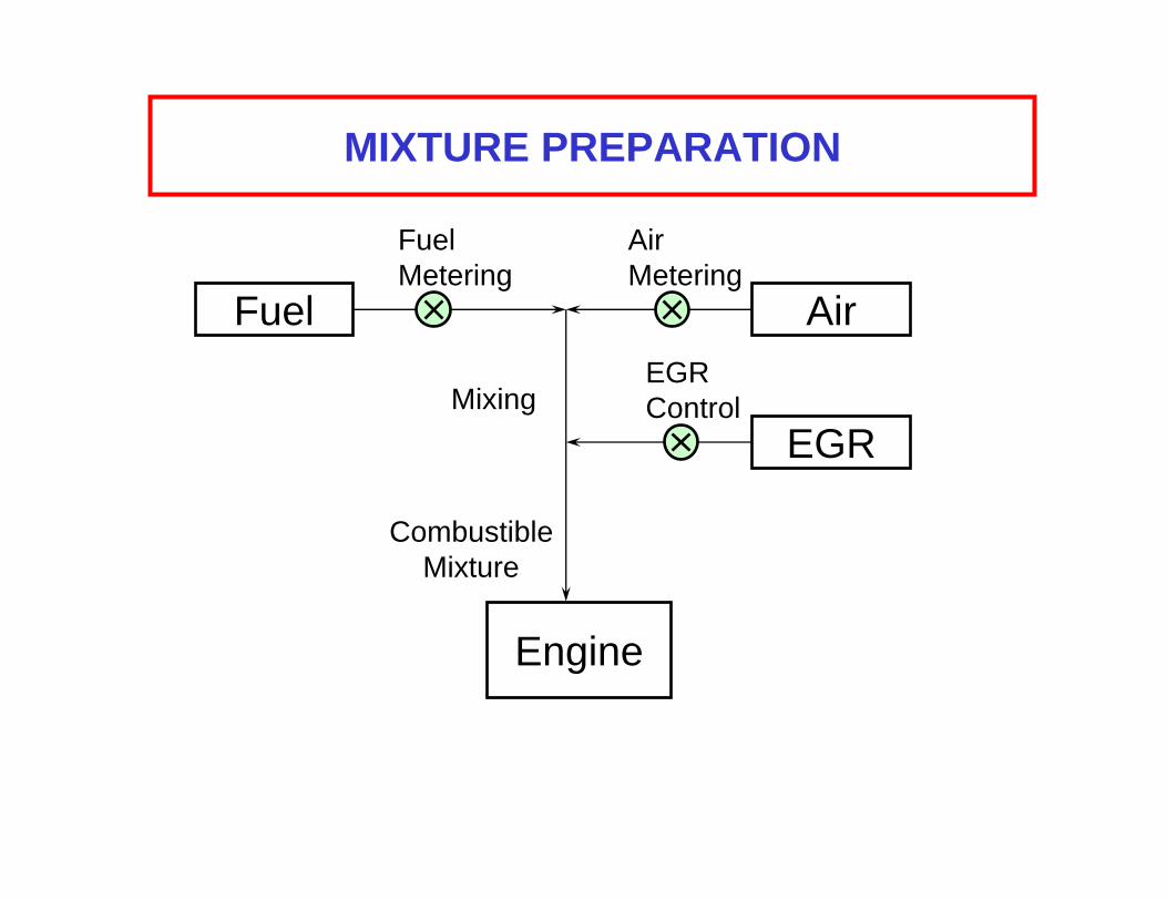
MIXTURE PREPARATION
Fuel
Fuel AirMetering Metering
Air EGR
Mixing Control EGR
Combustible Mixture
Engine
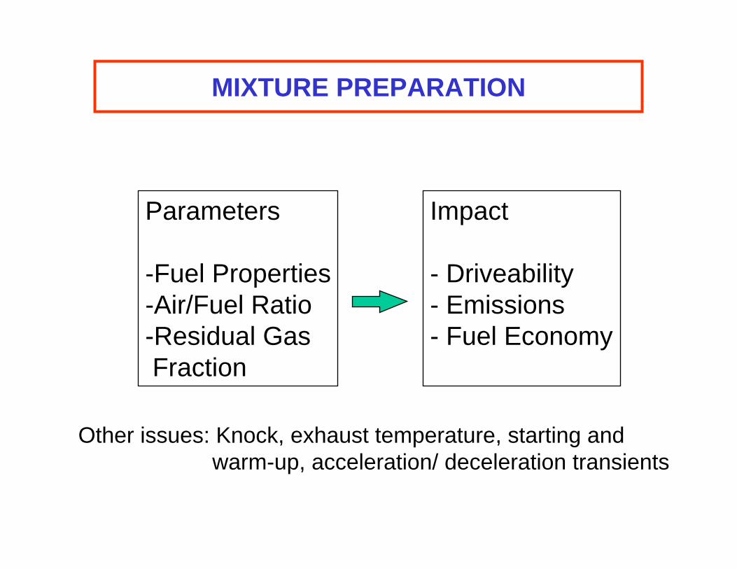
MIXTURE PREPARATION
Parameters Impact
-Fuel Properties - Driveability -Air/Fuel Ratio - Emissions -Residual Gas - Fuel Economy Fraction
Other issues: Knock, exhaust temperature, starting and warm-up, acceleration/ deceleration transients
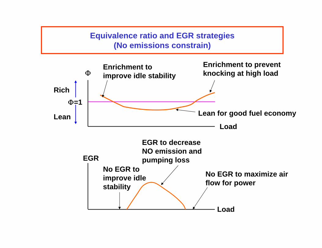
Equivalence ratio and EGR strategies(No emissions constrain)
Enrichment to Enrichment to prevent Φ improve idle stability knocking at high load
Rich Φ=1
Lean for good fuel economyLean Load
EGR to decrease NO emission and
EGR pumping lossNo EGR to No EGR to maximize airimprove idle flow for powerstability
Load
Requirement for the 3-way catalyst
Image removed due to copyright restrictions. Please see: Fig. 11-57 in Heywood, John B. Internal Combustion Engine Fundamentals. New York, NY: McGraw-Hill, 1988.
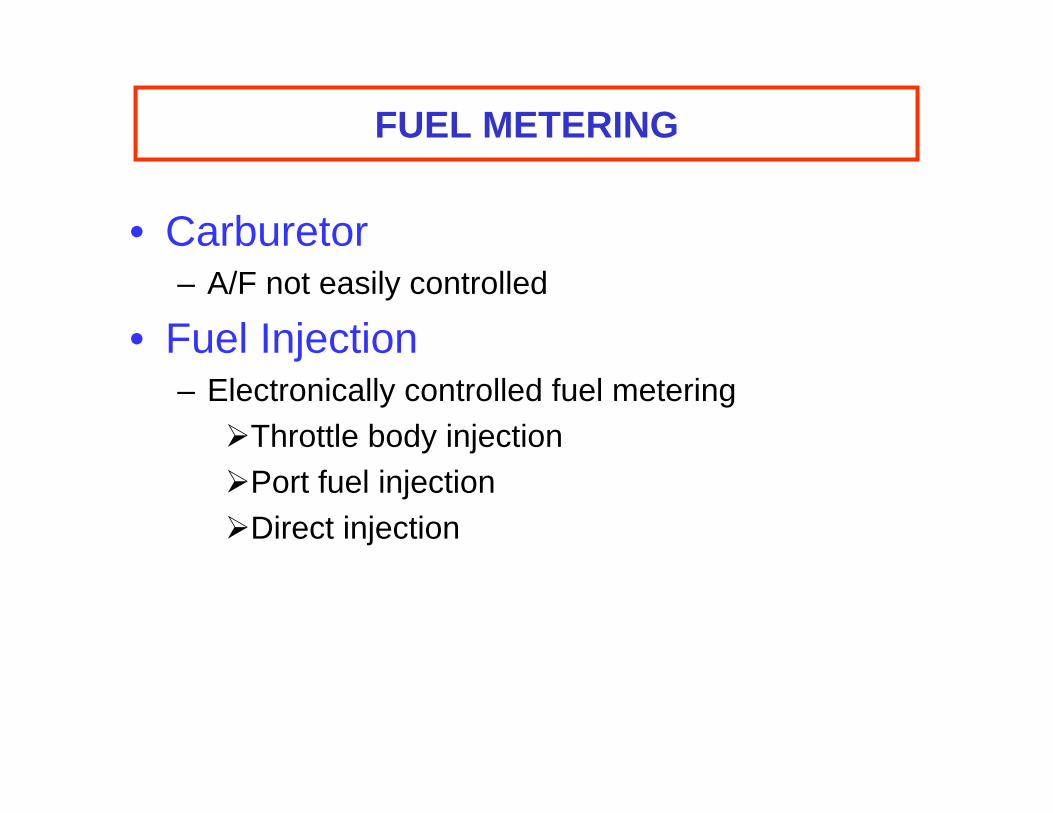
FUEL METERING
• Carburetor – A/F not easily controlled
• Fuel Injection – Electronically controlled fuel metering ¾Throttle body injection ¾Port fuel injection ¾Direct injection
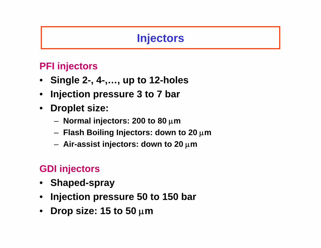
Injectors
PFI injectors • Single 2-, 4-,…, up to 12-holes • Injection pressure 3 to 7 bar • Droplet size:
– Normal injectors: 200 to 80 μm – Flash Boiling Injectors: down to 20 μm – Air-assist injectors: down to 20 μm
GDI injectors • Shaped-spray • Injection pressure 50 to 150 bar • Drop size: 15 to 50 μm
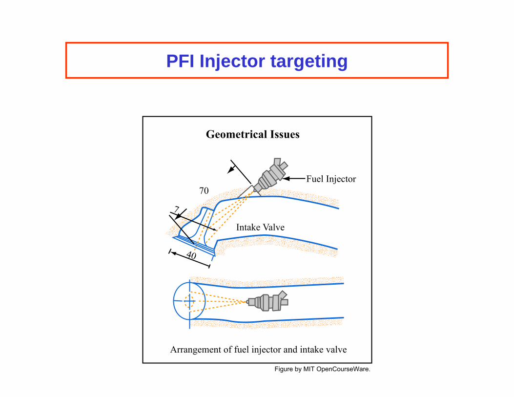
PFI Injector targeting
Fuel Injector
Intake Valve
70
7
40
Geometrical Issues
Arrangement of fuel injector and intake valve
Figure by MIT OpenCourseWare.
Engine management
system
From Bosch Automotive Handbook
Image removed due to copyright restrictions. Please see anyillustration of an engine control system, such as that in theBosch Automotive Handbook. London, England: John Wiley & Sons, 2004.
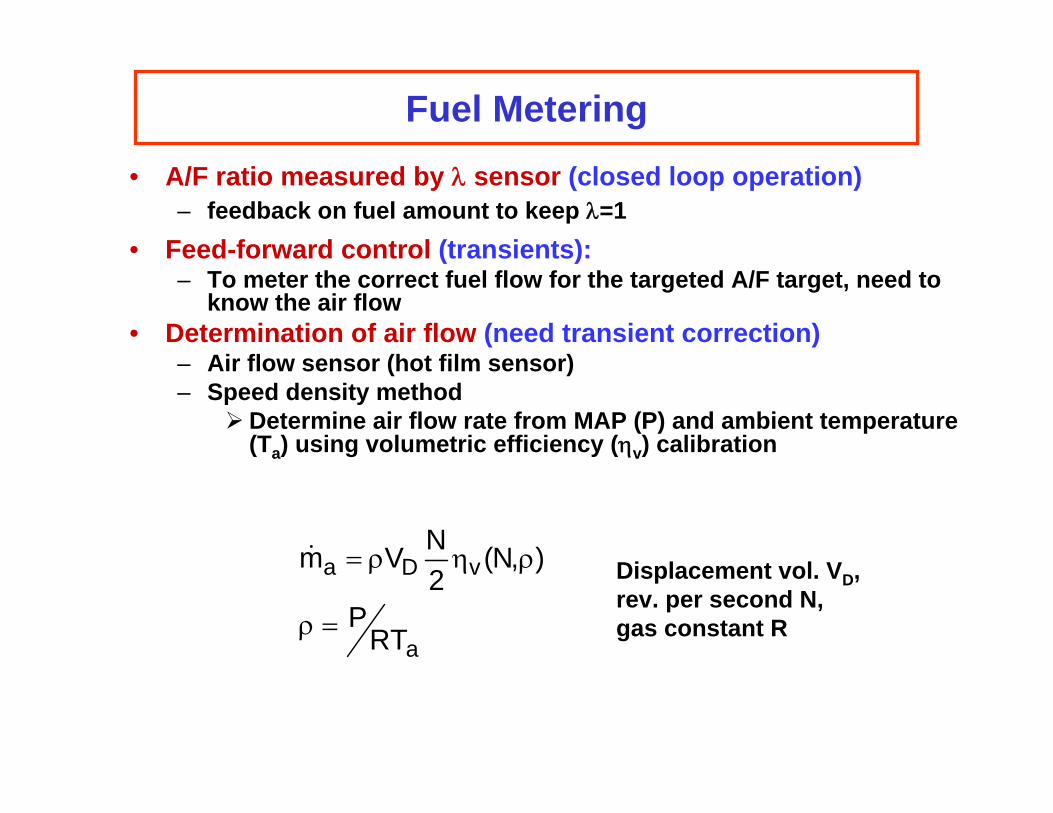
Fuel Metering
• A/F ratio measured by λ sensor (closed loop operation) – feedback on fuel amount to keep λ=1
• Feed-forward control (transients): – To meter the correct fuel flow for the targeted A/F target, need to
know the air flow • Determination of air flow (need transient correction)
– Air flow sensor (hot film sensor) – Speed density method ¾ Determine air flow rate from MAP (P) and ambient temperature
(Ta) using volumetric efficiency (ηv) calibration
N m� a = ρVD 2 ηv(N,ρ) Displacement vol. VD,
rev. per second N,ρ = PRTa
gas constant R
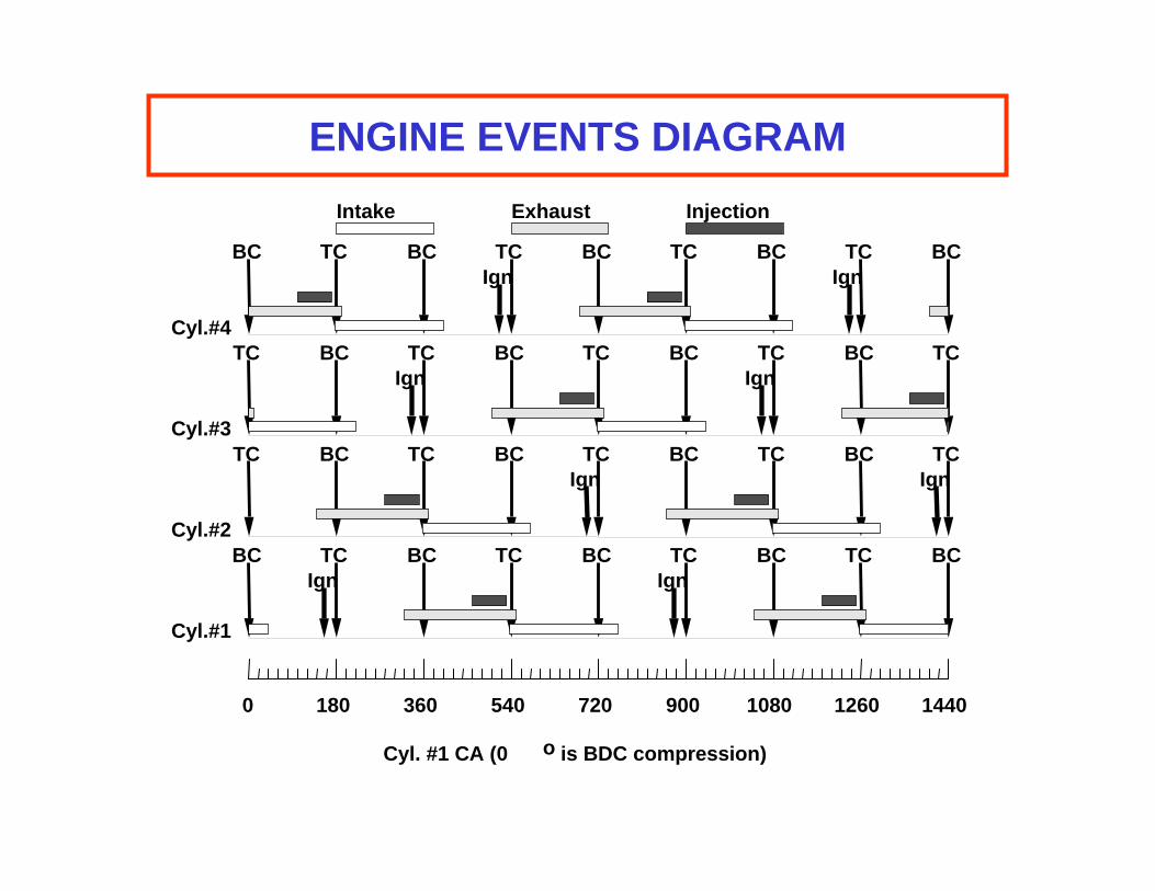
ENGINE EVENTS DIAGRAM
Intake Exhaust Injection
BC TC BC TC BC TC BC TC BC Ign Ign
Cyl.#4 TC BC TC BC TC BC TC BC TC
Ign Ign
Cyl.#3 TC BC TC BC TC BC TC BC TC
Ign Ign
Cyl.#2 BC TC BC TC BC TC BC TC BC
Ign Ign
Cyl.#1
0 180 360 540 720 900 1080 1260 1440
Cyl. #1 CA (0 o is BDC compression)
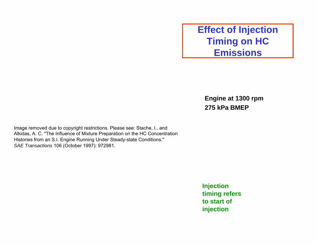
Effect of Injection Timing on HC
Emissions
Engine at 1300 rpm 275 kPa BMEP
Image removed due to copyright restrictions. Please see: Stache, I., andAlkidas, A. C. "The Influence of Mixture Preparation on the HC Concentration Histories from an S.I. Engine Running Under Steady-state Conditions." SAE Transactions 106 (October 1997): 972981.
Injection timing refers to start of injection
Mixture Preparation in PFI engine
Image removed due to copyright restrictions. Please see: Nogi, Toshiharu, et al. "Mixture Formation of Fuel Injection Systems in Gasoline Engines." SAE Transactions 97 (February 1988): 880558.
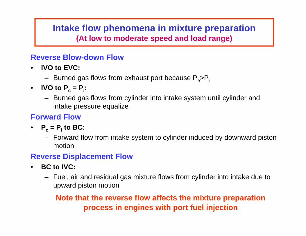
Intake flow phenomena in mixture preparation(At low to moderate speed and load range)
Reverse Blow-down Flow • IVO to EVC:
– Burned gas flows from exhaust port because Pe>Pi
• IVO to Pc = Pi: – Burned gas flows from cylinder into intake system until cylinder and
intake pressure equalize Forward Flow • Pc = Pi to BC:
– Forward flow from intake system to cylinder induced by downward piston motion
Reverse Displacement Flow • BC to IVC:
– Fuel, air and residual gas mixture flows from cylinder into intake due to upward piston motion
Note that the reverse flow affects the mixture preparation process in engines with port fuel injection
Mixture Preparation in Engine Transients
Engine Transients • Throttle Transients
– Accelerations and decelerations
• Starting and warm-up behaviors – Engine under cold conditions
Transients need special compensations because:
• Sensors do not follow actual air delivery into cylinder• Fuel injected for a cycle is not what constitutes the
combustible mixture for that cycle
Manifold pressure charging in throttle transient
Image removed due to copyright restrictions. Please see: Aquino, C. F. "Transient A/F Control Characteristics of the 5 Liter Central Fuel Injection Engine." SAE Transactions 90 (February 1981): 810494.
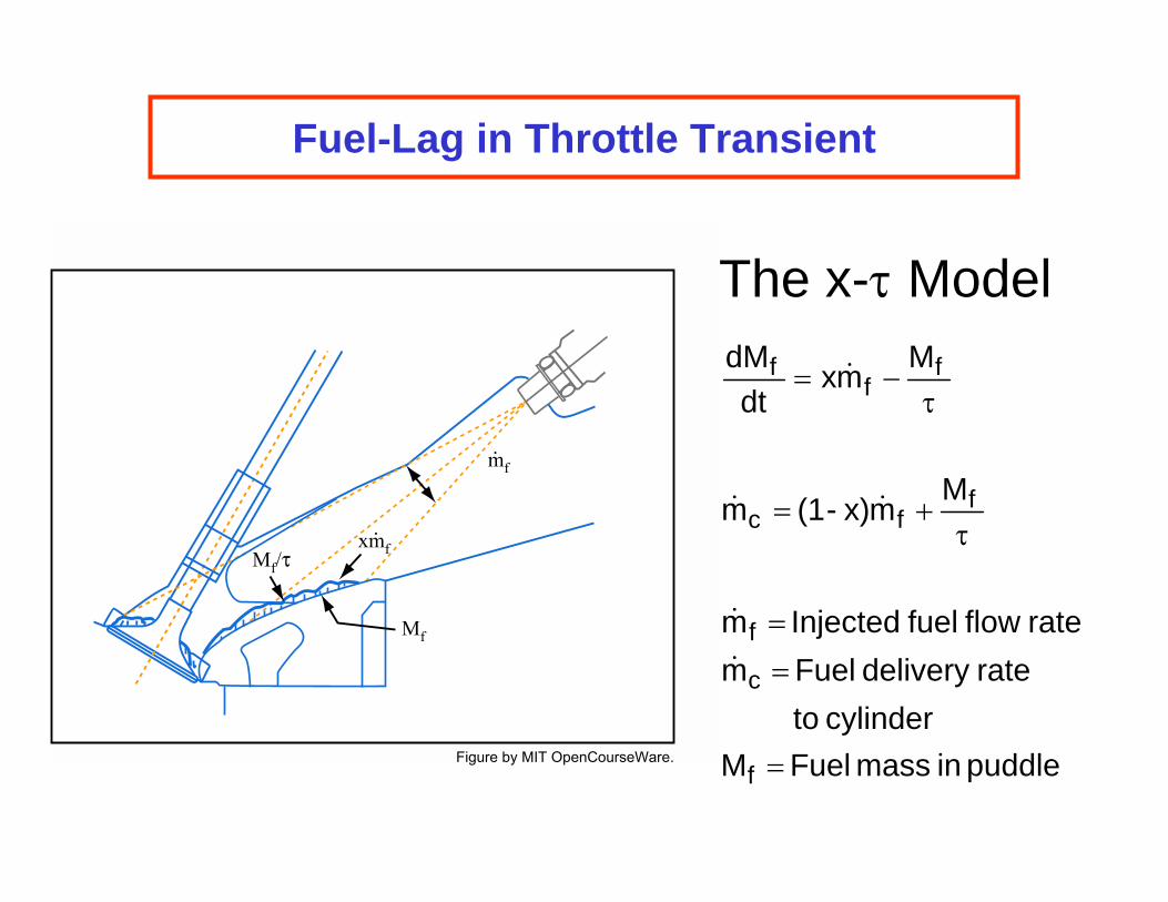
Fuel-Lag in Throttle Transient
The x-τ Model dMf = xm� f −
Mf dt τ
m� c = (1- x)m� f + Mf τ
m� f = Injected fuel flow rate m� c = Fuel delivery rate
to cylinder Mf = Fuel mass in puddle
mf.
xmf.
Mf/τ
Mf
Figure by MIT OpenCourseWare.
Fuel transient in throttle opening
Image removed due to copyright restrictions. Please see Fig. 7-28 in Heywood, John B. Internal Combustion Engine Fundamentals. New York, NY: McGraw-Hill, 1988.
Fig 7-28 Uncompensated A/F behavior in throttle transient
Engine start up behavior
2.4 L, 4-cylinder Image removed due to copyright restrictions. Please see: Fig. 1 in Santoso, Halim, and Cheng, Wai K. engine "Mixture Preparation and Hydrocarbon Emissions in the First Cycle of SI Engine Cranking." SAE Journal of Fuels and Lubricants 111 (October 2002): 2002-01-2805. Engine starts
with Cyl#2 piston in mid stroke of compression
Firing order 1-3-4-2
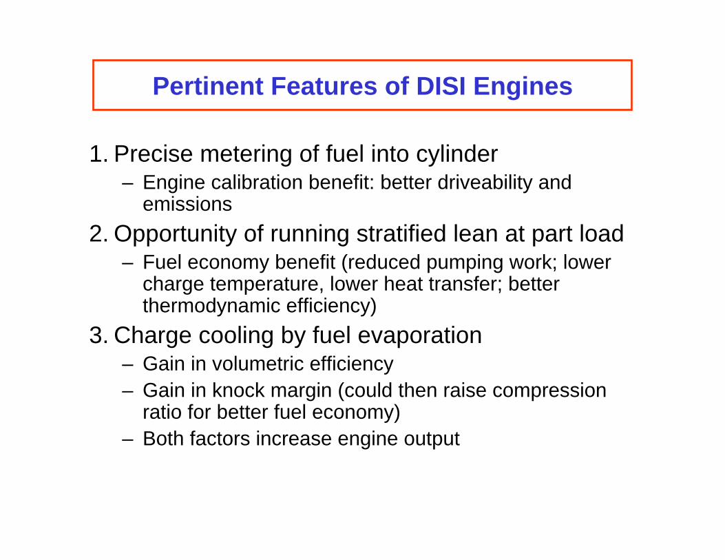
Pertinent Features of DISI Engines
1. Precise metering of fuel into cylinder – Engine calibration benefit: better driveability and
emissions 2. Opportunity of running stratified lean at part load
– Fuel economy benefit (reduced pumping work; lower charge temperature, lower heat transfer; betterthermodynamic efficiency)
3. Charge cooling by fuel evaporation – Gain in volumetric efficiency – Gain in knock margin (could then raise compression
ratio for better fuel economy) – Both factors increase engine output
Toyota DISI Engine (SAE Paper 970540)
Images removed due to copyright restrictions. Please see: Harada, Jun, et al. "Development of Direct-injection Gasoline Engine." SAE Journal of Engines 106 (February 1997): 970540.
Charge cooling by in-air fuel evaporation
Images removed due to copyright restrictions. Please see: Anderson, R. W., et al. "Understanding the Thermodynamics of Direct-injection Spark-ignition (DISI) Combustion Systems: An Analytical and Experimental Investigation." SAE Journal of Engines
105 (October 1996): 962018.
Full load performance benefit
Images removed due to copyright restrictions. Please see: Iwamoto, Y., et al. "Development of Gasoline Direct Injection Eengine." SAE Journal of Engines 106 (February 1997): 970541.
Part load fuel economy gain
Images removed due to copyright restrictions. Please see Kume, T., et al. "Combustion Control Technologies for Direct Injection SI Engine." SAE Journal of Engines 105 (February 1996): 960600.
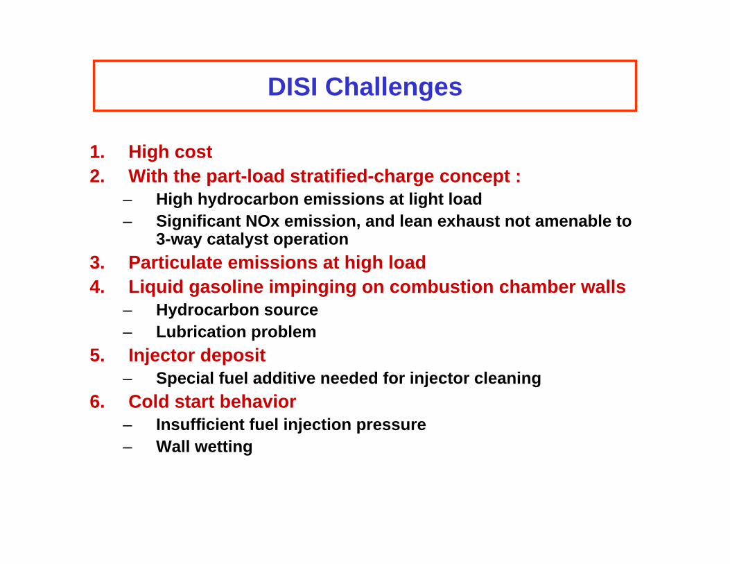
DISI Challenges
1. High cost 2. With the part-load stratified-charge concept :
– High hydrocarbon emissions at light load – Significant NOx emission, and lean exhaust not amenable to
3-way catalyst operation 3. Particulate emissions at high load 4. Liquid gasoline impinging on combustion chamber walls
– Hydrocarbon source – Lubrication problem
5. Injector deposit – Special fuel additive needed for injector cleaning
6. Cold start behavior – Insufficient fuel injection pressure – Wall wetting