Embed Size (px)
Citation preview
25 October 2005 - Run IIb Director’s Review
Alan L. Stone - Univ. of Illinois - Chicago
1
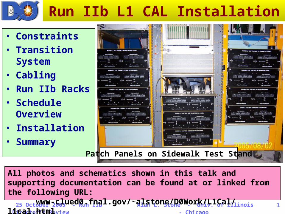
Run IIb L1 CAL Installation
• Constraints• Transition
System• Cabling• Run IIb Racks• Schedule
Overview• Installation• Summary
Patch Panels on Sidewalk Test Stand
All photos and schematics shown in this talk and supporting documentation can be found at or linked from the following URL:
www-clued0.fnal.gov/~alstone/D0Work/L1Cal/l1cal.html
25 October 2005 - Run IIb Director’s Review
Alan L. Stone - Univ. of Illinois - Chicago
2
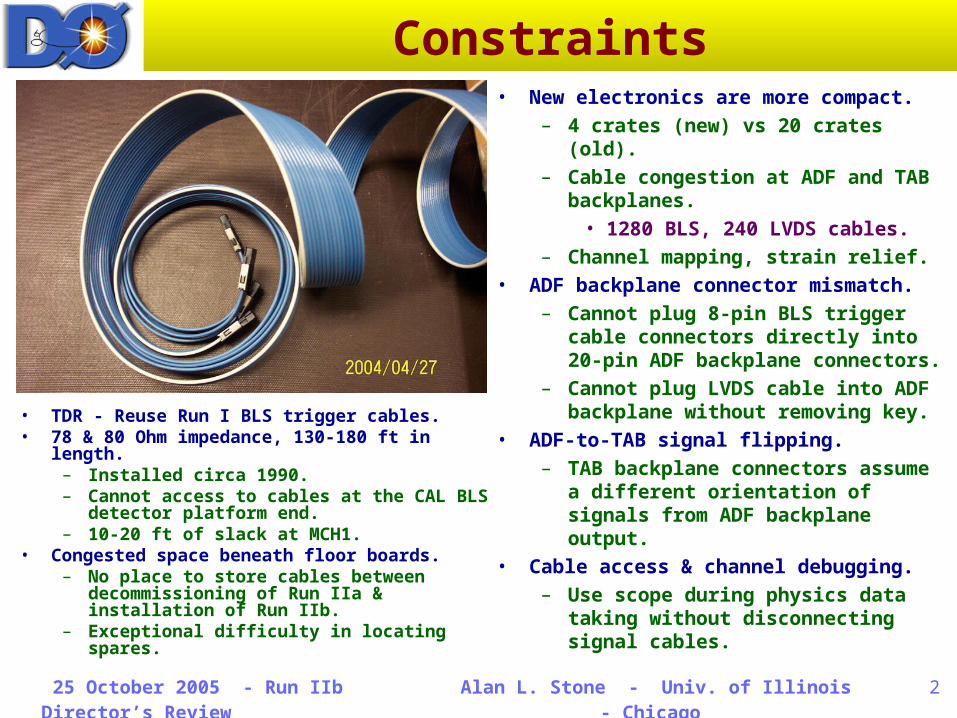
Constraints
• TDR - Reuse Run I BLS trigger cables.• 78 & 80 Ohm impedance, 130-180 ft in
length.– Installed circa 1990.– Cannot access to cables at the CAL
BLS detector platform end.– 10-20 ft of slack at MCH1.
• Congested space beneath floor boards.– No place to store cables between
decommissioning of Run IIa & installation of Run IIb.
– Exceptional difficulty in locating spares.
• New electronics are more compact.– 4 crates (new) vs 20 crates (old).– Cable congestion at ADF and TAB
backplanes.• 1280 BLS, 240 LVDS cables.
– Channel mapping, strain relief.• ADF backplane connector mismatch.
– Cannot plug 8-pin BLS trigger cable connectors directly into 20-pin ADF backplane connectors.
– Cannot plug LVDS cable into ADF backplane without removing key.
• ADF-to-TAB signal flipping.– TAB backplane connectors
assume a different orientation of signals from ADF backplane output.
• Cable access & channel debugging.– Use scope during physics data
taking without disconnecting signal cables.
25 October 2005 - Run IIb Director’s Review
Alan L. Stone - Univ. of Illinois - Chicago
3
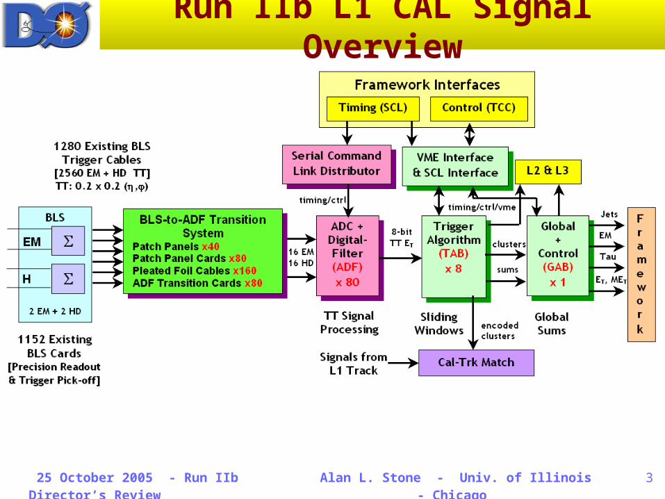
Run IIb L1 CAL Signal Overview
25 October 2005 - Run IIb Director’s Review
Alan L. Stone - Univ. of Illinois - Chicago
4
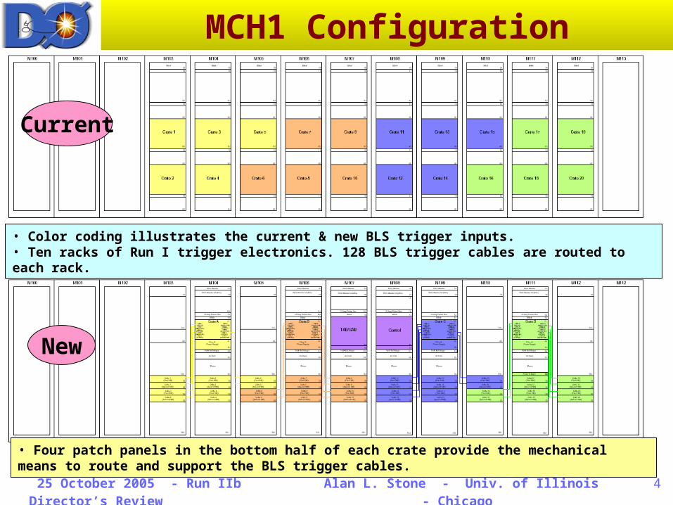
MCH1 Configuration
• Color coding illustrates the current & new BLS trigger inputs. • Ten racks of Run I trigger electronics. 128 BLS trigger cables are routed to each rack.
Current
New
• Four patch panels in the bottom half of each crate provide the mechanical means to route and support the BLS trigger cables.
25 October 2005 - Run IIb Director’s Review
Alan L. Stone - Univ. of Illinois - Chicago
5
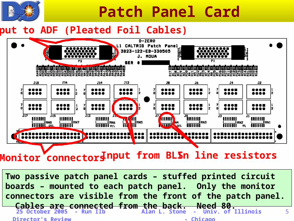
Patch Panel Card
Two passive patch panel cards – stuffed printed circuit boards – mounted to each patch panel. Only the monitor connectors are visible from the front of the patch panel. Cables are connected from the back. Need 80.
Output to ADF (Pleated Foil Cables)
Monitor connectorsInput from BLSIn line resistors
25 October 2005 - Run IIb Director’s Review
Alan L. Stone - Univ. of Illinois - Chicago
6
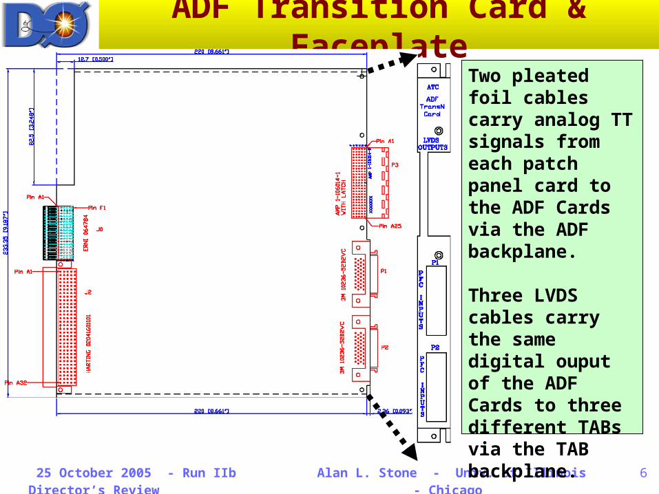
ADF Transition Card & Faceplate
Two pleated foil cables carry analog TT signals from each patch panel card to the ADF Cards via the ADF backplane.
Three LVDS cables carry the same digital ouput of the ADF Cards to three different TABs via the TAB backplane.
Need 80 ATCs.
25 October 2005 - Run IIb Director’s Review
Alan L. Stone - Univ. of Illinois - Chicago
7
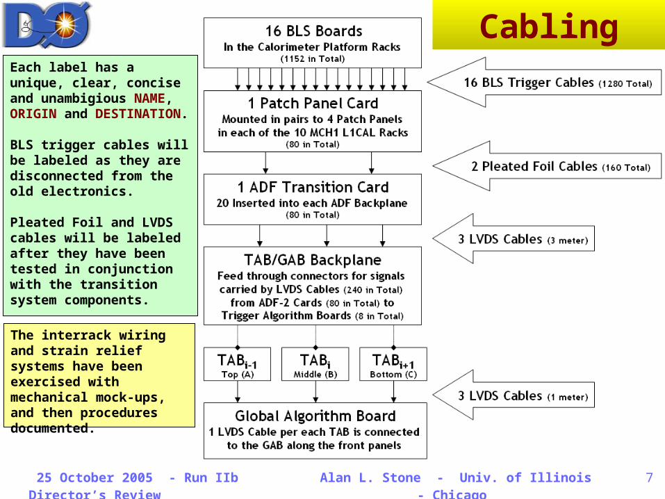
The interrack wiring and strain relief systems have been exercised with mechanical mock-ups, and then procedures documented.
Each label has a unique, clear, concise and unambigious NAME, ORIGIN and DESTINATION.
BLS trigger cables will be labeled as they are disconnected from the old electronics.
Pleated Foil and LVDS cables will be labeled after they have been tested in conjunction with the transition system components.
Cabling
25 October 2005 - Run IIb Director’s Review
Alan L. Stone - Univ. of Illinois - Chicago
8
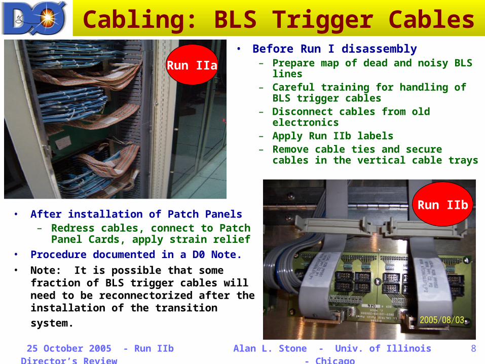
Cabling: BLS Trigger Cables• Before Run I disassembly
– Prepare map of dead and noisy BLS lines
– Careful training for handling of BLS trigger cables
– Disconnect cables from old electronics
– Apply Run IIb labels– Remove cable ties and secure
cables in the vertical cable trays
Run IIa
• After installation of Patch Panels– Redress cables, connect to Patch
Panel Cards, apply strain relief• Procedure documented in a D0 Note.• Note: It is possible that some
fraction of BLS trigger cables will need to be reconnectorized after the installation of the transition system.
Run IIb
25 October 2005 - Run IIb Director’s Review
Alan L. Stone - Univ. of Illinois - Chicago
9
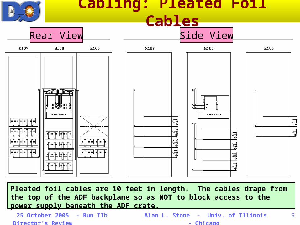
Cabling: Pleated Foil CablesRear View Side View
Pleated foil cables are 10 feet in length. The cables drape from the top of the ADF backplane so as NOT to block access to the power supply beneath the ADF crate.
25 October 2005 - Run IIb Director’s Review
Alan L. Stone - Univ. of Illinois - Chicago
10
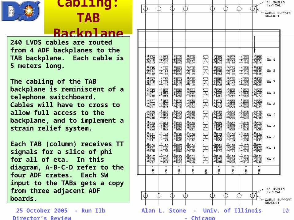
Cabling: TAB
Backplane240 LVDS cables are routed from 4 ADF backplanes to the TAB backplane. Each cable is 5 meters long.
The cabling of the TAB backplane is reminiscent of a telephone switchboard. Cables will have to cross to allow full access to the backplane, and to implement a strain relief system.
Each TAB (column) receives TT signals for a slice of phi for all of eta. In this diagram, A-B-C-D refer to the four ADF crates. Each SW input to the TABs gets a copy from three adjacent ADF boards.
25 October 2005 - Run IIb Director’s Review
Alan L. Stone - Univ. of Illinois - Chicago
11
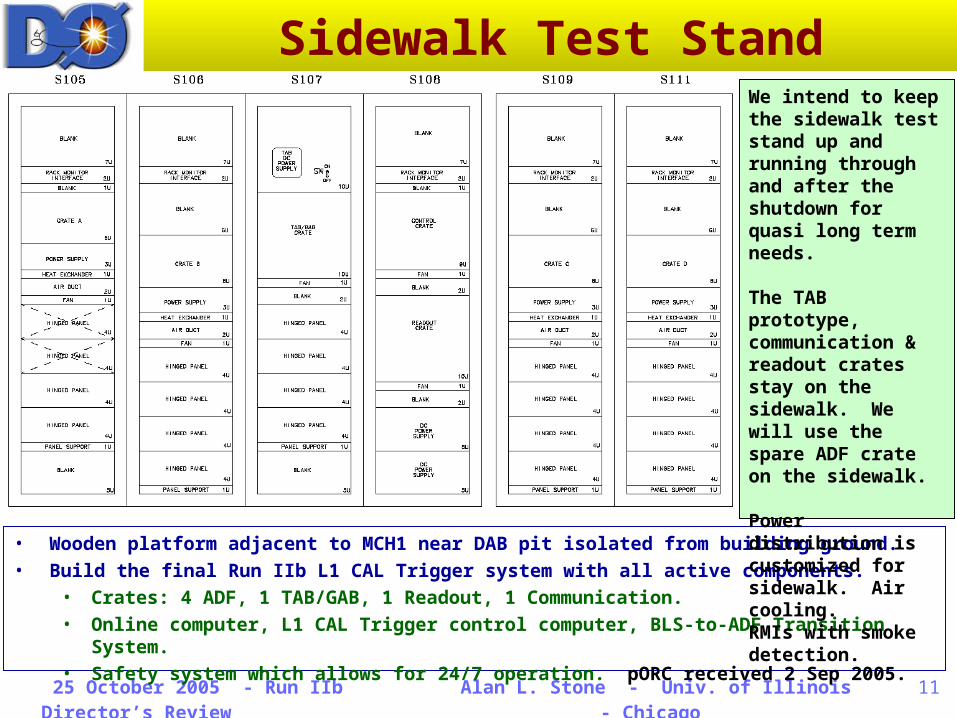
Sidewalk Test Stand
• Wooden platform adjacent to MCH1 near DAB pit isolated from building ground.• Build the final Run IIb L1 CAL Trigger system with all active components.
• Crates: 4 ADF, 1 TAB/GAB, 1 Readout, 1 Communication.• Online computer, L1 CAL Trigger control computer, BLS-to-ADF Transition
System.• Safety system which allows for 24/7 operation. pORC received 2 Sep 2005.
We intend to keep the sidewalk test stand up and running through and after the shutdown for quasi long term needs.
The TAB prototype, communication & readout crates stay on the sidewalk. We will use the spare ADF crate on the sidewalk.
Power distribution is customized for sidewalk. Air cooling.RMIs with smoke detection.
25 October 2005 - Run IIb Director’s Review
Alan L. Stone - Univ. of Illinois - Chicago
12
Pre-Installation• Sidewalk Test Stand
– Vertical slice of Run IIb signal path– Integrate into global readout
• Monitor Run IIb data with current trigger & physics readout
– 24/7 operation approved• Cabling
– Mock-up of BLS trigger cables• Very limited access before Run IIb
installation in MCH1– Interrack wiring & strain relief
drawings for Pleated Foil & LVDS cables done on sidewalk completed• Implement MCH1 procedures
– Run IIb labelling scheme• Transition System
– 1 Patch Panel Card, 2 Pleated Foil Cables, 1 ADF Transition Card, 3 LVDS Cables are tested as a unit (80 in total, plus spares)
– Only need full set of ATCs with LVDS cables for sidewalk operation• Finite set of BLS trigger inputs
– 12 Patch Panels assemblies on sidewalk• Remaining assemblies are in
DAB3, ready for shutdown
• Signal Electronics– Full set of ADF Crates & Boards
tested & in hand at D0, with spare set-up at MSU
– Full set of TABs & GABs at D0 • Communications & Readout
– Crates & Boards in hand at D0• Infrastructure
– Reuse MCH1 racks• Strip them to frames during
early weeks of shutdown– AC distribution boxes in hand
• Plugs directly into current MCH1 power
– Cooling systems• Commercial parts ordered
– Heat exchangers, hoses, valves
• Custom parts built at D0– Pipes, plenums
– RMIs, smoke detectors in hand– Custom cable support systems
• Bulkhead panel for L1CalTrk• Panels for BLS trigger cable
monitoring
25 October 2005 - Run IIb Director’s Review
Alan L. Stone - Univ. of Illinois - Chicago
13
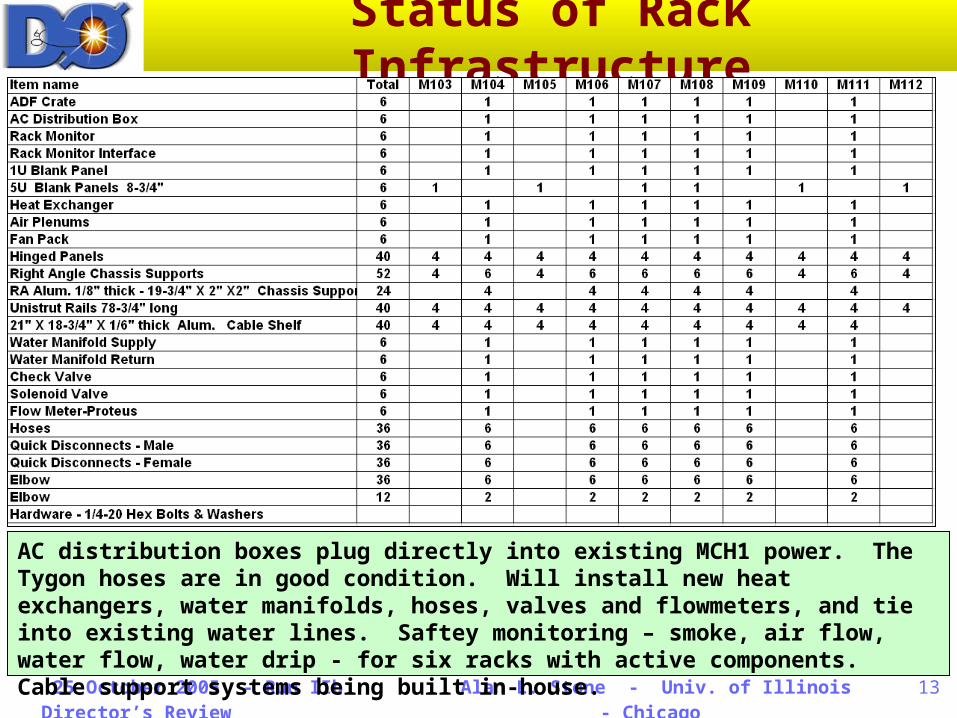
Status of Rack Infrastructure
AC distribution boxes plug directly into existing MCH1 power. The Tygon hoses are in good condition. Will install new heat exchangers, water manifolds, hoses, valves and flowmeters, and tie into existing water lines. Saftey monitoring – smoke, air flow, water flow, water drip - for six racks with active components. Cable support systems being built in-house.
25 October 2005 - Run IIb Director’s Review
Alan L. Stone - Univ. of Illinois - Chicago
14
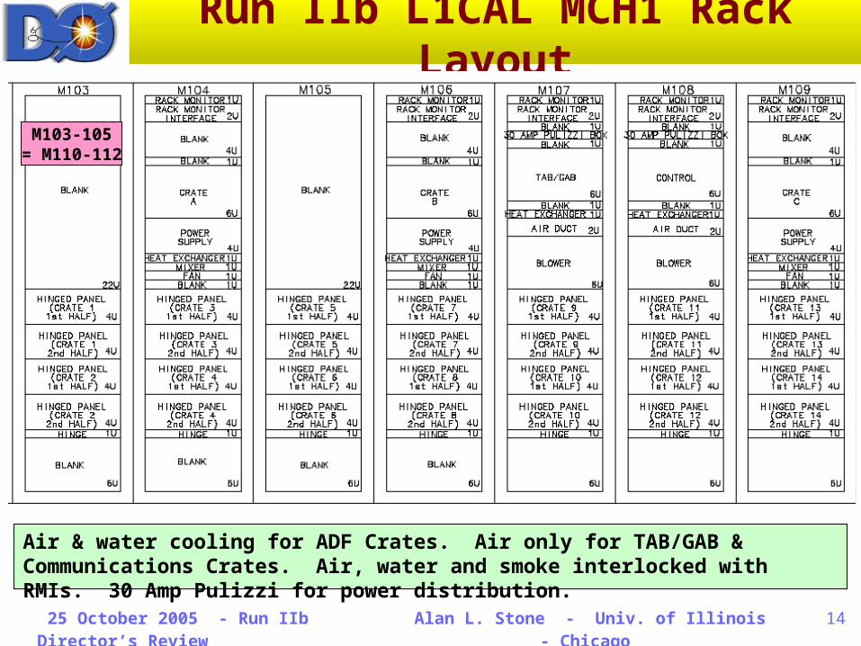
Run IIb L1CAL MCH1 Rack Layout
M103-105= M110-112
Air & water cooling for ADF Crates. Air only for TAB/GAB & Communications Crates. Air, water and smoke interlocked with RMIs. 30 Amp Pulizzi for power distribution.
25 October 2005 - Run IIb Director’s Review
Alan L. Stone - Univ. of Illinois - Chicago
15
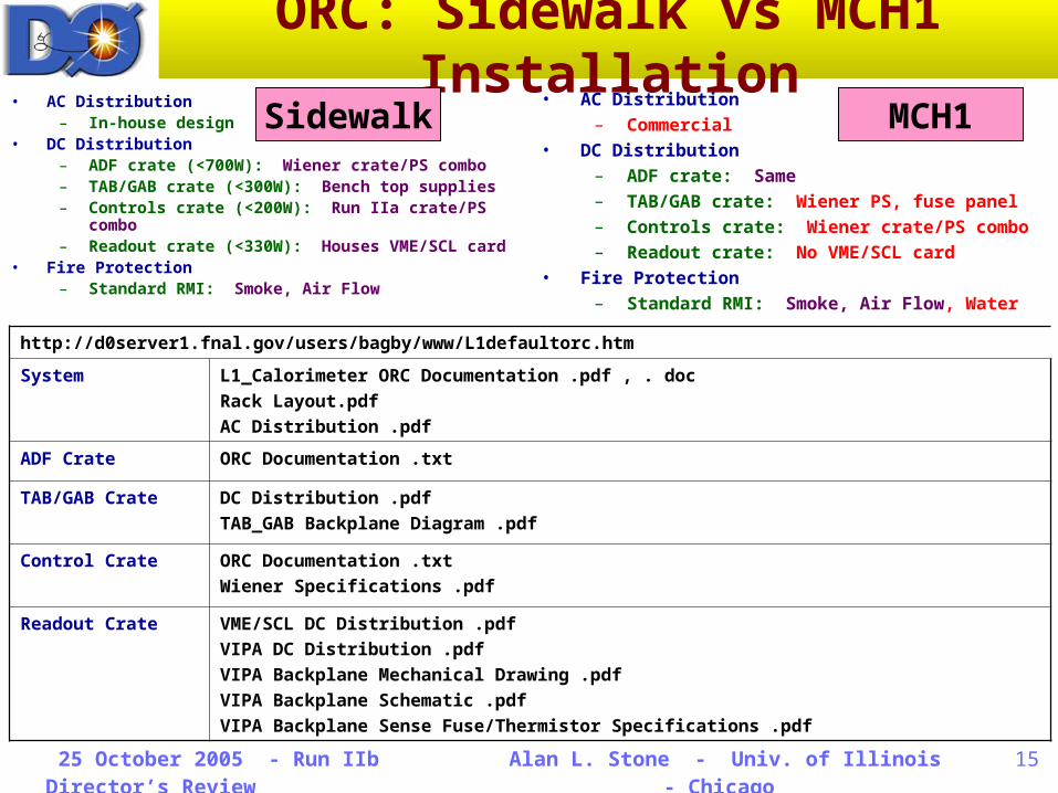
ORC: Sidewalk vs MCH1 Installation
• AC Distribution– In-house design
• DC Distribution– ADF crate (<700W): Wiener crate/PS combo– TAB/GAB crate (<300W): Bench top supplies– Controls crate (<200W): Run IIa crate/PS
combo– Readout crate (<330W): Houses VME/SCL
card• Fire Protection
– Standard RMI: Smoke, Air Flow
• AC Distribution– Commercial
• DC Distribution– ADF crate: Same– TAB/GAB crate: Wiener PS, fuse panel– Controls crate: Wiener crate/PS combo– Readout crate: No VME/SCL card
• Fire Protection– Standard RMI: Smoke, Air Flow, Water
http://d0server1.fnal.gov/users/bagby/www/L1defaultorc.htm
System L1_Calorimeter ORC Documentation .pdf , . docRack Layout.pdf AC Distribution .pdf
ADF Crate ORC Documentation .txt
TAB/GAB Crate DC Distribution .pdfTAB_GAB Backplane Diagram .pdf
Control Crate ORC Documentation .txt Wiener Specifications .pdf
Readout Crate VME/SCL DC Distribution .pdf VIPA DC Distribution .pdf VIPA Backplane Mechanical Drawing .pdf VIPA Backplane Schematic .pdf VIPA Backplane Sense Fuse/Thermistor Specifications .pdf
MCH1Sidewalk
25 October 2005 - Run IIb Director’s Review
Alan L. Stone - Univ. of Illinois - Chicago
16
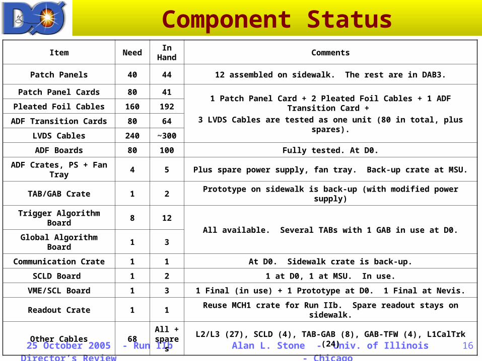
Component StatusItem Need
In Hand
Comments
Patch Panels 40 44 12 assembled on sidewalk. The rest are in DAB3.
Patch Panel Cards 80 411 Patch Panel Card + 2 Pleated Foil Cables + 1 ADF Transition
Card + 3 LVDS Cables are tested as one unit (80 in total, plus
spares).
Pleated Foil Cables 160 192
ADF Transition Cards 80 64
LVDS Cables 240 ~300
ADF Boards 80 100 Fully tested. At D0.
ADF Crates, PS + Fan Tray
4 5 Plus spare power supply, fan tray. Back-up crate at MSU.
TAB/GAB Crate 1 2Prototype on sidewalk is back-up (with modified power
supply)
Trigger Algorithm Board
8 12
All available. Several TABs with 1 GAB in use at D0.Global Algorithm
Board1 3
Communication Crate 1 1 At D0. Sidewalk crate is back-up.
SCLD Board 1 2 1 at D0, 1 at MSU. In use.
VME/SCL Board 1 3 1 Final (in use) + 1 Prototype at D0. 1 Final at Nevis.
Readout Crate 1 1Reuse MCH1 crate for Run IIb. Spare readout stays on
sidewalk.
Other Cables 68All + spares
L2/L3 (27), SCLD (4), TAB-GAB (8), GAB-TFW (4), L1CalTrk (24)
25 October 2005 - Run IIb Director’s Review
Alan L. Stone - Univ. of Illinois - Chicago
17
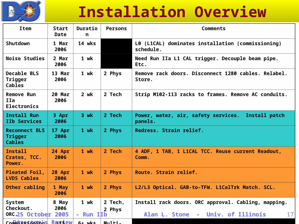
Installation OverviewItem Start
DateDuratio
nPersons Comments
Shutdown 1 Mar 2006
14 wks L0 (L1CAL) dominates installation (commissioning) schedule.
Noise Studies 2 Mar 2006
1 wk Need Run IIa L1 CAL trigger. Decouple beam pipe. Etc.
Decable BLS Trigger Cables
13 Mar 2006
1 wk 2 Phys Remove rack doors. Disconnect 1280 cables. Relabel. Store.
Remove Run IIa Electronics
20 Mar 2006
2 wk 2 Tech Strip M102-113 racks to frames. Remove AC conduits.
Install Run IIb Services
3 Apr 2006
3 wk 2 Tech Power, water, air, safety services. Install patch panels.
Reconnect BLS Trigger Cables
17 Apr 2006
1 wk 2 Phys Redress. Strain relief.
Install Crates, TCC. Power.
24 Apr 2006
1 wk 2 Tech 4 ADF, 1 TAB, 1 L1CAL TCC. Reuse current Readout, Comm.
Pleated Foil, LVDS Cables
28 Apr 2006
1 wk 2 Phys Route. Strain relief.
Other cabling 1 May 2006
1 wk 2 Phys L2/L3 Optical. GAB-to-TFW. L1CalTrk Match. SCL.
System Checkout. ORC.
8 May 2006
1 wk 2 Tech, 2 Phys
Install rack doors. ORC approval. Cabling, mapping.
Commissioning
>15 May 2006
6+ wks Multi-Physicists
25 October 2005 - Run IIb Director’s Review
Alan L. Stone - Univ. of Illinois - Chicago
18
Installation Comments• Some work can overlap.
– Staggered work over the full set of racks.
– Items with common color code on Slide 10.
• Schedules for various cabling is based on experience from performing mock-ups.– Procedures documented, and
pre-installation training is assumed.
• All durations assume one shift per day of either physicists or engineers.– May have two crews for some
tasks working in parallel• Constraints: Space, power
interruptions, noise– May have multiple shifts per
day to accelerate well-defined tasks• Constraints: Limited
expertise• L1 CAL upgrade has priority for
MCH activities during installation.
• Duration for stripping racks and installing services provided by John Anderson.– L1 CAL trigger upgrade will
have to draw from the same pool of resources for mechanical and electrical support.
– No engineer or technician is working 100% on L1 CAL.
– We are assuming that overtime will not be an option.
– A lot of advanced work is already done in building, ordering, and preparing all rack infrastructure.
• The next order of business is to assign names to each task.– We already have a good idea of
how much person power is needed.
– Complicated by shutdown delay.
– Premature to assign post-doc & grad student names to tasks planned for 6-8 months from now.
25 October 2005 - Run IIb Director’s Review
Alan L. Stone - Univ. of Illinois - Chicago
19
Installation Person Power• Decable & Label BLS Cables
– Two persons work as a team– 2 racks per day– Two teams can work in MCH1
at a time (physicists)• Remove Run IIa
– Remove boards, power supplies, heat exchangers, ribbon cables, airflow ductwork• Removal is faster as the
components do not need to be recovered
– Two persons work as a team• Technicians, but will need
engineering supervision– 1 rack per day– Two teams may work at
opposite ends of MCH1 at a time• But, may only have support
for one team per day• May require welder to cut
apart sub-crates
• Install Rack Infrastructure– Technicians, following engineering
designs and rack specifications• Estimate 1 rack per 2-3 days• 6 racks with services
– Patch panels can be installed by physicists (<1 week)
• Reconnect BLS Cables– Services are done from rear of rack,
BLS cables from front, possibility for overlap
– Same plan as “Decabling”• Crate Installation
– Transport from Sidewalk to MCH1– Connect to power– Strong backs– Could take only a day
• Other Cabling– Pleated Foil & LVDS Cabling similar
to BLS Cabling– Rest of system uses <100 cables
which can be routed & connected < 1 day• TFW, TAB-to-GAB, L2/L3,
L1CalTrk
25 October 2005 - Run IIb Director’s Review
Alan L. Stone - Univ. of Illinois - Chicago
20
Summary• Electronics in hand & tested
– All Crates & Boards• Transition System in hand
– Waiting for the final batch of production boards from vendors• < 2 weeks for remainder
– Testing will take about 2 weeks• Infrastructure ready
– All Power & Safety Services– Cabling: Routing & Support
Structures, Labels• Safety
– Sidewalk: pORC received Sep 2– MCH1: need approval about 8
weeks into shutdown• Docs nearly ready, submit in
advance for consideration• Documentation
– Labelling complete• Tested mechanically & with
software– Cable installation pending
• BLS decabling & recabling• PFC, LVDS routing & strain
relief
• Present Installation Schedule– Conservative with broad strokes
• Installation Features– Technician & engineering support
• Would benefit from someone working >30% on L1CAL
• Could accelerate decommissioning of current racks & installation of Run IIb services with overtime and/or extra person power (front-loaded)
– MCH1 decommissioning uncertainty• Not feasible to do a full mock-up• Original racks were built at MSU &
rolled as complete in early Run I– Detailed plan for BLS trigger cabling
• Careful training for anyone handling these cables
– List of dead & noisy channels • Final Installation Schedule
– Assign individual names to all tasks• Factor in university schedules
– Need daily breakdowns with Plan A & B• And multiple shifts, weekends
– Integrate with other systems• Run Coordinator, Calorimeter,
DAQ, Mechanical & Electrical Ops