Embed Size (px)
Citation preview
Available online at www.sciencedirect.com
Procedia Engineering 00 (2015) 000–000www.elsevier.com/locate/procedia
24th International Meshing Roundtable (IMR24)
Mesh generation for Atmospheric Boundary Layer simulation inwind farm design and management
A. Gargallo-Peiroa,∗, M. Avilaa, H. Owena, L. Prietob, A. Folcha
aDpt. Computer Applications in Science and Engineering, Barcelona Supercomputing Center, C/ Gran Capitan 2-4, 08034 Barcelona, SpainbEnergy Resource Dpt., Iberdrola Renovables Energıa, C/ Tomas Redondo 1, 28033 Madrid, Spain
Abstract
We propose a new automatic procedure to generate hybrid meshes to simulate turbulent flows for wind farm design and manage-ment. In particular, numerical modeling of wind farms involves a RANS simulation of the Atmospheric Boundary Layer (ABL)flow and modeling the turbines using the actuator disc theory. Therefore, the generated meshes have to fulfill several geometricalrequirements to answer to the different modeling features. They must: capture the topography features that can influence the windflow; have a boundary layer close to the terrain to resolve the ABL; be conformally adapted to the disc (turbine) to simulate theturbine effects on the wind flow; be adapted around the disc to capture the wake effect; and present a smooth mesh size transitionaround the disc to conform the mesh size of the ABL mesh, in which the turbines are immersed. We highlight that the mesh gen-eration procedure is fully automatic once given the mesh size, a topography description, the wind inflow direction, a list of turbineinsertion points, and the turbine models. To illustrate the applicability of the proposed procedure, we present two wind farm cases:an offshore wind farm mesh where we illustrate the computed wind deficit, and an onshore farm assimilating real topography data.c© 2015 The Authors. Published by Elsevier Ltd.Peer-review under responsibility of organizing committee of the 24th International Meshing Roundtable (IMR24).
Keywords: hybrid meshes, hexahedral meshes, quadrilateral meshes, mesh optimization, wind farm, wind turbine, atmospheric boundary layer
1. Introduction
In recent years, the advance in Computational Fluid Dynamics (CFD) techniques and the increase of the computingpower have widened the spectrum of engineering and industrial applications where numerical analysis can be applied.One paradigmatic example is wind industry, which relies on commercial (or in-house) CFD codes and parallel comput-ing for the design and management of wind farms in terms of power production. Numerical modeling of wind farmsinvolves the resolution of a turbulent flow immersed in the Atmospheric Boundary Layer (ABL) and considering theeffect of wind turbines, which produce a wind speed (power) deficit and increase turbulence downstream.
From the mesh generation point of view, each feature of the modeling presents different geometric requirements.First, for onshore farms it is necessary to mesh the terrain and its roughness to properly capture their effects on the flow.Second, wind turbines are immersed in the Atmospheric Boundary Layer, which poses mesh resolution and stretching
∗Corresponding author. Tel.: +34-93-401-6752.E-mail address: [email protected]
1877-7058 c© 2015 The Authors. Published by Elsevier Ltd.Peer-review under responsibility of organizing committee of the 24th International Meshing Roundtable (IMR24).

2 A. Gargallo-Peiro et al. / Procedia Engineering 00 (2015) 000–000
requirements to the CFD solvers. Third, the effects of wind turbines are typically simulated using an actuator discmodel, which has to be discretized in the mesh generation procedure. Moreover, in order to accurately predict thewind deficit induced by each turbine and its interaction with neighboring turbines, the computational mesh aroundand downstream of a turbine must be properly prescribed to capture the wake effects. All these aspects have a directimpact on the computational efficiency and simulation accuracy.
In general, CFD solvers used by industry make use of structured meshes of hexahedra which, when introducingdiscs require higher mesh resolution zones that propagate through the domain, increasing dramatically the number ofcomputational cells (nodes). In addition, simulations under different wind inflow angles (needed for wind resourceassessment) imply time-consuming meshing and pre-processing operations that are rarely automatized. In this work,we aim at overcoming these drawbacks presenting a new procedure to automatically mesh wind farms. The pro-duced meshes are used to solve the Reynolds-Averaged Navier-Stokes (RANS) equations with a k-ε turbulence modeladapted to the Atmospheric Boundary Layer [1] and considering the effects of wind turbines under the actuator disctheory, which introduces a sink in the momentum equations [2]. Both the mesh generation process and the solver areimplemented in the multi-physics parallel solver Alya [3,4].
The remainder of the paper is organized as follows. First, Section 2 presents several contributions relevant tothis work. Section 3 presents some preliminary notions that we will require to develop the proposed techniques.Next, Section 4 presents a procedure to generate hexahedral background meshes for Atmospheric Boundary Layersimulations assimilating real topography data, and Section 5 proposes a procedure to embed wind turbines leading toan hybrid conformal mesh. Finally, Section 6 shows two cases for onshore and offshore farms in order to illustrate theapplicability of the methodology.
2. Related work
In this work, we present a new method to generate hybrid conformal meshes of offshore and onshore wind farms.We divide the mesh generation procedure in two main steps. First, we generate a background wind mesh that repro-duces both the topography and the Atmospheric Boundary Layer. Second, we focus on generating a conformal meshadapted to the wind turbines features.
The generation of topography meshes with Atmospheric Boundary Layer has been classically approached fromthree main perspectives. Using Finite Volumes or Finite Differences, a structured grid is generated and the effectof the topography is introduced through a change of coordinates inside the formulation [5,6]. The second approach[7] exploits the advantages delivered by hexahedral elements to define boundary layers and proposed solving theThompson-Thames-Mastin equations [8], an elliptic system of partial differential equations, to determine the verti-cal configuration of a semi-structured mesh. Alternatively, tetrahedral meshes have also been used to focus on thediscretization of the topography in problems without boundary layer [9–11].
Following the second fashion, in this work we generate an hexahedral mesh conformal with the terrain and thatreproduces the desired boundary layer configuration. In particular, we base the procedure on an optimization frame-work to relocate the mesh nodes to obtain valid final meshes with the desired constraints. Note that in contrast withother hexahedral approaches, we use the optimization techniques to relocate the surface (and volume) nodes, beingable to obtain well-shaped elements (with uniform size) on the surface even when high-gradients of the terrain arepresent. To optimize both the surface and volume meshes, we use the continuous framework for high-order elementspresented in [12,13]. However, other applicable approaches can be used. For the surface case, different methods havebeen developed to optimize meshes on discrete surfaces [14–20] or using the parametric representation of a givensurface [21–24]. For volume meshes, several previous approaches have been developed to relocate the mesh nodesaccording to the optimization of a given quality measure [25–30].
The second contribution of this work is the generation of meshes for wind farm simulation. The standard procedureto model the effect of the turbines in a wind farm is using the actuator disc theory [31,32], where the turbine isrepresented with a disc. Mostly for offshore cases, the most common approach is the use of structured meshes withhigher resolution on the location of the turbine, where the elements that intersect with the actuator disc are assignedthe disc material properties [33–36]. Alternatively, in [37] it is presented a domain composition method where abackground mesh is coupled in a non-conformal manner with a mesh of each wind turbine. Herein, we generatefor each wind inflow direction a different hybrid mesh aligned with the wind direction and conformal with the wind
A. Gargallo-Peiro et al. / Procedia Engineering 00 (2015) 000–000 3
turbines. In contrast with previous work, we focus on obtaining a conformal mesh with the actuator disc that allowsus to prescribe the desired features around the disc without requiring to increase the resolution of the mesh in all thedomain.
3. Preliminaries and notation: quality measures for hybrid meshes
In this work, to determine the validity of a given mesh and to optimize it, we use a distortion (quality) measure thatquantifies the deviation of the mesh elements with respect to their desired configuration [38]. We denote the physicalelement by EP, and we name the element that represents the desired configuration by ideal element, EI . Herein,we use the mean ratio shape distortion measure, a Jacobian-based measure for simplexes presented in [39,40] thatquantifies the deviation of the shape of the physical element with respect to the ideal simplex:
η(DφE) =‖DφE‖
2
d |σ|2/d∈ [1,∞), (1)
where d is the spatial dimension, ‖ · ‖ is the Frobenius norm, σ is defined as det(DφE), and being
φE : EI −→ EP, (2)
an affine mapping between the ideal and physical simplices, and DφE its Jacobian with respect to the ideal coordinates.These measures assign η = 1 to the ideal element, and tend to ∞ as the element features (herein the element shape)degenerate. The corresponding quality measure is defined as
q :=1η∈ [0, 1]. (3)
To deal with inverted elements (σ ≤ 0), and specially to untangle meshes in the optimization procedure, we use theregularization of the determinant σ proposed in [29]. This regularization can be applied to Jacobian-based distortionmeasures where the determinant of the Jacobian appears in the denominator. Specifically, we replace σ in Equation(1) by
σδ(σ) =12
(σ +√σ2 + 4δ2
), (4)
where δ is a numerical parameter that has to be determined [24,29]. Using Equation (4) in (1), we obtain the regular-ized shape distortion measure,
ηδ(DφE) =‖DφE‖
2
d |σδ|2/d. (5)
In contrast with simplexes, given a quadrilateral, an hexahedron or a pyramid, the mapping φE is not affine, andtherefore, DφE(y) is not constant for y ∈ EI . Therefore, following references [12,13,41] we consider the regularizeddistortion measure presented in Eq. (5) as a point-wise distortion measure at y ∈ EI :
MφE(y) := ηδ(DφE(y)
). (6)
We point out that MφE is a function of y, and that it also depends on the element nodes x1, . . . , xnp (being np = 4 forquadrilaterals, np = 5 for pyramids, and np = 8 for hexahedra), since φE does. Using the point-wise measure, theelemental measure for a non-simplicial element is
ηE(x1, . . . , xnp ) :=‖MφE‖EI
‖1‖EI, (7)
where ‖·‖EI is the L2 norm on the ideal element, and ‖1‖EI is the measure of the ideal element. Similarly to Eq. (3),we define the quality of a non-simplicial element as the inverse of its distortion, Eq. (7).
4 A. Gargallo-Peiro et al. / Procedia Engineering 00 (2015) 000–000
(a) (b) (c)
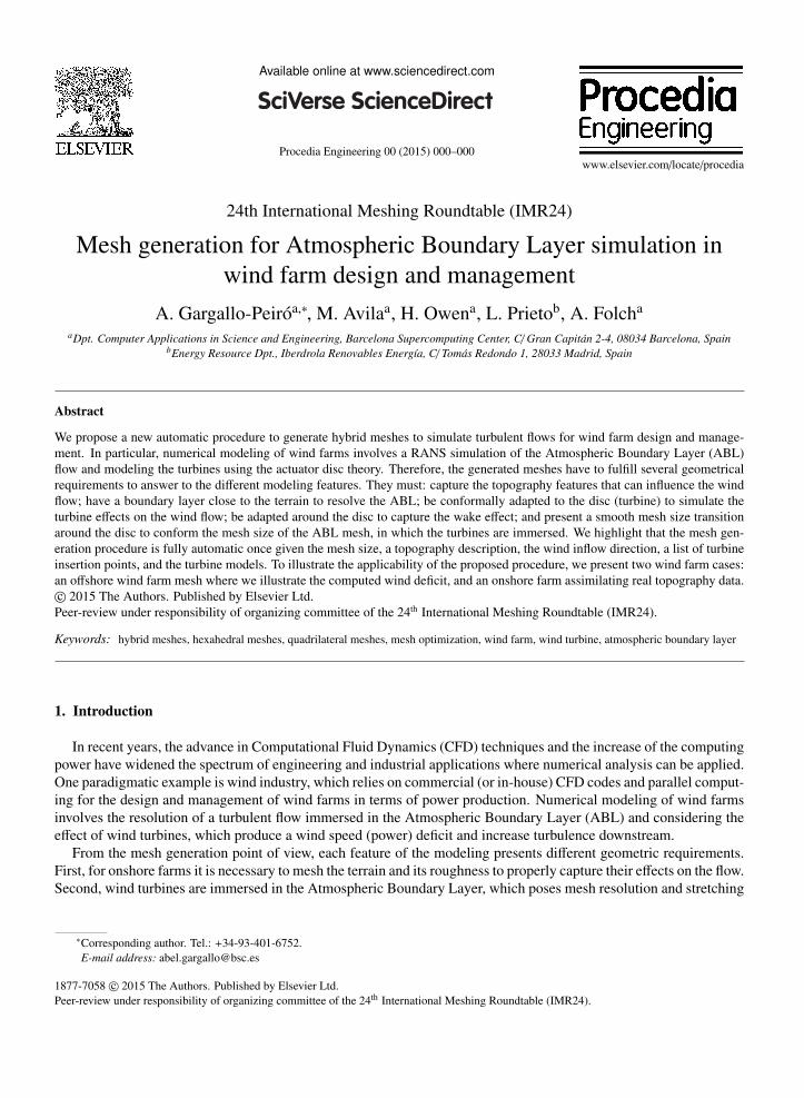
Figure 1. Mesh generation procedure on the Bolund peninsula (Denmark): (a) topography, (b) quadrilateral surface mesh, and (c) hexahedral windmesh.
4. Background wind mesh generation
To generate a mesh of the wind that is conformal with the turbines, herein, we first generate a background windmesh in which we will later insert the modeled turbines. Our domain is composed by a topography that defines thebottom surface, see Figure 1(a), and a planar top surface located in the desired height. The mesh generation procedureof the background wind mesh is composed by 2 steps, see Figure 1. First, we generate the topography quadrilateralsurface mesh, Figure 1(b), which is detailed in Section 4.1, and second, we generate the hexahedral wind mesh, Figure1(c), detailed in Section 4.2.
An important feature of the mesh generation process of a wind farm is that the turbines must be oriented againstthe wind, and that the mesh in downstream and upwind needs to be aligned with the wind direction. Since the finalturbine mesh will be oriented with the wind, the mesh generation procedure is already dependent on the wind direction.Therefore, we have chosen to focus on generating a background mesh aligned with the wind direction (hexahedra),instead of focusing on adapting it to the terrain (tetrahedra). We also highlight that we require highly stretchedelements on a ten-twenty percent of the domain in the vertical direction. Therefore, we generate an hexahedral windmesh taking advantage of the optimality of hexahedra to be aligned in the desired direction and also to define theAtmospheric Boundary Layer. Moreover, another important feature of hexahedra is that they fill with less elementsthe space, which is relevant in wind farm simulation, since we will deal with extensive domains.
4.1. Topography quadrilateral mesh generation
The final objective of the produced meshes is to simulate a given wind farm with real topography data. Theincoming topography is given in different formats (point cloud, Cartesian grid, contour topographic map...) that aretranslated into a triangular mesh which is used as an STL geometry representation. Given a point in the plane, it ismapped to the topography by means of finding to which triangle it belongs and interpolating its location in the triangle.Moreover, since the parameterization is defined from real data with noise (that comes both from the real topography,and also from the extraction technique) that we want to remove from the topography mesh, we perform several stepsof the signal processing smoothing method presented in [42–44].
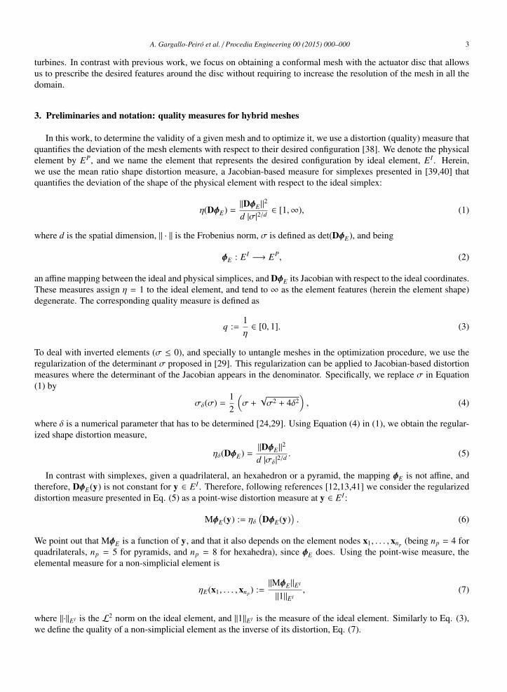
The generation of the topography mesh is composed by two steps. First, we generate an initial quadrilateral meshof the topography. Given a characteristic wind direction, we generate a structured quadrilateral mesh on the planealigned with this direction. Next, the nodes are mapped to the exact topography, defining a surface mesh. Notethat this mesh can be highly distorted, since elements that were square in the plane can be mapped to degeneratedconfigurations when there are high gradients in the topography, see Figure 2(a).
Second, we optimize the surface mesh. For each element on the surface, we consider as its ideal the correspondingelement in the plane. That is, we would like that each element on the surface (which nodes are constrained to thetopography), reassembles as much as possible the corresponding element generated initially on the plane. Using thisideal mesh and the point-wise distortion measures presented in Section 3, we derive an optimization procedure thatrelocates the nodes on the exact topography minimizing the mesh distortion.
To optimize the nodes on the exact topography, we use the surface parameterization (in our case, a discrete param-eterization) to express the distortion on a given point of the mesh in terms of the parametric coordinates of the nodes
A. Gargallo-Peiro et al. / Procedia Engineering 00 (2015) 000–000 5
(a) (b)
Figure 2. Quadrilateral generation procedure on the Bolund peninsula (Denmark): (a) initial surface mesh, and (b) optimized surface mesh. Themesh elements are colored with respect to their quality.
Table 1. Shape quality statistics for the quadrilateral meshes presented in Figure 2.
Mesh Min. Q. Max. Q. Mean. Q. Std. Dev.
Fig. 2(a) 0.35 1.00 0.99 0.02Fig. 2(b) 0.69 1.00 0.99 0.01
[12,24,45]. In particular, letU be the parametric plane, and let Σ be the physical surface (topography). Denoting by
ϕ : U ⊂ R2 −→ Σ ⊂ R3
u 7−→ x
the surface parameterization, we rewrite the point-wise distortion at y ∈ EI as
MϕφE(y; u1, . . . ,unp ) := MφE(y;ϕ(u1), . . . ,ϕ(unp )) = MφE(y; x1, . . . , xnp ). (8)
We seek the location of the nodes such that provide an optimal mapping in terms of the distortion measure, thatis, such that MϕφE(y) = 1 for y in all the ideal elements . However, since the mesh is constrained to the topography,this constrain can not be achieved in general, and we impose it in the least-squares sense. That is, we want to find{u∗1, . . . ,u∗nNs
} ⊂ U such that:
{u∗1, . . . ,u∗nNs} = argmin
u1,...,unNs∈U
12
nEs∑e=1
‖MϕφEe− 1‖2EI
e, (9)
where nNs is the number of surface nodes, and nEs is the number of surface elements.Figure 2 illustrates the surface mesh generation procedure in the Bolund peninsula, and Table 1 shows the mesh
quality statistics. In Figure 2(a) we show the initial surface mesh, which has a minimum quality of 0.35, that cor-responds to elements located in areas where high gradients of the topography are present. In contrast, Figure 2(b)shows the optimized mesh, with a minimum quality that has been increased to 0.69, and where we can observe regularelements all over the domain.
4.2. Background wind hexahedral mesh generation
The wind hexahedral mesh is generated by means of the extrusion of the quadrilateral surface mesh. The allowedinterval to choose the growth factor in the boundary layer is [1.1, 1.2], and the standard anisotropy in the first layer is
6 A. Gargallo-Peiro et al. / Procedia Engineering 00 (2015) 000–000
of 1/50. For each layer, we get the current extrusion length and we compute the extruding directions of the nodes inorder to maximize the orthogonality of the hexahedra generated in the new layer. To do so, we use the pseudo-normalof a given loop of nodes [46,47]. Given a node x with neighboring nodes x0, . . . , xnL , where we consider xnL+1 ≡ x1,the pseudo-normal n is computed as
n :=∑nL
i=1 xi × xi+1
‖∑nL
i=1 xi × xi+1‖. (10)
The pseudo-normal is proved to define the plane such that if you project the polygon defined by the loop of nodes tothat plane, provides maximal projected area, see [46,47]. We highlight that we will blend the pseudo-normal with thevertical direction in order to enforce that the mesh grows towards the ceiling and that it arrives to the top orthogonallyto the planar ceiling.
For each generated physical element, we will also set its corresponding ideal hexahedron. The ideal is computed asthe hexahadron that results from getting the planar quadrilateral (from the initially generated 2D mesh) associated tothis hexahedron, and extruding it in the vertical direction using the growth factor corresponding to the layer in whichthis hexahedron is located. Hence, this ideal element is orthogonal and has the desired size and anisotropy. Using thisideal element, we will compute the distortion (quality) of the generated physical hexahedron, see Equations (7) and(3). After generating all the elements of each layer, we perform an optimization of the nodes which define invalid orlow quality elements. We find the generated low-quality elements, and we will get several levels of neighbors to givemore freedom to the low-quality elements to be improved (in this work we have used 3 levels). Keeping the rest ofthe mesh fixed, for each node belonging to this neighborhood we solve the non-linear local problem corresponding tominimizing the distortion of the neighboring elements of that node:
xi = argminxi∈R3
12
niE∑
e=1
‖MφEe− 1‖2EI
e, (11)
where niE is the number of elements adjacent to node xi, and where by e we denote the global id of the e-th neighbor
element of node xi.Once all the mesh is generated, we will perform a final global optimization of the volume mesh [13], relocating
the nodes to improve the mesh quality. We will fix the nodes on the boundary surfaces, since they are already optimalin this lower dimensional entities, and we will optimize the volumetric nodes in R3. Without lost of generality, wereorder the indexes of the nodes so that the free nodes are in the first nF indexes. Analogously to the surface case, Eq.(9), we solve the following non-linear least squares problem:
{x∗1, . . . , x∗nF} = argmin
x1,...,xnF ∈R3
12
nE∑e=1
‖MφEe− 1‖2EI
e, (12)
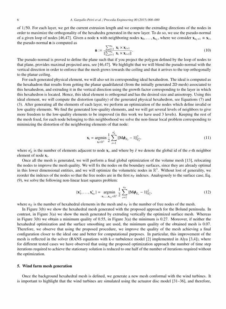
where nE is the number of hexahedral elements in the mesh and nF is the number of free nodes of the mesh.In Figure 3(b) we show the hexahedral mesh generated with the proposed approach for the Bolund peninsula. In
contrast, in Figure 3(a) we show the mesh generated by extruding vertically the optimized surface mesh. Whereasin Figure 3(b) we obtain a minimum quality of 0.55, in Figure 3(a) the minimum is 0.27. Moreover, if neither thehexahedral optimization and the surface smoothing are used, the minimum quality of the obtained mesh is 0.07.Therefore, we observe that using the proposed procedure, we improve the quality of the mesh achieving a finalconfiguration closer to the ideal one and better for computational purposes. In particular, this improvement of themesh is reflected in the solver (RANS equations with k-ε turbulence model [2] implemented in Alya [3,4]), wherefor different tested cases we have observed that using the proposed optimization approach the number of time stepiterations required to achieve the stationary solution is reduced to one half of the number of iterations required withoutthe optimization.
5. Wind farm mesh generation
Once the background hexahedral mesh is defined, we generate a new mesh conformal with the wind turbines. Itis important to highlight that the wind turbines are simulated using the actuator disc model [31–36], and therefore,
A. Gargallo-Peiro et al. / Procedia Engineering 00 (2015) 000–000 7
(a) (b)
Figure 3. Wind hexahedral meshes on the Bolund peninsula (Denmark). Mesh generated: (a) extruding in vertical direction, and (b) optimizing thevolume mesh. The volume elements are colored with respect to their quality, and each surface element is colored with respect to the quality of itsadjacent hexahedron.
Table 2. Shape quality statistics for the hexahedral meshes presented in Figure 3.
Mesh Min. Q. Max. Q. Mean. Q. Std. Dev.
Fig. 3(a) 0.27 1.00 0.99 0.03Fig. 3(b) 0.55 0.98 0.99 0.04
they are modeled as discs of a given width. Following the grid analysis performed in [34], we compute the width ofthe actuator disc as 0.06D, being D the disc diameter. To obtain the wind inflow direction of each wind turbine, wecan either use the initial condition of the velocity (offshore farms), previously calculated solving a 1D problem of theRANS equations over a flat and homogeneous ABL, or compute the direction adapted for each turbine by performingan initial simulation without turbines using the background mesh, and computing the wind direction in the location ofeach wind turbine (onshore farms).
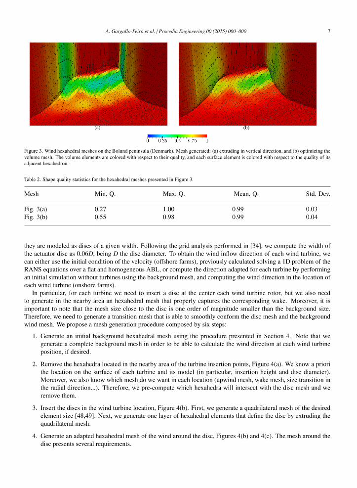
In particular, for each turbine we need to insert a disc at the center each wind turbine rotor, but we also needto generate in the nearby area an hexahedral mesh that properly captures the corresponding wake. Moreover, it isimportant to note that the mesh size close to the disc is one order of magnitude smaller than the background size.Therefore, we need to generate a transition mesh that is able to smoothly conform the disc mesh and the backgroundwind mesh. We propose a mesh generation procedure composed by six steps:
1. Generate an initial background hexahedral mesh using the procedure presented in Section 4. Note that wegenerate a complete background mesh in order to be able to calculate the wind direction at each wind turbineposition, if desired.
2. Remove the hexahedra located in the nearby area of the turbine insertion points, Figure 4(a). We know a priorithe location on the surface of each turbine and its model (in particular, insertion height and disc diameter).Moreover, we also know which mesh do we want in each location (upwind mesh, wake mesh, size transition inthe radial direction...). Therefore, we pre-compute which hexahedra will intersect with the disc mesh and weremove them.
3. Insert the discs in the wind turbine location, Figure 4(b). First, we generate a quadrilateral mesh of the desiredelement size [48,49]. Next, we generate one layer of hexahedral elements that define the disc by extruding thequadrilateral mesh.
4. Generate an adapted hexahedral mesh of the wind around the disc, Figures 4(b) and 4(c). The mesh around thedisc presents several requirements.

8 A. Gargallo-Peiro et al. / Procedia Engineering 00 (2015) 000–000
(a) (b)
(c) (d)
(e) (f)
(g)
Figure 4. Mesh generation process of the turbines as actuator discs for the test case of one turbine in the Sexbierum wind farm. (a) Backgroundwind mesh and hexahedral region to be removed. (b) Insertion of the disc mesh. (c) Wake and upwind mesh around the disc. (d) Transitionpyramids. (e) Transition filled with tetrahedra. (f,g) Final hybrid mesh. The elements are colored with respect to their element type (blue forhexahedra, green for tetrahedra, red for pyramids).
A. Gargallo-Peiro et al. / Procedia Engineering 00 (2015) 000–000 9
Table 3. Shape quality statistics for the hybrid mesh presented in Figure 4.
Mesh Min. Q. Max. Q. Mean. Q. Std. Dev.
Fig. 4(f) 0.15 1.00 0.94 0.08Hexahedra 0.70 1.00 0.96 0.01Tetrahedra 0.15 1.00 0.79 0.14Pyramids 0.79 1.00 0.89 0.09
• In the downstream direction we need to adapt the mesh size transition to capture the wake effects and tosmoothly match the background mesh size. Similarly, the transition in the upwind direction needs to besmooth. Ideally, when few turbines are present, we prescribe a size transition of 1.05, see [34]. However,in simulations with many turbines to avoid intersection of hexahedra due to the length of the imposedwake, a greater growth factor is automatically selected between 1.05 and 1.15 to shorten the downstreammesh and avoid intersections of the generated wake meshes for the different turbines.
• In the radial direction of each disc a mesh size transition is also required. In particular, since the turbineis immersed in the ABL, underneath the disc we need to decrease the mesh size (growth factor lower thanone), while in the center and top of the disc we need to increase the mesh size (growth factor greater thanone). Therefore, we automatically select the optimal number of radial element layers (typically betweentwo and five layers), and the different growth factors in each direction (in the range of [0.85, 1.15]) so thatthe mesh size transition is smooth.
5. Generate a transition layer of pyramids and tetrahedra, Figures 4(c) and 4(d). To match the background windmesh with the mesh around the disc, we get the last layer of hexahedra of both meshes and we split theminto tetrahedra and pyramids, using different templates depending on the shape and location of the originalhexahedra [50]. In particular, when a face has a neighboring hexahedron, a pyramidal element is generated,and when it has no neighbors (i.e. it faces the void between the background and disc meshes), new tetrahedralelements are formed.
6. Conform the inner and outer meshes with tetrahedra, Figure 4(e). To generate the tetrahedra to fill the gapbetween the two meshes we use the TetGen mesh generator [51].
The final mesh is illustrated in Figures 4(f) and 4(g). We highlight that in the procedure to generate the hybridmesh we do not perform any other optimizations than those provided by TetGen, since the background wind meshhas already been optimized and the mesh around the disc is generated imposing all the desired geometric properties.Therefore, both hexahedral meshes meet the desired requirements, and so the transition pyramid/tetrahedral layers do,since the transition is generated by means of splitting hexahedra that met the desired constraints. We take advantageof the flexibility of the Delaunay-based meshing provided by TetGen to fill the gap between the hexahedral meshes. Ifthe constraints to the tetrahedral mesh that must fill the void do not allow generating a valid mesh, we automaticallyremove additional layers of the background hexahedral mesh, until a final valid mesh is generated. In all the testedcases, it has only been necessary to remove one additional layer of hexahedra once.
Note that once the mesh is generated, we use the measures presented in Section 3 to compute the quality of allthe elements of the mesh and check their validity. It is important to remark that to define a quality measure of anelement, we need to set an ideal to this element. We know the ideal elements of the hexahedral mesh, and of thetransition tetrahedral/pyramidal elements of the boundary of the two hexahedral meshes. In particular, the ideals ofthe transition tetrahedron/pyramid elements are generated by applying the selected template to the ideal hexahedronthat corresponds to the physical transition hexahedron. However, we highlight that we also have to set the ideal of theTetGen tetrahedral elements. We have selected as ideal the equilateral tetrahedron, since TetGen is Delaunay-based.However, since the mesh is immersed in an atmospheric boundary layer, the tetrahedra close to the topography havethe desired anisotropy due to the constraints of the boundary surfaces (wake and backgound meshes). Hence, we

10 A. Gargallo-Peiro et al. / Procedia Engineering 00 (2015) 000–000
(a) (b)
Figure 5. Hybrid mesh on a wind farm on the Irish sea. The elements are colored with respect to their element type (blue for hexahedra, green fortetrahedra, red for pyramids).
Figure 6. Speedup of the wind due to the interaction with the wind turbines for the offshore wind farm presented in Figure 5.
know a priori that the quality values of these tetrahedral elements will be low although they have the desired shape.Therefore, the quality of the tetrahedral elements will be used specifically to determine if an element is valid (positiveJacobian, q > 0) or not (negative Jacobian, q = 0).
Figure 4 details all the steps of the mesh generation procedure for a reference turbine in the Sexbierum wind farm(Netherlands). Table 3 shows the quality statistics of the generated mesh. Note that the mesh is valid for computationalpurposes (q ≥ 0.15), and that we obtain a high-quality hexahedral mesh (q ≥ 0.7) with the desired features.
6. Wind farm test cases
In this section, we present the meshes generated for an offshore and an onshore wind farms. We highlight that thewhole mesh generation procedure is automatic once given the mesh size (size of the surface mesh and growth factor),a topography description, the wind inflow direction, a list of points where the turbines need to be inserted, and theturbine specifications (diameter and height).
Offshore wind farms. We present the mesh of a wind farm with 108 turbines located on the Irish sea. The generatedmesh is composed by 25.114.030 elements, from which 17.861.840 are hexahedra, 6.082.816 are tetrahedra, and1.169.374 are pyramids. Table 4 illustrates the quality statistics of the generated meshes. We can observe that similarlyto the Sexbierum case illustrated in the previous section, the quality of the hexahedral and pyramid elements is high(q > 0.7), but that the tetrahedra present lower quality values. However, the minimum quality is 0.11, and therefore,the mesh is valid for computational purposes. The mesh is generated in 301 seconds, including all the steps of theprocedure (background mesh, optimization and hybrid turbine mesh).
A. Gargallo-Peiro et al. / Procedia Engineering 00 (2015) 000–000 11
Table 4. Shape quality statistics for the hybrid mesh presented in Figure 5.
Mesh Min. Q. Max. Q. Mean. Q. Std. Dev.
Fig. 5 0.11 1.00 0.87 0.16Hexahedra 0.74 1.00 0.96 0.02Tetrahedra 0.11 1.00 0.75 0.19Pyramids 0.86 1.00 0.93 0.06
(a) (b)
Figure 7. Hybrid mesh on an onshore wind farm in Spain. The elements are colored with respect to their element type (blue for hexahedra, greenfor tetrahedra, red for pyramids).
Table 5. Shape quality statistics for the hybrid mesh presented in Figure 7.
Mesh Min. Q. Max. Q. Mean. Q. Std. Dev.
Fig. 7 0.10 1.00 0.87 0.13Hexahedra 0.53 1.00 0.95 0.03Tetrahedra 0.10 1.00 0.79 0.13Pyramids 0.77 0.99 0.96 0.08
Using Alya [3,4], a multi-physics parallel finite element solver, and the CFD model for wind farms presentedin [2], we compute the solution of the incompressible Reynolds-Averaged Navier-Stokes equations to illustrate theapplicability of the generated meshes. Figure 6 shows the wind speed deficit due to the effect of the turbines.
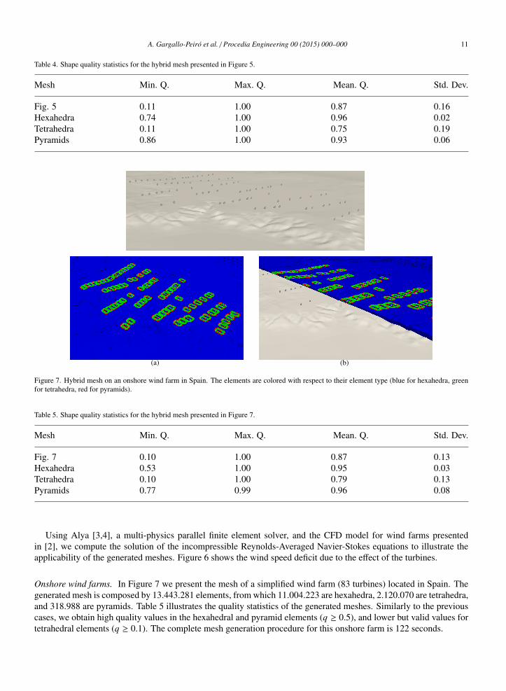
Onshore wind farms. In Figure 7 we present the mesh of a simplified wind farm (83 turbines) located in Spain. Thegenerated mesh is composed by 13.443.281 elements, from which 11.004.223 are hexahedra, 2.120.070 are tetrahedra,and 318.988 are pyramids. Table 5 illustrates the quality statistics of the generated meshes. Similarly to the previouscases, we obtain high quality values in the hexahedral and pyramid elements (q ≥ 0.5), and lower but valid values fortetrahedral elements (q ≥ 0.1). The complete mesh generation procedure for this onshore farm is 122 seconds.
12 A. Gargallo-Peiro et al. / Procedia Engineering 00 (2015) 000–000
7. Concluding remarks
In this work, we have presented a new mesh generation procedure for wind farm simulation. The proposed mesheris fully automatic and focuses on prescribing the desired geometrical features to simulate RANS equations immersedin the Atmospheric Boundary Layer, modeling the effect of the wind turbines using the actuator disc theory. Inparticular, given an inflow angle (wind direction), a mesh adapted to this direction is generated. First, we generatea background hexahedral mesh that resolves the Atmospheric Boundary Layer and captures the topography features.Second, we insert in the background mesh the turbines of the wind farm, in which the actuator disc model will apply.Specifically, for each turbine, it is mandatory to adapt the mesh around the disc and specially in the downstreamdirection in order to capture the wake effect and accurately calculate the wind speed (and energy) deficit that itinduces. Finally, to show the applicability of the developed approach, we show the resulting meshes on an offshoreand an onshore farms. In particular, to illustrate the validity of the meshes for computational purposes we also showthe wind speed deficit for the offshore farm.
We highlight that this is an ongoing work and that several features are to be developed in the near future. Onthe one hand, we want to explore the use of an unstructured surface mesh. In particular, we would like to comparethe current approach, where we focus on aligning the background mesh with the input inflow, with an unstructuredtriangle surface mesh (and a prismatic/tetrahedral volume mesh) that focuses on adapting to the topography. On theother hand, we are currently not performing any optimization of the hybrid mesh, and we would like to explore thepossibility of optimizing the final hybrid mesh to increase the quality of the tetrahedral elements.
Acknowledgements
We would like to thank to Iberdrola Renovables for their cooperation and the provided wind farm information,which have allowed us to test with real data the developed techniques.
References
[1] D. Apsley, I. Casrto, A limited-length-scale k-ε model for the neutral and stably-stratified atmospheric boundary layer, Bound.-Lay. Meteorol.83 (1997) 75–98.
[2] M. Avila, A. Folch, G. Houzeaux, B. Eguzkitza, L. Prieto, D. Cabezon, A parallel CFD model for wind farms, Procedia Computer Science 18(2013) 2157 – 2166. 2013 International Conference on Computational Science.
[3] G. Houzeaux, M. Vazquez, R. Aubry, J. Cela, A massively parallel fractional step solver for incompressible flows, J. Comput. Phys. 228 (2009)6316 – 6332.
[4] G. Houzeaux, B. Eguzkitza, M. Vazquez, A variational multiscale model for the advection-diffusion-reaction equation, Commun. Numer.Meth. En. 25 (2009) 787–809.
[5] G. J. Haltiner, R. T. Williams, Numerical prediction and dynamic meteorology, Wiley, 1980.[6] A. Arakawa, C. S. Konor, Vertical differencing of the primitive equations based on the charney-phillips grid in hybrid σ-p vertical coordinates,
Month. Weather Rev. 124 (1996) 511–528.[7] S. Marras, Variational multiscale stabilization of finite and spectral elements for dry and moist atmospheric problems, Ph.D. thesis, Universitat
Politecnica de Catalunya, 2012.[8] J. F. Thompson, F. C. Thames, C. Mastin, Automatic numerical generation of body-fitted curvilinear coordinate system for field containing any
number of arbitrary two-dimensional bodies, J. Comput. Phys. 15 (1974) 299 – 319.[9] R. Montenegro, G. Montero, J. M. Escobar, E. Rodrıguez, J. M. Gonzalez-Yuste, Tetrahedral mesh generation for environmental problems over
complex terrains, in: P. Sloot, A. Hoekstra, C. Tan, J. Dongarra (Eds.), Computational Science ICCS 2002, volume 2329 of Lecture Notes inComputer Science, Springer Berlin Heidelberg, 2002, pp. 335–344.
[10] J. Behrens, N. Rakowsky, W. Hiller, D. Handorf, M. Lauter, J. Papke, K. Dethloff, amatos: Parallel adaptive mesh generator for atmosphericand oceanic simulation, Ocean modelling 10 (2005) 171–183.
[11] A. Oliver, E. Rodrıguez, J. Escobar, G. Montero, M. Hortal, J. Calvo, J. Cascon, R. Montenegro, Wind forecasting based on the harmoniemodel and adaptive finite elements, Pure and Applied Geophysics 172 (2015) 109–120.
[12] A. Gargallo-Peiro, Validation and generation of curved meshes for high-order unstructured methods, Ph.D. thesis, Universitat Politecnica deCatalunya, 2014.
[13] A. Gargallo-Peiro, X. Roca, J. Peraire, J. Sarrate, Optimization of a regularized distortion measure to generate curved high-order unstructuredtetrahedral meshes, Int. J. Numer. Meth. Eng. 103 (2015) 342–363.
[14] J. M. Escobar, G. Montero, R. Montenegro, E. Rodrıguez, An algebraic method for smoothing surface triangulations on a local parametricspace, Int. J. Numer. Meth. Eng. 66 (2006) 740–760.
A. Gargallo-Peiro et al. / Procedia Engineering 00 (2015) 000–000 13
[15] J. M. Escobar, R. Montenegro, E. Rodrıguez, G. Montero, Simultaneous aligning and smoothing of surface triangulations, Eng. Comput. 27(2011) 17–29.
[16] P. J. Frey, H. Borouchaki, Geometric surface mesh optimization, Comput. Visual. Sci. 1 (1998) 113–121.[17] X. Jiao, D. Wang, H. Zha, Simple and effective variational optimization of surface and volume triangulations, Eng. Comput. 27 (2011) 81–94.[18] D. Vartziotis, T. Athanasiadis, I. Goudas, J. Wipper, Mesh smoothing using the geometric element transformation method, Comput. Meth.
Appl. Mech. Eng. 197 (2008) 3760–3767.[19] Y. Zhang, C. Bajaj, G. Xu, Surface smoothing and quality improvement of quadrilateral/hexahedral meshes with geometric flow, Commun.
Numer. Meth. En. 25 (2009) 1–18.[20] J. Leng, Y. Zhang, G. Xu, A novel geometric flow-driven approach for quality improvement of segmented tetrahedral meshes, in: Proc. 20th
Int. Meshing Roundtable, Springer Berlin Heidelberg, 2012, pp. 347–364.[21] R. Garimella, M. Shashkov, P. M. Knupp, Triangular and quadrilateral surface mesh quality optimization using local parametrization, Comput.
Meth. Appl. Mech. Eng. 193 (2004) 913–928.[22] R. Garimella, M. Shashkov, Polygonal surface mesh optimization, Eng. Comput. 20 (2004) 265–272.[23] K. Shivanna, N. Grosland, V. Magnotta, An analytical framework for quadrilateral surface mesh improvement with an underlying triangulated
surface definition, in: Proc. 19th Int. Meshing Roundtable, Springer Berlin Heidelberg, Chattanooga, 2010, pp. 85–102.[24] A. Gargallo-Peiro, X. Roca, J. Sarrate, A surface mesh smoothing and untangling method independent of the CAD parameterization, Comput.
Mech. 53 (2014) 587–609.[25] P. M. Knupp, A method for hexahedral mesh shape optimization, Int. J. Numer. Meth. Eng. 58 (2003) 319–332.[26] L. A. Freitag, P. Plassmann, Local optimization-based simplicial mesh untangling and improvement, Int. J. Numer. Meth. Eng. 49 (2000)
109–125.[27] P. M. Knupp, Hexahedral and tetrahedral mesh untangling, Eng. Comput. 17 (2001) 261–268.[28] L. A. Freitag, P. M. Knupp, Tetrahedral mesh improvement via optimization of the element condition number, Int. J. Numer. Meth. Eng. 53
(2002) 1377–1391.[29] J. M. Escobar, E. Rodrıguez, R. Montenegro, G. Montero, J. M. Gonzalez-Yuste, Simultaneous untangling and smoothing of tetrahedral
meshes, Comput. Meth. Appl. Mech. Eng. 192 (2003) 2775–2787.[30] E. J. Lopez, N. M. Nigro, M. A. Storti, Simultaneous untangling and smoothing of moving grids, Int. J. Numer. Meth. Eng. 76 (2008)
994–1019.[31] B. Sanderse, S. P. van der Pijl, B. Koren, Review of computational fluid dynamics for wind turbine wake aerodynamics, Wind Energy 14
(2011) 799–819.[32] N. Troldborg, F. Zahle, P.-E. Rethore, N. N. Sørensen, Comparison of wind turbine wake properties in non-sheared inflow predicted by different
computational fluid dynamics rotor models, Wind Energy 18 (2015) 1239–1250.[33] M. P. van der Laan, N. N. Sørensen, P.-E. Rethore, J. Mann, M. C. Kelly, N. Troldborg, J. G. Schepers, E. Machefaux, An improved k − ε
model applied to a wind turbine wake in atmospheric turbulence, Wind Energy 18 (2015) 889–907.[34] D. Cabezn, E. Migoya, A. Crespo, Comparison of turbulence models for the computational fluid dynamics simulation of wind turbine wakes
in the atmospheric boundary layer, Wind Energy 14 (2011) 909–921.[35] J. M. Prospathopoulos, E. S. Politis, K. G. Rados, P. K. Chaviaropoulos, Evaluation of the effects of turbulence model enhancements on wind
turbine wake predictions, Wind Energy 14 (2011) 285–300.[36] A. El Kasmi, C. Masson, An extended k − ε model for turbulent flow through horizontal-axis wind turbines, J. Wind. Eng. Ind. Aerod. 96
(2008) 103–122.[37] B. Eguzkitza, HERMESH : a geometrical domain composition method in computational mechanics, Ph.D. thesis, Universitat Politecnica de
Catalunya, 2014.[38] J. Shewchuk, What is a good linear finite element? interpolation, conditioning, anisotropy, and quality measures, Preprint (2002).[39] P. M. Knupp, Algebraic mesh quality metrics, SIAM J. Numer. Anal. 23 (2001) 193–218.[40] P. M. Knupp, Algebraic mesh quality metrics for unstructured initial meshes, Finite Elem. Anal. Des. 39 (2003) 217–241.[41] A. Gargallo-Peiro, X. Roca, J. Peraire, J. Sarrate, Distortion and quality measures for validating and generating high-order tetrahedral meshes,
Eng. Comput. 31 (2015) 423–437.[42] G. Taubin, Curve and surface smoothing without shrinkage, in: Proc. 5th International Conference on Computer Vision, ICCV ’95, IEEE
Computer Society, Washington, DC, USA, 1995, pp. 852–857.[43] G. Taubin, A signal processing approach to fair surface design, in: Proc. 22nd Annual Conference on Computer Graphics and Interactive
Techniques, SIGGRAPH ’95, ACM, New York, NY, USA, 1995, pp. 351–358.[44] G. Taubin, T. Zhang, G. Golub, Optimal surface smoothing as filter design, in: B. Buxton, R. Cipolla (Eds.), Computer Vision ECCV ’96,
volume 1064 of Lecture Notes in Computer Science, Springer Berlin Heidelberg, 1996, pp. 283–292.[45] A. Gargallo-Peiro, X. Roca, J. Peraire, J. Sarrate, Defining quality measures for mesh optimization on parameterized CAD surfaces, in: Proc.
21st Int. Meshing Roundtable, Springer International Publishing, 2013, pp. 85–102.[46] X. Roca, Paving the path towards automatic hexahedral mesh generation, Ph.D. thesis, Universitat Politecnica de Catalunya, 2009.[47] X. Roca, J. Sarrate, An automatic and general least-squares projection procedure for sweep meshing, Eng. Comput. 26 (2010) 391–406.[48] X. Roca, E. Ruiz-Girones, J. Sarrate, EZ4U: Mesh generation environment, www-lacan.upc.edu/ez4u.htm, 2010.[49] J. Sarrate, A. Huerta, Efficient unstructured quadrilateral mesh generation, Int. J. Numer. Meth. Eng. 49 (2000).[50] S. J. Owen, S. Saigal, Formation of pyramid elements for hexahedra to tetrahedra transitions, Comput. Meth. Appl. M. 190 (2001) 4505 –
4518.[51] H. Si, Tetgen, a delaunay-based quality tetrahedral mesh generator, ACM Trans. Math. Softw. 41 (2015) 11:1–11:36.