Embed Size (px)
Citation preview
2470 CENTER CONSOLE
2470 CENTER CONSOLEOWNER’S MANUAL
FISHING BOATS3901 St. Lucie Blvd.
Ft. Pierce, Florida 34946
Print Date 11/98

2470 CENTER CONSOLE
THIS PAGE WAS LEFT BLANKINTENTIONALLY
2470 CENTER CONSOLE i
Dear Pursuit 2470 Center Console Owner:
All of us at Pursuit are pleased that you have selected one of our products as yourboat. As I’m sure you’ve discovered during the selection and decision process,your Pursuit has been designed, engineered and built with care and precision.
Please allow me to note my personal philosophy. When I started this company,my goal was to provide you, our customer, with the finest quality boat available.Everything we have achieved since that time has been with the same goal inmind.
The information in this owner’s manual has been assembled to assist you withobtaining maximum enjoyment with your Pursuit. Please read this manualcompletely and always operate your boat safely and courteously.
Thank you for selecting a Pursuit Fishing Boat. We all wish you many yearsof boating fun and safety.
Sincerely,
Leon R. SlikkersChief Executive Officer

2470 CENTER CONSOLE
THIS PAGE WAS LEFT BLANKINTENTIONALLY
2470 CENTER CONSOLE ii
SAFETY INFORMATION
Your 2470 Center Console Owner’s Manualhas been written to include a number of safety instructions toassure the safe operation and maintenance of your boat. Theseinstructions are in the form of WARNING, CAUTION andDANGER statements. The following definitions apply:
IMMEDIATE HAZARDS WHICH WILL RESULT INSEVERE PERSONAL INJURY OR DEATH.
HAZARDS OR UNSAFE PRACTICES WHICH COULDRESULT IN SEVERE PERSONAL INJURY OR DEATH.
HAZARDS OR UNSAFE PRACTICES WHICH COULDRESULT IN MINOR PERSONAL INJURY ORPRODUCT AND PROPERTY DAMAGE.
All instructions given in this book are as seen from the sternlooking toward the bow, with starboard being to your right,and port to your left. A glossary of boating terms is included.
IMPORTANT NOTE: Your boat uses internal combustionengines and flammable fuel. Every precaution has been takenby Pursuit Fishing Boats to reduce the risks associated withpossible injury and damage from fire or explosion, but yourown precaution and good maintenance procedures are neces-sary in order to enjoy safe operation of your boat.

2470 CENTER CONSOLE
THIS PAGE WAS LEFT BLANKINTENTIONALLY
2470 CENTER CONSOLE iii
BOAT INFORMATION
MAKE:
SERIAL #:
MODEL:
GVRW:
PHONE:
REPRESENTATIVE:
TRAILER
NAME:
DEALER/PHONE:
ADDRESS:
SERVICE MANAGER:
ADDRESS:
SALESMAN:
DEALER PURSUIT
MODEL:
PURCHASE DATE:
IGNITION KEYS #:
DRAFT:
HULL SERIAL #:
DELIVERY DATE:
REGISTRATION #:
WEIGHT:
TRANSMISSION(S) (Inboard)
OUTDRIVE(S) (Inboard/Outboard)
MAKE:
PORT SERIAL #:
MODEL:
STARBOARD SERIAL #:
PORT SERIAL #:
MAKE: MODEL:
STARBOARD SERIAL #:
PROPELLER(S)
MAKE: MODEL:
STARBOARD SERIAL #:
MAKE:
DIAMETER/PITCH:
PORT SERIAL #:
RATIO:
ENGINE(S)
BLADES:
OTHER:
BOAT
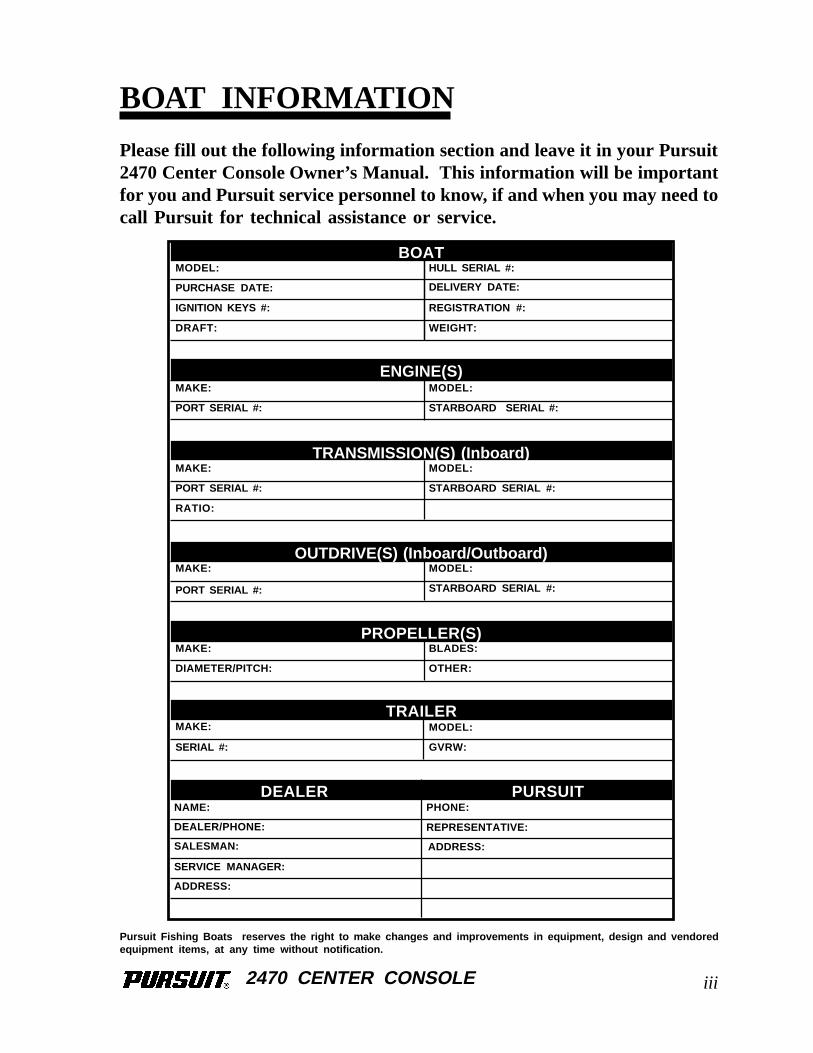
Pursuit Fishing Boats reserves the right to make changes and improvements in equipment, design and vendoredequipment items, at any time without notification.
Please fill out the following information section and leave it in your Pursuit2470 Center Console Owner’s Manual. This information will be importantfor you and Pursuit service personnel to know, if and when you may need tocall Pursuit for technical assistance or service.

2470 CENTER CONSOLE
THIS PAGE WAS LEFT BLANKINTENTIONALLY
2470 CENTER CONSOLE
Warranty and Warranty Registration CardsThe Pursuit Limited Warranty Statement is included with your boat. It has been written to be clearlystated and easily understood. If you have any questions after reading the warranty, please contactthe Pursuit Customer Relations Department.
Pursuit, engine manufacturers, and the suppliers of major components maintain their ownmanufacturer's warranty and service facilities. It is important that you properly complete thewarranty registration cards included with your boat and engine(s) and mail them back to themanufacturer to register your ownership. This should be done within 15 days of the date ofpurchase and before the boat is put into service. A form for recording this information is providedat the beginning of this manual. This information will be important for you and service personnelto know, if and when you may need service or technical information.
The boat warranty registration requires the Hull Identification Number “HIN” which is locatedon the starboard side of the transom, just below the rubrail. The engine warranty registrationrequires the engine serial number(s). Please refer to the engine owner's manual for the location ofthe serial number(s).
IMPORTANT:All boat manufacturers are required by the Federal Boat Safety Act of 1971 to notify first timeowners in the event any defect is discovered “which creates a substantial risk of personal injury tothe public.” It is essential that we have your warranty registration card complete with yourname and mailing address in our files so that we can comply with the law if it should becomenecessary.
Product ChangesPursuit is committed to the continuous improvement of our boats. As a result, some of theequipment described in this manual or pictured in the catalog may change or no longer be available.Pursuit reserves the right to change standard equipment, optional equipment and specifi-cations without notice or obligation. If you have questions about the equipment on your Pursuit,please contact the Pursuit Customer Relations Department.
Transferring the WarrantyFor a transfer fee, S2 Yachts will extend warranty coverage to subsequent owners of Pursuit modelsfor the duration of the original warranty period. Please refer to the Pursuit Limited WarrantyStatement for the procedure to transfer the warranty.
To take advantage of this program, notification of the change of ownership, including the newowner's name, address and telephone number together with the appropriate fee, must be sent toPursuit Fishing Boats, Customer Relations Department, 3901 St. Lucie Boulevard, Ft. Pierce,Florida 34946, within 30 days of the date of resale.
iv
IMPORTANT INFORMATION
2470 CENTER CONSOLE
S2 Yachts will confirm, in writing, that the transfer of the warranty has taken place. After which,the transferee will be treated as the original purchaser as outlined in the Pursuit Limited WarrantyStatement.
ServiceAll warranty repairs must be performed by an authorized Pursuit dealer. Should a problem developthat is related to faulty workmanship or materials, as stated in the Limited Warranty, you shouldcontact your Pursuit dealer to arrange for the necessary repair. If you are not near your dealer oranother authorized Pursuit dealer or the dealer fails to remedy the cause of the problem, then contactthe Pursuit Customer Relations Department within 15 days. It is the boat owner's responsibilityto deliver the boat to the dealer for warranty service.
IMPORTANT INFORMATION
v
2470 CENTER CONSOLE
OWNER'S/OPERATOR'SRESPONSIBILITIES
Registration and NumberingFederal law requires that all undocumented vessels equipped with propulsion machinery beregistered in the state of principal use. A certificate of number will be issued upon registering theboat. These numbers must be displayed on your boat. The owner/operator of a boat must carrya valid certificate of number whenever the boat is in use. When moved to a new state of principaluse, the certificate is valid for 60 days.
In order to be valid, the numbers must be installed to the proper specifications. Check with yourdealer or State Boating Authority for numbering requirements. The Coast Guard issues thecertificate of number in Alaska; all others are issued by the state.
InsuranceIn most states the boat owner is legally responsible for damages or injuries he or someone elseoperating the boat causes. Responsible boaters carry adequate liability and property damageinsurance for their boat. You should also protect the boat against physical damage and theft. Somestates have laws requiring minimum insurance coverage. Contact your dealer or State BoatingAuthority for information on the insurance requirements in your boating area.
Reporting Boating AccidentsAll boating accidents must be reported by the operator or owner of the boat to the proper marinelaw enforcement authority for the state in which the accident occurred. Immediate notification isrequired if a person dies or disappears as a result of a recreational boating accident.
If a person dies or there are injuries requiring more than first aid, a formal report must be filed within48 hours.
A formal report must be made within 10 days for accidents involving more than $500.00 damageor the complete loss of a boat.
A Boating Accident Report form is located near the back of this manual to assist you in reportingan accident. If you need additional information regarding accident reporting, please call theBoating Safety Hotline, 800-368-5647.
EducationIf you are not an experienced boater, we recommend that the boat operator and other people thatnormally accompany the operator, enroll in a boating safety course. Organizations such as the U.S.Power Squadrons, United States Coast Guard Auxiliary, State Boating Authorities and theAmerican Red Cross offer excellent boating educational programs. These courses are worthwhileeven for experienced boaters to sharpen your skills or bring you up to date on current rules and
vi
2470 CENTER CONSOLE
regulations. They can also help in providing local navigational information when moving to a newboating area. Contact your dealer, State Boating Authority or the Boating Safety Hotline, 800-368-5647 for further information on boating safety courses.
Required EquipmentU.S. Coast Guard regulations require certain equipment on each boat. The Coast Guard also setsminimum safety standards for vessels and associated equipment. To meet these standards some ofthe equipment must be Coast Guard approved. “Coast Guard Approved Equipment” has beendetermined to be in compliance with USCG specifications and regulations relating to performance,construction, or materials. The equipment requirements vary according to the length, type of boat,and the propulsion system. Some of the Coast Guard equipment is described in the SafetyEquipment chapter of this manual. For a more detailed description, obtain “Federal RequirementsAnd Safety Tips For Recreational Boats” by contacting the Boating Safety Hotline 800-368-5647or your local marine dealer or retailer and read the book “Sportfish, Cruisers and Yachts” includedwith your boat.
Some state and local agencies impose similar equipment requirements on waters that do not fallunder Coast Guard jurisdiction. These agencies may also require additional equipment that is notrequired by the Coast Guard. Your dealer or local boating authority can provide you with additionalinformation for the equipment requirements for your boating area.
OWNER'S/OPERATOR'SRESPONSIBILITIES
vii
2470 CENTER CONSOLE
TABLE OF CONTENTS
Chapter 1:Chapter 1:Chapter 1:Chapter 1:Chapter 1: Propulsion System
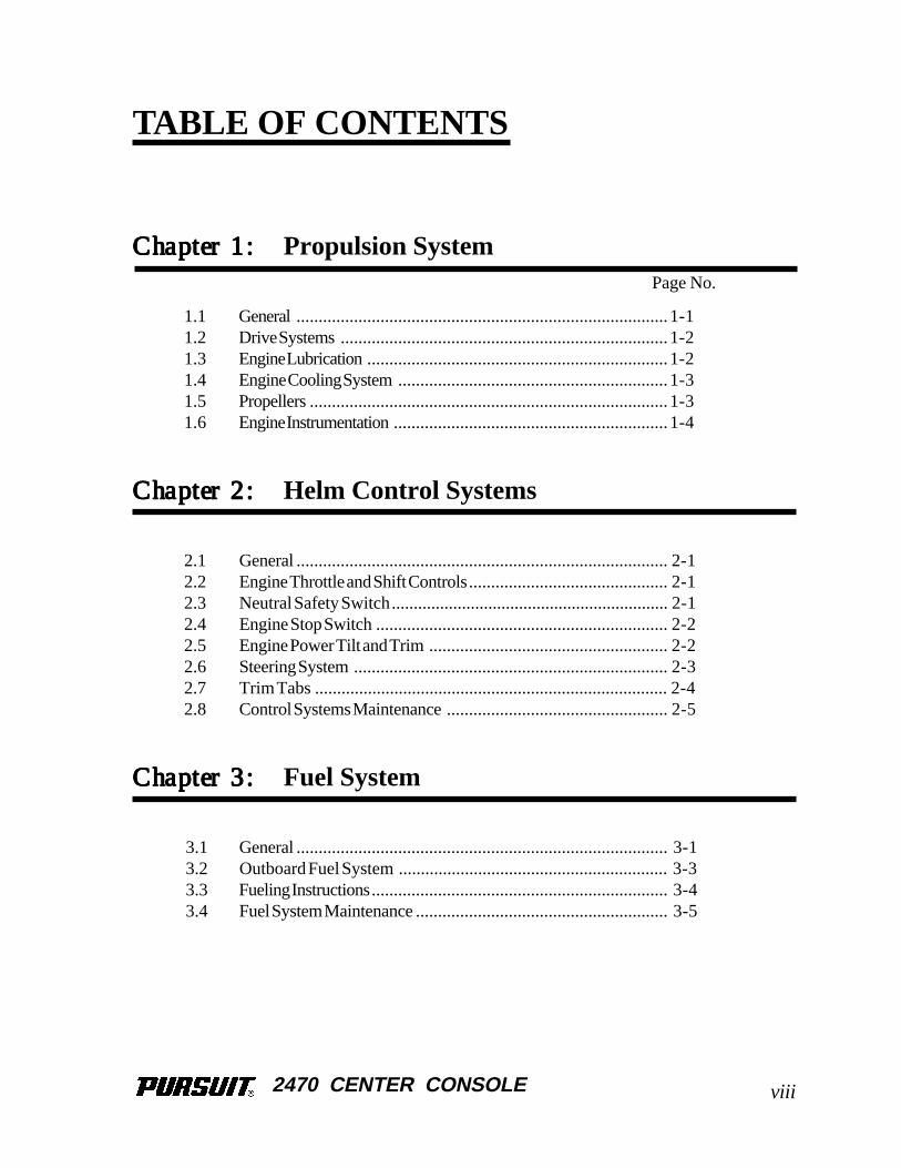
1.1 General....................................................................................1-11.2 Drive Systems..........................................................................1-21.3 Engine Lubrication....................................................................1-21.4 Engine Cooling System.............................................................1-31.5 Propellers.................................................................................1-31.6 Engine Instrumentation..............................................................1-4
Chapter 2:Chapter 2:Chapter 2:Chapter 2:Chapter 2: Helm Control Systems
2.1 General.................................................................................... 2-12.2 Engine Throttle and Shift Controls............................................. 2-12.3 Neutral Safety Switch............................................................... 2-12.4 Engine Stop Switch.................................................................. 2-22.5 Engine Power Tilt and Trim...................................................... 2-22.6 Steering System....................................................................... 2-32.7 Trim Tabs ................................................................................ 2-42.8 Control Systems Maintenance.................................................. 2-5
Chapter 3:Chapter 3:Chapter 3:Chapter 3:Chapter 3: Fuel System
3.1 General.................................................................................... 3-13.2 Outboard Fuel System ............................................................. 3-33.3 Fueling Instructions................................................................... 3-43.4 Fuel System Maintenance......................................................... 3-5
Page No.
viii
2470 CENTER CONSOLE
TABLE OF CONTENTS
Chapter 4:Chapter 4:Chapter 4:Chapter 4:Chapter 4: Electrical System
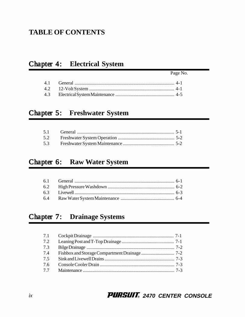
4.1 General................................................................................... 4-14.2 12-Volt System ....................................................................... 4-14.3 Electrical System Maintenance................................................. 4-5
Chapter 5:Chapter 5:Chapter 5:Chapter 5:Chapter 5: Freshwater System
5.1 General ................................................................................. 5-15.2 Freshwater System Operation ............................................... 5-25.3 Freshwater System Maintenance ........................................... 5-2
Chapter 6:Chapter 6:Chapter 6:Chapter 6:Chapter 6: Raw Water System
6.1 General................................................................................... 6-16.2 High Pressure Washdown ........................................................ 6-26.3 Livewell................................................................................... 6-36.4 Raw Water System Maintenance ............................................. 6-4
Chapter 7:Chapter 7:Chapter 7:Chapter 7:Chapter 7: Drainage Systems
7.1 Cockpit Drainage .................................................................... 7-17.2 Leaning Post and T-Top Drainage ............................................ 7-17.3 Bilge Drainage......................................................................... 7-27.4 Fishbox and Storage Compartment Drainage ............................ 7-27.5 Sink and Livewell Drains.......................................................... 7-37.6 Console Cooler Drain .............................................................. 7-37.7 Maintenance............................................................................ 7-3
Page No.
ix
2470 CENTER CONSOLE
TABLE OF CONTENTS
Chapter 8:Chapter 8:Chapter 8:Chapter 8:Chapter 8: Safety Equipment
8.1 General.................................................................................... 8-18.2 Engine Alarms.......................................................................... 8-18.3 Neutral Safety Switch............................................................... 8-28.4 Engine Stop Switch.................................................................. 8-28.5 Required Safety Equipment....................................................... 8-28.6 Maximum Capacity Rating........................................................ 8-58.7 Additional Safety Equipment..................................................... 8-5
Chapter 9:Chapter 9:Chapter 9:Chapter 9:Chapter 9: Operation
9.1 General.................................................................................... 9-19.2 Rules of the Road ..................................................................... 9-19.3 Pre-Cruise System Check ........................................................ 9-39.4 Operating Your Boat................................................................ 9-59.5 Grounding and Towing............................................................. 9-79.6 Water Skiing............................................................................ 9-89.7 Fishing.................................................................................... 9-99.8 Trailering Your Boat................................................................ 9-9
Chapter 10:Chapter 10:Chapter 10:Chapter 10:Chapter 10: Exterior Equipment
10.1 Deck........................................................................................10-110.2 Hull ..........................................................................................10-310.3 Cockpit Equipment...................................................................10-310.4 Center Console ........................................................................ 10-4
Page No.
x
2470 CENTER CONSOLE
Page No.
TABLE OF CONTENTS
Chapter 11:Chapter 11:Chapter 11:Chapter 11:Chapter 11: Interior Equipment
11.1 Portable Head ..........................................................................11-111.2 Marine Head System................................................................11-2
Chapter 12:Chapter 12:Chapter 12:Chapter 12:Chapter 12: Routine Maintenance
12.1 Exterior Hull and Deck..............................................................12-112.2 Upholstery, Canvas and Enclosures...........................................12-412.3 Bilge .........................................................................................12-6
Chapter 13:Chapter 13:Chapter 13:Chapter 13:Chapter 13: Seasonal Maintenance
13.1 Lay-up and Storage ..................................................................13-113.2 Winterizing................................................................................13-413.3 Recommissioning.......................................................................13-6
Chapter 14:Chapter 14:Chapter 14:Chapter 14:Chapter 14: Schematics
Twin Engine 12-Volt Wiring Schematic.................................................14-1Single Engine 12-Volt Wiring Schematic................................................14-2Hydraulic Steering System....................................................................14-3Twin Engine Fuel System .....................................................................14-4Single Engine Fuel System.....................................................................14-5Freshwater System...............................................................................14-6Raw Water System - Macerator ...........................................................14-7Raw Water System - Without Macerator ..............................................14-8Drainage System...................................................................................14-9
xi
2470 CENTER CONSOLE
Appendix A: Glossary of Terms ............................................................ A-1
Appendix B: Maintenance Log .............................................................. B-1
Appendix C: Boating Accident Report ................................................... C-1
TABLE OF CONTENTS
xii

2470 CENTER CONSOLE
THIS PAGE WAS LEFT BLANKINTENTIONALLY
2470 CENTER CONSOLE
Chapter 1:Chapter 1:Chapter 1:Chapter 1:Chapter 1:
PROPULSION SYSTEM
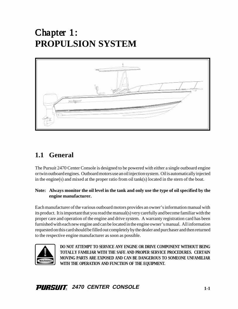
1.1 General
The Pursuit 2470 Center Console is designed to be powered with either a single outboard engineor twin outboard engines. Outboard motors use an oil injection system. Oil is automatically injectedin the engine(s) and mixed at the proper ratio from oil tank(s) located in the stern of the boat.
Note: Always monitor the oil level in the tank and only use the type of oil specified by theengine manufacturer.
Each manufacturer of the various outboard motors provides an owner’s information manual withits product. It is important that you read the manual(s) very carefully and become familiar with theproper care and operation of the engine and drive system. A warranty registration card has beenfurnished with each new engine and can be located in the engine owner’s manual. All informationrequested on this card should be filled out completely by the dealer and purchaser and then returnedto the respective engine manufacturer as soon as possible.
DO NOT ATTEMPT TO SERVICE ANY ENGINE OR DRIVE COMPONENT WITHOUT BEINGTOTALLY FAMILIAR WITH THE SAFE AND PROPER SERVICE PROCEDURES. CERTAINMOVING PARTS ARE EXPOSED AND CAN BE DANGEROUS TO SOMEONE UNFAMILIARWITH THE OPERATION AND FUNCTION OF THE EQUIPMENT.
1-1
2470 CENTER CONSOLE
DO NOT INHALE EXHAUST FUMES! EXHAUST CONTAINS CARBON MONOXIDE THAT ISCOLORLESS AND ODORLESS. CARBON MONOXIDE IS A DANGEROUS GAS THAT IS PO-TENTIALLY LETHAL.
1.2 Drive Systems
Each outboard motor is a complete drive system with the gear case being just forward of thepropeller and connected to the power head with a vertical drive shaft. Other than the routinemaintenance outlined in the engine owner’s manual, there is little to be concerned with unless theboat is to be kept in saltwater for extended periods of time. Then, the main concerns are marinegrowth and galvanic corrosion.
Marine growth occurs when components are left in the water for extended periods and can causepoor performance or permanent damage to the exposed components. The type of growth and howquickly it occurs is relative to the water conditions in your boating area. Water temperature,pollution, current, etc. can have an effect on marine growth.
Galvanic corrosion is the corrosion process occurring when different metals are submerged in anelectrolyte. Sea water is an electrolyte and submerged engine components must be properlyprotected. Outboard motors are equipped with sacrificial zinc anodes to prevent galvanic corrosionproblems. The zinc anodes must be monitored and replaced as necessary. For locations andmaintenance, please refer to the engine owner's manual.
When leaving the boat in the water, tilt the motor as high as possible. This will decrease the riskof marine growth around the cooling inlets, propeller and exhaust ports and damage from galvaniccorrosion.
DO NOT PAINT THE OUTBOARD MOTORS WITH ANTIFOULING PAINTS DESIGNED FORBOAT HULLS. MANY OF THESE PAINTS CAN CAUSE SEVERE DAMAGE TO THE EN-GINES. CONTACT YOUR PURSUIT DEALER OR ENGINE MANUFACTURER FOR INFOR-MATION ON THE PROPER PAINTING PROCEDURES.
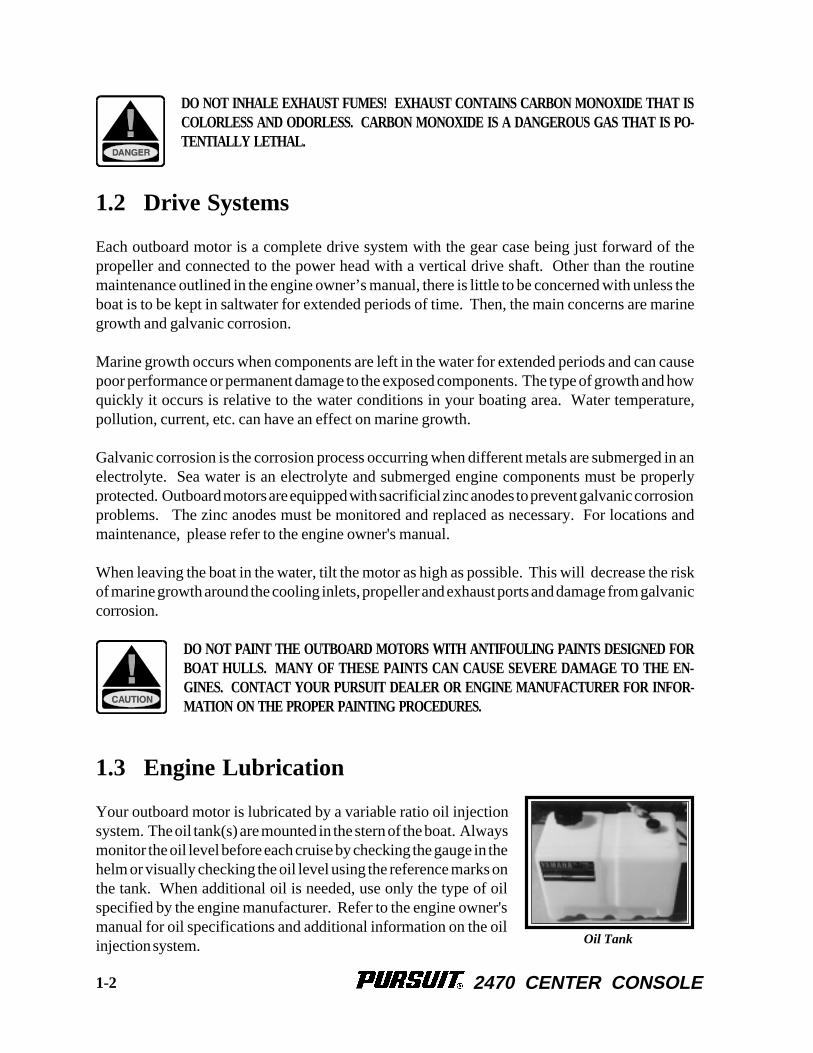
1.3 Engine Lubrication
Your outboard motor is lubricated by a variable ratio oil injectionsystem. The oil tank(s) are mounted in the stern of the boat. Alwaysmonitor the oil level before each cruise by checking the gauge in thehelm or visually checking the oil level using the reference marks onthe tank. When additional oil is needed, use only the type of oilspecified by the engine manufacturer. Refer to the engine owner'smanual for oil specifications and additional information on the oilinjection system. Oil Tank
1-2
2470 CENTER CONSOLE
1.4 Engine Cooling System
Outboard engines are raw water (sea water) cooled. Water is pumped through the water inlets,circulated through the engine block, and relinquished with the exhaust gases through the propellerhub. The water pump uses a small impeller made of synthetic rubber. The impeller and water pumpcannot run dry for more than a few seconds. In most outboard motors, some cooling water isdiverted through small ports below the engine cowling. This allows the operator to visually checkthe operation of the cooling system. When the engine is started, always check for a steady streamof water coming out of those ports.
NEVER RUN AN OUTBOARD MOTOR WITHOUT WATER FLOWING TO THE WATERPUMP. SERIOUS DAMAGE TO THE WATER PUMP IMPELLER OR ENGINE COULD RE-SULT.
Note: If the boat is used in salt or badly polluted water, the engine(s) should be flushed aftereach use. Refer to the engine owner’s manual for the proper engine flushing pro-cedure.
1.5 Propellers
The propellers convert the engine’s power into thrust. They come in a variety of styles, diametersand pitches. The one that will best suit the needs of your Pursuit will depend somewhat on yourapplication and expected average load. Propeller sizes are identified by two numbers stamped onthe prop in sequence. The 1st number in the sequence ( example 14 x 21) is the diameter of thepropeller and the 2nd number is the pitch. Pitch is the theoretical distance traveled by the propellerin each revolution. Always repair or replace a propeller immediately if it has been damaged. Adamaged and therefore out of balance propeller can cause vibration that can be felt in the boat andcould damage the engine gear assembly. Refer to the engine owner’s manual for information onpropeller removal and installation.
RUNNING AGROUND OR STRIKING AN UNDERWATER OBSTRUCTION CAN RESULT IN SE-RIOUS INJURY AND DAMAGE TO THE MOTOR OR BOAT. IF YOUR BOAT RUNSAGROUND, EVALUATE THE DAMAGE THEN PROCEED AT LOW SPEED TO THE NEAR-EST SERVICE FACILITY AND HAVE AN IMMEDIATE INSPECTION MADE BEFORE FUR-THER USE OF THE CRAFT. A DAMAGED BOAT CAN TAKE ON WATER. KEEP ALLLIFE SAVING DEVICES CLOSE AT HAND WHILE DRIVING TO A DOCK AREA. IF THEBOAT CANNOT BE IMMEDIATELY REMOVED FROM THE WATER, THOROUGHLY IN-SPECT THE BILGE AREA FOR LEAKS SO THAT THE BOAT DOES NOT SINK WHILEMOORED.
1-3
2470 CENTER CONSOLE
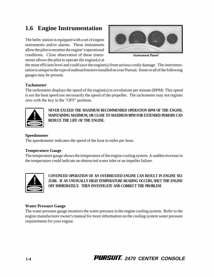
1.6 Engine Instrumentation
The helm station is equipped with a set of engineinstruments and/or alarms. These instrumentsallow the pilot to monitor the engine’s operationalconditions. Close observation of these instru-ments allows the pilot to operate the engine(s) atthe most efficient level and could save the engine(s) from serious costly damage. The instrumen-tation is unique to the type of outboard motors installed on your Pursuit. Some or all of the followinggauges may be present.
TachometerThe tachometer displays the speed of the engine(s) in revolutions per minute (RPM) This speedis not the boat speed nor necessarily the speed of the propeller. The tachometer may not registerzero with the key in the "OFF" position.
NEVER EXCEED THE MAXIMUM RECOMMENDED OPERATION RPM OF THE ENGINE.MAINTAINING MAXIMUM, OR CLOSE TO MAXIMUM RPM FOR EXTENDED PERIODS CANREDUCE THE LIFE OF THE ENGINE.
SpeedometerThe speedometer indicates the speed of the boat in miles per hour.
Temperature GaugeThe temperature gauge shows the temperature of the engine cooling system. A sudden increase inthe temperature could indicate an obstructed water inlet or an impeller failure.
CONTINUED OPERATION OF AN OVERHEATED ENGINE CAN RESULT IN ENGINE SEI-ZURE. IF AN UNUSUALLY HIGH TEMPERATURE READING OCCURS, SHUT THE ENGINEOFF IMMEDIATELY. THEN INVESTIGATE AND CORRECT THE PROBLEM.
Water Pressure GaugeThe water pressure gauge monitors the water pressure in the engine cooling system. Refer to theengine manufacturer owner's manual for more information on the cooling system water pressurerequirements for your engine.
Instrument Panel
1-4
2470 CENTER CONSOLE
DO NOT OPERATE THE ENGINE IF LOW WATER PRESSURE IS INDICATED. THIS COULDBE AN INDICATION OF A COOLING SYSTEM BLOCKAGE OR AN IMPELLER FAILURE.IF LOW WATER PRESSURE IS INDICATED, SHUT THE ENGINE OFF TO INVESTIGATEAND CORRECT THE PROBLEM.
Oil Level GaugeThe oil level gauge indicates the amount of oil in the engine oil tank(s).
Fuel GaugeThe fuel gauge indicates the amount of fuel in the fuel tank.
VoltmeterThe voltmeter displays the voltage for the battery and the charging system. The normal voltage is11 to 12-volts with the engine off, and 13 to 14.5 volts with the engine(s) running.
Hour MeterThe hour meter keeps a record of the operating time for the engine.
Engine AlarmsMost outboards are equipped with an audible alarm system mounted in the helm area that monitorsselected critical engine systems. The alarm will sound if one of these systems begins to fail. Referto the engine owner’s manual for information on the alarms installed with your engines.
IF THE ENGINE ALARM SOUNDS, IMMEDIATELY SHUT OFF THE ENGINE UNTIL THEPROBLEM IS FOUND AND CORRECTED.
Tilt/Trim GaugeThe tilt/trim gauge monitors the position of the engine. The upper range of the gauge indicates thetilt, which is used for trailering and shallow water operation. The lower range indicates the trimposition. This is the range used to adjust the hull angle while operating your boat on plane. Pleaserefer the engine owner’s manual for more information on the operation of the outboard power tiltand trim.
Fuel Management GaugeFuel management systems are optional equipment with some outboard engines. On Yamaha®
engines, the fuel management gauge is a multifunction gauge used to monitor the gallons per hour,miles per gallon, and engine synchronization. If you have a fuel management system installed onyour boat, please refer to the engine or fuel management manual for information on that system.
1-5
2470 CENTER CONSOLE
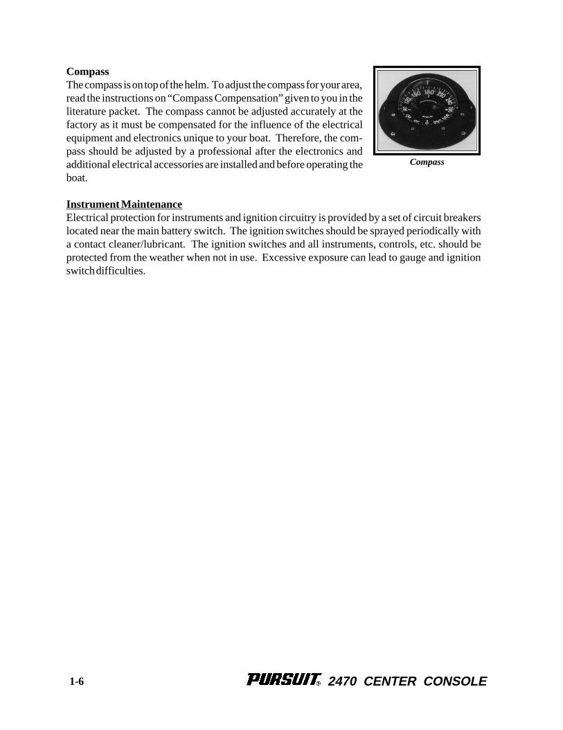
CompassThe compass is on top of the helm. To adjust the compass for your area,read the instructions on “Compass Compensation” given to you in theliterature packet. The compass cannot be adjusted accurately at thefactory as it must be compensated for the influence of the electricalequipment and electronics unique to your boat. Therefore, the com-pass should be adjusted by a professional after the electronics andadditional electrical accessories are installed and before operating theboat.
Instrument MaintenanceElectrical protection for instruments and ignition circuitry is provided by a set of circuit breakerslocated near the main battery switch. The ignition switches should be sprayed periodically witha contact cleaner/lubricant. The ignition switches and all instruments, controls, etc. should beprotected from the weather when not in use. Excessive exposure can lead to gauge and ignitionswitch difficulties.
1-6
Compass
2470 CENTER CONSOLE
Chapter 2:Chapter 2:Chapter 2:Chapter 2:Chapter 2:
HELM CONTROL SYSTEMS
2.1 General
The helm controls consist of three systems: the engine throttle and shift controls, the steeringsystem, and the trim tab control switches. These systems provide the operator with the ability tocontrol the direction and attitude of the boat from the helm station.
Each manufacturer of the control components provides an owner’s manual with its product. It isimportant that you read the manuals and become familiar with the proper care and operation of thecontrol systems.
2.2 Engine Throttle and Shift Controls
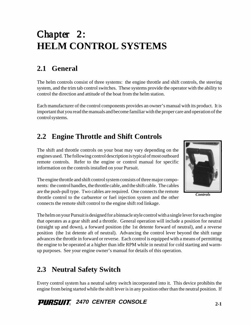
The shift and throttle controls on your boat may vary depending on theengines used. The following control description is typical of most outboardremote controls. Refer to the engine or control manual for specificinformation on the controls installed on your Pursuit.
The engine throttle and shift control system consists of three major compo-nents: the control handles, the throttle cable, and the shift cable. The cablesare the push-pull type. Two cables are required. One connects the remotethrottle control to the carburetor or fuel injection system and the otherconnects the remote shift control to the engine shift rod linkage.
The helm on your Pursuit is designed for a binnacle style control with a single lever for each enginethat operates as a gear shift and a throttle. General operation will include a position for neutral(straight up and down), a forward position (the 1st detente forward of neutral), and a reverseposition (the 1st detente aft of neutral). Advancing the control lever beyond the shift rangeadvances the throttle in forward or reverse. Each control is equipped with a means of permittingthe engine to be operated at a higher than idle RPM while in neutral for cold starting and warm-up purposes. See your engine owner’s manual for details of this operation.
2.3 Neutral Safety Switch
Every control system has a neutral safety switch incorporated into it. This device prohibits theengine from being started while the shift lever is in any position other than the neutral position. If
Controls
2-1
2470 CENTER CONSOLE
the engine will not start, slight movement of the shift lever may be necessary to locate the neutralposition and disengage the safety cutout switch. Control or cable adjustments may be required tocorrect this condition should it persist. See your Pursuit dealer for necessary control and cableadjustments.
The neutral safety switch should be tested periodically to insure that it is operating properly. Totest the neutral safety switch, make sure the engines are tilted down and move the shift levers to theforward position. Make sure the control levers are not advanced past the idle position. Activatethe starter for each engine. The starter should not engage for either engine. Repeat this test withthe shift levers in reverse and the engine throttles at idle. Again, the starter should not engage foreither engine. If the starter for either engine engages with the shift controls in any position otherthan the neutral position, then the neutral safety switch is not functioning properly and you shouldcontact your dealer and have the neutral safety switch repaired before using your boat. If an enginestarts in gear during this test, immediately move the control levers to the neutral position. Turn theengines off and have the problem corrected by a qualified marine mechanic before using the boat.
2.4 Engine Stop Switch
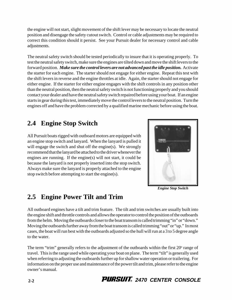
All Pursuit boats rigged with outboard motors are equipped withan engine stop switch and lanyard. When the lanyard is pulled itwill engage the switch and shut off the engine(s). We stronglyrecommend that the lanyard be attached to the driver whenever theengines are running. If the engine(s) will not start, it could bebecause the lanyard is not properly inserted into the stop switch.Always make sure the lanyard is properly attached to the enginestop switch before attempting to start the engine(s).
2.5 Engine Power Tilt and Trim
All outboard engines have a tilt and trim feature. The tilt and trim switches are usually built intothe engine shift and throttle controls and allows the operator to control the position of the outboardsfrom the helm. Moving the outboards closer to the boat transom is called trimming “in” or “down.”Moving the outboards further away from the boat transom is called trimming “out” or “up.” In mostcases, the boat will run best with the outboards adjusted so the hull will run at a 3 to 5 degree angleto the water.
The term “trim” generally refers to the adjustment of the outboards within the first 20o range oftravel. This is the range used while operating your boat on plane. The term “tilt” is generally usedwhen referring to adjusting the outboards further up for shallow water operation or trailering. Forinformation on the proper use and maintenance of the power tilt and trim, please refer to the engineowner’s manual.
Engine Stop Switch
2-2
2470 CENTER CONSOLE
THE ENGINE HOSES AND CABLES OR THE TRANSOM GEL COAT CAN BE DAMAGEDBY TILTING THE ENGINES TO THE FULL UP POSITION WITH THE ENGINES TURNEDTO THE WRONG POSITION. ALL TWIN ENGINE AND MOST SINGLE ENGINE BOATSREQUIRE THE STEERING WHEEL TO BE TURNED COMPLETELY TO STARBOARD BE-FORE TILTING THE ENGINES TO THE FULL UP POSITION. YOU SHOULD MONITORTHE ENGINES AS THEY TILT TO DETERMINE BEST FULL TILT ENGINE POSITION FORYOUR BOAT.
SOME AUTOPILOTS HAVE ENGINE POSITION SENSORS THAT ARE MOUNTED TO THEHYDRAULIC STEERING CYLINDER. WITH THESE AUTOPILOTS, THE ENGINE POSITIONSENSOR BRACKET COULD HIT THE TRANSOM WHEN THE ENGINES ARE TILTED TOTHE FULL UP POSITION AND CAUSE DAMAGE TO THE ENGINE RIGGING, THE AUTO-PILOT OR THE TRANSOM. IF YOU HAVE AN AUTOPILOT INSTALLED ON YOUR BOAT,YOU SHOULD MONITOR THE LOCATION OF THE ENGINE CABLES AND AUTOPILOTBRACKETS AS THE ENGINES ARE TILTED TO DETERMINE THE BEST ENGINE POSI-TION AND MAXIMUM ENGINE TILT FOR YOUR APPLICATION.
2.6 Steering System
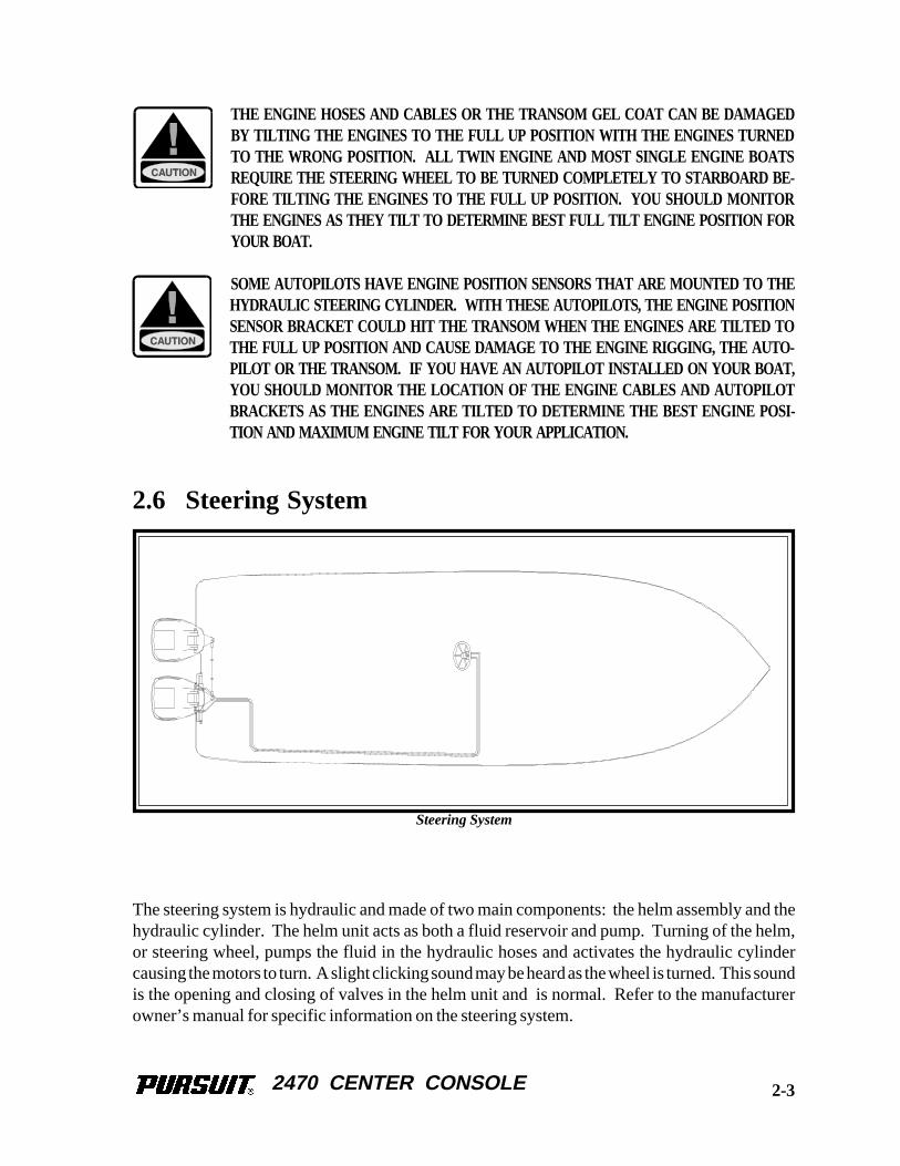
The steering system is hydraulic and made of two main components: the helm assembly and thehydraulic cylinder. The helm unit acts as both a fluid reservoir and pump. Turning of the helm,or steering wheel, pumps the fluid in the hydraulic hoses and activates the hydraulic cylindercausing the motors to turn. A slight clicking sound may be heard as the wheel is turned. This soundis the opening and closing of valves in the helm unit and is normal. Refer to the manufacturerowner’s manual for specific information on the steering system.
2-3
Steering System
2470 CENTER CONSOLE
2.7 Trim Tabs
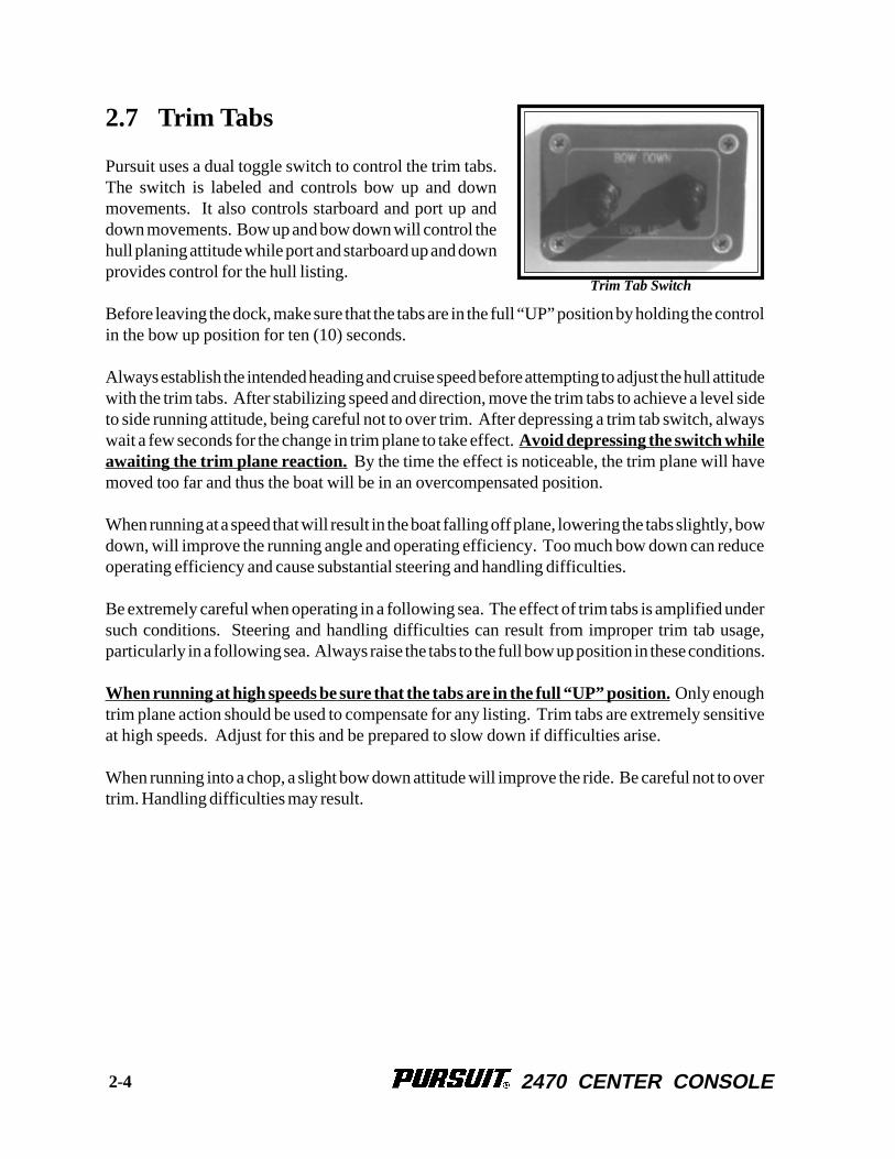
Pursuit uses a dual toggle switch to control the trim tabs.The switch is labeled and controls bow up and downmovements. It also controls starboard and port up anddown movements. Bow up and bow down will control thehull planing attitude while port and starboard up and downprovides control for the hull listing.
Before leaving the dock, make sure that the tabs are in the full “UP” position by holding the controlin the bow up position for ten (10) seconds.
Always establish the intended heading and cruise speed before attempting to adjust the hull attitudewith the trim tabs. After stabilizing speed and direction, move the trim tabs to achieve a level sideto side running attitude, being careful not to over trim. After depressing a trim tab switch, alwayswait a few seconds for the change in trim plane to take effect. Avoid depressing the switch whileawaiting the trim plane reaction. By the time the effect is noticeable, the trim plane will havemoved too far and thus the boat will be in an overcompensated position.
When running at a speed that will result in the boat falling off plane, lowering the tabs slightly, bowdown, will improve the running angle and operating efficiency. Too much bow down can reduceoperating efficiency and cause substantial steering and handling difficulties.
Be extremely careful when operating in a following sea. The effect of trim tabs is amplified undersuch conditions. Steering and handling difficulties can result from improper trim tab usage,particularly in a following sea. Always raise the tabs to the full bow up position in these conditions.
When running at high speeds be sure that the tabs are in the full “UP” position. Only enoughtrim plane action should be used to compensate for any listing. Trim tabs are extremely sensitiveat high speeds. Adjust for this and be prepared to slow down if difficulties arise.
When running into a chop, a slight bow down attitude will improve the ride. Be careful not to overtrim. Handling difficulties may result.
2-4
Trim Tab Switch
2470 CENTER CONSOLE
2.8 Control Systems Maintenance
Control MaintenancePeriodic inspection of the control systems and all connections should be made. Signs of rust,corrosion, wear, or other deterioration should immediately be serviced. Generally, periodiclubrication of all moving parts and connections with a light waterproof grease is in order.
Lubrication should be performed as often as necessary to keep the system operating smoothly.
Control system adjustments may become necessary. If adjustment becomes necessary, see yourPursuit dealer.
DO NOT ATTEMPT CONTROL SYSTEM ADJUSTMENTS UNLESS YOU ARE FAMILIARWITH CONTROL SYSTEM SERVICING PROCEDURES. MISADJUSTMENT CAN CAUSE LOSSOF CONTROL AND SEVERE ENGINE OR LOWER UNIT DAMAGE.
Steering System MaintenanceA periodic inspection of all steering cables, hoses, linkage and helm assemblies should be made.Signs of corrosion, cracking, loosening of fastenings, excessive wear, or deterioration should beimmediately corrected. Generally, periodic lubrication of all moving parts and connections witha light waterproof grease is in order. Failure to do so could lead to steering system failure that wouldresult in loss of control.
When new, or after repairs, hydraulic steering systems may need to have all air purged from thesystem. Review the information provided by the steering manufacturer for proper specificationsand details on system service and maintenance.
Trim Tab MaintenanceMarine growth can interfere with the proper operation of the trim tab planes and actuators. Toreduce problems due to marine growth, always return the trim tabs to the full “UP” position afteroperating the boat and periodically inspect and clean marine growth from the actuators and planes.
The trim tab fluid should be checked often. Keep the fluid level between the marks on the trim tabpump reservoir.
If your Pursuit will be left in saltwater for extended periods, it may be necessary to install zincanodes on the trim tab planes to prevent galvanic corrosion. Refer to the trim tab owner’s manualfor additional maintenance information and fluid specifications.
2-5

2470 CENTER CONSOLE
THIS PAGE WAS LEFT BLANKINTENTIONALLY
2470 CENTER CONSOLE
Chapter 3:Chapter 3:Chapter 3:Chapter 3:Chapter 3:
FUEL SYSTEM
3.1 General
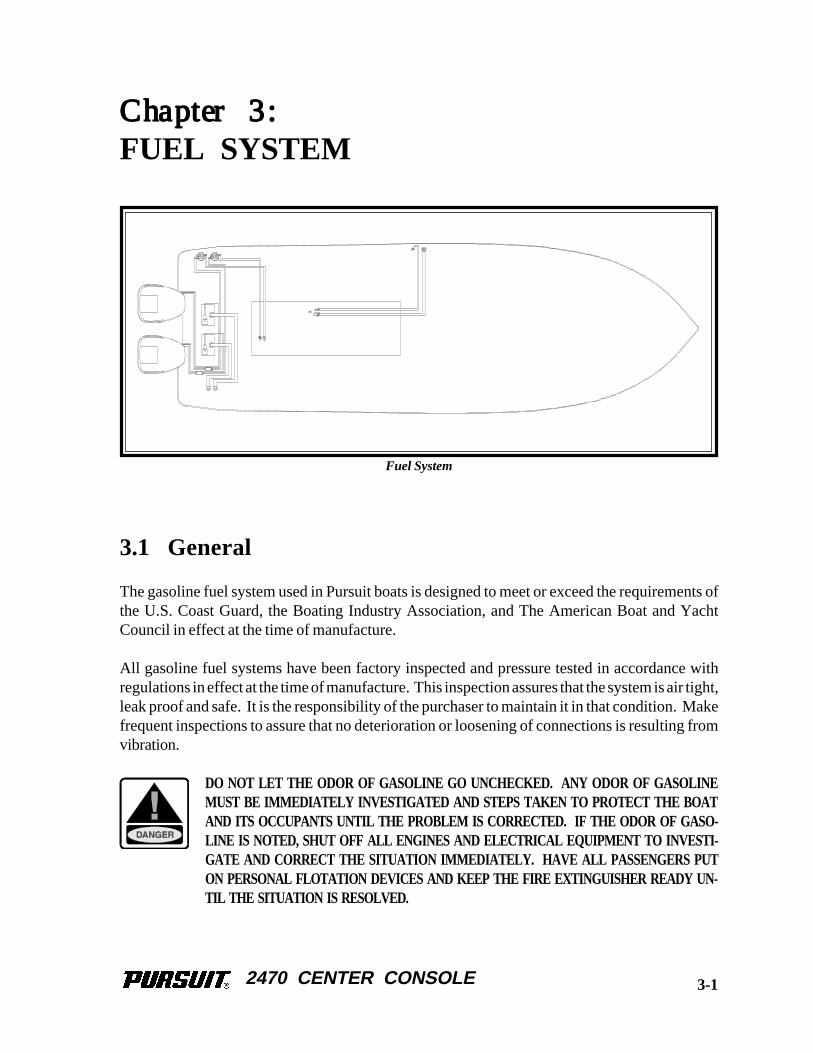
The gasoline fuel system used in Pursuit boats is designed to meet or exceed the requirements ofthe U.S. Coast Guard, the Boating Industry Association, and The American Boat and YachtCouncil in effect at the time of manufacture.
All gasoline fuel systems have been factory inspected and pressure tested in accordance withregulations in effect at the time of manufacture. This inspection assures that the system is air tight,leak proof and safe. It is the responsibility of the purchaser to maintain it in that condition. Makefrequent inspections to assure that no deterioration or loosening of connections is resulting fromvibration.
DO NOT LET THE ODOR OF GASOLINE GO UNCHECKED. ANY ODOR OF GASOLINEMUST BE IMMEDIATELY INVESTIGATED AND STEPS TAKEN TO PROTECT THE BOATAND ITS OCCUPANTS UNTIL THE PROBLEM IS CORRECTED. IF THE ODOR OF GASO-LINE IS NOTED, SHUT OFF ALL ENGINES AND ELECTRICAL EQUIPMENT TO INVESTI-GATE AND CORRECT THE SITUATION IMMEDIATELY. HAVE ALL PASSENGERS PUTON PERSONAL FLOTATION DEVICES AND KEEP THE FIRE EXTINGUISHER READY UN-TIL THE SITUATION IS RESOLVED.
3-1
Fuel System
2470 CENTER CONSOLE
Fuel Withdrawal TubesThe fuel withdrawal tubes are positioned in the fuel tank toachieve optimum fuel usage, fuel line routing, etc. At certainspeeds and hull trim angles, the fuel supply at the withdrawal tanklocation can increase or decrease accordingly. Be extremelycareful when attempting to operate the boat when low on fuel.Though some fuel may be in the tank, the relative trim angle ofthe boat may cause the fuel to flow away from the withdrawal.
Fuel GaugeThis indicates the amount of fuel in the tank. Due to the mechanical nature of the fuel sender,variations in readings during various speeds of operation may occur. This system is merely arelative indication of the available fuel supply and not a calibrated instrument.
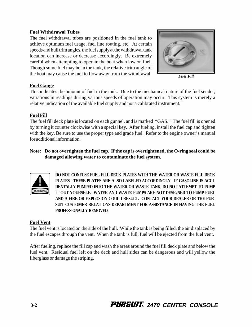
Fuel FillThe fuel fill deck plate is located on each gunnel, and is marked “GAS.” The fuel fill is openedby turning it counter clockwise with a special key. After fueling, install the fuel cap and tightenwith the key. Be sure to use the proper type and grade fuel. Refer to the engine owner’s manualfor additional information.
Note: Do not overtighten the fuel cap. If the cap is overtightened, the O-ring seal could bedamaged allowing water to contaminate the fuel system.
DO NOT CONFUSE FUEL FILL DECK PLATES WITH THE WATER OR WASTE FILL DECKPLATES. THESE PLATES ARE ALSO LABELED ACCORDINGLY. IF GASOLINE IS ACCI-DENTALLY PUMPED INTO THE WATER OR WASTE TANK, DO NOT ATTEMPT TO PUMPIT OUT YOURSELF. WATER AND WASTE PUMPS ARE NOT DESIGNED TO PUMP FUELAND A FIRE OR EXPLOSION COULD RESULT. CONTACT YOUR DEALER OR THE PUR-SUIT CUSTOMER RELATIONS DEPARTMENT FOR ASSISTANCE IN HAVING THE FUELPROFESSIONALLY REMOVED.
Fuel VentThe fuel vent is located on the side of the hull. While the tank is being filled, the air displaced bythe fuel escapes through the vent. When the tank is full, fuel will be ejected from the fuel vent.
After fueling, replace the fill cap and wash the areas around the fuel fill deck plate and below thefuel vent. Residual fuel left on the deck and hull sides can be dangerous and will yellow thefiberglass or damage the striping.
Fuel Fill
3-2
2470 CENTER CONSOLE
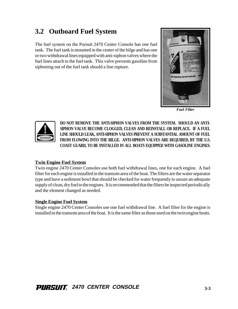
3.2 Outboard Fuel System
The fuel system on the Pursuit 2470 Center Console has one fueltank. The fuel tank is mounted in the center of the bilge and has oneor two withdrawal lines equipped with anti-siphon valves where thefuel lines attach to the fuel tank. This valve prevents gasoline fromsiphoning out of the fuel tank should a line rupture.
DO NOT REMOVE THE ANTI-SIPHON VALVES FROM THE SYSTEM. SHOULD AN ANTI-SIPHON VALVE BECOME CLOGGED, CLEAN AND REINSTALL OR REPLACE. IF A FUELLINE SHOULD LEAK, ANTI-SIPHON VALVES PREVENT A SUBSTANTIAL AMOUNT OF FUELFROM FLOWING INTO THE BILGE. ANTI-SIPHON VALVES ARE REQUIRED, BY THE U.S.COAST GUARD, TO BE INSTALLED IN ALL BOATS EQUIPPED WITH GASOLINE ENGINES.
Twin Engine Fuel SystemTwin engine 2470 Center Consoles use both fuel withdrawal lines, one for each engine. A fuelfilter for each engine is installed in the transom area of the boat. The filters are the water separatortype and have a sediment bowl that should be checked for water frequently to assure an adequatesupply of clean, dry fuel to the engines. It is recommended that the filters be inspected periodicallyand the element changed as needed.
Single Engine Fuel SystemSingle engine 2470 Center Consoles use one fuel withdrawal line. A fuel filter for the engine isinstalled in the transom area of the boat. It is the same filter as those used on the twin engine boats.
3-3
Fuel Filter
2470 CENTER CONSOLE
3.3 Fueling Instructions
FUEL IS VERY FLAMMABLE. BE CAREFUL WHEN FILLING THE FUEL TANK. NO SMOK-ING. NEVER FILL THE TANK WHILE THE ENGINE IS RUNNING. FILL THE FUEL TANKIN AN OPEN AREA. DO NOT FILL THE TANK NEAR OPEN FLAMES.
TO PREVENT DAMAGE TO THE FUEL SYSTEM, USE ONLY A GOOD GRADE OF GASO-LINE FOR GASOLINE ENGINES. DO NOT USE A FUEL THAT CONTAINS HARSH ADDI-TIVES OR IS AN ALCOHOL BLEND. ANY DAMAGE DONE TO THE FUEL SYSTEM THATIS THE RESULT OF USE OF AN ALCOHOL BLEND, IS NOT COVERED BY THE PURSUITWARRANTY. REFER TO THE ENGINE MANUFACTURER OWNER’S MANUAL REGARD-ING FUEL REQUIREMENTS FOR YOUR ENGINE(S).
To fill the fuel tank at a marina, follow this procedure:
1. Make sure all switches are in the “OFF” position.
2. Make sure the boat is securely moored.
3. Make sure all passengers leave the boat.
4. Estimate how much fuel is needed.
Note: When the fuel tank is full, fuel will come out through the fuel vent. The fuel vent islocated on the port side of the boat.
5. A special key to open the fuel cap is supplied.
6. Turn the key counterclockwise to open the cap.
7. Remove the cap.
8. Put the nozzle in the fuel opening.
STATIC ELECTRICITY CAN BE GENERATED WHILE FUELING AND CAN CAUSE A FIREOR EXPLOSION. TO PREVENT STATIC SPARKS WHEN FILLING THE TANK, MAKE SURETHE NOZZLE IS IN CONTACT WITH THE FUEL OPENING.
3-4
2470 CENTER CONSOLE
SPILLED FUEL CAN CAUSE A FIRE OR AN EXPLOSION. MAKE SURE YOU DO NOT SPILLANY FUEL. IF A SMALL AMOUNT OF FUEL IS SPILLED ON THE FIBERGLASS, USE ACLOTH TO REMOVE THE FUEL AND PROPERLY DISPOSE OF THE CONTAMINATEDCLOTH. IF FUEL IS SPILLED ON THE WATER, EXERCISE EXTREME CAUTION. FUELFLOATS ON THE SURFACE OF THE WATER AND CAN IGNITE. IF FUEL IS SPILLEDINTO THE WATER, IMMEDIATELY EVACUATE THE AREA AND NOTIFY THE MARINAAND THE PROPER OFFICIALS.
9. Fill the tank slightly less than the rated capacity to avoid spilling fuel out of thevent and fuel fill and to allow for expansion.
10. Remove the nozzle.
11. Install the fuel cap.
12. Check the fuel compartment and below the deck for fuel odors. If you smell fuel,do not start the engine.
TO REDUCE THE RISK OF A FIRE AND/OR EXPLOSION, DO NOT START THE ENGINE(S)WHEN FUEL FUMES ARE PRESENT. FUEL FUMES ARE DANGEROUS AND HARMFUL TOYOUR HEALTH.
MAKE SURE ALL GASOLINE ODORS ARE INVESTIGATED IMMEDIATELY.
3.4 Fuel System Maintenance
Periodically inspect all connections, clamps and hoses for leakage and damage or deterioration.Replace as necessary. Spray the valves, fuel gauges and ground connections with a metal protector.
Frequently inspect and lubricate the fuel fill cap O-ring seal with petroleum jelly or silicon grease.The O-ring seal prevents water from entering the fuel system through the fuel fill cap and it shouldbe immediately replaced if there is any sign of damage or deterioration.
Periodically, remove the covers from the fuel vents and clean the vent of any debris. Be sure thecovers are replaced securely after cleaning. The covers help prevent water and other foreign matterfrom contaminating the fuel and fuel system. If a vent cover is damaged or lost it should be replacedas soon as possible.
3-5
2470 CENTER CONSOLE
Contaminated fuel may cause serious damage to your engines. The fuel filters must be checkedfor water and other contamination frequently. The filter elements must be changed at least oncea season or more frequently depending on the type of engine and the quality of the fuel. The fuelfilters are located in the stern bilge and are accessed by opening the stern bench seat and removingthe fishbox. The primer bulbs can be accessed through a small hatch in the cockpit near the sternbench seat.
The age of gasoline can effect engine performance. Chemical changes occur as the gasoline agesthat can cause deposits and varnish in the fuel system as well as reduce the octane rating of the fuel.Severely degraded fuel can damage the engine and boat fuel tank and lines. Therefore, if your boatis not being run enough to require at least one full tank of fresh fuel a month, a fuel stabilizer shouldbe added to the gasoline to protect the fuel from degradation. Your dealer or the enginemanufacturer can provide additional information on fuel degradation and fuel stabilizers recom-mended for your engine.
Avoid using fuels with alcohol additives. Gasoline that is an alcohol blend will absorb moisturefrom the air which can reach such concentrations that "phase separation" can occur whereby thewater and alcohol mixture becomes heavy enough to settle out of the gasoline to the bottom of thetank. Since the fuel pick up tube is very near the bottom of the tank, phase separation can causethe engine to run very poorly or not at all. This condition is more severe with methyl alcohol andwill worsen as the alcohol content increases. Water or a jelly like substance in the fuel filters arean indication of phase separation from the use of alcohol blended fuels.
DO NOT DRAIN ANY FUEL INTO THE BILGE. THIS COULD LEAD TO A FIRE OR EX-PLOSION.
AFTER THE FILTER ELEMENT HAS BEEN CHANGED, PRIME THE FUEL SYSTEM ANDCHECK ALL FITTINGS FOR LEAKS BEFORE AND AFTER STARTING THE ENGINE.
3-6
2470 CENTER CONSOLE
Chapter 4:Chapter 4:Chapter 4:Chapter 4:Chapter 4:
ELECTRICAL SYSTEM
4.1 General
Your Pursuit is equipped with a 12-volt D.C. electrical system that draws current from on-boardbatteries.
The 12-volt batteries in your boat are usually the lead-acid type. They will require maintenancesimilar to those found in automobiles. The batteries are located in the stern bilge. The starboardbattery is located near the battery switches and the port battery is below the removable stern tacklelocker. To access the port battery, remove the top tackle locker drawer and remove the quick releasepin, then slide the locker out of the frame.
There are electrical schematics included in this manual to aid in following an individual circuit ofthe boat.
4.2 12-Volt System
The 12-volt system is a fairly standard system. There are two batteries controlled by one batteryswitch (single engine) or two battery switches (twin engines) . The batteries are charged by theengine(s). All 12-volt power is distributed to the 12-volt accessories through individual circuitbreakers located in the 12-volt switch panels. A main in-line circuit breaker located near the batteryswitch protects the system from an overload. Another circuit breaker near the switch protects thecircuit for the automatic float switch for the bilge pump. Most 12-volt accessories are operateddirectly by switches in the helm and accessory switch panels.
PROPER FUSE OR BREAKER PROTECTION MUST BE PROVIDED FOR ALL 12-VOLTEQUIPMENT ADDED. DO NOT OVERLOAD THE ACCESSORY CIRCUIT BREAKERS OROTHER CIRCUITRY THROUGH ADDITIONAL 12-VOLT EQUIPMENT.
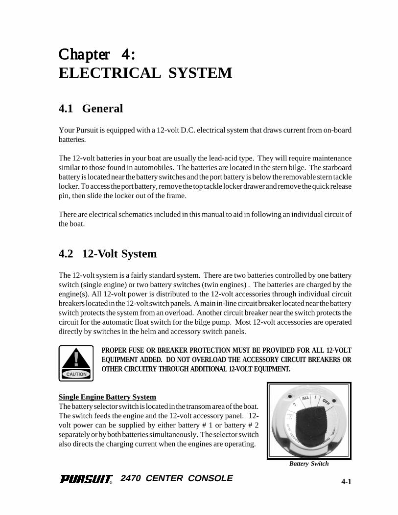
Single Engine Battery SystemThe battery selector switch is located in the transom area of the boat.The switch feeds the engine and the 12-volt accessory panel. 12-volt power can be supplied by either battery # 1 or battery # 2separately or by both batteries simultaneously. The selector switchalso directs the charging current when the engines are operating.
Battery Switch
4-1
2470 CENTER CONSOLE
For example: When the switch is on battery # 1, the engine and the 12-volt system will be suppliedpower by battery # 1. Battery # 2 will be isolated and in reserve. Battery # 1 will be charged bythe alternator. When the selector switch is on battery # 2, the engine and the 12-volt system willbe supplied power by battery # 2. Battery # 1 will be isolated and in reserve. Battery # 2 will thenbe charged by the alternator.
When the selector switch is on “ALL,” the batteries are connected in parallel so the engine and the12-volt system will be supplied power by both batteries. Both batteries will be charged by thealternator. The “ALL” position should only be used when starting the engine, as this requires extraelectrical power, or when both batteries are low and need charging. Otherwise, it is recommendedthat the selector switch be set on battery # 1 or battery # 2 when the engine is operating. While inport, or at anchor, the battery selector switch should be on either the battery # 1 or the battery # 2position. This will keep one battery in reserve for starting the engine. The battery switch shouldbe turned to the “OFF” position when leaving the boat unattended.
Twin Engine Battery SystemThere are two (2) batteries controlled by two (2) battery selector switches located in the transomarea of the boat. The batteries can be charged by either engine separately, or both enginessimultaneously. One battery switch feeds the starboard engine and the 12-volt accessory panel.The other battery switch feeds the port engine. Twelve volt power can be supplied by either battery# 1 or battery # 2 separately or by both batteries simultaneously. The selector switches also directthe charging current when the engines are operating.
For example: When both selector switches are on battery # 1, both engines and the 12-volt panelwill be powered by battery # 1. Battery # 2 will be isolated and in reserve. Battery # 1 will becharged by both alternators. When both selector switches are on battery # 2, both engines and the12-volt panel will be operated by battery # 2. Battery # 1 will now be isolated and in reserve. Battery# 2 will then be charged by both alternators.
When both selector switches are on “ALL,” the batteries are connected in parallel. Thus, bothengines and all 12-volt equipment are powered by both batteries. Battery #1 and battery # 2 willthen be charged by both alternators. The “ALL” position should only be used when starting theengines, as this requires extra electrical power, or in case of a charging system malfunction on oneengine. Otherwise, it is recommended that one selector switch be set on battery # 1 and the otherswitch be on battery # 2 when the engines are operating.
When in port, or at anchor, the switch that supplies the port engine should be “OFF” and the switchthat supplies the starboard engine and the 12-volt accessories should be on either the battery # 1 orthe battery # 2 position. This will keep one battery in reserve for starting the engines. Both batteryswitches should be turned to the “OFF” position when leaving the boat unattended.
4-2
2470 CENTER CONSOLE
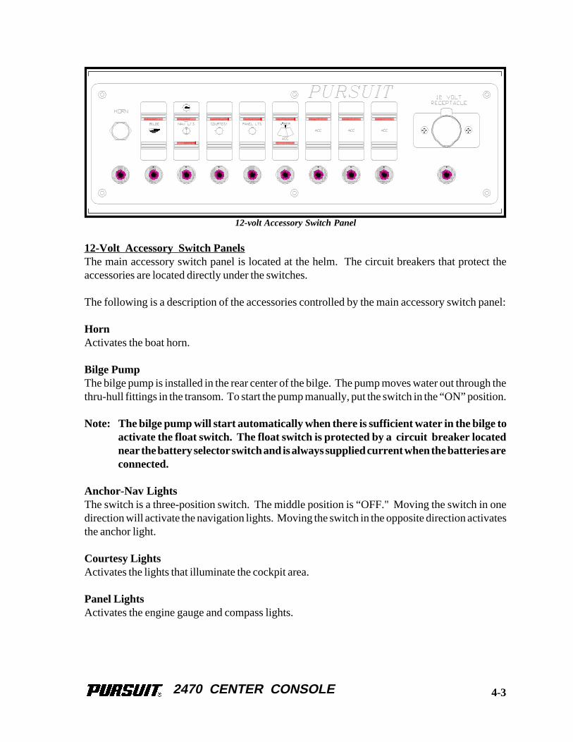
12-Volt Accessory Switch PanelsThe main accessory switch panel is located at the helm. The circuit breakers that protect theaccessories are located directly under the switches.
The following is a description of the accessories controlled by the main accessory switch panel:
HornActivates the boat horn.
Bilge PumpThe bilge pump is installed in the rear center of the bilge. The pump moves water out through thethru-hull fittings in the transom. To start the pump manually, put the switch in the “ON” position.
Note: The bilge pump will start automatically when there is sufficient water in the bilge toactivate the float switch. The float switch is protected by a circuit breaker locatednear the battery selector switch and is always supplied current when the batteries areconnected.
Anchor-Nav LightsThe switch is a three-position switch. The middle position is “OFF." Moving the switch in onedirection will activate the navigation lights. Moving the switch in the opposite direction activatesthe anchor light.
Courtesy LightsActivates the lights that illuminate the cockpit area.
Panel LightsActivates the engine gauge and compass lights.
12-volt Accessory Switch Panel
4-3
2470 CENTER CONSOLE
Windshield WiperActivates the windshield wiper if this option is installed on your boat. If no wiper is installed, thisswitch is reserved for additional accessories.
Accessory Switches (3)These switches are supplied to activate additional equipment that may have been installed byPursuit or your Pursuit dealer. If no accessories are activated by these switches, they remain wiredin the panel in reserve.
12-Volt ReceptacleProvides electrical current for portable 12-volt equipment.
Additional Switch PanelsAdditional switch panels may be located in various locations in the cockpit and helm area of theboat. Most of these panels are equipped with one switch and one circuit breaker. The followingis a description of additional panels that may be on your Pursuit and the accessories they control:
Baitwell SwitchThis switch activates the baitwell circulating pump that supplies water to the baitwell.
Washdown PumpThis switch activates the raw water washdown pump. A pressure switch automatically controlsthe water pump when the system is activated and properly primed.
MaceratorSupplies electrical current to the switch, that controls the macerator overboard discharge pump forthe holding tank. This switch is located near the battery selector switch or the Y-valve in the sternof the boat.
Note: Please refer to Chapter 6 for more information on the baitwell and washdownsystems.
Trim Tab SwitchLocated in the helm. This switch controls the trim tab planes located on the transom of the boat. Itis protected by a breaker located behind the helm at the back of the accessory switch. Please referto Chapter 2 for detailed information on the operation of the trim tab controls.
Windlass SwitchLocated in the helm. This switch controls the optional windlass which is mounted to the deckdirectly above the rope locker. It is protected by a circuit breaker of the type and ratingrecommended by the windlass manufacturer.
4-4
2470 CENTER CONSOLE
Windlass BreakerThe windlass breaker is located on the helm next to the windlass switch. Push the button in toactivate the windlass control switch and push it again to return the breaker to “OFF” whenever thewindlass is not in use. This breaker is provided to reduce the possibility of accidentally activatingthe windlass.
4.3 Electrical System Maintenance
D.C. Electrical System MaintenanceAt least once a year, spray all exposed electrical components behind the helm and in the plugs, witha protector. Exterior light fixture bulbs should be removed and the metal contact areas coated witha non-water soluble lubricant like petroleum jelly. The sockets should be sprayed with a protector.Care must be taken not to get any oil or petroleum jelly on the glass portion of the bulbs as this willcause the bulb to overheat and burn out.
WHEN REPLACING LIGHT BULBS IN MARINE LIGHT FIXTURES, ALWAYS USE A BULBWITH THE SAME RATING AS THE ORIGINAL. USING A DIFFERENT BULB COULD CAUSETHE FIXTURE TO OVERHEAT AND MELT OR SHORT CIRCUIT.
Inspect all wiring for proper support, sound insulation, and tight terminals, paying particularattention to portable appliance cords and plugs.
Check all below deck wiring to be sure it is properly supported, that the insulation is sound, andthat there are no loose or corroded terminals. Corroded terminals should be thoroughly cleanedwith sandpaper, or replaced, tightened securely and sprayed with a metal and electrical protector.Inspect all engine wiring.
Check the electrolyte level in the batteries regularly and add distilled water as necessary. If thebatteries are frequently charged by an automatic battery charger, the electrolyte level will have tobe checked more often. Keep the battery tops clean and dry. Dirt and water can conduct electricityfrom one post to the other causing the battery to discharge. The battery posts should be kept freeof corrosion. Remove the cables and clean the posts and cable clamps with a battery post cleaneror sandpaper as required. Coating the battery posts and cable clamps with petroleum jelly willprotect them and reduce corrosion. Battery cables, both hot and ground, must be replaced whenthey show signs of corrosion or fraying. Deteriorated cables cause a considerable voltage loss whenhigh currents are drawn, as for starting the engine.
NEVER USE AN OPEN FLAME IN THE BATTERY STORAGE AREA. AVOID STRIKINGSPARKS NEAR THE BATTERY. A BATTERY CAN EXPLODE IF A FLAME OR SPARK IG-NITES THE HYDROGEN GAS THE BATTERY EMITS WHILE BEING CHARGED.
4-5
2470 CENTER CONSOLE
CORROSION ALLOWED TO BUILD ON THE ELECTRICAL CONNECTORS CAN CAUSE APOOR CONNECTION RESULTING IN SHORTS, GROUND FAULTS OR POOR GROUND CON-NECTIONS. ELECTRICAL CONNECTORS SHOULD CHECKED AT LEAST ANNUALLY ANDCLEANED AS REQUIRED. DO NOT ALLOW CORROSION TO BUILD ON CONNECTIONS.
THE ELECTRICAL SYSTEM ALWAYS SHOULD BE DISCONNECTED FROM THE POWERSOURCE BEFORE INSPECTING OR SERVICING THE SYSTEM. NEVER SERVICE ANY COM-PONENT OF AN ELECTRICAL SYSTEM WHILE IT IS ENERGIZED.
4-6
2470 CENTER CONSOLE
Chapter 5:Chapter 5:Chapter 5:Chapter 5:Chapter 5:
FRESHWATER SYSTEM
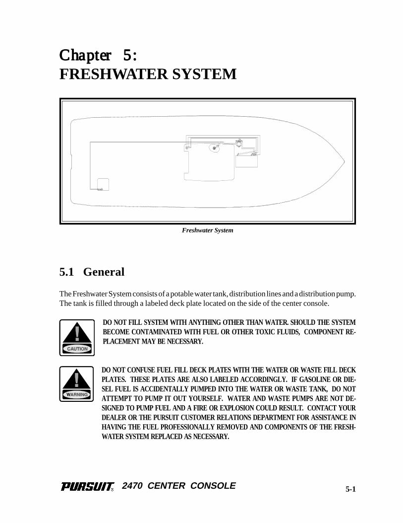
5.1 General
The Freshwater System consists of a potable water tank, distribution lines and a distribution pump.The tank is filled through a labeled deck plate located on the side of the center console.
DO NOT FILL SYSTEM WITH ANYTHING OTHER THAN WATER. SHOULD THE SYSTEMBECOME CONTAMINATED WITH FUEL OR OTHER TOXIC FLUIDS, COMPONENT RE-PLACEMENT MAY BE NECESSARY.
DO NOT CONFUSE FUEL FILL DECK PLATES WITH THE WATER OR WASTE FILL DECKPLATES. THESE PLATES ARE ALSO LABELED ACCORDINGLY. IF GASOLINE OR DIE-SEL FUEL IS ACCIDENTALLY PUMPED INTO THE WATER OR WASTE TANK, DO NOTATTEMPT TO PUMP IT OUT YOURSELF. WATER AND WASTE PUMPS ARE NOT DE-SIGNED TO PUMP FUEL AND A FIRE OR EXPLOSION COULD RESULT. CONTACT YOURDEALER OR THE PURSUIT CUSTOMER RELATIONS DEPARTMENT FOR ASSISTANCE INHAVING THE FUEL PROFESSIONALLY REMOVED AND COMPONENTS OF THE FRESH-WATER SYSTEM REPLACED AS NECESSARY.
Freshwater System
5-1
2470 CENTER CONSOLE
5.2 Freshwater System Operation
Fill the water supply tank slowly through the labeled deck plate.
After filling the water tank, partially open all faucets. The freshwater switch on the 12-volt panelshould be on. Allow the pump to run until all of the air is purged from the system and a steady streamof water is flowing from each outlet. Next, turn off the faucets one by one. As the pressure buildsthe pump will automatically shut off.
When properly primed and activated the water system will operate much like the water system ina home. An automatic pressure sensor keeps the system pressurized. If the system has been recentlyfilled or has not been used for an extended period, air bubbles may accumulate at the pump and thesystem may have to be reprimed. Whenever the boat is left unattended, the freshwater pump switchshould be placed in the “OFF” position.
DO NOT ALLOW THE FRESHWATER PUMP TO RUN DRY. THIS CAN RESULT IN DAM-AGE TO THE PUMP.
5.3 Freshwater System Maintenance
Information supplied with water system components, by the equipment manufacturers, is includedwith this manual. Refer to this information for additional operation and service data.
The following items should be done routinely to maintain your Freshwater System:
Periodically, remove the cover from the water tank vent and clean the vent of any debris. Be surethe covers are replaced securely after cleaning. The covers help prevent water and other foreignmatter from contaminating the water system. If a vent cover is damaged or lost it should be replacedas soon as possible.
Remove the filter screens from the faucet spouts and eliminate any accumulation of debris. A buildup of debris can cause the pump to cycle excessively.
Periodically spray the pumps and metal components with a metal protector.
The batteries must be properly maintained and charged. Operating the pressure pump from abattery with a low charge could lead to pump failure.
Add a commercially available potable water conditioner to the water tank(s) to keep them fresh.
5-2
2470 CENTER CONSOLE
THE BATTERIES MUST BE PROPERLY CHARGED. OPERATING THE FRESHWATER PUMPFROM A BATTERY WITH A LOW CHARGE MAY LEAD TO A PUMP FAILURE.
5-3
2470 CENTER CONSOLE
THIS PAGE WAS LEFT BLANKINTENTIONALLY
2470 CENTER CONSOLE
Chapter 6:Chapter 6:Chapter 6:Chapter 6:Chapter 6:
RAW WATER SYSTEM
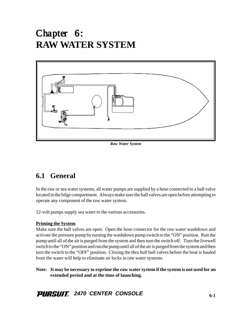
6.1 General
In the raw or sea water systems, all water pumps are supplied by a hose connected to a ball valvelocated in the bilge compartment. Always make sure the ball valves are open before attempting tooperate any component of the raw water system.
12-volt pumps supply sea water to the various accessories.
Priming the SystemMake sure the ball valves are open. Open the hose connector for the raw water washdown andactivate the pressure pump by turning the washdown pump switch to the “ON” position. Run thepump until all of the air is purged from the system and then turn the switch off. Turn the livewellswitch to the “ON” position and run the pump until all of the air is purged from the system and thenturn the switch to the “OFF” position. Closing the thru hull ball valves before the boat is hauledfrom the water will help to eliminate air locks in raw water systems.
Note: It may be necessary to reprime the raw water system if the system is not used for anextended period and at the time of launching.
Raw Water System
6-1
2470 CENTER CONSOLE
6.2 High Pressure Washdown
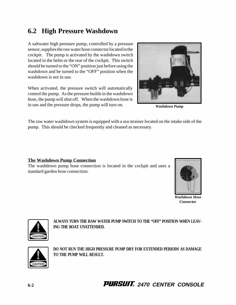
A saltwater high pressure pump, controlled by a pressuresensor, supplies the raw water hose connector located in thecockpit. The pump is activated by the washdown switchlocated in the helm or the rear of the cockpit. This switchshould be turned to the “ON” position just before using thewashdown and be turned to the “OFF” position when thewashdown is not in use.
When activated, the pressure switch will automaticallycontrol the pump. As the pressure builds in the washdownhose, the pump will shut off. When the washdown hose isin use and the pressure drops, the pump will turn on.
The raw water washdown system is equipped with a sea strainer located on the intake side of thepump. This should be checked frequently and cleaned as necessary.
The Washdown Pump ConnectionThe washdown pump hose connection is located in the cockpit and uses astandard garden hose connection.
ALWAYS TURN THE RAW WATER PUMP SWITCH TO THE “OFF” POSITION WHEN LEAV-ING THE BOAT UNATTENDED.
DO NOT RUN THE HIGH PRESSURE PUMP DRY FOR EXTENDED PERIODS AS DAMAGETO THE PUMP WILL RESULT.
Washdown Pump
Washdown HoseConnector
6-2
2470 CENTER CONSOLE
6.3 Livewell
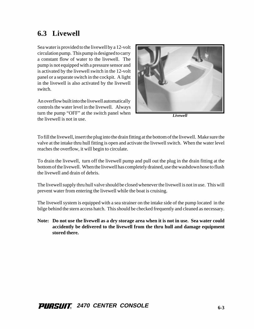
Sea water is provided to the livewell by a 12-voltcirculation pump. This pump is designed to carrya constant flow of water to the livewell. Thepump is not equipped with a pressure sensor andis activated by the livewell switch in the 12-voltpanel or a separate switch in the cockpit. A lightin the livewell is also activated by the livewellswitch.
An overflow built into the livewell automaticallycontrols the water level in the livewell. Alwaysturn the pump “OFF” at the switch panel whenthe livewell is not in use.
To fill the livewell, insert the plug into the drain fitting at the bottom of the livewell. Make sure thevalve at the intake thru hull fitting is open and activate the livewell switch. When the water levelreaches the overflow, it will begin to circulate.
To drain the livewell, turn off the livewell pump and pull out the plug in the drain fitting at thebottom of the livewell. When the livewell has completely drained, use the washdown hose to flushthe livewell and drain of debris.
The livewell supply thru hull valve should be closed whenever the livewell is not in use. This willprevent water from entering the livewell while the boat is cruising.
The livewell system is equipped with a sea strainer on the intake side of the pump located in thebilge behind the stern access hatch. This should be checked frequently and cleaned as necessary.
Note: Do not use the livewell as a dry storage area when it is not in use. Sea water couldaccidently be delivered to the livewell from the thru hull and damage equipmentstored there.
Livewell
6-3
2470 CENTER CONSOLE
6.4 Raw Water System Maintenance
The following items should be done routinely to help maintain your raw water system:
• Check hoses, particularly the sea water supply line, for signs of deterioration.
• Remove and clean the sea water strainers.
• Spray pumps and thru hull valves with a protective oil periodically.
• The fishboxes and livewells should be drained and cleaned after each use.
• Operate all thru hull valves at least once a month to keep them operating properly.
The light assembly for the livewell is accessed from below the cockpit and through an access hatchlocated near the livewell. If the bulb needs replacing, reach through the access hatch and carefullywork the socket out of the light assembly. The wire should be long enough to pull the socket andbulb out of the access hatch. Apply a thin layer of petroleum jelly to the base of the new bulb andinsert it into the socket. Care must be taken not to get any oil or petroleum jelly on the glass portionof the bulb as this will cause the bulb to overheat and burn out. Insert the bulb and socket into thelight assembly.
SHOULD A HOSE RUPTURE, TURN THE PUMP OFF IMMEDIATELY. ALWAYS CLOSETHE THRU HULL VALVE WHEN PERFORMING MAINTENANCE ON A SEA WATER PUMP.
THE BATTERIES MUST BE PROPERLY CHARGED. OPERATING ANY PUMPS FROM ABATTERY WITH A LOW CHARGE MAY LEAD TO A PUMP FAILURE.
THE RAW WATER SYSTEM MUST BE PROPERLY WINTERIZED PRIOR TO WINTER LAY-UP. SEE SECTION ON WINTERIZING.
6-4
2470 CENTER CONSOLE
Chapter 7:Chapter 7:Chapter 7:Chapter 7:Chapter 7:
DRAINAGE SYSTEMS
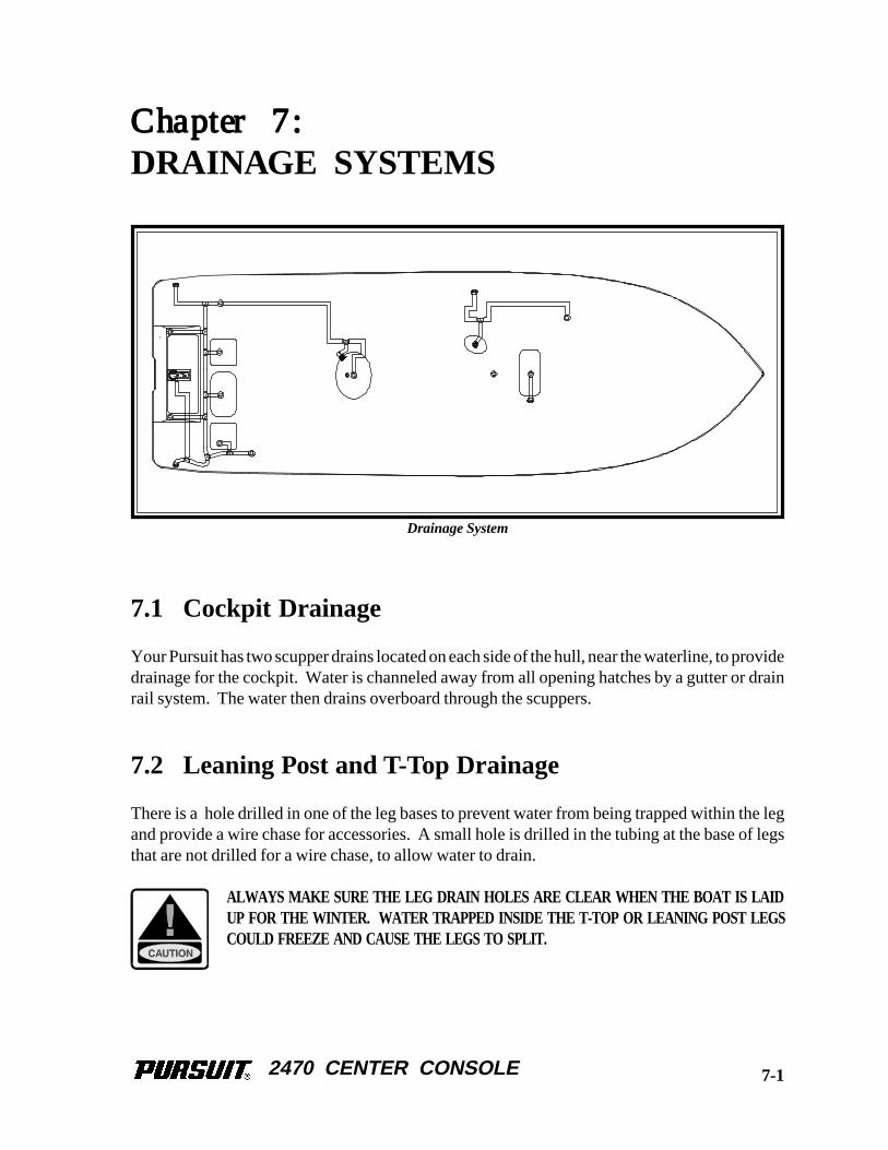
7.1 Cockpit Drainage
Your Pursuit has two scupper drains located on each side of the hull, near the waterline, to providedrainage for the cockpit. Water is channeled away from all opening hatches by a gutter or drainrail system. The water then drains overboard through the scuppers.
7.2 Leaning Post and T-Top Drainage
There is a hole drilled in one of the leg bases to prevent water from being trapped within the legand provide a wire chase for accessories. A small hole is drilled in the tubing at the base of legsthat are not drilled for a wire chase, to allow water to drain.
ALWAYS MAKE SURE THE LEG DRAIN HOLES ARE CLEAR WHEN THE BOAT IS LAIDUP FOR THE WINTER. WATER TRAPPED INSIDE THE T-TOP OR LEANING POST LEGSCOULD FREEZE AND CAUSE THE LEGS TO SPLIT.
Drainage System
7-1
2470 CENTER CONSOLE
7.3 Bilge Drainage
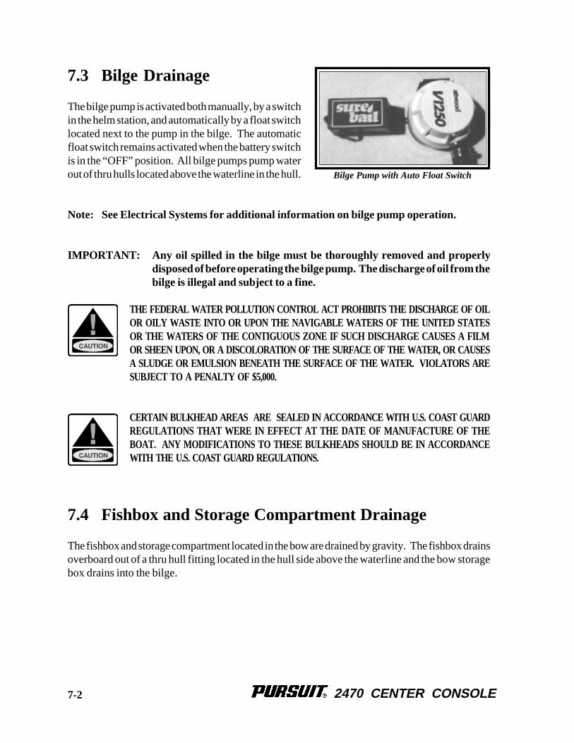
The bilge pump is activated both manually, by a switchin the helm station, and automatically by a float switchlocated next to the pump in the bilge. The automaticfloat switch remains activated when the battery switchis in the “OFF” position. All bilge pumps pump waterout of thru hulls located above the waterline in the hull.
Note: See Electrical Systems for additional information on bilge pump operation.
IMPORTANT: Any oil spilled in the bilge must be thoroughly removed and properlydisposed of before operating the bilge pump. The discharge of oil from thebilge is illegal and subject to a fine.
THE FEDERAL WATER POLLUTION CONTROL ACT PROHIBITS THE DISCHARGE OF OILOR OILY WASTE INTO OR UPON THE NAVIGABLE WATERS OF THE UNITED STATESOR THE WATERS OF THE CONTIGUOUS ZONE IF SUCH DISCHARGE CAUSES A FILMOR SHEEN UPON, OR A DISCOLORATION OF THE SURFACE OF THE WATER, OR CAUSESA SLUDGE OR EMULSION BENEATH THE SURFACE OF THE WATER. VIOLATORS ARESUBJECT TO A PENALTY OF $5,000.
CERTAIN BULKHEAD AREAS ARE SEALED IN ACCORDANCE WITH U.S. COAST GUARDREGULATIONS THAT WERE IN EFFECT AT THE DATE OF MANUFACTURE OF THEBOAT. ANY MODIFICATIONS TO THESE BULKHEADS SHOULD BE IN ACCORDANCEWITH THE U.S. COAST GUARD REGULATIONS.
7.4 Fishbox and Storage Compartment Drainage
The fishbox and storage compartment located in the bow are drained by gravity. The fishbox drainsoverboard out of a thru hull fitting located in the hull side above the waterline and the bow storagebox drains into the bilge.
Bilge Pump with Auto Float Switch
7-2
2470 CENTER CONSOLE
7.5 Sink and Livewell Drains
All sinks and livewells, provided with fresh or raw water, drain by gravity to overboard thru hullslocated in the hull sides just above the waterline. The overflows in the livewells drain into theoverboard drains.
7.6 Console Cooler Drain
The console cooler is drained by gravity. Water is channeled from the cooler to the cockpit soleand then overboard through the scuppers. The cooler should be flushed out and cleaned after eachuse.
7.7 Maintenance
It is essential that the following items be done periodically to maintain proper drainage of your boat:
• Clean the cockpit drain rails with a hose to remove debris that can block water drainage.
• Clean the T-top and leaning post leg drain holes. This is especially important just before winterlay-up.
• Clean the bilge pump strainers of debris and check the bilge for foreign material that can causethe automatic switches to malfunction.
• Frequently test the automatic bilge pump switches for proper operation.
• Flush all gravity drains with fresh water to keep them clean and free flowing.
• Clean and flush the fishboxes and livewells with soap and fresh water or a bilge cleaner aftereach use to keep them clean and fresh.
ALL DRAINS AND PUMPS MUST BE PROPERLY WINTERIZED BEFORE WINTER LAY-UP.
NEVER USE HARSH CHEMICAL DRAIN CLEANERS IN MARINE DRAIN SYSTEMS. PER-MANENT DAMAGE TO THE HOSES AND FITTINGS MAY RESULT.
7-3

2470 CENTER CONSOLE
THIS PAGE WAS LEFT BLANKINTENTIONALLY
2470 CENTER CONSOLE
Chapter 8:Chapter 8:Chapter 8:Chapter 8:Chapter 8:
SAFETY EQUIPMENT
8.1 General
Your boat and outboard engine have been equipped with safety equipment designed to enhancethe safe operation of the boat and to meet U.S. Coast Guard safety standards. The Coast Guardor state, county, and municipal law enforcement agencies require certain additional accessorysafety equipment on each boat. This equipment varies according to length and type of boat and typeof propulsion. The accessory equipment required by the Coast Guard is described in this chapter.Some local laws require additional equipment. It is important to obtain “Federal Requirements andSafety Tips for Recreational Boats,” published by the Coast Guard, and copies of state and locallaws, to make sure you have the required equipment for your boating area. You should also readthe book entitled “Sportfish, Cruisers and Yachts” included with your boat.
Your boat could be equipped with engine alarms. These systems are designed to increase yourboating safety by alerting you to potentially serious problems in the primary power systems. Alarmsystems are not intended to lessen or replace good maintenance and precruise procedures.
This chapter also describes safety related equipment that could be installed on your boat. Thisequipment will vary depending on the type of engine and other options installed by you or yourdealer.
8.2 Engine Alarms
Most outboard engines are equipped with an audible alarm system mounted in the helm area thatmonitors selected critical engine systems. The alarm will sound if one of these systems begins tofail. Refer to the engine owner’s manual for information on the alarm installed with your engine.
If the alarm sounds:
• Immediately throttle the engine back to idle.
• Shift the transmission to neutral.
• Monitor the engine gauges to determine the cause of the problem.
• If necessary, shut off the engine and investigate until the cause of the problem is found.
8-1
2470 CENTER CONSOLE
8.3 Neutral Safety Switch
Every control system has a neutral safety switch incorporated into it. This device prohibits anengine from being started while the shift lever is in any position other than the neutral position. Ifthe engine will not start, slight movement of the shift lever may be necessary to locate the neutralposition and disengage the safety cutout switch. Control or cable adjustments may be required tocorrect this condition should it persist. See your Pursuit dealer for necessary control and cableadjustments.
The neutral safety switch should be tested periodically to insure that it is operating properly. Totest the neutral safety switch, make sure the engines are tilted down and move the shift levers to theforward position. Make sure the control levers are not advanced past the idle position. Activatethe starter for each engine. The starter should not engage for either engine. Repeat this test withthe shift levers in reverse and the engine throttles at idle. Again, the starter should not engage foreither engine. If the starter for either engine engages with the shift controls in any position otherthan the neutral position, then the neutral safety switch is not functioning properly and you shouldcontact your dealer and have the neutral safety switch repaired before using your boat. If an enginestarts in gear during this test, immediately move the control levers to the neutral position. Turn theengines off and have the problem corrected by a qualified marine mechanic before using the boat.
8.4 Engine Stop Switch
Your Pursuit is equipped with a engine stop switch and lanyard. When the lanyard is pulled it willengage the switch and shut off the engine. We strongly recommend that the lanyard be attachedto the driver whenever the engine is running. If the engine will not start, it could be because thelanyard is not properly inserted into the engine stop switch. Always make sure the lanyard isproperly attached to the engine stop switch before attempting to start the engine.
8.5 Required Safety Equipment
Besides the equipment installed on your boat by Pursuit, certain other equipment is required by theU.S. Coast Guard to help ensure passenger safety. Items like a sea anchor, working anchor, extradock lines, flare pistol, life vests, a line permanently secured to your ring buoy, etc. could at sometime save your passengers’ lives, or save your boat from damage. Refer to the “FederalRequirements and Safety Tips for Recreational Boats” pamphlet for a more detailed description ofthe required equipment. You can also contact the U.S. Coast Guard Boating Safety Hotline, 800-368-5647 or 800-336-2628 and 800-245-2628 in Virginia, for information on boat safety coursesand brochures listing the Federal equipment requirements. Also, check your local and stateregulations.
8-2
2470 CENTER CONSOLE
The Coast Guard Auxiliary offers a “Courtesy Examination.” This inspection will help ensure thatyour boat is equipped with all of the necessary safety equipment.
The following is a list of the accessory equipment required on your boat by the U.S. CoastGuard:
Personal Flotation Devices (PFDs)PFDs must be Coast Guard approved, in good and serviceable condition, and of appropriate sizefor the intended user. Wearable PFDs must be readily accessible, meaning you must be able to putthem on in a reasonable amount of time in an emergency. Though not required, the Coast Guardemphasizes that PFDs should be worn at all times when the vessel is underway. Throwable devicesmust be immediately available for use. All Pursuit boats must be equipped with at least one TypeI, II or III PFD for each person on board, plus one throwable device (Type IV). Some states havespecial PFD requirements for children. Make sure you know and follow the laws for your boatingarea.
Visual Distress SignalsAll Pursuit boats used on coastal waters, the Great Lakes, territorial seas, and those watersconnected directly to them, must be equipped with Coast Guard approved visual distress signals.These signals are either Pyrotechnic or Non-Pyrotechnic devices.
Pyrotechnic Visual Distress SignalsPyrotechnic visual distress signals must be Coast Guard approved, in serviceable condition, andreadily accessible. They are marked with a date showing the service life, which must not haveexpired. A minimum of three are required. Some pyrotechnic signals meet both day and night userequirements. They should be stored in a cool, dry location. They include:
• Pyrotechnic red flares, hand held or aerial.
• Pyrotechnic orange smoke, hand-held or floating.
• Launchers for aerial red meteors or parachute flares.
PYROTECHNICS ARE UNIVERSALLY RECOGNIZED AS EXCELLENT DISTRESS SIGNALS.HOWEVER, THERE IS POTENTIAL FOR INJURY AND PROPERTY DAMAGE IF NOT PROP-ERLY HANDLED. THESE DEVICES PRODUCE A VERY HOT FLAME AND THE RESIDUECAN CAUSE BURNS AND IGNITE FLAMMABLE MATERIAL. PISTOL LAUNCHED ANDHAND-HELD PARACHUTE FLARES AND METEORS HAVE MANY CHARACTERISTICS OFA FIREARM AND MUST BE HANDLED WITH CAUTION. IN SOME STATES THEY ARECONSIDERED A FIREARM AND PROHIBITED FROM USE. ALWAYS BE EXTREMELY CARE-FUL AND FOLLOW THE MANUFACTURER'S INSTRUCTIONS EXACTLY WHEN USING PY-ROTECHNIC DISTRESS SIGNALS.
8-3
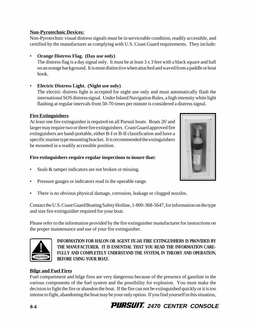
2470 CENTER CONSOLE
Non-Pyrotechnic Devices:Non-Pyrotechnic visual distress signals must be in serviceable condition, readily accessible, andcertified by the manufacturer as complying with U.S. Coast Guard requirements. They include:
• Orange Distress Flag. (Day use only)The distress flag is a day signal only. It must be at least 3 x 3 feet with a black square and ballon an orange background. It is most distinctive when attached and waved from a paddle or boathook.
• Electric Distress Light. (Night use only)The electric distress light is accepted for night use only and must automatically flash theinternational SOS distress signal. Under Inland Navigation Rules, a high intensity white lightflashing at regular intervals from 50-70 times per minute is considered a distress signal.
Fire ExtinguishersAt least one fire extinguisher is required on all Pursuit boats. Boats 26' andlarger may require two or three fire extinguishers. Coast Guard approved fireextinguishers are hand-portable, either B-I or B-II classification and have aspecific marine type mounting bracket. It is recommended the extinguishersbe mounted in a readily accessible position.
Fire extinguishers require regular inspections to insure that:
• Seals & tamper indicators are not broken or missing.
• Pressure gauges or indicators read in the operable range.
• There is no obvious physical damage, corrosion, leakage or clogged nozzles.
Contact the U.S. Coast Guard Boating Safety Hotline, 1-800-368-5647, for information on the typeand size fire extinguisher required for your boat.
Please refer to the information provided by the fire extinguisher manufacturer for instructions onthe proper maintenance and use of your fire extinguisher.
INFORMATION FOR HALON OR AGENT FE-241 FIRE EXTINGUISHERS IS PROVIDED BYTHE MANUFACTURER. IT IS ESSENTIAL THAT YOU READ THE INFORMATION CARE-FULLY AND COMPLETELY UNDERSTAND THE SYSTEM, IN THEORY AND OPERATION,BEFORE USING YOUR BOAT.
Bilge and Fuel FiresFuel compartment and bilge fires are very dangerous because of the presence of gasoline in thevarious components of the fuel system and the possibility for explosion. You must make thedecision to fight the fire or abandon the boat. If the fire can not be extinguished quickly or it is toointense to fight, abandoning the boat may be your only option. If you find yourself in this situation,
8-4
2470 CENTER CONSOLE
make sure all passengers have a life preserver on and go over the side and swim well upwind ofthe boat. This will keep you and your passengers well clear of any burning fuel that could bereleased and spread on the water as the boat burns or in the event of an explosion. When clear ofthe danger, check about and account for all those who were aboard with you. Give whateverassistance you can to anyone in need or in the water without a buoyant device. Keep everyonetogether in a group for morale and to aid rescue operations.
GASOLINE CAN EXPLODE. IN THE EVENT OF A FUEL COMPARTMENT OR BILGE FIRE,YOU MUST MAKE THE DIFFICULT DECISION TO FIGHT THE FIRE OR ABANDON THEBOAT. YOU MUST CONSIDER YOUR SAFETY, THE SAFETY OF YOUR PASSENGERS, THEINTENSITY OF THE FIRE AND THE POSSIBILITY OF AN EXPLOSION IN YOUR DECISION.
Sound Signaling Devices:The navigation rules require sound signals to be made under certain circumstances. Recreationalvessels are also required to sound fog signals during periods of reduced visibility. Therefore, youmust have some means of making an efficient sound signal that is audible for .5 nautical miles.
Navigation Lights:Recreational boats are required to display navigation lights between sunset and sunrise and otherperiods of reduced visibility (fog, rain, haze, etc.) Navigation lights are intended to keep othervessels informed of your presence and course. Your Pursuit is equipped with the navigation lightsrequired by the U.S. Coast Guard at the time of manufacture. It is up to you to make sure they areoperational and turned on when required.
8.6 Maximum Capacity Rating
Your boat is equipped with a “Maximum Capacities” plate, which is permanently attached to thecockpit near the helm. The plate indicates the maximum horsepower and load capacity for yourboat. Never exceed the limits dictated by the information provided on the capacity plate.
IT IS EXTREMELY DANGEROUS TO OVERLOAD OR OVERPOWER YOUR BOAT. BOATSTHAT ARE OVERLOADED OR OVERPOWERED CAN BECOME UNSTABLE OR DIFFICULTTO CONTROL. ALWAYS MAKE SURE THAT YOUR BOAT IS LOADED AND POWEREDWITHIN THE LIMITS SHOWN ON YOUR BOAT’S CAPACITY PLATE.
8.7 Additional Safety Equipment
Besides meeting the legal requirements, prudent boaters carry additional safety equipment. Thisis particularly important if you operate your boat offshore. You should consider the followingitems, depending on how you use your boat.
8-5
2470 CENTER CONSOLE
First AidIt is the operator's responsibility to be familiar with the proper first-aidprocedures and be able to care for minor injuries or illnesses of yourpassengers. In an emergency, you could be far from professionalmedical assistance. We strongly recommend that you be prepared byreceiving training in basic first aid and CPR. This can be donethrough classes given by the Red Cross or your local hospital.
Your boat should also be equipped with at least a simple marine first-aid kit and a first-aid manual.The marine first-aid kit should be designed for the marine environment and be well supplied. Itshould be accessible and each person on board should be aware of its location. As supplies areused, replace them promptly. Some common drugs and antiseptics may loose their strength orbecome unstable as they age. Ask a medical professional about the supplies you should carry andthe safe shelf life of prescription drugs or other medical supplies that may be in your first-aid kit.Replace questionably old supplies whether they have been used or not.
In many emergency situations, the Coast Guard can provide assistance in obtaining medical advicefor treatment of serious injuries or illness. If you are within VHF range of a Coast Guard Station,make the initial contact on channel 16 and follow their instructions.
Satellite EPIRBsEPIRBs (Emergency Position Indicating Radio Beacon) operate as part of a worldwide distresssystem. When activated, EPIRBs will send distress code homing beacons that allow Coast Guardaircraft to identify and find them quickly. The satellites that receive and relay EPIRB signals areoperated by the National Oceanic and Atmospheric Administration (NOAA) in the United States.The EPIRB should be mounted and registered according to the instructions provided with thebeacon, so that the beacon's unique distress code can be used to quickly identify the boat and owner.
Additional Equipment to Consider:
VHF Radio Life Raft Spare AnchorHeaving Line Fenders First Aid KitFlashlight Mirror SearchlightSunburn Lotion Tool Kit Ring BuoyWhistle or Horn Anchor Chart and CompassBoat Hook Spare Propeller Mooring LinesFood & Water Binoculars SunglassesMarine Hardware Extra Clothing Spare Parts
8-6
2470 CENTER CONSOLE
Chapter 9:Chapter 9:Chapter 9:Chapter 9:Chapter 9:
OPERATION
9.1 General
Before you start the engines on your Pursuit, you should have become familiar with the variouscomponent systems and their operation, and have performed a “Pre-Cruise System Check.” Athorough understanding of the component systems and their operation is essential to the properoperation of the boat. This manual and the associated manufacturers’ information is provided toenhance your knowledge of your Pursuit. Please read them carefully. Also read the book titled“Sportfish, Cruisers and Yachts,” included in your literature packet.
Your boat must have the necessary safety equipment on board and be in compliance with the U.S.Coast Guard, local and state safety regulations. There should be one Personal Floatation Device(PFD) for each person. Nonswimmers and small children should wear PFDs at all times. Youshould know and understand the “Rules of the Road” and have had an experienced operator briefyou on the general operation of your new boat. At least one other person should be instructed onthe proper operation of the boat in case the operator is suddenly incapacitated.
The operator is responsible for his safety and the safety of his passengers. When boarding orloading the boat, always step onto the boat, never jump. All passengers should be properly seatedwhenever the boat is operated above idle speed. Your passengers should not be allowed to sit onthe seat backs, gunnels, bows, transoms or on fishing seats whenever the boat is underway. Thepassengers should also be seated to properly balance the load and must not obstruct the operator'sview, particularly to the front.
Overloading and improper distribution of weight can cause the boat to become unstable and aresignificant causes of accidents. Know the weight capacity and horsepower rating of your boat. Donot overload or overpower your boat. Please refer to the Safety Equipment Chapter for moreinformation on the maximum capacity rating for your boat. Remember, the information statedon the capacity plate does not relieve the operator from the responsibility of using goodcommon sense and sound judgement in loading and operating the boat.
9.2 Rules of the Road
As in driving an automobile, there are a few rules you must know for safe boating operation. Thefollowing information describes the basic navigation rules and action to be taken by vessels in acrossing, meeting or overtaking situation while operating in inland waters. These are basicexamples and not intended to teach all the rules of navigation. For further information consult the“Navigation Rules” or contact the Coast Guard, Coast Guard Auxiliary, Department of Natural
9-1
2470 CENTER CONSOLE
Resources, or your local boat club. These organizations sponsor courses in boat handling,including rules of the road. We strongly recommend such courses. Books on this subject are alsoavailable from your local library.
SAILBOATS NOT UNDER POWER, PADDLE BOATS, VESSELS UNABLE TO MANEUVER,VESSELS ENGAGED IN COMMERCIAL FISHING AND OTHER VESSELS WITHOUT POWERHAVE THE RIGHT OF WAY OVER MOTOR POWERED BOATS. YOU MUST STAY CLEAROR PASS TO THE STERN OF THESE VESSELS. SAILBOATS UNDER POWER ARE CON-SIDERED MOTOR BOATS.
Crossing SituationsWhen two motor boats are crossing, the boat on the right has the right of way. The boat with theright of way should maintain its course and speed. The other vessel should slow down and permitit to pass. The boats should sound the appropriate signals.
Meeting Head-On or Nearly-So SituationsWhen two motor boats are approaching each other head-on or nearly head-on, neither boat has theright of way. Both boats should reduce their speed and turn to the right so as to pass port side toport side, providing enough clearance for safe passage. The boats should sound the appropriatesignals.
Overtaking SituationsWhen one motor boat is overtaking another motor boat, the boat that is being passed has the rightof way. The overtaking boat must make the adjustments necessary to provide clearance for a safepassage of the other vessel. The boats should sound the appropriate signals.
The General Prudential RuleIn obeying the Rules of the Road, due regard must be given to all dangers of navigation andcollision, and to any special circumstances, including the limitations of the vessels, which mayjustify a departure from the rules that is necessary to avoid immediate danger or a collision.
Navigation AidsAids to navigation are placed along coasts and navigable waters as guides to mark safe water andto assist mariners in determining their position in relation to land and hidden dangers. Each aid tonavigation is used to provide specific information. You should be familiar with these and any othermarkers used in your boating area.
STORMS AND WAVE ACTION CAN CAUSE BUOYS TO MOVE. YOU SHOULD NOT RELYON BUOYS ALONE TO DETERMINE YOUR POSITION.
9-2
2470 CENTER CONSOLE
9.3 Pre-Cruise System Check
Before Starting the Engines
• Check the weather forecast. Decide if the planned cruise can be made safely.
• Be sure all required documents are on board.
• Be sure all necessary safety equipment is on board and operative. This should include itemslike the running lights, spotlight, life saving devices, etc. Please refer to Chapter 8 for additionalinformation on safety equipment.
• Make sure you have signal kits and flare guns aboard, and they are current and in good operatingcondition.
• Be sure you have sufficient water and other provisions for the planned cruise.
• Leave a written message listing details of your planned cruise with a close friend ashore (FloatPlan). The float plan should include a description of your boat, where you intend to cruise, anda schedule of when you expect to arrive in the cruising area and when you expect to return.Keep the person informed of any changes in your plan to prevent false alarms. This informationwill tell authorities where to look and the type of boat to look for in the event you fail to arrive.
• Check the amount of fuel on board. Observe the “rule of thirds”: one third of the fuel for thetrip out, one third to return and one third in reserve. An additional 15% may be consumed inrough seas.
• Check the water separating fuel filters for water.
• Check the oil in the engine oil tanks.
• Set the battery selector switches as desired.
• Check the bilge water level. Look for other signs of potential problems. Monitor for the scentof fuel fumes.
• Test the automatic and manual bilge pump switches to make sure the system is workingproperly.
9-3
2470 CENTER CONSOLE
• Have a tool kit aboard. The kit should include the following basic tools:
Spark Plug Wrench HammerSpark Plug Gap Gauge Electrician’s TapeScrewdrivers Lubricating OilPliers JackknifeAdjustable Wrench Vise grip PliersNeedle Nose Pliers Wire Crimping ToolEnd Wrench Set Wire Connector Set
THERE MUST BE AT LEAST ONE PERSONAL FLOTATION DEVICE ONBOARD FOR EV-ERY PERSON ON BOARD AND ONE THROW-OUT FLOTATION DEVICE. CHECK THE U.S.COAST GUARD STANDARDS FOR THE CORRECT TYPE OF DEVICE FOR YOUR BOAT.
• Have the following spare parts on board:
Extra Light Bulbs Spark PlugsFuses and Circuit Breakers Flashlight and BatteriesDrain Plugs Engine OilPropeller Fuel FiltersPropeller Nuts Fuel Hose and Clamps
• Make sure all fire extinguishers are in position and in good operating condition.
• Be sure the shift control is in the neutral position.
• Be sure the emergency stop lanyard is attached to the operator and the stop switch.
VAPORIZING LIQUID EXTINGUISHERS GIVE OFF TOXIC FUMES; USE ONLY COAST GUARDAPPROVED FIRE EXTINGUISHERS .
9-4
2470 CENTER CONSOLE
9.4 Operating Your Boat
After Starting the Engines
TO REDUCE THE RISK OF A FIRE OR EXPLOSION, DO NOT START THE ENGINES WHENFUEL FUMES ARE PRESENT. FUEL FUMES ARE DANGEROUS AND HARMFUL TO YOURHEALTH.
• Visibly check the engines to be sure there are no apparent water, fuel or oil leaks.
• Check the operation of the engine cooling systems.
• Check the engine gauges. Make sure they are reading normally.
• Check the controls and steering for smooth and proper operation.
• Make sure all lines, cables, anchors, etc. for securing a boat are on board and in good condition.All lines should be coiled, secured and off the decks when underway.
• Have a safe cruise and enjoy yourself.
RememberWhen you operate a boat, you accept the responsibility for the boat, for the safety of passengers andfor others out enjoying the water.
• Alcohol and any drugs can severely reduce your reaction time and affect your better judgement.
• Alcohol severely reduces the ability to react to several different signals at once.
• Alcohol makes it difficult to correctly judge speed and distance, or track moving objects.
• Alcohol reduces night vision, and the ability to distinguish red from green.
YOU SHOULD NEVER OPERATE YOUR BOAT WHILE UNDER THE INFLUENCE OF AL-COHOL AND DRUGS.
• Avoid sea conditions that are beyond the skill and experience of you and your crew.
9-5
2470 CENTER CONSOLE
MAKE SURE ONE OTHER PERSON ON THE BOAT IS INSTRUCTED IN THE OPERATIONOF THE BOAT.
MAKE SURE THE BOAT IS OPERATED IN COMPLIANCE WITH ALL STATE AND LOCALLAWS GOVERNING THE USE OF A BOAT.
DO NOT OPERATE THE BOAT UNLESS IT IS COMPLETELY ASSEMBLED. KEEP ALLFASTENERS TIGHT. KEEP ADJUSTMENTS ACCORDING TO SPECIFICATIONS.
Before operating the boat for the first time, read the engine break-in procedures. The break-inprocedures are found in the owner’s manual for the engine. The manual is in the literature packet.
As different types of engines are used to power the boat, have the dealer describe the operatingprocedures for your boat. For more instructions on “How To Operate The Boat,” make sure youread the instructions given to you in the owner’s manual for the engines you have selected.
Note: For more instructions on safety, equipment and boat handling, enroll in one of theseveral free boating courses offered. For information on the courses offered in yourarea, call the “Boating Course Hotline,” 1-800-336-2628.
Note: If the drive unit hits an underwater object, stop the engine. Inspect the drive unit fordamage. If the unit is damaged, contact your dealer for a complete inspection andrepair of the unit.
To stop the boat, follow this procedure:
• Allow the engine to drop to the idle speed.
• Make sure the shifting levers are in the neutral position.
Note: If the engines have been run at high speed for a long period of time, allow the enginesto cool down by running the engines in the idle position for 3 to 5 minutes.
• Turn the ignition keys to the “Off” position.
• Raise the trim tabs to the full “UP” position.
9-6
2470 CENTER CONSOLE
After Operation
• If operating in saltwater, wash the boat and all equipment with soap and water. Flush t h eengines using freshwater. Please refer to the engine owner's manual for instructions on flushingyour outboard engines.
• Check the bilge area for debris and excess water.
• Fill the fuel tanks to near full to reduce condensation. Allow enough room in the tanks f o rthe fuel to expand without being forced out through the vent.
• Turn off all electrical equipment except the automatic bilge pumps.
• If you are going to leave the boat for a long period of time, put the battery main switches in the“Off” position and close all seacocks.
• Make sure the boat is securely moored.
TO PREVENT DAMAGE TO THE BOAT, CLOSE ALL SEA COCKS BEFORE LEAVING THEBOAT.
9.5 Grounding and Towing
If the boat should become disabled, or if another craft that is disabled requires assistance, great caremust be taken. The stress applied to a boat during towing may become excessive. Excessive stresscan damage the structure of the boat and create a safety hazard for those aboard.
Freeing a grounded vessel, or towing a boat that is disabled, requires specialized equipment andknowledge. Line failure and structural damage caused by improper towing have resulted in fatalinjuries. Because of this, we strongly suggest that these activities be left to those who have theequipment and knowledge, e.g., the U.S. Coast Guard or a commercial towing company, to safelyaccomplish the towing task.
THE MOORING CLEATS ON PURSUIT BOATS ARE NOT DESIGNED OR INTENDED TO BEUSED FOR TOWING PURPOSES. THESE CLEATS ARE SPECIFICALLY DESIGNED ASMOORING CLEATS FOR SECURING THE BOAT TO A DOCK, PIER, ETC. DO NOT USETHESE FITTINGS FOR TOWING OR ATTEMPTING TO FREE A GROUNDED VESSEL.
9-7 9-7
2470 CENTER CONSOLE
WHEN TOWING OPERATIONS ARE UNDERWAY, HAVE EVERYONE ABOARD BOTH VES-SELS STAY CLEAR OF THE TOW LINE AND SURROUNDING AREA. A TOW LINE THATSHOULD BREAK WHILE UNDER STRESS CAN BE VERY DANGEROUS, AND COULD CAUSESERIOUS INJURY OR DEATH.
RUNNING AGROUND OR STRIKING AN UNDERWATER OBSTRUCTION CAN RESULT IN SE-RIOUS INJURY TO PASSENGERS AND DAMAGE TO THE MOTOR OR BOAT. IF YOURBOAT SHOULD BECOME GROUNDED, DISTRIBUTE PERSONAL FLOTATION DEVICES ANDINSPECT THE BOAT FOR POSSIBLE DAMAGE. THOROUGHLY INSPECT THE BILGEAREA FOR SIGNS OF LEAKAGE. AN EXPERIENCED SERVICE FACILITY SHOULD CHECKYOUR UNDERWATER GEAR AT THE FIRST OPPORTUNITY. DO NOT CONTINUE TO USEYOUR BOAT IF THE CONDITION OF THE UNDERWATER EQUIPMENT IS QUESTIONABLE.
9.6 Water skiing
Your boat could be equipped for water skiing. If you have never driven skiers before, you shouldspend some hours as an observer and learning from an experienced driver. If you are anexperienced driver, you should take some time to become familiar with the boat and the way ithandles before pulling a skier. The driver should also know the skier’s ability and driveaccordingly. The following safety precautions should be observed while towing water skiers.
• Water ski only in safe areas, away from other boats and swimmers, out of channels, and in waterfree of underwater obstructions.
• Water ski only during daylight hours.
• Make sure that anyone who skis can swim. Do not allow people who cannot swim to waterski.
• Be sure that the skier is wearing a proper life jacket. A water skier is considered on board theboat and a Coast Guard approved life jacket is required. It is advisable and recommended fora skier to wear a flotation device designed to withstand the impact of hitting the water at highspeed.
• Always carry a second person on board to observe the skier so that your full attention can begiven to the safe operation of the boat.
• Approach a skier in the water from the downwind side and be certain to stop the motion of theboat and your motor before coming in close proximity to the skier. The skier should also bekept on the helm side of the boat so the operator can keep the skier in sight at all times.
9-8
2470 CENTER CONSOLE
• Give immediate attention to a fallen skier. A fallen skier is very hard to see by other boats andis extremely vulnerable. When a skier falls, be prepared to immediately turn the boat and returnto the skier. Never leave a fallen skier alone in the water for any reason.
For additional information on water skiing, including hand signals and water skiing manuals,contact the American Water Skiing Association in Winter Haven, Florida, 813-324-4341.
MOVING PROPELLERS ARE DANGEROUS. THEY CAN CAUSE DEATH, LOSS OF LIMBS,OR OTHER SEVERE INJURY. DO NOT USE THE SWIM PLATFORM OR SWIM LADDERWHILE THE ENGINE IS RUNNING. STOP THE ENGINE IF DIVERS, SWIMMERS OR SKI-ERS ARE ATTEMPTING TO BOARD. ALWAYS REMOVE AND PROPERLY STORE THELADDER BEFORE STARTING THE ENGINE.
9.7 Fishing
Fishing can be very exciting and distracting for the operator when the action gets intense. You mustalways be conscious of the fact that your primary responsibility is the safe operation of your boatand the safety of your passengers and other boats in the area.
You must always make sure the helm is properly manned and is never left unattended while trolling.
If you are fishing in an area that is crowded with other fishing boats, it may be difficult to followthe rules of the road. This situation can become especially difficult when most boats are trolling.Being courteous and exercising good common sense is essential. Avoid trying to assert your rightof way and concentrate on staying clear and preventing tangled or cut lines and other unpleasantencounters with other boats. Also keep in mind that fishing line wrapped around your propellershaft can damage the seals in the outboard lower unit.
9.8 Trailering Your Boat
f you trailer your boat, make sure that your tow vehicle is capable of towing the weight of the trailer,boat and equipment and the weight of the passengers and equipment inside the vehicle. This mayrequire that the tow vehicle be specially equipped with a larger engine, transmission, brakes andtrailer tow package.
The boat trailer is an important part of your boating package. The trailer should be matched to yourboat's weight and hull. Using a trailer with a capacity too low will be unsafe on the road and causeabnormal wear. A trailer with a capacity too high, can damage the boat. Contact your dealer toevaluate your towing vehicle and hitch, and to make sure you have the correct trailer for your boat.
9-9
2470 CENTER CONSOLE
Important Note:Your Pursuit is a heavy boat and care must be taken when selecting the trailer. Werecommend that you use a bunk style trailer that incorporates a combination of heavy dutyrollers, to support the keel and long bunks running under and parallel to the stringers tosupport the hull. Avoid using a full roller trailer that does not have bunks. Roller trailershave a tendency to put extreme pressure points on the hull, especially on the lifting strakes,and have damaged boats. The situation is worse during launching and haul out. Damageresulting from improper trailer support or the use of a full roller trailer will not be coveredby the Pursuit Warranty.
Note: Contact your dealer to evaluate your towing vehicle and hitch, and to make sure youhave the correct trailer for your boat.
The following safety tips and a book titled “Sportfish, Cruisers, Yachts - Owner's Manual,”included in your literature packet, provide additional information you should know before traileringyour boat.
Choosing and setting up a trailer:
• Make sure the trailer is a match for your boat’s weight and hull design. More damage can bedone to a boat by the stresses of road travel than by normal water operation. A boat hull isdesigned to be supported evenly by water. So, when it is transported on a trailer it should besupported structurally as evenly across the hull as possible allowing for even distribution of theweight of the hull, engine and equipment.
• Make sure the trailer bunks and rollers properly support the hull and do not put pressure on thelifting strakes. The rollers and bunks must be kept in good condition to prevent scratching andgouging of the hull.
• The capacity rating of the trailer should be greater than the combined weight of the boat, motor,and equipment. The gross vehicle weight rating must be shown on the trailer. Make sure theweight of the boat, engine, gear and trailer is not more than the gross vehicle weight rating.
• Make sure the boat is securely fastened on the trailer to prevent movement between the boatand trailer. The bow eye on the boat should be secured with a rope, chain or turnbuckle inaddition to the winch cable. Additional straps may be required across the beam of the boat.
Note: Your dealer can provide instructions on how to load, fasten and launch your boat.
BOATS HAVE BEEN DAMAGED BY TRAILERS THAT DO NOT PROPERLY SUPPORT THEHULL. ALWAYS MAKE SURE THE TRAILER BUNKS AND ROLLERS ARE ADJUSTED SOTHEY ARE NOT PUTTING EXCESSIVE PRESSURE ON THE LIFTING STRAKES AND AREPROVIDING ENOUGH SUPPORT FOR THE HULL. HULL DAMAGE RESULTING FROM IM-PROPER TRAILER SUPPORT IS NOT COVERED BY THE PURSUIT WARRANTY.
9-10
2470 CENTER CONSOLE
Before Going Out On The Highway:
• The BIMINI TOP, SIDE CURTAINS, CLEAR CONNECTOR, BACK DROP and AFTCURTAIN must be removed when trailering. Canvas enclosures are not designed to withstandthe extreme wind pressure encountered while trailering and will be damaged. Always removeand properly store the enclosure before trailering your boat.
• Make sure the tow BALL and COUPLER are the same size and bolts nuts are tightly secured.
• The COUPLER MUST BE COMPLETELY OVER THE BALL and the LATCHINGMECHANISM LOCKED DOWN.
• Make sure the TRAILER IS LOADED EVENLY from front to rear as well as side to side andhas the correct weight on the hitch. Too much weight on the hitch will cause the rear of the towvehicle to drag and may make steering more difficult. Too little weight on the hitch will causethe rig to fishtail and will make controlling the tow vehicle difficult. Contact your Pursuit dealeror the trailer manufacturer for the correct weight on the hitch for your trailer.
• The SAFETY CHAINS must be attached crisscrossing under the coupler to the frame of thetow vehicle. If the ball was to break, the trailer would follow in a straight line and prevent thecoupler from dragging on the road. Make sure the trailer emergency brake cable or chain is alsoinstalled to the tow vehicle frame.
• Make sure the LIGHTS on the trailer function properly.
• CHECK THE BRAKES. On a level parking area roll forward and apply the brakes severaltimes at increasing speeds to determine if the brakes on the tow vehicle and trailer are workingproperly.
• Make sure the tow vehicle has SIDE VIEW MIRRORS that are large enough to provide anunobstructed rear view on both sides of the vehicle.
• CHECK THE TIRES and WHEEL BEARINGS.
MAKE SURE YOUR TOWING VEHICLE AND TRAILER ARE IN COMPLIANCE WITH ALLSTATE AND LOCAL LAWS. CONTACT YOUR STATE MOTOR VEHICLE BUREAU FORLAWS GOVERNING THE TOWING OF TRAILERS.
9-11

2470 CENTER CONSOLE
THIS PAGE WAS LEFT BLANKINTENTIONALLY
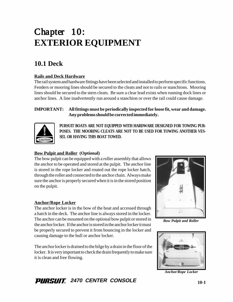
2470 CENTER CONSOLE
Chapter 10:Chapter 10:Chapter 10:Chapter 10:Chapter 10:
EXTERIOR EQUIPMENT
10.1 Deck
Rails and Deck HardwareThe rail system and hardware fittings have been selected and installed to perform specific functions.Fenders or mooring lines should be secured to the cleats and not to rails or stanchions. Mooringlines should be secured to the stern cleats. Be sure a clear lead exists when running dock lines oranchor lines. A line inadvertently run around a stanchion or over the rail could cause damage.
IMPORTANT: All fittings must be periodically inspected for loose fit, wear and damage.Any problems should be corrected immediately.
PURSUIT BOATS ARE NOT EQUIPPED WITH HARDWARE DESIGNED FOR TOWING PUR-POSES. THE MOORING CLEATS ARE NOT TO BE USED FOR TOWING ANOTHER VES-SEL OR HAVING THIS BOAT TOWED.
Bow Pulpit and Roller (Optional)The bow pulpit can be equipped with a roller assembly that allowsthe anchor to be operated and stored at the pulpit. The anchor lineis stored in the rope locker and routed out the rope locker hatch,through the roller and connected to the anchor chain. Always makesure the anchor is properly secured when it is in the stored positionon the pulpit.
Anchor/Rope LockerThe anchor locker is in the bow of the boat and accessed througha hatch in the deck. The anchor line is always stored in the locker.The anchor can be mounted on the optional bow pulpit or stored inthe anchor locker. If the anchor is stored in the anchor locker it mustbe properly secured to prevent it from bouncing in the locker andcausing damage to the hull or anchor locker.
The anchor locker is drained to the bilge by a drain in the floor of thelocker. It is very important to check the drain frequently to make sureit is clean and free flowing.
Anchor/Rope Locker
Bow Pulpit and Roller
10-1
2470 CENTER CONSOLE
THE ANCHOR MUST BE POSITIONED SO IT DOES NOT REST AGAINST THE HULL SIDESAND BE PROPERLY SECURED AT ALL TIMES WHEN IT IS STORED IN THE ANCHOR/ROPE LOCKER. A LOOSE ANCHOR IN THE ANCHOR LOCKER WILL BOUNCE AND CANDAMAGE THE BOAT. DAMAGE RESULTING FROM THE ANCHOR BOUNCING IN THEANCHOR LOCKER IS NOT COVERED BY THE PURSUIT WARRANTY.
Windlass (Optional)The optional windlass is mounted to the deck near the rear of the pulpit above the rope locker. Theanchor is stored on the pulpit and is raised and lowered by the windlass. The anchor line is storedin the rope locker and routed out through the windlass to the anchor chain.
The anchor is lowered by releasing the anchor from the cleat or chain binder on the pulpit andoperating a “down” control at the helm. The windlass control switch is activated by a safety switchor breaker panel located next to the windlass switch. Turn the safety switch or breaker to “ON”to activate the windlass control and turn it to “OFF” whenever the windlass is not in use.
After the anchor is set, the windlass must not be left to take the entire force from the anchor line.Boats lying to their anchor in a high swell or heavy weather conditions will snub on the line. Thiscan cause slippage or apply excessive loads to the windlass. The line should be made fast to a bowcleat to relieve the load on the windlass.
The anchor is hauled in by releasing the line from the bow cleat and operating the “up” control atthe helm. Once the anchor is retrieved, independently secure the anchor to the chain binder or acleat to prevent it from being accidentally released. This is especially important while the boat isunder way.
The windlass manufacturer provides an owner’s manual with its product. It is extremely importantthat you read the manual and become familiar with the proper care and operation of the windlass.
A WINDLASS MUST BE USED WITH CARE. IT IS EXTREMELY IMPORTANT THAT YOUREAD THE OWNER’S MANUAL AND BECOME FAMILIAR WITH THE SAFETY INSTRUC-TIONS AND PROPER OPERATION OF THE WINDLASS BEFORE USING IT WITH YOURBOAT. ALWAYS ENSURE THAT LIMBS, FINGERS, HAIR AND CLOTHING ARE KEPTCLEAR OF THE WINDLASS AND ANCHOR LINE DURING OPERATION.
DO NOT USE A WINDLASS AS A SOLE MEANS OF SECURING AN ANCHOR IN THE BOWPULPIT. ALWAYS SECURE THE ANCHOR LINE TO A CLEAT OR CHAIN BINDER BE-FORE OPERATING YOUR BOAT.
10-2
2470 CENTER CONSOLE
10.2 Hull
Swim PlatformYour Pursuit is equipped with an integral swim platform and engine mounting system located inthe stern of the boat. There are two inspection deck plates in the transom engine well to provideaccess to the stern bilge and engine mounting bolts. Always make sure these plates are securebefore operating your boat.
Boarding Ladder (Optional)The optional boarding ladder is mounted to the rear of the stern bait and tackle rigging station whenit is in the stored position. To use the ladder, remove it from the storage clips and slide the studsinto the special bracket on the port side of the transom. The ladder floats and must be secured inthe boarding position by turning the cam lock on the ladder so it catches the bottom of the transomladder bracket. The ladder must be removed from the transom bracket and properly secured to thestorage clips before starting the engine(s).
MOVING PROPELLERS ARE DANGEROUS. THEY CAN CAUSE DEATH, LOSS OF LIMBS,OR OTHER SEVERE INJURY. DO NOT USE THE SWIM PLATFORM OR SWIM LADDERWHILE THE ENGINE(S) ARE RUNNING. STOP THE ENGINE(S) IF DIVERS OR SWIMMERSARE ATTEMPTING TO BOARD. ALWAYS REMOVE AND PROPERLY STORE THE LAD-DER BEFORE STARTING THE ENGINE(S).
10.3 Cockpit Equipment
IN CERTAIN CONDITIONS, OPEN EXTERIOR DOORS AND HATCHES THAT ARE NOT SE-CURED PROPERLY CAN SLAM CLOSED UNEXPECTEDLY AND CAUSE INJURY TO PAS-SENGERS OR DAMAGE TO THE BOAT. MOST DOORS AND HATCHES ARE EQUIPPEDWITH SPECIAL FASTENERS, HATCH LIFTERS, OR SNAPS AND/OR STRAPS, TO SECURETHEM IN THE OPEN POSITION. ALWAYS MAKE SURE THAT THESE HATCHES ANDDOORS ARE PROPERLY SECURED WHENEVER THEY ARE IN THE OPEN POSITION.
Bow Storage Compartment and FishboxThere is a large fishbox located under the port bow hatch. This is drained overboard by gravity andcan be used as a fishbox or storage compartment. When this box is used as a fishbox, it should bedrained and cleaned after each use. A large storage compartment is located under the starboard bowhatch. This compartment is drained into the bilge and is intended for dunnage.
Leaning Post/BaitwellThe leaning post/baitwell is equipped with rod holders, a leaning post cushion, and a circulatinglivewell. The livewell is supplied by a raw water aerator pump and drains overboard. Refer toChapter 6 for additional information on the raw water system.
10-3
2470 CENTER CONSOLE
Stern Bait and Tackle Rigging StationThe stern bait and tackle rigging station is equipped with a sink, removable cutting board, fishbox,tackle locker and rigged bait storage area. The sink is plumbed to the freshwater system. Refer toChapter 6 for additional information on the raw water system.
The tackle locker is below the fishbox and is removable to allow access to the bilge, Y-valve, andthe port battery. To remove the tackle locker, open the door and remove the top drawer. Removethe quick release pin on the upper port side of the tackle locker and slide the locker forward out ofthe frame.
Transom DoorA transom door is incorporated into the rigging station. The transom door should only be openedwhen the boat is not in motion. The door must be latched in either the full “OPEN” or full“CLOSED” position. Never leave the transom door unlatched.
Note: Periodically inspect the transom door fittings for wear, damage, or loose fit. Anyproblems should be inspected and corrected immediately.
THE TRANSOM DOOR SHOULD BE CLOSED AND PROPERLY LATCHED WHENEVER THEENGINE(S) ARE RUNNING. NEVER OPEN THE TRANSOM DOOR WHILE UNDERWAY ORIN ROUGH SEA CONDITIONS. IN CERTAIN SITUATIONS, AN OPEN TRANSOM DOORCOULD ALLOW A SUBSTANTIAL AMOUNT OF WATER TO ENTER THE COCKPIT CRE-ATING A POTENTIALLY DANGEROUS CONDITION.
OPERATING THE BOAT UNDER POWER WITH THE TRANSOM DOOR AND GATE OPENMAY ALLOW PERSONS TO FALL OVERBOARD AND INTO BOAT PROPELLERS OR TOBE LOST IN OPEN WATER. ALWAYS CHECK TO MAKE SURE THE TRANSOM DOORAND GATE IS PROPERLY CLOSED AND LATCHED BEFORE STARTING THE ENGINES ANDNEVER OPERATE THE BOAT UNDER POWER WITH THE TRANSOM DOOR AND GATEOPEN.
10.4 Center Console
Helm and Electronics LockerThe helm and engine controls are located on the rear of the center console. Molded-in electronicsstorage is located forward of the engine controls.
The top section of the console is hinged and opens to provide access to service the helm equipmentor to install electronics. To open the helm portion of the console, release the clamps on the frontof the console. The front of the console can then be lifted to expose the underside of the helm. Astrap holds the helm in the open position and prevents it from opening too far. Always make surethe helm station clamps are properly secured when the helm is closed.
10-4
2470 CENTER CONSOLE
If a T-top is installed, it must be designed with four legs that are bolted to the cockpit sole near thefront and rear sides of the center console. There are aluminum plates laminated in the cockpit solethat can be drilled and tapped to secure the T-top leg bases. Both front and rear legs should alsohave brackets that are thru bolted to the console just below the hinged helm section to provideadditional stiffening for the T-top. Avoid a T-top that is designed to mount only on the centerconsole because it will cause the excessive flexing to the console and cockpit sole which will resultin stress cracks and fractures in the fiberglass . If you have any questions about installing a T-topon your boat, please contact your dealer or the Pursuit Customer Relations Department.
ALWAYS MAKE SURE THE HELM STATION CLAMPS ARE PROPERLY SECURED BEFOREOPERATING OR TRAILERING YOUR BOAT. IF THE HELM STATION IS NOT PROPERLYSECURED, IT COULD OPEN UNEXPECTEDLY AND DAMAGE THE BOAT OR CAUSE LOSSOF CONTROL.
UNDER NO CIRCUMSTANCES SHOULD THE HELM BE OPENED WHEN THE ENGINE(S)ARE RUNNING. IN SOME SITUATIONS IT IS POSSIBLE TO ACCIDENTALLY ENGAGE THEENGINE SHIFT AND THROTTLE CONTROL INTO GEAR AS THE HELM IS OPENING. THISCOULD RESULT IN LOSS OF CONTROL, DAMAGE TO THE BOAT, AND INJURY TO PAS-SENGERS.
Head CompartmentThe head compartment is located in the console. A door in the starboard side of the consoleprovides access to the head. The porta potti or head and the freshwater pump are among theequipment mounted in this compartment. Refer to Chapter 11 for information on the equipmentin the head compartment.
Console CoolerA molded insulated cooler is installed under the front seat of the console. The cooler drains to thecockpit sole through a fitting in the side of the console. The cooler should be cleaned thoroughlyafter each use.
10-5

2470 CENTER CONSOLE
THIS PAGE WAS LEFT BLANKINTENTIONALLY
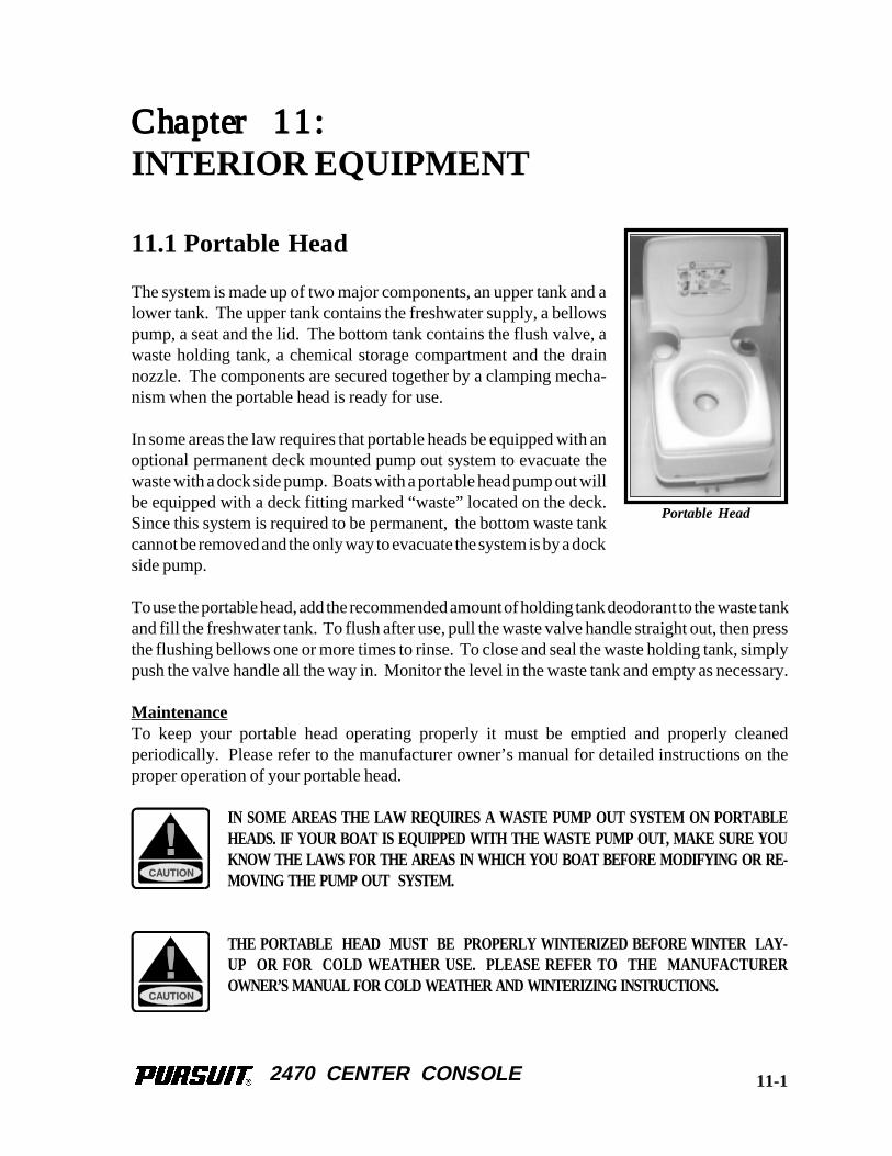
2470 CENTER CONSOLE
Chapter 11:Chapter 11:Chapter 11:Chapter 11:Chapter 11:
INTERIOR EQUIPMENT
11.1 Portable Head
The system is made up of two major components, an upper tank and alower tank. The upper tank contains the freshwater supply, a bellowspump, a seat and the lid. The bottom tank contains the flush valve, awaste holding tank, a chemical storage compartment and the drainnozzle. The components are secured together by a clamping mecha-nism when the portable head is ready for use.
In some areas the law requires that portable heads be equipped with anoptional permanent deck mounted pump out system to evacuate thewaste with a dock side pump. Boats with a portable head pump out willbe equipped with a deck fitting marked “waste” located on the deck.Since this system is required to be permanent, the bottom waste tankcannot be removed and the only way to evacuate the system is by a dockside pump.
To use the portable head, add the recommended amount of holding tank deodorant to the waste tankand fill the freshwater tank. To flush after use, pull the waste valve handle straight out, then pressthe flushing bellows one or more times to rinse. To close and seal the waste holding tank, simplypush the valve handle all the way in. Monitor the level in the waste tank and empty as necessary.
MaintenanceTo keep your portable head operating properly it must be emptied and properly cleanedperiodically. Please refer to the manufacturer owner’s manual for detailed instructions on theproper operation of your portable head.
IN SOME AREAS THE LAW REQUIRES A WASTE PUMP OUT SYSTEM ON PORTABLEHEADS. IF YOUR BOAT IS EQUIPPED WITH THE WASTE PUMP OUT, MAKE SURE YOUKNOW THE LAWS FOR THE AREAS IN WHICH YOU BOAT BEFORE MODIFYING OR RE-MOVING THE PUMP OUT SYSTEM.
THE PORTABLE HEAD MUST BE PROPERLY WINTERIZED BEFORE WINTER LAY-UP OR FOR COLD WEATHER USE. PLEASE REFER TO THE MANUFACTUREROWNER’S MANUAL FOR COLD WEATHER AND WINTERIZING INSTRUCTIONS.
Portable Head
11-1
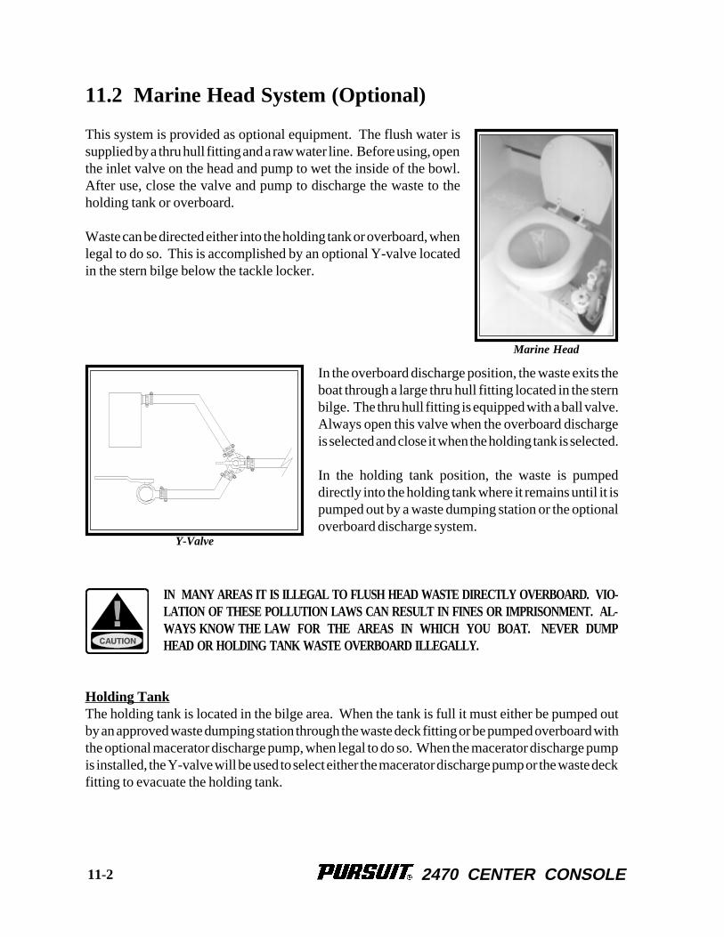
2470 CENTER CONSOLE
11.2 Marine Head System (Optional)
This system is provided as optional equipment. The flush water issupplied by a thru hull fitting and a raw water line. Before using, openthe inlet valve on the head and pump to wet the inside of the bowl.After use, close the valve and pump to discharge the waste to theholding tank or overboard.
Waste can be directed either into the holding tank or overboard, whenlegal to do so. This is accomplished by an optional Y-valve locatedin the stern bilge below the tackle locker.
In the overboard discharge position, the waste exits theboat through a large thru hull fitting located in the sternbilge. The thru hull fitting is equipped with a ball valve.Always open this valve when the overboard dischargeis selected and close it when the holding tank is selected.
In the holding tank position, the waste is pumpeddirectly into the holding tank where it remains until it ispumped out by a waste dumping station or the optionaloverboard discharge system.
IN MANY AREAS IT IS ILLEGAL TO FLUSH HEAD WASTE DIRECTLY OVERBOARD. VIO-LATION OF THESE POLLUTION LAWS CAN RESULT IN FINES OR IMPRISONMENT. AL-WAYS KNOW THE LAW FOR THE AREAS IN WHICH YOU BOAT. NEVER DUMPHEAD OR HOLDING TANK WASTE OVERBOARD ILLEGALLY.
Holding TankThe holding tank is located in the bilge area. When the tank is full it must either be pumped outby an approved waste dumping station through the waste deck fitting or be pumped overboard withthe optional macerator discharge pump, when legal to do so. When the macerator discharge pumpis installed, the Y-valve will be used to select either the macerator discharge pump or the waste deckfitting to evacuate the holding tank.
Y-Valve
Marine Head
11-2
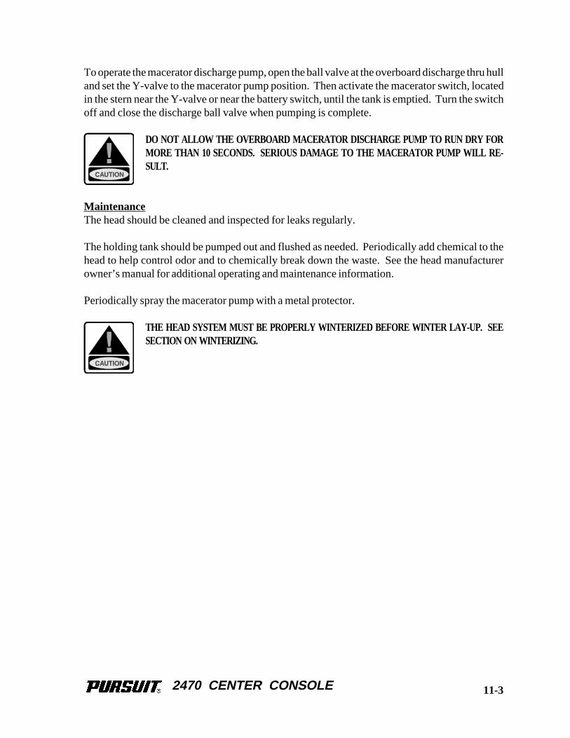
2470 CENTER CONSOLE
To operate the macerator discharge pump, open the ball valve at the overboard discharge thru hulland set the Y-valve to the macerator pump position. Then activate the macerator switch, locatedin the stern near the Y-valve or near the battery switch, until the tank is emptied. Turn the switchoff and close the discharge ball valve when pumping is complete.
DO NOT ALLOW THE OVERBOARD MACERATOR DISCHARGE PUMP TO RUN DRY FORMORE THAN 10 SECONDS. SERIOUS DAMAGE TO THE MACERATOR PUMP WILL RE-SULT.
MaintenanceThe head should be cleaned and inspected for leaks regularly.
The holding tank should be pumped out and flushed as needed. Periodically add chemical to thehead to help control odor and to chemically break down the waste. See the head manufacturerowner’s manual for additional operating and maintenance information.
Periodically spray the macerator pump with a metal protector.
THE HEAD SYSTEM MUST BE PROPERLY WINTERIZED BEFORE WINTER LAY-UP. SEESECTION ON WINTERIZING.
11-3

2470 CENTER CONSOLE
THIS PAGE WAS LEFT BLANKINTENTIONALLY
2470 CENTER CONSOLE
Chapter 12:Chapter 12:Chapter 12:Chapter 12:Chapter 12:
ROUTINE MAINTENANCE
12.1 Exterior Hull and Deck
Hull Cleaning-Below The Water LineWhen the boat is removed from the water, clean the outer bottom surface immediately. Algae,grass, dirt and other marine growth is easier to remove while the hull is still wet. Use a pressurecleaner or a hard bristle brush to clean the surface.
Bottom PaintingIf the boat is to be left in saltwater for extended periods, the hull must be protected from marinegrowth by antifouling paint. Because of variations in water temperature, marine growth, andpollution in different regions, your dealer and/or a qualified boat yard in your area should beconsulted when deciding what bottom paint system to apply to your hull. This is extremelyimportant as pollution and marine growth can damage fiberglass hulls.
SANDING OR SANDBLASTING THE HULL BOTTOM WILL DAMAGE THE FIBERGLASS.USE ONLY STANDARD ANTIFOULING PAINTS AND FIBERGLASS WAX REMOVERS ANDPRIMERS RECOMMENDED BY THE ANTIFOULING PAINT MANUFACTURER WHEN PRE-PARING THE HULL FOR BOTTOM PAINT. SANDING OR SANDBLASTING AND THE USEOF A COATING OTHER THAN STANDARD ANTIFOULING PAINT OR EPOXY BARRIERCOATINGS ARE NOT RECOMMENDED AND WILL VOID THE FIVE YEAR HULL BLISTERWARRANTY.
Most bottom paints require some maintenance. Proper maintenance is especially important whenthe boat is in saltwater and not used for extended periods or after dry storage. If the hull bottomhas been painted with antifouling paint, contact your dealer or the paint manufacturer for therecommended maintenance procedures.
ZincsSacrificial zinc anodes are installed on the outboard engines and should be installed on the trim tabsif the boat is to be left in the water. The anodes are less noble than copper based alloys and aluminumand will deteriorate first, protecting the more noble underwater hardware against galvaniccorrosion. Zincs should be checked monthly and changed when they are 75% of their original size.When replacing the anodes, make sure the contact surfaces are clean, shiny metal and free of paintand corrosion. Never paint over the anode.
12-1
2470 CENTER CONSOLE
Fiberglass Gelcoat SurfacesNormal maintenance requires only washing with mild soap and water. A stiff brush can be usedon the nonskid areas. Kerosene or commercially prepared products will remove oil and tar whichcould be a problem on trailered boats. Harsh abrasive and chemical cleaners are not recommendedbecause they can damage or dull the gelcoat, reducing its life and making it more susceptible tostains. When the boat is used in saltwater, it should be washed thoroughly with soap and water aftereach use.
At least once a season, wash and wax all exposed fiberglass surfaces. Use a high quality automotiveor boat wax. Follow the procedure recommended by the wax manufacturer. The washing andwaxing of your boat will have the same beneficial effects as they have on an automobile finish. Thewax will fill minute scratches and pores thus helping to prevent soiling and will extend the life ofthe gelcoat.
After the boat is exposed to the direct sunlight for a period of time, the color in the gelcoat tendsto fade, dull or chalk. A heavier buffing is required to bring the gelcoat back to its original luster.For power cleaning, use a light cleaner such as Mirror Glaze # 1®. To clean the boat by hand, usea heavier automotive cleaner. Before cleaning the surfaces, read the instructions given with thecleaner. After cleaning the surfaces, apply wax, and polish all fiberglass surfaces except thenonskid areas.
If the fiberglass should become damaged and need repair, contact your dealer for an authorizedrepair person to do the work.
DO NOT WAX NONSKID AREAS AS THIS COULD MAKE THEM SLIPPERY AND CONSE-QUENTLY INCREASE THE POSSIBILITY OF INJURY.
Stainless Steel HardwareWhen using the boat in saltwater, the hardware should be washed with soap and water after eachuse. When your boat is used in a corrosive environment such as saltwater, water with a high sulfurcontent, or polluted water, the stainless steel will periodically develop surface rust stains. This isperfectly normal under these conditions. The stainless can normally be cleaned and protected byusing a high quality boat or automotive wax or a commercial metal cleaner and protectant.
UNDER NO CIRCUMSTANCES SHOULD ANY ABRASIVE MATERIALS SUCH AS SANDPAPER,BRONZE WOOL, OR STEEL WOOL BE USED ON STAINLESS STEEL. DAMAGE TO THEHARDWARE WILL RESULT.
12-2
2470 CENTER CONSOLE
Anodized Aluminum SurfacesAnodized aluminum should be washed periodically with soap and water to keep it clean. If the boatis used in saltwater or polluted water, the aluminum should be washed with soap and water aftereach use. Saltwater allowed to remain on anodized aluminum will penetrate the anodized coatingand attack the aluminum.
T-tops, tops with aluminum frames, and towers with canvas and/or fiberglass tops require specialattention to the anodized aluminum just below the top. This area is subject to salt build up from saltycondensation and sea spray. It is also frequently overlooked when the boat is washed and will notbe rinsed by the rain. Consequently, the aluminum just below the top is more likely to become pittedthan the exposed aluminum on the structure. Make sure the aluminum in this area is washedfrequently with soap and water and rinsed thoroughly. Pay particular attention to places where thetop material and lacing contact the frame. Once a month coat the entire frame with a metal protectormade for anodized aluminum to protect against pitting and corrosion caused by the harsh effectsof salt water. The anodized aluminum used on your Pursuit was coated with a metal protector calledAluma Guard at the factory. Aluma Guard is a nonabrasive marine metal protector that protectsanodized aluminum, stainless steel, brass, and chrome. It also protects color anodizing from fadingand discoloring due to harmful ultraviolet rays. It is available from Rupp Marine Inc., 4761 AnchorAvenue, P.O. Drawer F, Port Salerno, FL 34992.
ONE DRAWBACK TO ALUMA GUARD AND OTHER METAL PROTECTORS IS THAT THEYCAN MAKE THE METAL SLIPPERY. THEREFORE, THEY SHOULD BE NOT BE USEDON TOWER LADDERS, STEERING WHEELS AND OTHER AREAS WHERE A GOOD GRIPAND SURE FOOTING IS IMPORTANT.
Stains can be removed with a metal polish or fine polishing compound. To minimize corrosion,use a caulking compound to bed hardware and fasteners mounted to aluminum fabrications. If theanodized coating is badly scratched it can be touched up with paint. With proper care, anodizedaluminum will provide many years of service.
Chrome HardwareUse a good chrome cleaner and polish on all chrome hardware.
Acrylic Plastic GlassAcrylic glass scratches easily. Use a soft cloth and mild soap and water to clean acrylic. Solventsand products containing ammonia can permanently damage acrylic. A coat of automotive or boatwax is beneficial to protect the surface. Do not use the following on acrylic:
Abrasive cleaners AcetoneSolvents AlcoholGlass cleaners Cleaners containing ammonia
12-3
2470 CENTER CONSOLE
EnginesProper engine maintenance is essential to the proper performance and reliability of your outboardengines. Maintenance schedules and procedures are outlined in your engine owner's manual. Theyshould be followed exactly.
If the boat is used in saltwater, flush the cooling systems after each daily use. To flush the systemswhen the boat is out of the water, follow the procedure outlined in your engine owner's manual.
The age of gasoline can affect engine performance. Chemical changes occur as the gasoline agesthat can cause deposits and varnish in the fuel system as well as reduce the octane rating of the fuel.Severely degraded fuel can damage the engine and boat fuel tank and lines. Therefore, if your boatis not being run enough to require at least one full tank of fresh fuel a month, a fuel stabilizer shouldbe added to the gasoline to protect the fuel from degradation. Your dealer or the enginemanufacturer can provide additional information on fuel degradation and fuel stabilizers recom-mended for your engine.
Avoid using fuels with alcohol additives. Gasoline that is an alcohol blend will absorb moisturefrom the air which can reach such concentrations that "phase separation" can occur whereby thewater and alcohol mixture becomes heavy enough to settle out of the gasoline to the bottom of thetank. Since the fuel pick up tube is very near the bottom of the tank, phase separation can causethe engine to run very poorly or not at all. This condition is more severe with methyl alcohol andwill worsen as the alcohol content increases. Water or a jelly like substance in the fuel filters arean indication of possible phase separation from the use of alcohol blended fuels.
If the boat is used in saltwater, flush the cooling system after each daily use. To flush the systemwhen the boat is out of the water, follow the procedure outlined in your engine owner's manual.
12.2 Upholstery, Canvas and Enclosures
Vinyl UpholsteryThe vinyl upholstery used on the exterior seats and bolsters, and for the headliner in some cabins,should be cleaned periodically with soap and water. Any stain, spill or soiling should be cleanedup promptly to prevent the possibility of permanent staining. When cleaning, always rub gently.Avoid using products containing ammonia, powdered abrasive cleaners, steel wool, ink, strongsolvents, acetone and lacquer solvents or other harsh chemicals as they can cause permanentdamage or shorten the life of vinyl. Never use steam heat, heat guns or hair dryers on vinyl.
Stronger cleaners, detergents and solvents may be effective in stain removal, but can cause eitherimmediate damage or slow deterioration. Lotions, sun tan oil, waxes and polishes, etc., containsoils and dyes that can cause stiffening and staining of vinyls.
• Dry soil, dust and dirt - Remove with a soft cloth.• Dried on dirt - Wash with a soft cloth dampened with water.
12-4
2470 CENTER CONSOLE
• Variations in surface gloss - Wipe with a water dampened soft cloth and allow to air dry.• Stubborn dirt - Wash with a soft cloth dampened with Ivory Flakes® and water. Rinse with
clean water.• Stubborn spots and stains - Spray with either Fantastik Cleaner® or Tannery Car Care Cleaner®
and rub with a soft cloth. Rinse with clean water.• Liquid spills - Wipe immediately with a clean absorbent cloth. Rinse with clean water.• Food grease and oily stains - Spray immediately using either Fantastik Cleaner® or Tannery
Car Care Cleaner®, wiping with a soft cloth. Take care not to extend the area of contaminationbeyond its original boundary. Rinse with clean water.
A vinyl protector will protect and extend the life of vinyl. One drawback to vinyl protectors is thatthey may make the vinyl slippery. You may find this to be undesirable in some applications.
Acrylic CanvasAcrylic canvas should be cleaned periodically by using a mild soap and water. Scrub lightly andrinse thoroughly to remove the soap. Do not use detergents. The top or accessories should neverbe folded or stored wet.
After several years, the acrylic canvas may lose some of its ability to shed water. If this occurs, washthe fabric and treat it with a commercially available water proofing designed for this purpose.
Note: Some leakage at the seams is normal and unavoidable with acrylic enclosures.
Side curtains and clear connectors can be cleaned with mild soap and water. They should not beallowed to become badly soiled. Dirt, oil, mildew, and cleaning agents containing ammonia, willshorten the life of the vinyl that is used for clear curtains. After cleaning the curtains and allowingthem to dry, apply a non-lemon furniture polish or an acrylic glass and clear plastic protector toextend the life of the curtains.
Vinyl curtains should be stored either rolled or flat, without folds or creases. Folding the curtainswill make permanent creases that could cause the vinyl to crack.
DO NOT USE ANY POLISH CONTAINING LEMON SCENTS OR LEMON. THE LEMONJUICE WILL ATTACK THE VINYL AND SHORTEN ITS LIFE.
Snaps should be lubricated periodically with petroleum jelly or silicone grease. Zippers should belubricated with silicone spray or paraffin.
The T-top enclosure must be removed when transporting the boat. Canvas enclosures are notdesigned to withstand the extreme wind pressure encountered while trailering and will be damaged.Always remove and properly store the enclosure before trailering or having your boat transportedby truck.
12-5
2470 CENTER CONSOLE
Do not operate engines, fuel consuming heaters or burners with the canvas enclosures closed. Thecockpit must be open for legal ventilation and to prevent the possible accumulation of carbondioxide fumes, which could be lethal.
CARBON MONOXIDE IS A LETHAL, TOXIC GAS THAT IS COLORLESS AND ODORLESS.IT IS A DANGEROUS GAS THAT WILL CAUSE DEATH IN CERTAIN LEVELS.
StrataglassStrataglass® is a special coated vinyl that is used in the curtains for the T-top enclosure. The coatingprotects the vinyl glass and resists scratching. Waxes and plexiglas polishing compounds shouldnot be used on strataglass as the protective coating prevents them from penetrating into the vinyland they will build up on the surface. These products will create a hazy, greasy appearance thatwill affect the clarity of the strataglass. Products that repel water, like Rainex®, should not be usedas they will not take well to the surface and could appear spotty and may also yellow or dull theStrataglass over time.
Stratoglass can be cleaned by rinsing off dirt or salt deposits with fresh water, then washing witha clean cloth and mild soap. Chamoise dry to remove water spots and improve clarity. If a polishis accidentally used, use Windex® or its equivalent to remove it. While window cleaners willdestroy the standard vinyl normally used in side curtains and clear connectors, it will not harmstrataglass. Always roll down the curtains and snap in place at the end of each day so the curtainswill maintain their shape and to minimize fold distortions.
Remember, the coating on strataglass is scratch resistant and not scratch proof. Always handle thecurtains with care and never roll up curtains that are salty or dirty. If you have any questions aboutthe clear curtains used on your boat, please contact the Pursuit Customer Relations Department.
The T-top enclosure must be removed when trailering. Canvas enclosures are not designed towithstand the extreme wind pressure encountered while trailering and will be damaged. Alwaysremove and properly store the enclosure before trailering your boat.
12.3Bilge
Periodically check the bilge pumps for proper operation and clean debris from the strainers and floatswitches. Inspect all hoses, clamps and thru hulls for leaks and tightness on a regular basis.
To keep the bilge clean and fresh, it is recommended that you use a commercial bilge cleaner ona regular basis. Follow the directions carefully. All exposed pumps and metal components in thebilge should be sprayed periodically with a protector to reduce the corrosive effects of the highhumidity always present in these areas.
Periodically check the bilge pumps for proper operation and clean debris from the strainers and floatswitches. Inspect all hoses, clamps and thru hulls for leaks and tightness on a regular basis andoperate all thru hull valves at least once a month to keep them operating properly.
12-6
2470 CENTER CONSOLE
Chapter 13:Chapter 13:Chapter 13:Chapter 13:Chapter 13:
SEASONAL MAINTENANCE
13.1 Lay-up and Storage
Before Hauling• Pump out the head. Flush the holding tank using clean soap, water and a deodorizer. Pump
out the cleaning solution.
• If your boat is equipped with a portable marine head with a pump out, it must be pumped priorto lay-up. Flush the holding tank using clean soap, water and a deodorizer. Pump out thecleaning solution.
• The fuel tank should be left nearly full to reduce condensation that can accumulate in the fueltank. Allow enough room in the tank for the fuel to expand without leaking out the vent.Moisture from condensation in the fuel tank can reach such concentrations that it becomesheavy enough to settle out of the gasoline to the bottom of the tank. Since fuel pickup tubesare located near the bottom of the tank, this accumulated moisture can cause the engine to runpoorly or not at all after extended storage.
Chemical changes also occur as the gasoline ages that can cause deposits and varnish in the fuelsystem as well as reduce the octane rating of the fuel. Severely degraded fuel can damage theengine and boat fuel tank and lines.
Therefore, if your boat is not being run enough to require at least one full tank of fresh fuel amonth or during winter storage, a fuel stabilizer should be added to the gasoline to help protectthe fuel system from these problems. Operate the boat for at least 15 minutes after adding thestabilizer to allow the treated fuel to reach the engine.
Your dealer or the engine manufacturer can provide additional information on fuel degradationand fuel stabilizers recommended for your engine. For more recommendations for yourspecific area, check with your local Pursuit dealer.
• Drain water from the freshwater system.
• Consult the engine owner’s manual for detailed information on preparing the engines forstorage.
13-1
2470 CENTER CONSOLE
Lifting
BOATS HAVE BEEN DAMAGED FROM IMPROPER LIFTING AND ROUGH HANDLINGWHEN BEING TRANSPORTED BY LIFT TRUCKS. CARE AND PROPER HANDLING PRO-CEDURES MUST BE USED WHEN USING A LIFT TRUCK TO MOVE THE BOAT. NEVERATTEMPT TO LIFT THE BOAT WITH A SUBSTANTIAL AMOUNT OF WATER IN THEBILGE.
SEVERE GELCOAT CRAZING OR MORE SERIOUS HULL DAMAGE CAN OCCUR DURINGHAULING AND LAUNCHING IF PRESSURE IS CREATED ON THE GUNWALES (SHEER) BYTHE SLINGS. SPREADERS ARE NOT REQUIRED IF BELTS ARE NOT CREATINGPRESSURE (CABLE DRUMS FURTHER APART THAN BEAM OF BOAT). FLAT, WIDEBELTING SLINGS AND SPREADERS LONG ENOUGH TO KEEP PRESSURE FROM THE GUN-WALES IS ESSENTIAL. DO NOT ALLOW ANYONE TO HAUL YOUR BOAT WHEN THESPREADERS ON THE LIFT ARE NOT WIDE ENOUGH TO TAKE THE PRESSURE OFF THEGUNWALES.
Supporting The Boat For StorageYour trailer or a well-made cradle is the best support for your boat during storage. When storingthe boat on a trailer for a long period:
• Make sure the rollers and pads properly support the hull of the boat and do not put pressure onthe hull lifting strakes.
• Make sure the trailer is on a level surface and the bow is high enough so that water will drainfrom the bilge.
• Make sure the engines are in the down position.
• Check the tires once each season. Add enough air for the correct amount of inflation for thetires.
Note: Read the owner’s manual for the trailer for the correct amount of inflation for thetires.
When storing the boat on a cradle:
• The cradle must be specifically for boat storage.
• Make sure the cradle is well supported and placed on a level surface with the bow high enoughto provide proper drainage of the bilge.
• Make sure the engines are in the down position.
13-2
2470 CENTER CONSOLE
• The cradle must be in the proper fore and aft position to properly support the hull. When thecradle is in the correct location, the bunks should match the bottom of hull and should not beputting pressure on the lifting strakes.
BOATS HAVE BEEN DAMAGED BY TRAILERS AND CRADLES THAT DON’T PROPERLYSUPPORT THE HULL. ALWAYS MAKE SURE THE BUNKS AND ROLLERS ARE ADJUSTEDSO THEY ARE NOT PUTTING PRESSURE ON THE LIFTING STRAKES AND ARE PROVID-ING ENOUGH SUPPORT FOR THE HULL. HULL DAMAGE RESULTING FROM IMPROPERCRADLE OR TRAILER SUPPORT IS NOT COVERED BY THE PURSUIT WARRANTY.
Preparing The Boat For Storage• Remove the bilge drain plug, if installed.
• Thoroughly wash the fiberglass exterior, especially the antifouling portion of the bottom.Remove as much marine growth as possible. Lightly wax the exterior fiberglass components.
• Remove all oxidation from the exterior hardware, and apply a light film of moisture-displacinglubricant.
• Remove the propeller(s) and grease the propeller shaft(s) using light waterproof grease.
• Remove the batteries and store in a cool place. Clean using clear, clean water. Be sure thebatteries have sufficient water and clean terminals. Keep the batteries charged and safe fromfreezing throughout the storage period.
• Refer to Chapter 4, Electrical System, for information on the maintenance of the D.C. electricalsystems.
• Coat all faucets and exposed electrical components in the cockpit with a protecting oil.
• Clean out, totally drain and completely dry the fishboxes and livewells.
• Clean the exterior upholstery with a good vinyl cleaner and dry thoroughly.
• Remove as many cushions and open as many locker doors as possible. Leaving as many ofthese areas open as possible will improve the boat’s ventilation during the storage period.
13-3
2470 CENTER CONSOLE
13.2 Winterizing
Freshwater SystemThe entire freshwater system must be completely drained. Disconnect all hoses, check valves, etc.and blow all the water from the system. Make sure the hot water heater and freshwater tank arecompletely drained. Use only very low air pressure when doing this to prevent possible systemdamage. Because of the check valve mechanism built in the pump, blowing the lines will notremove the water from the freshwater pump. Remove the inlet and outlet hoses on the pump. Turnthe pump on and allow it to pump out any remaining water....about a cupful. A recommendedalternative to the above-mentioned procedure is the use of commercially available non toxic,freshwater system antifreeze. After draining the potable water tank, lines and water heater, pourthe antifreeze mixture into the freshwater tank, prime and operate the pump until the mixture flowsfrom all freshwater faucets. Be sure to open all hot and cold water faucets, including the freshwaterspray head in the stern bait station sink. Make sure antifreeze has flowed through all of thefreshwater drains. Refer to the Freshwater System chapter for additional information on thefreshwater,
Raw Water SystemCompletely drain the raw water systems. Disconnect all hoses and blow the water from the system.Use only very low air pressure when doing this to prevent possible system damage. Because of thecheck valve mechanism built in the raw water washdown and livewell pumps, blowing the lineswill not remove the water from that raw water pump. Remove the inlet and outlet hoses on thepumps. Turn each pump on and allow it to pump out any remaining water....about a cupful. Arecommended alternative to the above-mentioned procedure is the use of commercially availablenontoxic, potable water system antifreeze. If potable water antifreeze is used, pour the mixture intoa pail and put the raw water intake lines into the solution. Run the pumps one at a time until theantifreeze solution is visible at all raw water faucets and discharge fittings and drains. Be sureantifreeze has flowed through all of the raw water drains.
Portable HeadThe portable head must be properly winterized by following the manufacturer’s winterizinginstructions in the portable head owner’s manual.
Marine ToiletThe marine toilet must be properly winterized by following the manufacturer’s winterizinginstructions in the marine toilet owner’s manual. Drain the intake and discharge hoses completelyusing low air pressure if necessary. The head holding tank and optional macerator discharge pumpmust be pumped dry and one gallon of potable water antifreeze poured into the tank through thedeck waste pump out fitting. After the antifreeze has been added to the holding tank, open theoverboard discharge valve and activate the macerator pump until the antifreeze solution is visibleat the discharge thru hull.
Note: Make sure you follow the marine toilet manufacturer's winterizing instructionsexactly.
13-4

2470 CENTER CONSOLE
BilgeCoat all metal components, wire busses, and connector plugs in the bilge with a protecting oil. Itis also important to protect all pumps, seacocks and steering components.
The bilge pump and bilge pump lines must be completely free of water and dried out when the boatis laid-up for the winter in climates where freezing occurs. Compartments in the bilge that will notdrain completely should be pumped out and then sponged until completely free of water.Dry the hull bilge and self-bailing cockpit troughs. Water freezing in these areas could causedamage.
T-TopIt is imperative that all drain holes in the legs are open and that the legs are completely free of water.Remove the canvas and thoroughly clean and store in a safe, dry place. Remove all electronics.Coat all wire connectors and bus bars in the helm compartment with a protecting oil. Remove theacrylic canvas and coat the aluminum with a metal protector like Aluma Guard® or wax.
ALWAYS MAKE SURE THE LEG DRAIN HOLES ARE CLEAR WHEN THE BOAT IS LAIDUP FOR THE WINTER. WATER TRAPPED INSIDE THE HARDTOP OR RADAR ARCH LEGSCOULD FREEZE AND CAUSE THE LEGS TO SPLIT.
Special Notes Prior To Winter StorageIf the boat will be in outside storage, properly support a storage cover and secure it over the boat.It is best to have a frame built over the boat to support the canvas. It should be a few inches widerthan the boat so the canvas will clear the rails and allow passage of air. If this cover is fastened tootightly there will be inadequate ventilation and this can lead to mildew, moisture accumulation, etc.It is essential to fasten the canvas down securely so that the winds cannot remove it or cause chafingof the hull superstructure. Do not store the boat in a damp storage enclosure. Excessive dampnesscan cause electrical problems, corrosion, and excessive mildew.
Whenever possible, do not use the bimini top or convertible top canvas in place of the winter storagecover. The life of these canvases may be significantly shortened if exposed to harsh weatherelements for long periods.
PLACING AN ELECTRIC OR FUEL BURNING HEATING UNIT IN THE BOAT CAN BE PO-TENTIALLY HAZARDOUS AND IS NOT RECOMMENDED.
Proper storage is very important to prevent serious damage to the boat. If the boat is to be storedindoors, make sure the building has enough ventilation. It is very important that there is enoughventilation both inside the boat and around the boat.
13-5
2470 CENTER CONSOLE
13.3 Recommissioning
DO NOT OPERATE THE BOAT UNLESS IT IS COMPLETELY ASSEMBLED. KEEP ALLFASTENERS TIGHT. KEEP ADJUSTMENTS ACCORDING TO SPECIFICATIONS.
Note: It is important and recommended that the fitting out procedure for the marine gearbe done by a qualified service person. Read the engine owner’s manual for therecommended procedure.
BEFORE LAUNCHING THE BOAT, MAKE SURE THE DRAIN PLUG IS INSTALLED.
Reactivating The Boat After Storage:
• Charge and install the batteries.
• Install the drain plug in the hull.
• Check the engines for damage and follow the manufacturer’s instructions for recommissioning.
• Check the engine mounting bolts to make sure they are tight.
• Perform all routine maintenance.
• Check all hose clamps for tightness.
• Pump the antifreeze from the fresh and raw water systems and flush several times withfreshwater.
• Check and lubricate the steering system.
• Clean and wash the boat.
• Install all upholstery, cushions and canvas.
13-6
2470 CENTER CONSOLE
After Launching:
• Carefully check all water systems and the engine bolts for leaks. Operate each system one ata time checking for leaks and proper operation.
• Check the bilge pump manual and automatic switches.
• Prime the fuel system and start the engines. When the engines start, check the cooling systemport below the engine cowling for a strong stream of water. This insures that the cooling pumpis operating.
• Carefully monitor the gauges and check for leakage and abnormal noises.
• Operate the boat at slow speeds until the engine temperature stabilizes and all systems areoperating normally.
13-7

2470 CENTER CONSOLE
THIS PAGE WAS LEFT BLANKINTENTIONALLY
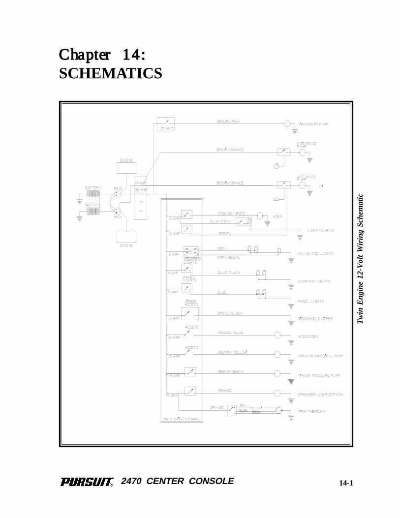
2470 CENTER CONSOLE
Chapter 14:Chapter 14:Chapter 14:Chapter 14:Chapter 14:
SCHEMATICS
Tw
in E
ngin
e 12
-Vol
t W
iring
Sch
emat
ic
14-1
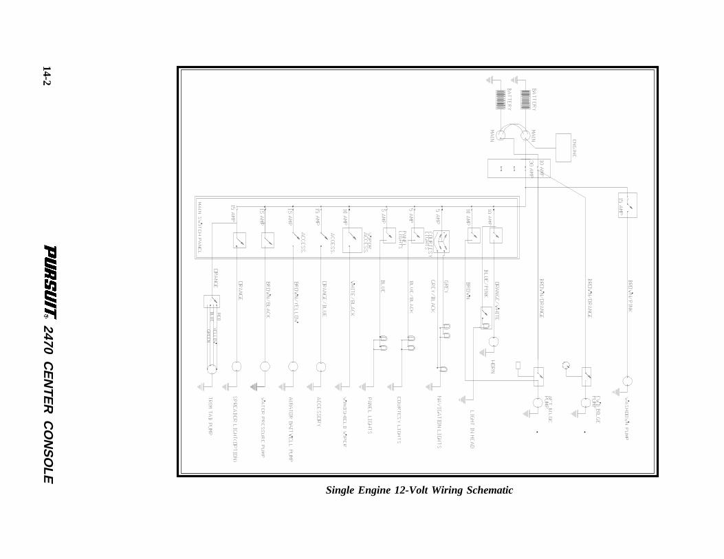
2470 CE
NTE
R C
ON
SO
LE
Single Engine 12-Volt Wiring Schematic
14-2
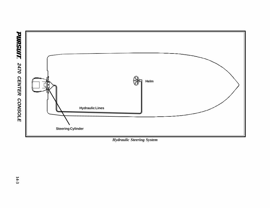
2470 CE
NTE
R C
ON
SO
LE
Hydraulic Steering System
Steering Cylinder
Helm
Hydraulic Lines
14-3
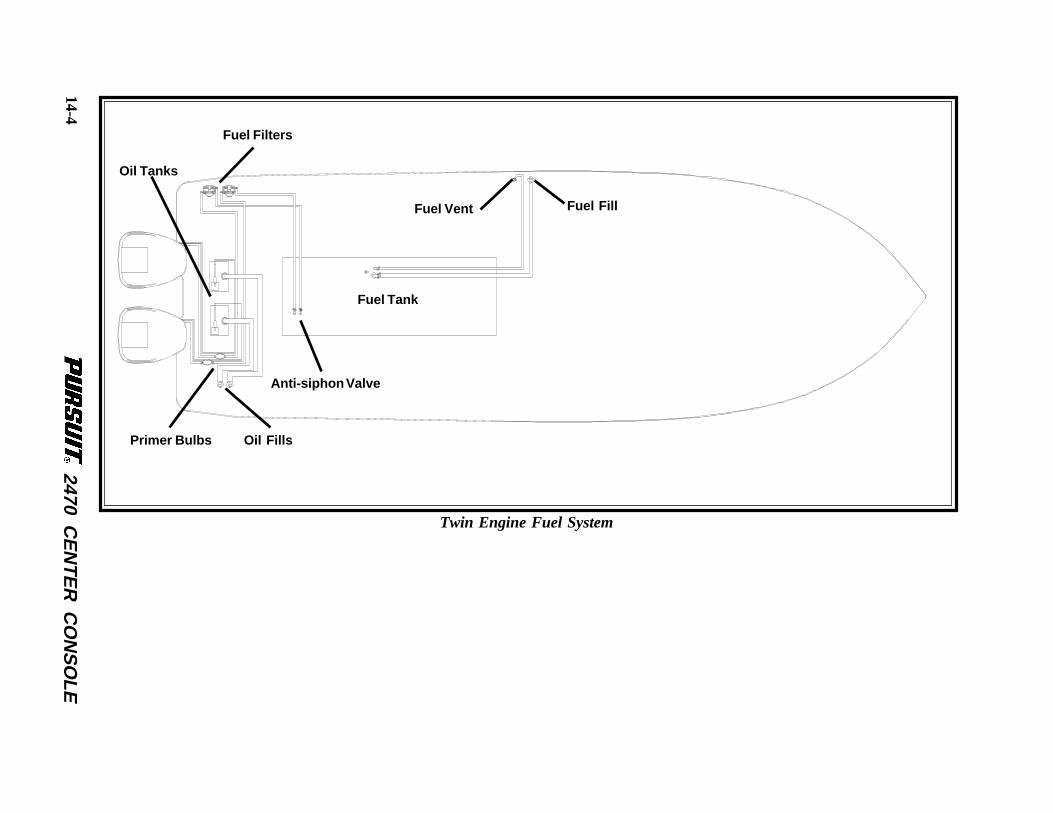
2470 CE
NTE
R C
ON
SO
LE
Twin Engine Fuel System
Fuel Vent Fuel Fill
Fuel Tank
Fuel Filters
Oil Tanks
Primer Bulbs Oil Fills
Anti-siphon Valve
14-4
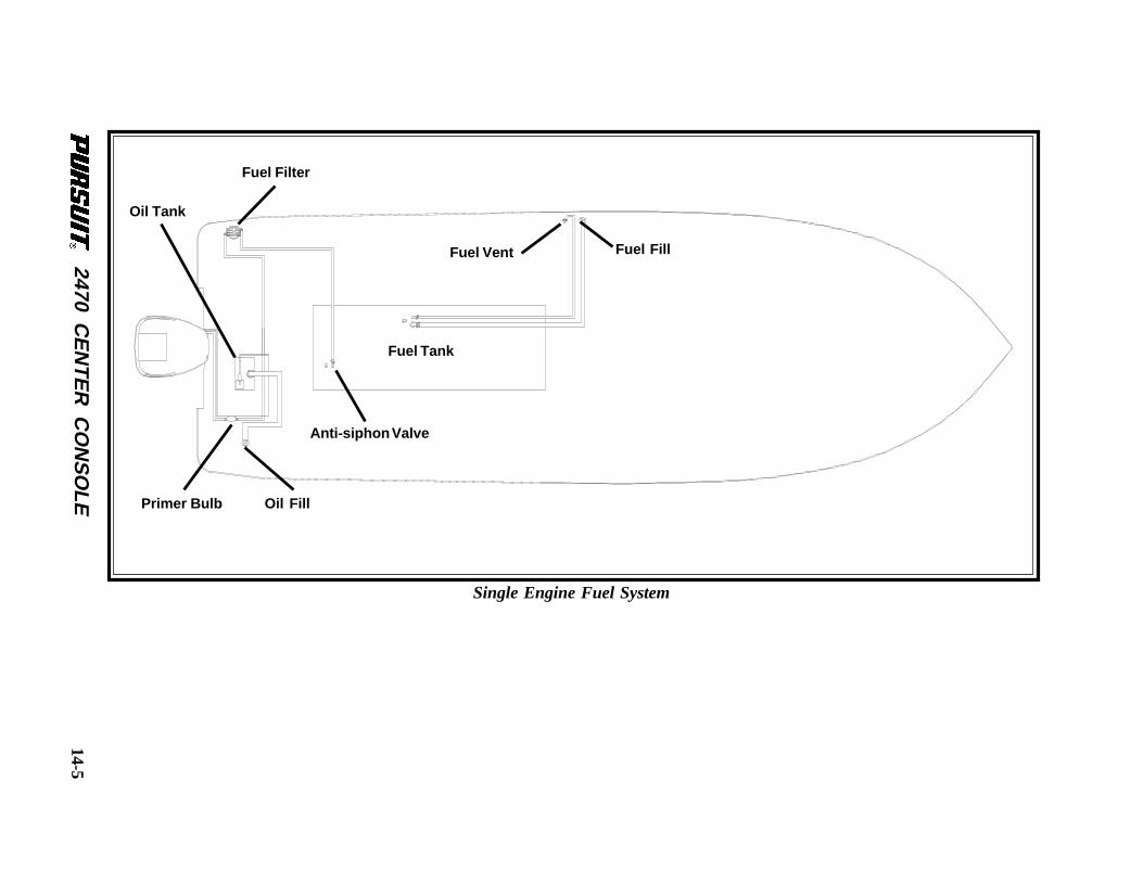
2470 CE
NTE
R C
ON
SO
LE
Single Engine Fuel System
Fuel Vent Fuel Fill
Fuel Tank
Fuel Filter
Oil Tank
Primer Bulb Oil Fill
Anti-siphon Valve
14-5
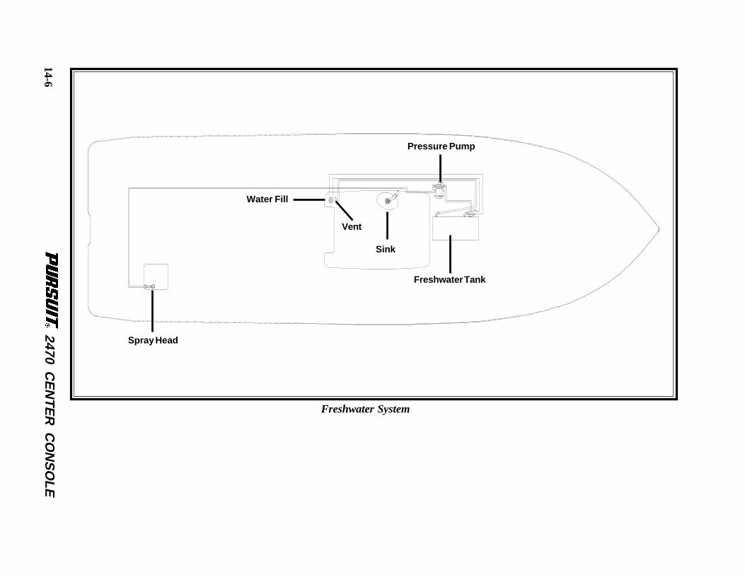
2470 CE
NTE
R C
ON
SO
LE
Freshwater System
Spray Head
Sink
Freshwater Tank
Vent
Water Fill
Pressure Pump
14-6
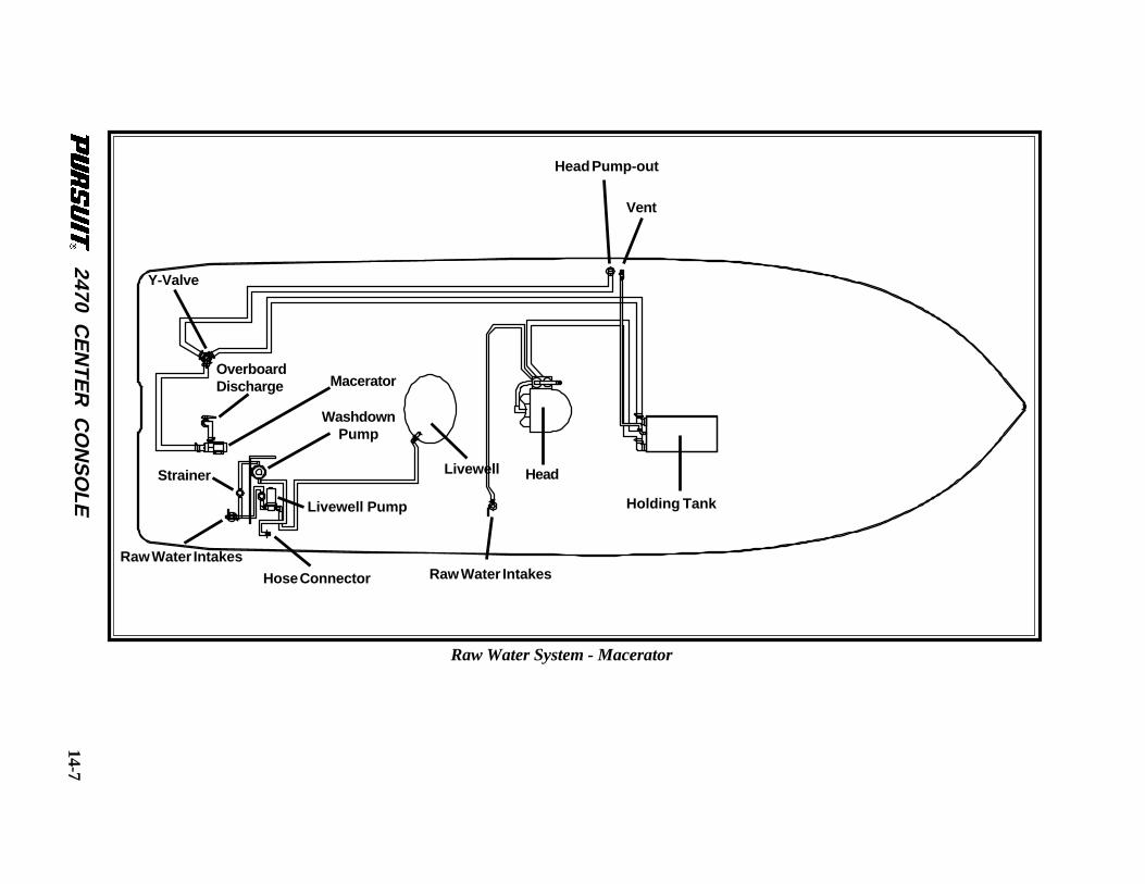
2470 CE
NTE
R C
ON
SO
LE
Raw Water System - Macerator
LivewellStrainer
Raw Water Intakes
Hose Connector
Head
Y-Valve
Raw Water Intakes
WashdownPump
Head Pump-out
Vent
Holding TankLivewell Pump
OverboardDischarge Macerator
14-7
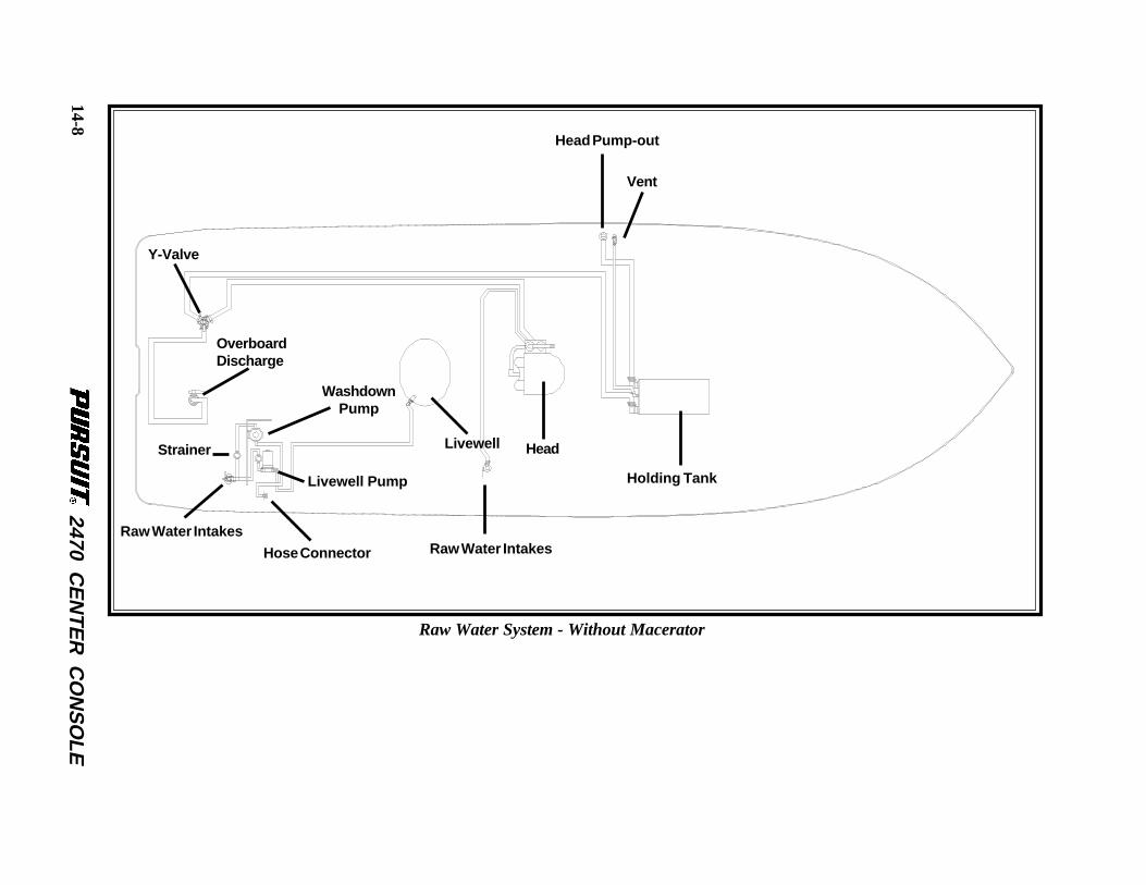
2470 CE
NTE
R C
ON
SO
LE
Raw Water System - Without Macerator
LivewellStrainer
Raw Water Intakes
Hose Connector
Head
Y-Valve
Raw Water Intakes
WashdownPump
Head Pump-out
Vent
Holding TankLivewell Pump
OverboardDischarge
14-8
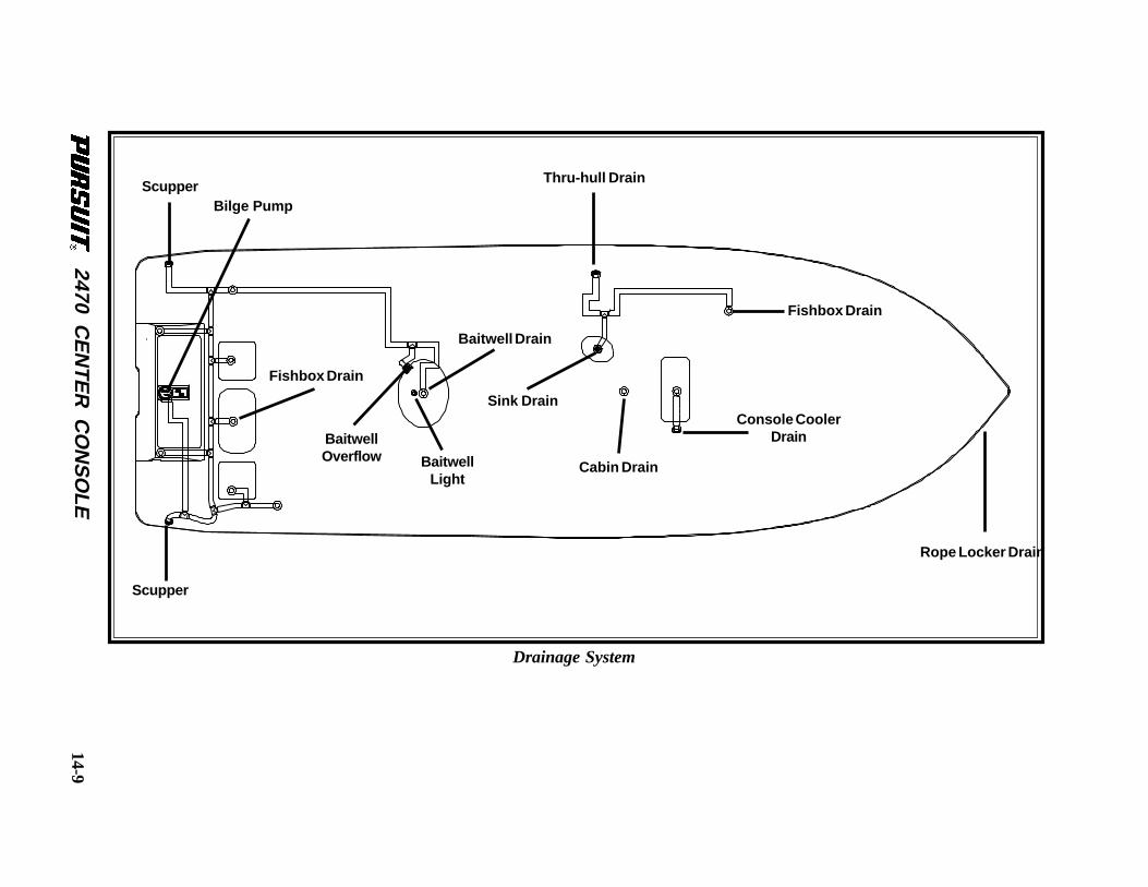
2470 CE
NTE
R C
ON
SO
LE
Drainage System
Rope Locker Drain
Baitwell Drain
Scupper
ScupperBilge Pump
Fishbox Drain
Sink Drain
Fishbox Drain
Cabin Drain
Console CoolerDrain
Thru-hull Drain
BaitwellOverflow Baitwell
Light
14-9

2470 CENTER CONSOLE
THIS PAGE WAS LEFT BLANKINTENTIONALLY
2470 CENTER CONSOLE
Appendix A:
GLOSSARY OF TERMS
Aft: In, near, or toward the stern of a boat.
Aground: A boat stuck on the bottom.
Amidships: In or toward the part of a boat midway between the bow and stern.
Anchor: A specially shaped heavy metal device designed to dig efficiently into the bottom undera body of water and hold a boat in place.
Anchorage: An area specifically designated by governmental authorities in which boats mayanchor.
Ashore: On shore.
Astern: Behind the boat, to move backwards.
Athwartship: At right angles to the center line of the boat.
Barnacles: Small, hard-shelled marine animals which are found in salt water attached to pilings,docks and bottoms of boats.
Beam: The breadth of a boat usually measured at its widest part.
Bearing: The direction of an object from the boat, either relative to the boat's direction or tocompass degrees.
Berth: A bunk or a bed on a boat.
Bilge: The bottom of the boat below the flooring.
Bilge Pump: A pump that removes water that collects in the bilge.
Boarding: Entering or climbing into a boat.
Boarding Ladder: Set of steps temporarily fitted over the side of a boat to assist persons comingaboard.
A-1
2470 CENTER CONSOLE
Boat Hook: Short shaft of wood or metal with a hook fitting at one end shaped to aid in extendingone’s reach from the side of the boat.
Bow: The front end of a boat's hull.
Bow Line: A line that leads forward from the bow of the boat.
Bow Rail: Knee high rails of solid tubing to aid in preventing people from falling overboard.
Bridge: The area from which a boat is steered and controlled.
Bridge Deck: A Deck forward and usually above the cockpit deck.
Broach: When the boat is sideways to the seas and in danger of capsizing, a very dangeroussituation that should be avoided.
Bulkhead: Vertical partition or wall separating compartments of a boat.
Cabin: Enclosed superstructure above the main deck level.
Capsize: When a boat lays on its side or turns over.
Chock: A deck fitting, usually of metal, with inward curving arms through which mooring oranchor lines are passed so as to lead them in the proper direction both on board and off the boat.
Cleat: A deck fitting, usually of metal with projecting arms used for securing anchor and mooringlines.
Closed Cooling System: A separate supply of freshwater that is used to cool the engine andcirculates only within the engine.
Coaming: A vertical piece around the edges of cockpit, hatches, etc. to stop water on deck fromrunning below.
Cockpit: An open space, usually in the aft deck, outside of the cabin.
Companionway: Opening in the deck of a boat to provide access below.
Compartment: The interior of a boat divided off by bulkheads.
Cradle: A framework designed to support a boat as she is hauled out or stored.
Cutlass Bearing: A rubber bearing in the strut that supports the propeller shaft.
A-2
2470 CENTER CONSOLE
Deck: The floor-like platform of a boat that covers the hull.
Displacement: The volume of water displaced by the hull. The displacement weight is the weightof this volume of water.
Draft: The depth of water a boat needs to float.
Dry Rot: A fungus attack on wood areas.
Dry-dock: A dock that can be pumped dry during boat construction or repair.
Electrical Ground: A connection between an electrical connector and the earth.
Engine Beds: Sturdy structural members running fore and aft on which the inboard engines aremounted.
EPIRB: Emergency Position Indicating Radio Beacon. Operates as a part of a worldwide satellitedistress system.
Even Keel: When a boat floats properly as designed.
Fathom: A measure of depth. One Fathom = 6 feet.
Fender: A soft object of rubber or plastic used to protect the topsides from scarring and rubbingagainst a dock or another vessel.
Fend off: To push or hold the boat off from the dock or another boat.
Flying Bridge: A control station above the level of the deck or cabin.
Flukes: The broad portions of an anchor which dig into the ground.
Fore: Applies to the forward portions of a boat near the bow.
Foundering: When a boat fills with water and sinks.
Freeboard: The height from the waterline to the lowest part of the deck.
Galley: The kitchen of a boat.
Grab Rail: Hand-hold fittings mounted on cabin tops or sides for personal safety when movingaround the boat, both on deck and below.
A-3
2470 CENTER CONSOLE
Ground Tackle: A general term including anchors, lines, and other gear used in anchoring.
Grounds: A boat touches the bottom.
Gunwale: The upper edge of a boat’s side.
Hand Rail: Rail mounted on the boat, for grabbing with your hand, to steady you while walkingabout the boat.
Harbor: An anchorage which provides reasonably good protection for a boat, with shelter fromwind and sea.
Hatch: An opening in the deck with a door or lid to allow for access down into a compartmentof a boat.
Head: A toilet on a boat.
Heat Exchanger: Used to transfer the heat that is picked up by the closed cooling system to theraw cooling water.
Helm: The steering and control area of a boat.
Hull: The part of the boat from the deck down.
I nboard: A boat with the engine mounted within the hull of the boat. Also refers to the centerof the boat away from the sides.
Inboard/outboard: Also stern drive or I/O. A boat with an inboard engine attached to an outboarddrive unit.
K eel: A plate or timber plate running lengthwise along the center of the bottom of a boat.
Knot: Unit of speed indicating nautical miles per hour. 1 knot = 1 nautical mile per hour (1.15miles per hour). A nautical mile is equal to one minute of latitude: 6076 feet. Knots times 1.15equals miles per hour. Miles per hour times .87 equals knots.
L ay-up: To decommission a boat for the winter (usually in northern climates).
Leeward: The direction toward which the wind is blowing.
A-4
2470 CENTER CONSOLE
Length On The Waterline (l.w.l.): A length measurement of a boat at the waterline from the sternto where the hull breaks the water near the bow.
Limber Hole: A passage cut into the lower edges of floors and frames next to the keel to allowbilge water to flow to the lowest point of the hull where it can be pumped overboard.
Line: The term used to describe a rope when it is on a boat.
Lists: A boat that inclines to port or starboard while afloat.
L.O.A.: Boat length overall.
Locker: A closet, chest or box aboard a boat.
Loran: An electronic navigational instrument which monitors the boat's position using signalsemitted from pairs of transmitting stations.
Lunch hook: A small light weight anchor typically used instead of the working anchor. Normallyused in calm waters with the boat attended.
M idships: The center of the boat.
Marina: A protected facility primarily for recreational small craft.
Marine Ways or Railways: Inclined planes at the water’s edge onto which boats are hauled.
Moored: A boat secured with cables, lines or anchors.
Mooring: An anchor permanently embedded in the bottom of a harbor that is used to secure a boat.
Nautical Mile: A unit of measure equal to one minute of latitude. (6076 feet)
Nun buoy: A red or red-striped buoy of conical shape.
Outboard: A boat designed for an engine to be mounted on the transom. Also a term that refersto objects away from the center line or beyond the hull sides of a boat.
Pad Eye: A deck fitting consisting of a metal eye permanently secured to the boat.
Pier: A structure which projects out from the shoreline.
Piles or Piling: A long column driven into the bottom to which a boat can be tied.
A-5
2470 CENTER CONSOLE
Pitching: The fore and aft rocking motion of a boat as the bow rises and falls.
Pitch: The measure of the angle of a propeller blade. Refers to the theoretical distance the boattravels with each revolution of the propeller.
P.F.D: Personal Flotation Device.
Port: The left side of the boat when facing the bow.
Porthole (port): The opening in the side of a boat to allow the admittance of light and air.
Propeller: A device having two or more blades that is attached to the engine and used forpropelling a boat.
Propeller Shaft: Shaft which runs from the back of the engine gear box, aft, through the stuffingbox, shaft log, struts, and onto which the propeller is attached.
Pyrotechnic Distress Signals: Distress signals that resemble the brilliant display of flares orfireworks.
Raw Water Cooled: Refers to an engine cooling system that draws sea water in through a hullfitting or engine drive unit, circulates the water in the engine, and then discharges it overboard.
Reduction Gear: Often combined with the reverse gear so that the propeller turns at a slower ratethan the engine.
Reverse Gear: Changes the direction of rotation of the propeller to provide thrust in the oppositedirection for stopping the boat or giving it sternway.
Roll: A boat’s sideways rotational motion in rough water.
Rope Locker: A locker, usually located in the bow of a boat, used for stowing the anchor line orchain.
Rubrail: Railing (often rubber or hard plastic) that runs along the boat’s sheer to protect the hullwhen coming alongside docks, piers, or other boats.
Rudder: A moveable flat surface that is attached vertically at or near the stern for steering.
Sea anchor: An anchor that does not touch the bottom. Provides drag to hold the bow in the mostfavorable position in heavy seas.
A-6
2470 CENTER CONSOLE
Scupper: An opening in the hull side or transom of the boat through which water on deck or inthe cockpit is drained overboard.
Seacock: Safety valves installed just inside the thru-hull fittings and ahead of the piping or hoserunning from the fittings.
Shaft Log: Pipe through which the propeller shaft passes.
Sheer: The uppermost edge of the hull.
Sling: A strap which will hold the boat securely while being lifted, lowered, or carried.
Slip: A boat's berth between two pilings or piers.
Sole: The deck of a cockpit or interior cabin.
Spring Line: A line that leads from the bow aft or from the stern forward to prevent the boat frommoving ahead or astern.
Starboard: The right side of a boat when facing the bow.
Steerageway: Sufficient speed to keep the boat responding to the rudder or drive unit.
Stem: The vertical portion of the hull at the bow.
Stern: The rear end of a boat.
Stow: To pack away neatly.
Stringer: Longitudinal members fastened inside the hull for additional structural strength.
Strut: Mounted to the hull which supports the propeller shaft in place.
Strut Bearing: See “cutlass bearing.”
Stuffing Box: Prevents water from entering at the point where the propeller shaft passes throughthe shaft log.
Superstructure: Something built above the main deck level.
Swamps: When a boat fills with water from over the side.
Swimming Ladder: Much the same as the boarding ladder except that it extends down into thewater.
A-7
2470 CENTER CONSOLE
Taffrail: Rail around the rear of the cockpit.
Thru-hull: A fitting used to pass fluids (usually water) through the hull surface, either above orbelow the waterline.
Topsides: The side skin of a boat between the waterline or chine and deck.
Transom: A flat stern at right angles to the keel.
Travel Lift: A machine used at boat yards to hoist boats out of and back into the water.
Trim: Refers to the boat's angle or the way it is balanced.
Trough: The area of water between the crests of waves and parallel to them.
Twin-Screw Craft: A boat with two propellers on two separate shafts.
Underway: When a boat moves through the water.
Wake: Disrupted water that a boat leaves astern as a result of its motion.
Wash: The flow of water that results from the action of the propeller or propellers.
Waterline: The plane of a boat where the surface of the water touches the hull when it is afloaton even keel.
Watertight Bulkhead: Bulkheads secured so tightly so as not to let water pass.
Wharf: A structure generally parallel to the shore.
Working Anchor: An anchor carried on a boat for most normal uses. Refers to the anchor usedin typical anchoring situations.
Windlass: A winch used to raise and lower the anchor.
Windward: Toward the direction from which the wind is coming.
Yacht Basin: A protected facility primarily for recreational small craft.
Yaw: When a boat runs off her course to either side.
A-8
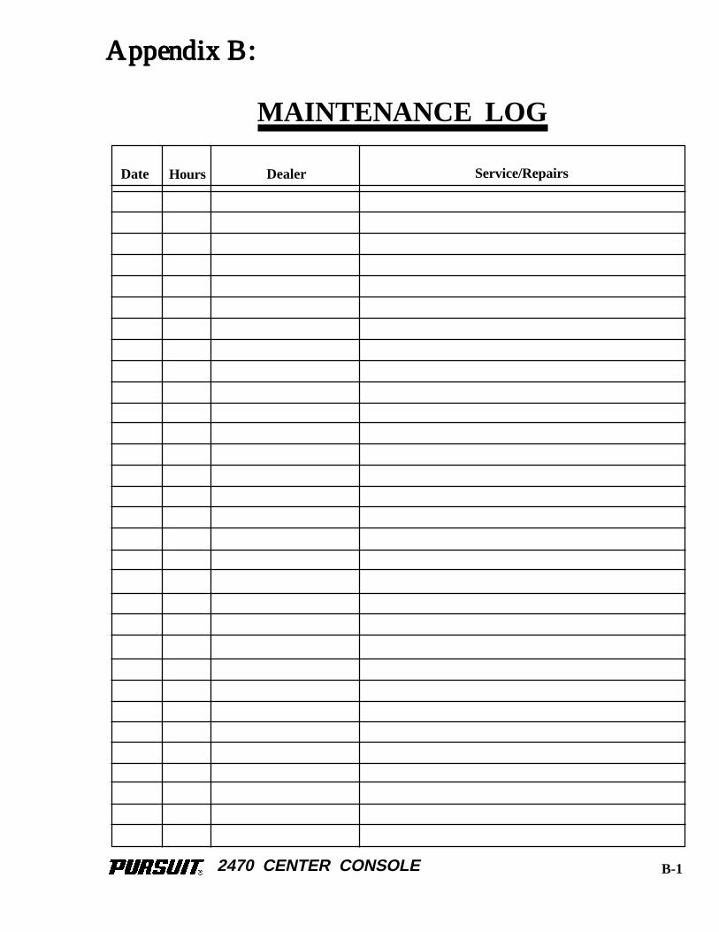
2470 CENTER CONSOLE
HoursDate Dealer Service/Repairs
MAINTENANCE LOG
Appendix B:Appendix B:Appendix B:Appendix B:Appendix B:
B-1

2470 CENTER CONSOLE
HoursDate Dealer Service/Repairs
MAINTENANCE LOG
B-2
2470 CENTER CONSOLE
HoursDate Dealer Service/Repairs
MAINTENANCE LOG
B-3

2470 CENTER CONSOLE
HoursDate Dealer Service/Repairs
MAINTENANCE LOG
B-4

2470 CENTER CONSOLE
HoursDate Dealer Service/Repairs
MAINTENANCE LOG
B-5
2470 CENTER CONSOLE
HoursDate Dealer Service/Repairs
MAINTENANCE LOG
B-6
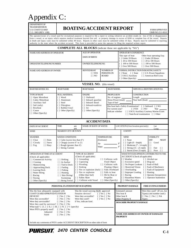
2470 CENTER CONSOLE
BOATING ACCIDENT REPORT FORM APPROVEDOMB NO.211-0010
DEPARTMENT OFTRANSPORTATIONU.S. COAST GUARDC.G. 1865 (REV. 1/88)
The operator/owner of a vessel used for recreational purposes is required to file a report in writing whenever an accident results in: loss of life or disappearancefrom a vessel, or an injury which requires medical treatment beyond first aid: or property damage in excess of $200 or complete loss of the vessel. Reportsin death and injury cases must be submitted within 48 hours. Reports in other cases must be submitted within 10 days. Reports must be submitted to reportingauthority in the state where the accident occurred. This form is provided to assist the operator in filing the required written report.
COMPLETE ALL BLOCKS (indicate those not applicable by “NA”)
OPERATOR TELEPHONE NUMBER
NAME AND ADDRESS OF OPERATOR
NAME AND ADDRESS OF OWNER
AGE OF OPERATOR
DATE OF BIRTH
OWNER TELEPHONE NO.
RENTED BOAT[ ] YES[ ] NO
NUMBER OFPERSONS ONBOARD
OPERATOR’S EXPERIENCEThis type of boat Other boat operating Exp.[ ] Under 20 Hours [ ] Under 20 Hours[ ] 20 to 100 Hours [ ] 20 to 100 Hours[ ] 100 to 500 Hours [ ] 100 to 500 Hours[ ] Over 500 Hours [ ] Over 500 Hours
FORMAL INSTRUCTION IN BOATING SAFETY[ ] None [ ] State [ ] U.S. Power Squadrons[ ] USCG Auxiliary [ ] American Red Cross[ ] Other (Specify)
VESSEL NO. (this vessel)
BOAT REGISTER. NO. BOAT NAME BOAT MAKE BOAT MODEL MFR HULL IDENTIFICATION NO.
TYPE OF BOAT[ ] Open Motorboat[ ] Cabin Motorboat[ ] Auxiliary Sail[ ] Sail (only)[ ] Rowboat[ ] Canoe[ ] Other (Specify)
HULL MATERIAL[ ] Wood[ ] Aluminum[ ] Steel[ ] Fiberglass[ ] Rubber/vinyl[ ] Other (Specify)
PROPULSIONNo. of enginesHorse Power (total)Type of fuel
CONSTRUCTIONLengthYear built (boat)
Has boat had a Safety Examination? [ ] Outboard [ ] NOFor current year? [ ] YES [ ] NO YearIndicate whether [ ] USCG Auxiliary Courtesy Marine Exam
[ ] State/local examination [ ] Other
ACCIDENT DATA
DATE OF ACCIDENT TIME ampm
NAME OF BODY OF WATER LOCATION (Give location precisely) LatLong
STATE NEAREST CITY OR TOWN COUNTY
WEATHER[ ] Clear [ ] Rain[ ] Cloudy [ ] Snow[ ] Fog [ ] Hazy
WATER CONDITIONS[ ] Calm (waves less than 6")[ ] Choppy (waves 6" to 2')[ ] Rough (greater than 6')[ ] Strong Current
TEMPERATURE(Estimate)
Air F°Water F°
WIND[ ] None[ ] Light (0 - 6mph)[ ] Moderate (7 - 14 mph)[ ] Strong (15 - 25 mph)[ ] Storm (Over 25 mph)
VISIBILITYDAY NIGHT[ ] Good[ ][ ] Fair [ ][ ] Poor [ ]
ENGINE[ ] Outboard[ ] Inboard gasoline[ ] Inboard diesel[ ] Inboard-outdrive[ ] Jet[ ] Other (Specify)
OPERATION AT TIME OF ACCIDENT(Check all applicable)[ ] Commercial Activity [ ] Drifting[ ] Cruising [ ] At Anchor[ ] Maneuvering [ ] Tied to Dock[ ] Approaching Dock [ ] Fueling[ ] Leaving Dock [ ] Fishing[ ] Water Skiing [ ] Hunting[ ] Racing [ ] Skin Diving/[ ] Towing Swimming[ ] Other (Specify) [ ] Being Towed
TYPE OF ACCIDENT(Check all applicable)[ ] Grounding [ ] Collision with[ ] Capsizing Fixed Object[ ] Flooding [ ] Collision with[ ] Sinking Floating Object[ ] Fire or explosion (fuel) [ ] Falls Overboard[ ] Fire or explosion [ ] Falls in boat
(Other than fuel) [ ] Hit by Boat or[ ] Fallen Skier Propeller[ ] Collision with Vessel [ ] Other (Specify)
WHAT IN YOUR OPINION CONTRIBUTED TO THEACCIDENT (Check all applicable)[ ] Weather [ ] Alcohol use[ ] Excessive speed [ ] Drug use[ ] No Proper Lookout [ ] Fault of Hull[ ] Restricted Vision [ ] Fault of Machinery[ ] Overloading [ ] Fault of Equipment[ ] Improper Loading [ ] Hunting[ ] Racing [ ] Operator Inexperience[ ] Hazardous Waters [ ] Operator Inattention[ ] Other (Specify)
PERSONAL FLOTATION DEVICES (PFDS) PROPERTY DAMAGE FIRE EXTINGUISHERS
Estimated amountThis boat $Other boat $Other Property $
Were they used? (If yes, listType(s) and number used.)[ ] Yes [ ] No [ ] NATypes:
DESCRIBE PROPERTY DAMAGE
NAME AND ADDRESS OF OWNER OF DAMAGEDPROPERTY
Was the boat adequately equipped withCOAST GUARD APPROVED FLOTATIONDEVICES? [ ] Yes [ ] NoWere they accessible? [ ] Yes [ ] NoWere they serviceable? [ ] Yes [ ] NoWere they used by survivors? [ ] Yes [ ] NoWhat type? [ ] I, [ ] II, [ ] III, [ ] IV, [ ] V (specify)Were PFD’s properly used? [ ] Yes [ ] No
Adjusted [ ] Yes [ ] NoSized [ ] Yes [ ] No
Include any comments of PFD’s under ACCIDENT DESCRIPTION on other side of form
Was the vessel carrying NON approvedflotation devices? [ ] Yes [ ] NoWere they accessible? [ ] Yes [ ] NoWere they used? [ ] Yes [ ] NoIf Yes, indicate kind.
Appendix C:
C-1
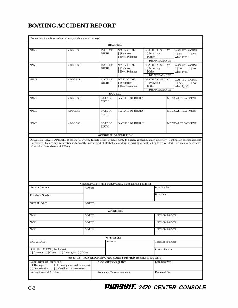
2470 CENTER CONSOLE
If more than 3 fatalities and/or injuries, attach additional form(s)
WAS VICTIM?[ ] Swimmer[ ] Non Swimmer
DATE OFBIRTH
ADDRESSNAME DEATH CAUSED BY[ ] Drowning[ ] Other
[ ] DISAPPEARANCE
WAS PFD WORN?[ ] Yes [ ] NoWhat Type?
WAS VICTIM?[ ] Swimmer[ ] Non Swimmer
DATE OFBIRTH
ADDRESSNAME DEATH CAUSED BY[ ] Drowning[ ] Other
WAS PFD WORN?[ ] Yes [ ] NoWhat Type?
WAS VICTIM?[ ] Swimmer[ ] Non Swimmer
DATE OFBIRTH
ADDRESSNAME DEATH CAUSED BY[ ] Drowning[ ] Other
WAS PFD WORN?[ ] Yes [ ] NoWhat Type?
[ ] DISAPPEARANCE
[ ] DISAPPEARANCE
ADDRESSNAME
ADDRESSNAME
ADDRESSNAME
NATURE OF INJURYDATE OFBIRTH
DATE OFBIRTH
DATE OFBIRTH
NATURE OF INJURY
NATURE OF INJURY
MEDICAL TREATMENT
MEDICAL TREATMENT
MEDICAL TREATMENT
DESCRIBE WHAT HAPPENED (Sequence of events. Include Failure of Equipment. If diagram is needed, attach separately. Continue on additional sheetsif necessary. Include any information regarding the involvement of alcohol and/or drugs in causing or contributing to the accident. Include any descriptiveinformation about the use of PFD's.)
INJURED
VESSEL NO. 2 (if more than 2 vessels, attach additional form (s)
DECEASED
ACCIDENT DESCRIPTION
Name of Owner
Telephone Number
Name of Operator Address
Address
AddressName
Name
Name
Address
Address
Boat Name
Boat Number
Telephone Number
Telephone Number
Telephone Number
Telephone Number
Date Submitted
Date Received
Reviewed By
AddressSIGNATURE
QUALIFICATION (Check One)[ ] Operator [ ] Owner [ ] Investigator [ ] Other
Causes based on (check one)[ ] This report [ ] Investigation and this report[ ] Investigation [ ] Could not be determinedPrimary Cause of Accident Secondary Cause of Accident
Name of Reviewing Office
(do not use) - FOR REPORTING AUTHORITY REVIEW (use agency date stamp)
WITNESSES
WITNESSES
BOATING ACCIDENT REPORT
C-2