Embed Size (px)
Citation preview

XJRR 8/26/13 per e-mail with J. Gunter
Best Available Copy
Aug 26, 2013DATE:
By Julia Raymer at 9:16 am, Aug 26, 2013
87
8/26/13

Rev. 0 08/26/2013
E-mail approval - Page 3 of 3
By Julia Raymer at 9:18 am, Aug 26, 2013
3JRR 8/26/13

By Julia Raymer at 9:18 am, Aug 26, 2013
Approved for Public Release; Further Dissemination Unlimited
08/26/2013
3JRR 8/26/13
1
Gunter, Jason R
From: Lawrence, Hugh KSent: Monday, August 12, 2013 5:19 PMTo: Gunter, Jason RCc: Kunz, Ashley C; Wolfley, Clinton TSubject: RE: RPP-RPT-54817 For Safety Review
Jason, I have reviewed the photos in the provided document (RPP‐RPT‐54817‐ 241‐AY 101 Tank Construction Extent of Condition Review for Tank Integrity) from an Industrial Safety viewpoint, as requested. Based on this review the photos
in this document are approved for use. Any question or comment please ask. Hugh Lawrence WRPS Safety Programs cell (208) 547‐7334
From: Gunter, Jason R Sent: Monday, August 12, 2013 4:51 PM To: Lawrence, Hugh K Cc: Barnes, Travis J; Venetz, Theodore J; Boomer, Kayle D; Washenfelder, Dennis J Subject: RPP-RPT-54817 For Safety Review Hugh, Could you please provide safety review of the pictures in RPP‐RPT‐54817? It is available at the following link: http://idmsweb.rl.gov/idms/livelink.exe?func=ll&objId=178035382&objAction=browse&viewType=1 If acceptable, please email your approval to me. Thanks!
Jason R. Gunter
Mechanical Engineer Tank and Pipeline Integrity Desk Location: 2750E‐D‐154F‐3 Office: 509‐376‐0904 Cell: 509‐713‐3071 Email: [email protected]
Page 3 of 3

RPP-RPT-54817, Rev. 0
241-AY-101 Tank Construction Extent of Condition Review for Tank Integrity
T.J. Barnes and J.R. Gunter Washington River Protection Solutions, LLC Richland, WA 99352 U.S. Department of Energy Contract DE-AC27-08RV14800 EDT/ECN: DRF UC: Cost Center: 2KE00 Charge Code: 201611 B&R Code: N/A Total Pages: Key Words: DST, 241-AY Tank Farm, AY-101, leak, tank construction, extent of condition
Abstract: This report provides the results of an extent of condition construction history review for tank 241-AY-101. The construction history of tank 241-AY-101 has been reviewed to identify issues similar to those experienced during tank AY-102 construction. Those issues and others impacting integrity are discussed based on information found in available construction records, using tank AY-102 as the comparison benchmark. In tank 241-AY-101, the second double-shell tank constructed, similar issues as those with tank 241-AY-102 construction reoccurred. The overall extent of similary and affect on tank 241-AY-101 integrity is described herein.
TRADEMARK DISCLAIMER. Reference herein to any specific commercial product, process, or service by trade name, trademark, manufacturer, or otherwise, does not necessarily constitute or imply its endorsement, recommendation, or favoring by the United States Government or any agency thereof or its contractors or subcontractors.
Release Approval Date Release Stamp
Approved For Public Release
A-6002-767 (REV 3)
87
By Julia Raymer at 9:22 am, Aug 26, 2013
Aug 26, 2013DATE:
RPP-RPT-54817 Revision 0
241-AY-101 Tank Construction Extent of Condition Review for Tank Integrity
T. J. Barnes J. R. Gunter
Washington River Protection Solutions, LLC
Date Published August 2013
Prepared for the U.S. Department of Energy Office of River Protection
Contract No. DE-AC27-08RV14800

RPP-RPT-54817, Rev. 0
EXECUTIVE SUMMARY
The construction history of the 241-AY-101 (AY-101) tank has been reviewed to identify any concerns for the long-term integrity of the tank. This initial review was prompted by construction issues identified during the formal leak assessment for tank 241-AY-102 (AY-102), RPP-ASMT-53793, Tank 241-AY-102 Leak Assessment Report. In tank AY-102, bulges in the secondary liner, deterioration of refractory during post-weld stress relieving (post-weld heat treatment), and primary tank floor plate welding rework during construction left residual stresses in the tank that may have accelerated corrosion and contributed to the primary tank failure. The main purpose of this review was to determine whether construction modifications made between tanks AY-102 and AY-101 either improved the integrity of tank AY-101 or produced similar reduced margins. During construction of the 241-AY tank farm, the most significant deficiency found in the review was the degradation and repair of the refractory in tanks AY-101 and AY-102. Both refractories were exposed to similar conditions of moisture and freezing temperatures during the curing stage, which is believed to have contributed to the friable nature and reduced vertical compressive strength. The refractory repairs required the outer 21 in. of the periphery refractory to be chipped out all the way around the tank and replaced with reinforced structural concrete. Significant problems arose with welding of the secondary liner and primary tank bottoms of tank AY-102 with a weld rejection rate of 33.8%. Welding improved with fabrication of tank AY-101 with a weld rejection of 10.2%. Regarding tank bottom flatness, tank AY-101 had a total of six instances of secondary liner bottom bulging as compared to tank AY-102 with 22 instances. No QA inspections indicated that bulging of the primary tank bottom occurred in tank AY-101 and the information discovered substantiates that it met specification. Despite this documentation, photos from refractory repair after stress relief indicate that voids existed between the primary tank and refractory surface. These voids could be attributed to primary tank bottom bulges, which would indicate unsupported areas of the primary tank exist in tank AY-101. This lack of support was identified a contributing factor to primary tank failure in tank AY-102. The post-weld stress relieving of tank AY-101 was more successful when compared to tank AY-102. Tank AY-101 was stress relieved at 1000°F for 4 hours, which did not meet the specification of 1100°F ± 50°F for 1 hour. This reduced temperature, longer duration, stress relief method was deemed to be an acceptable alternative per provisions of the ASME Boiler and Pressure Vessel Code, which indicated that it would still produce a suitable stress relief and resistance to stress corrosion cracking. Although some improvement was seen in the construction of tank AY-101 following tank AY-102, many of the same issues found in tank AY-102 also exist in tank AY-101 and it should therefore remain in a category subject to enhanced inspection.
i

RPP-RPT-54817, Rev. 0
TABLE OF CONTENTS
1.0 Introduction ......................................................................................................................... 1-1
1.1 Purpose .......................................................................................................................... 1-1
1.2 Overview ....................................................................................................................... 1-1
1.3 Double-Shell Tank Description .................................................................................... 1-2
2.0 241-AY Farm Construction Information ............................................................................ 2-1
3.0 Materials of Construction ................................................................................................... 3-1
3.1 Concrete ........................................................................................................................ 3-1
3.2 Reinforcing Bar ............................................................................................................. 3-1
3.3 Steel Plate...................................................................................................................... 3-1
Secondary Plate ....................................................................................................... 3-1 3.3.1 Primary Plate ........................................................................................................... 3-1 3.3.2 Material Certification .............................................................................................. 3-2 3.3.3
3.4 Refractory ..................................................................................................................... 3-3
3.5 Piping ............................................................................................................................ 3-3
4.0 Construction Sequence........................................................................................................ 4-1
4.1 Concrete Foundation ..................................................................................................... 4-2
4.2 Secondary Liner Bottom ............................................................................................... 4-2
4.3 Refractory ..................................................................................................................... 4-3
4.4 Secondary Liner Wall and Concrete Shell .................................................................... 4-5
4.5 Primary Tank Bottom ................................................................................................... 4-5
4.6 Primary Tank Wall and Tank Dome ............................................................................. 4-6
4.7 Primary Tank Stress Relieving ..................................................................................... 4-7
4.8 Primary Tank Hydrostatic Test ................................................................................... 4-10
4.9 Complete Secondary Liner and Tank Penetrations ..................................................... 4-10
4.10 Concrete Dome Pour ................................................................................................... 4-11
4.11 Tank Appurtenances ................................................................................................... 4-12
5.0 Construction Issues ............................................................................................................. 5-1
5.1 Weld Rejection and Non-Destructive Examination ...................................................... 5-1
5.2 Refractory ..................................................................................................................... 5-3
Material Selection ................................................................................................... 5-3 5.2.1 Refractory Thickness Variation .............................................................................. 5-4 5.2.2 Evaluation of Refractory After Tank Hydrostatic Test ........................................... 5-7 5.2.3 Sampling ............................................................................................................... 5-11 5.2.4
ii

RPP-RPT-54817, Rev. 0
Waste Compatibility ............................................................................................. 5-16 5.2.55.3 Stress Relieving of the Primary Tank ......................................................................... 5-22
5.4 Tank Bottom Flatness ................................................................................................. 5-24
Secondary Liner Bottom Flatness ......................................................................... 5-24 5.4.1 Primary Tank Bottom Flatness ............................................................................. 5-25 5.4.2 Tank AY-101 Bottom Flatness Issues Summary .................................................. 5-25 5.4.3
6.0 Conclusions ......................................................................................................................... 6-1
7.0 References ........................................................................................................................... 7-1
TABLE OF APPENDICES
241-AY-101 Tank Log Book Key Event Table ................................................ A-1 Appendix A 241-AY-101 Weld Maps ................................................................................... B-1 Appendix B Tank Deficiency Documentation ....................................................................... C-1 Appendix C
LIST OF FIGURES
Figure 1-1. Double-Shell Tank Design ........................................................................................ 1-2
Figure 3-1. Primary Tank Wall Configuration and Thickness .................................................... 3-2
Figure 4-1. Laying Reinforcing Steel for Foundations (Photo No. 8000) (Taken 9/25/1968) .................................................................................................................................... 4-2
Figure 4-2. Foundations for Tank AY-101 (background) and Tank AY-102 (Photo No. 8041) (Taken 11/22/1968) ........................................................................................................... 4-2
Figure 4-3. Radial Welded Section of Secondary Bottom, Tank AY-101 (Photo No. 8049) (Taken 12/26/1968) ........................................................................................................... 4-2
Figure 4-4. Beam Supports in Tank AY-102 for Raising and Lowering the Tank Bottom ........ 4-3
Figure 4-5. Diagram of Ventilation Flow Path ............................................................................ 4-3
Figure 4-6. Completed Refractory in Tank AY-101 (Photo No. 8124) (Taken 3/27/1969) ........ 4-4
Figure 4-7. Tank AY-102 (foreground) Secondary Liner Wall Fabrication and Concrete Forms (Photo No. 8131) (Taken 3/27/1969)................................................................................ 4-5
Figure 4-8. Tank AY-101 Completed Primary Bottom and Welding of the First Course Primary Wall (Photo No. 8179) (Taken 6/23/69) ........................................................................ 4-6
Figure 4-9. Tank AY-102 Primary Dome Construction (Photo No. 50449-1) (Taken 8/19/1969) .................................................................................................................................... 4-6
Figure 4-10. Installing Insulation in the Annulus of Tank AY-102 in Preparation of Stress Relieving (Photo No. 50618-3) (Taken 9/12/1969) ..................................................................... 4-7
iii

RPP-RPT-54817, Rev. 0
Figure 4-11. Configuration of Stress Relief Equipment in Tank AY-101 ................................... 4-8
Figure 4-12. Water is Pumped Out of Tank AY-102 (foreground) After Hydrostatic Test While Crews Are Preparing Tank AY-101 for Stress Relieving (Photo No. 50906-13) (Taken 10/24/1969) .................................................................................................................... 4-10
Figure 4-13. Fabricator Installing Rebar (Photo No. 51084-1) (Taken 11/17/1969)................. 4-11
Figure 4-14. Rebar Installation for Concrete Dome Pour (Photo No. 51084-2) (Taken 11/17/1969) ................................................................................................................................ 4-11
Figure 4-15. Center of Dome and Completed Internals of Tank AY-102 (Photo No. 51660-18) (Taken 2/20/1970) .................................................................................................... 4-12
Figure 4-16. Concrete Dome Complete, Looking Southwest (Photo No. 51305-13) (Taken 12/22/1969) .................................................................................................................... 4-12
Figure 5-1. Primary Tank Bottom Cleats Engaged in Container Ring ........................................ 5-5
Figure 5-2. Primary Tank Bottom Cleat Design Change Summary ............................................ 5-6
Figure 5-3. Tank AY-101 Refractory Repair ............................................................................... 5-8
Figure 5-4. Tank AY-101 Refractory Repair (Photo No. 52720-3) (Taken 7/23/1970).............. 5-8
Figure 5-5. Tank AY-101 Refractory Repair (Photo No. 52788-8) (Taken 8/3/1970)................ 5-8
Figure 5-6. Tank Configuration with Three-Inch Secondary Liner Bottom Curvature During Hydrostatic Test ............................................................................................................. 5-10
Figure 5-7. Tank AY-102 Finish Perimeter Concrete Support Ring ......................................... 5-11
Figure 5-8. Damaged Refractory in AY Farm after removal of 21 in. of periphery, still showing friable top layer (Photo 52788-8) ................................................................................ 5-19
Figure 5-9. Adsorption of 137Cs on Freshly Prepared Metal Hydroxides (left) and on the Metal Hydroxides after Ten Days of Aging (right) as a Function of the pH of the Solution. ..................................................................................................................................... 5-21
Figure 5-10. Example of Warped Secondary Liner Bottom Knuckle (Photo – 8074) .............. 5-25
LIST OF APPENDIX FIGURES
App Figure B-1. Tank AY-101 Primary Tank Bottom Weld Map ............................................. B-2
App Figure B-2. Tank AY-101 Secondary Bottom Weld Map .................................................. B-3
App Figure B-3. Tank AY-101 Primary Shell Weld Map .......................................................... B-4
App Figure B-4. Tank AY-101 Secondary Shell Weld Map ...................................................... B-5
App Figure C-1. Memo from G. Kligfield (Dated 11/5/1969) ................................................... C-2
App Figure C-2. Kaolite Change Request Letter (Dated 9/4/1968) ........................................... C-3
App Figure C-3. Kaolite Record of Design Change (Dated 10/2/1968)..................................... C-4
iv

RPP-RPT-54817, Rev. 0
App Figure C-4. Project Status (Dated 7/12/1970) ..................................................................... C-5
App Figure C-5. Project Status (Dated 7/26/1970) ..................................................................... C-6
App Figure C-6. Vitro-HES Quality Assurance Checklist Primary Tank Bottom Condition (Dated 7/10/1969) ...................................................................................................... C-7
LIST OF TABLES
Table 1-1. Double-Shell Construction and Age as of 2013 ......................................................... 1-2
Table 4-1. Post-Weld Stress Relieving in 241-AY Tank Farm ................................................... 4-9
Table 5-1. 241-AY Tank Farm Primary Tank Bottom Weld Comparison .................................. 5-1
Table 5-2. 241-AY Tank Farm Non-Destructive Examinations Used During Construction ...... 5-3
Table 5-3. Kaolite Laboratory Test Results After Freezing Samples at 10°F ........................... 5-12
Table 5-4. Tank AY-101 Refractory Installation and Weather Event Details ........................... 5-13
Table 5-5. Comparison of Properties for Kaolite 2000 and Kaolite 2200-LI ............................ 5-17
Table 5-6. Synthetic Waste Solution Tested on Kaolite 20 and Kaolite 2200-LI ..................... 5-18
Table 5-7. Analysis of Damaged Refractory from Tanks AY-102 and AY-101 ....................... 5-20
Table 6-1. Summary Comparison of Tank AY-101 Construction to Tank AY-102 ................... 6-2
v

RPP-RPT-54817, Rev. 0
LIST OF TERMS
Abbreviations and Acronyms
AEC Atomic Energy Commission ARCHO Atlantic Richfield Hanford Company ASME™ American Society of Mechanical Engineers ASTM™ American Society for Testing and Materials DST Double-Shell Tank EFCOG Energy Facilities Contractors Group EOC Extent of Condition HES Hanford Engineering Services IDMS Integrated Data Management System LDP Leak Detection Pit PDM Pittsburgh-Des Moines Steel Company PWHT Post Weld Heat Treatment (also referred to as
post-weld stress relieving and annealing) QA Quality Assurance RHA Records Holding Area WRPS Washington River Protection Solutions LLC WST Waste Storage Tank WTP Waste Treatment and Immobilization Plant
Units
ft Feet in Inch h Hour lb Pound gal Gallon
TRADEMARK DISCLOSURE
ASME is a registered trademark of American Society of Mechanical Engineers ASTM is a registered trademark of American Society for Testing and Materials Kaolite is a registered trademark of Babcock & Wilcox Company
vi
RPP-RPT-54817, Rev. 0
1.0 INTRODUCTION
This document provides an overview of the construction history of tank AY-101, noting any difficulties encountered. On November 7, 2012, it was determined that the primary tank of double-shell tank (DST) AY-102 was leaking (RPP-ASMT-53793, Rev. 0 Tank 241-AY-102 Leak Assessment Report). In tank AY-102, bulges in the secondary liner, deterioration of refractory during post-weld stress relieving (post-weld heat treatment), and primary tank floor plate welding rework during construction left residual stresses in the tank that may have accelerated corrosion and contributed to the primary tank failure. Following identification of the tank AY-102 probable leak cause, an Extent of Condition evaluation was prepared using U.S. Department of Energy’s Energy Facilities Contractors Group (EFCOG) Guidance for Extent of Conditions Evaluations. The EFCOG process was used to identify other DSTs with construction, waste storage, or thermal histories similar to that of tank AY-102 (WRPS-1204931, Double-Shell Tank 241-AY-102 Primary Tank Leak Extent of Condition Evaluation and Recommended Annulus Visual Inspection Intervals). The EOC evaluation identified six tanks with similar construction for additional evaluation which include: 241-AY-101, 241-AZ-101, 241-AZ-102, 241-SY-101, 241-SY-102 and 241-SY-103. One of the evaluations was to identify any similarities in construction that could be a precursor for accelerated corrosion and premature failure.
1.1 PURPOSE
The construction history of tank AY-101 has been reviewed to identify issues similar to those experienced during tank AY-102 construction. In this document, those issues and others impacting integrity are discussed based on information found in available construction records, using tank AY-102 as the comparison benchmark.
1.2 OVERVIEW
Six double shell tank (DST) farms were constructed over a period of roughly 18 years (from 1968 to 1986), with a presumed design life of 20 to 50 years. Tank AY-101 was the second tank to be constructed in the 241-AY tank farm and is the focus of this report. Table 1-1 provides the construction dates, year of initial service, and the expected service life for the DSTs.
1-1

RPP-RPT-54817, Rev. 0
Table 1-1. Double-Shell Construction and Age as of 2013
1.3 DOUBLE-SHELL TANK DESCRIPTION
Each DST consists of a primary carbon steel tank, 75 ft. in diameter, inside of a secondary carbon steel liner, which is surrounded by a reinforced-concrete shell. Both the primary tank and secondary liner are constructed in four courses. The primary steel tank rests atop an 8 in. insulating concrete slab, separating it from the secondary steel liner, and providing for air circulation/leak detection channels under the primary tank bottom plate. An annular space of 2.5 ft. exists in between the secondary liner and primary tank, allowing for visual examination of the tank wall and secondary liner annular surfaces and ultrasonic volumetric inspections of the primary tank walls and secondary liners, as well as other activities.
Figure 1-1. Double-Shell Tank Design
Tank AY-101 has 126 risers penetrating the dome, providing access for video cameras, ultrasonic inspection devices, waste sampling devices, mixer pumps, and other equipment requiring access to either the primary tank interior or annular space. Drawing H-14-010506, Sheets 2, Dome Penetration Schedules (WST/WSTA) Tank 241-AY-101, provides a complete depiction of these tank penetrations. Above tank AY-101, there are six pits extending from grade to varying depths, which house valves and pumps.
Tank Farm
Number of Tanks
Construction Period
Construction Project
Initial Operation
Service Life
Current Age
241-AY 2 1968 – 1970 IAP-614 1971 40 42
241-AZ 2 1970 – 1974 HAP-647 1976 20 37
241-SY 3 1974 – 1976 B-101 1977 50 36
241-AW 6 1976 – 1979 B-120 1980 50 33
241-AN 7 1977 – 1980 B-130, B-170 1981 50 32
241-AP 8 1982 – 1986 B-340 1986 50 27
Total 28
1-2

RPP-RPT-54817, Rev. 0
2.0 241-AY FARM CONSTRUCTION INFORMATION
The 241-AY tank farm, the first double-shell tank farm, was constructed between 1968 and 1970. It was designated as Project IAP-614, Purex Tank Farm Expansion. The Atlantic Richfield Hanford Company (ARHCO) built the tank farm for the Atomic Energy Commission (AEC). The 241-AY tank farm contained two tanks and ancillary equipment. The Pittsburgh-Des Moines Steel Company (PDM) was contracted to build the farm. Construction management was provided by Vitro Engineering. The 241-AY tank farm was built according to ARH-205, Design Criteria Purex AY Tank Farm, and the following specifications:
• HWS-7789, Specification for Primary and Secondary Steel Tanks Purex Tank Farm Expansion
• HWS-7790, Specification for Excavation and Tank Foundations Purex Tank Farm Expansion Building 241-AY Project IAP-614
• HWS-7791, Specification for Side Walls and Dome Nuclear Waste Storage Tank Project IAP-614 Purex Tank Farm Expansion
• HWS-7792, Specification for Completion of 241-AY Purex Tank Farm Expansion Project IAP-614
To obtain information about the construction history of tank AY-101, the Record Holding Area (RHA) and Integrated Data Management System (IDMS) were queried for boxes containing files from Project IAP-614. This information includes:
1. Weld radiography 2. Materials Certifications 3. Quality Assurance construction log books 4. Project reports and correspondence
The following sections provide an aggregation of the information collected, highlighting important events and information relevant to leak integrity. From the information collected, the resulting quality of construction and any issues or difficulties noted are discussed in this document.
2-1

RPP-RPT-54817, Rev. 0
3.0 MATERIALS OF CONSTRUCTION
3.1 CONCRETE
All concrete used in the concrete vertical wall and dome required a 3,000 psi, 28-day compressive strength. The concrete samples were taken and tested at 28 days to confirm the compressive strength. The cement for structural concrete conformed to Federal Specification SS-C-192g, utilizing Type V for tank walls and Type III for the haunch and dome (HWS-7791). From the American Society for Testing and Materials (ASTM™)1 C150, Standard Specification for Portland Cement, Type III cement is high early strength cement and Type V is high sulfate resistant cement.
3.2 REINFORCING BAR
The reinforcing bar was manufactured to American Society for Testing and Materials (ASTM) A15, specifications with minimum yield strength of 40,000 psi. The tank foundation was reinforced with #5, #6, and #7 rebar (see H-2-64306, Tank Foundation Plan, for details). The concrete walls and dome sections were reinforced with #4, #6, #8, and #9 rebar (see H-2-64310, Concrete Tank Section and Details, for details).
3.3 STEEL PLATE
All sheet steel used in the 241-AY tank farm primary tank and secondary liner construction was manufactured to ASTM A515-65, Carbon Steel of Intermediate Tensile Strength for Fusion-Welded Boilers and Other Pressure Vessels for Intermediate and Higher Temperature Service, Grade 60, standards. The tanks were erected using the 1965 Edition of the ASME2 Boiler and Pressure Vessel Code.
Secondary Plate 3.3.1
The secondary liner consisted of 1/4 in. thick plates. Drawing H-2-64449, Tank Elevation and Details, sheets 1 and 2, show these details.
Primary Plate 3.3.2
The primary tank bottom primarily consists of 3/8 in. carbon steel plates, except the 4 ft. diameter center which is composed of a 1 in. thick carbon steel plate, and a 7/8 in. carbon steel plate is used for the primary tank bottom knuckle. The primary tank wall varies from 7/8 in. thick carbon steel at the bottom knuckle to 3/8 in. thick at the top transition plate. The first course is 3/4 in. thick and the next two courses are 1/2 in. thick.
1 ASTM is a registered trademark of American Society for Testing and Materials 2 ASME is a registered trademark of American Society of Mechanical Engineers
3-1

RPP-RPT-54817, Rev. 0
The top transition plate is welded to a 3/8 in. thick top knuckle. The top knuckle is then welded to the primary tank dome, which is constructed of 3/8 in. thick plates (see H-2-64449, sheets 1 and 2, for details).
Figure 3-1. Primary Tank Wall Configuration and Thickness
Material Certification 3.3.3
Material certifications and chemical and physical test reports were required for each steel plate containing the heat and slab number. Material certifications contained yield and tensile strength information along with percent elongation for each specific heat and slab number. The chemical and physical test reports identify the percent of each element (i.e., carbon, manganese, phosphorus, etc.) contained within a sample of the material. Properties such as, yield point, tensile strength, percent elongation, and information gathered from bend test results are also included.
3-2

RPP-RPT-54817, Rev. 0
3.4 REFRACTORY
The castable refractory was required to limit the structural concrete base slab to a maximum temperature of 500 °F. The material had to have a minimum compressive strength of 200 psi after heating, either wet or dry. In addition, the material had to be compatible with the tank chemistry. Kaolite3 2200LI was used as insulating refractory in the 241-AY tank farm. Lab testing was conducted on Kaolite 2200LI, and the results can be found in RPP-19097, Evaluation of Insulating Concrete in Hanford Double Shell Tanks.
3.5 PIPING
All pipe used for permanent risers was manufactured to ASTM A53 or ASTM A120, Grade A or B specifications. Coal tar enamel with bonded asbestos felt wrap was used for corrosion protection for un-insulated carbon steel lines exposed to earth (HWS-7792).
3 Kaolite is a registered trademark of Babcock & Wilcox Company
3-3

RPP-RPT-54817, Rev. 0
4.0 CONSTRUCTION SEQUENCE
Construction of the two 241-AY tank farm tanks was awarded to PDM, with excavation beginning in 1968 and the project was completed in 1970. The construction manager was Vitro Engineering. Tank AY-101 was constructed second in sequence behind tank AY-102. The sequence of construction of tank AY-101 proceeded as follows:
1. Install concrete foundation on which the secondary liner bottom rests. The foundation has a tertiary leak detection system, which includes a waffle grid in the structural concrete, collection pipes, and the leak detection pit.
2. Fabricate and inspect the secondary liner bottom up to the top of the bottom knuckle plates.
3. Place the secondary liner bottom onto the concrete foundation. 4. Install the air supply piping thermocouple conduits, and insulating retainer ring to be
embedded in tank bottom refractory. 5. Install the refractory. 6. Fabricate and inspect the secondary liner wall up to elevation 654.83 ft. (up to the
placement of the secondary top knuckle). 7. Fabricate and inspect the primary tank bottom up to the top of the bottom knuckle
plates. 8. Place the concrete shell to elevation 651.36 ft. 9. Place the primary tank bottom onto the refractory. 10. Backfill the tank farm area to 654.83 ft. 11. Fabricate and inspect the primary tank walls and wall penetrations. 12. Install shoring for tank dome placement and concrete supports. 13. Fabricate and inspect the primary tank dome and dome penetrations. 14. Provide stress relief of the primary tank. 15. Conduct hydrostatic test of the primary tank. 16. Complete fabrication of the secondary shell and penetrations. 17. Place concrete over the tank dome. 18. Remove the temporary shoring. 19. Install appurtenances (thermocouple trees, airlift circulators, etc.). 20. Backfill to top of the dome. 21. Install the waste transfer system of piping, pump pits, and valve pits. 22. Complete backfill.
4-1

RPP-RPT-54817, Rev. 0
Figure 4-1. Laying Reinforcing Steel for
Foundations (Photo No. 8000) (Taken 9/25/1968)
4.1 CONCRETE FOUNDATION
The structurally reinforced concrete foundation is 88 ft. 6 in. in diameter and is designed to uniformly distribute all weight loads to the ground. The circular center of the foundation is 6 ft. in diameter and 2 ft. thick. From the circular center portion, the foundation thickness decreases to about 1 ft. thickness, and then increases to a thickness of 2 ft. at the outer edge. The structural foundation contains slots to direct any leakage to drain lines which empty to a Leak Detection Pit (LDP). The foundation is composed of reinforced steel and concrete, requiring a 3000 psi, 28-day compressive strength (see drawing H-2-64306, Tank Foundation Plan, for details). Figure 4-1 shows crews laying reinforcing steel for the tank AY-102 foundation (foreground) and preparing to lay reinforcing steel for the tank AY-101 foundation. A concrete form for the perimeter of tank AY-102 foundation can also be seen. Figure 4-2 shows the finished foundations for tanks AY-101 and AY-102, including the slots that direct any accumulation of liquid to the drain lines.
4.2 SECONDARY LINER BOTTOM
The secondary liner bottom was fabricated onsite on top of the concrete foundation, with a protective cover installed to minimize damage to the concrete. The secondary liner bottom knuckles were fabricated offsite at a PDM fabrication facility in Provo, Utah, prior to being shipped to the worksite for welding to join the knuckles with the adjacent plates. The secondary liner bottom and knuckles measure 80 ft. in diameter and are made of 1/4 in. thick carbon steel. Individual plates would be placed on the concrete foundation, and fabricators would use fit-up tools to secure the plates within the allowable tolerance to allow for proper welding. Figure 4-3 shows a complete weld of a section in the secondary liner bottom of tank AY-101. After welding was completed on the top side of the secondary liner bottom, the liner was raised with a crane and cribbing was installed under the tank to allow the bottom side of the liner to be welded.
Figure 4-2. Foundations for Tank AY-101 (background) and Tank AY-102 (Photo No. 8041) (Taken 11/22/1968)
Figure 4-3. Radial Welded Section of Secondary Bottom, Tank AY-101 (Photo
No. 8049) (Taken 12/26/1968)
4-2

RPP-RPT-54817, Rev. 0
Beam supports, shown in Figure 4-4 were used during the crane hoisting operations to minimize deflection and deformation of the secondary liner bottom. The slots and sump located in the foundation were cleaned of all debris prior to lowering the secondary liner onto the foundation. After completion and inspection of the welds, as described in Table 5-2 in Section 5.1, the secondary liner bottom was lowered.
4.3 REFRACTORY
The primary purpose of the refractory was to act as an insulating barrier between the primary tank and the concrete foundation during the post-weld stress relieving process where temperatures could damage the concrete if not protected. The refractory design used for the 241-AY tank farm called for a nominal 8 in. layer of Kaolite 2200LI (Kaolite) to be poured between the primary tank and secondary liner bottom. The refractory pad also housed air ventilation piping, thermocouple conduit, and air distribution slots. The air distribution slots allow airflow to cool the primary tank bottom and to direct any potential leakage to the tank annulus where leak detection instrumentation is installed (see H-2-64307, Structural Insulating Concrete Plan and Details, for details). The air is drawn through the air distribution piping towards the center air distribution ring and back out through the slots cast into the refractory. Figure 4-5 (RPP-ASMT-53793) shows the airflow path through the air distribution piping and refractory air slots.
Figure 4-5. Diagram of Ventilation Flow Path
Figure 4-4. Beam Supports in Tank AY-102 for Raising and Lowering the Tank Bottom
4-3

RPP-RPT-54817, Rev. 0
Figure 4-6 shows the completed refractory in tank AY-101, with air distribution slots visible. The thermocouple conduit was installed prior to pouring the refractory. Four air ventilation pipes were installed approximately 90° apart and terminating at the center of the refractory with an air distribution ring. A 6 1/2 in. x 3/16 in. steel retainer ring was installed along the perimeter of the yet to be installed refractory. The retainer ring was to act as a form and to contain any spalling material during installation of the refractory. The ventilation piping and thermocouple conduit penetrate the retainer ring. A weather enclosure was installed prior to the refractory pour to protect it from reaching temperatures that would compromise the refractory or delay curing. The refractory was poured in 36 pie-shaped sections. Each section covered 10° of the primary tank bottom, requiring approximately 80 ft.3 of Kaolite per pour.
Figure 4-6. Completed Refractory in Tank AY-101 (Photo No. 8124) (Taken 3/27/1969)
4-4

RPP-RPT-54817, Rev. 0
4.4 SECONDARY LINER WALL AND CONCRETE SHELL
After the insulating refractory curing was finished, the weather enclosure was removed and the secondary liner wall was erected. Once the wall was erected, a portion of the concrete shell was poured and the tank was partially backfilled. The 1/4 in. thick secondary liner wall was erected to an elevation just below the secondary liner upper knuckle. For tank access reasons, the upper knuckle was not installed until after the completion of weld inspections, stress relieving, and hydrostatic testing of the primary tank. The secondary liner wall is made up of a four plate course. Figure 4-7 shows three courses of secondary liner wall welded in place on tank AY-102, and concrete forms around the bottom in preparation for pouring the concrete shell. The concrete shell is 83 ft. outside diameter and 1-1/2 ft. thick. The concrete wall was poured directly against the secondary liner and rests on a steel bearing plate, supported by the tank foundation. The vertical concrete wall was poured in three courses. All three courses were poured prior to the start of the backfilling operation.
4.5 PRIMARY TANK BOTTOM
Placement of the primary tank bottom began during placement of the vertical concrete shell sections and backfilling operations. Similar to the construction sequence for the secondary liner bottom, a protective cover was placed on the refractory to guard it against damage during fabrication of the primary tank bottom. After completing the welds on the top of the primary tank bottom, as done on the secondary liner bottom, the assembly was lifted up and placed on cribbing to allow workers to access the bottom of the plates. Similar lifting techniques were used to limit distortion of the steel plates as those for the secondary liner bottom.
Figure 4-7. Tank AY-102 (foreground) Secondary Liner Wall Fabrication and Concrete
Forms (Photo No. 8131) (Taken 3/27/1969)
4-5

RPP-RPT-54817, Rev. 0
4.6 PRIMARY TANK WALL AND TANK DOME
The primary tank measures 75 ft. in diameter (measured from the centerline of the steel plates composing the cylindrical section). The primary tanks were designed using the general criteria of the ASME Code, Section VIII, Division 2 (1965), but the tanks were never certified to the ASME Boiler and Pressure Vessel Code. There are three courses of plates that make up the majority of the primary tank wall. The first of these courses is called the bottom transition plate and is welded to the lower knuckle. The next two courses are welded into place above the first course. A top transition plate (also referred to as course 4) is welded above the third course plate. This top transition plate is butt welded to the primary top knuckle, which begins the elliptical shape
of the steel tank dome. Figure 4-8 shows workers welding on the first course of the primary tank wall. The primary tank bottom can also be seen. To facilitate the installation of the tank dome plates, temporary shoring and beams of specific curvature were installed into the primary tank, providing a place for the tank dome plates to rest for proper fit-up and welding. An elaborate column structure composed of interconnected struts resting on metal grating supported these beams. The metal grating was spaced in accordance with the construction drawings and allowed stress relieving of the primary tank without removal. After the footings were placed on the primary tank bottom, the support column structures were lifted and set in place. At the center of the tank dome is a steel plate referred to as the roof saucer. The roof saucer is 12 ft. in diameter and is curved to match the dome plates. The remaining dome plates span the distance from the primary top knuckle to the roof saucer. In most cases, the dome plates were welded into subassemblies prior to installation on the tank dome. These subassemblies included two or three dome plates. Figure 4-9 shows a crew completing the primary tank dome on tank AY-102.
Figure 4-8. Tank AY-101 Completed Primary Bottom and Welding of the First Course Primary Wall (Photo No. 8179) (Taken
6/23/69)
Figure 4-9. Tank AY-102 Primary Dome Construction (Photo No. 50449-1) (Taken
8/19/1969)
4-6

RPP-RPT-54817, Rev. 0
After installation of the dome plates, the necessary riser penetration holes were cut and pipe was welded to the tank dome plates, serving as access points into the tank for the remainder of construction and during operations. Each tank in the 241-AY tank farm contains a total of 126 penetrations to support the installation of permanent equipment (e.g., airlift circulators, thermocouples, dry wells, ventilation inlet/outlet) and temporary equipment (e.g., pumps, liquid level measurement devices, etc.).
4.7 PRIMARY TANK STRESS RELIEVING
After completing tank dome fabrication, the tanks were ready for post-weld stress relieving. All lumber used in the dome support structure was removed; however, the steel portions of the dome support structure remained during stress relieving. To protect the surrounding concrete shell, temporary insulation was installed into the annulus as seen in Figure 4-10. The refractory underneath the primary tank protected the concrete foundation. In addition to the tank annulus, the tank dome and riser penetrations were insulated to prevent heat loss during the stress relieving process. The applicable requirements for stress relieving the primary tank are from the ASME Code, Section VIII (1965 edition). This code specified a temperature hold time of 1100°F for 1 hr/in. of thickness. In the case of the 241-AY tank farm tanks, the center section of the primary tank bottom contains a 1 in. plate requiring a 1-hr hold time. Propane burners were installed on the tank dome to force heat into the tanks. Installed thermocouples and strain gauges were used to monitor the progress of the tank stress relieving. The post-weld stress relieving specification from Section 15 of HWS-7789 reads in part:
a. “Primary tanks are to be fully stress relieved following completion of all high temperature work such as welding, cutting, burning, gouging, etc. Tanks are to be heated internally and indicating and recording temperature devices shall be used to aid in control and maintenance of a uniform distribution of temperature in the tank walls. Tanks shall be insulated for the stress relieving operation; insulation shall be removed after completion of stress relieving.
b. Stress relieving holding temperature shall be 1100 F, ± 50F at any point in the tanks
with a holding period of one hour per inch of thickness. The rate of temperature rise and reduction between 600 F and 1100 F shall be no more than 100 F per hour. During the heating-up period, the temperature of all parts of the tank being heated shall be uniform with a maximum temperature differential at any time, between the high and lowest temperature, of 200 F.
Figure 4-10. Installing Insulation in the Annulus of Tank AY-102 in Preparation of Stress Relieving (Photo No. 50618-3) (Taken
9/12/1969)
4-7

RPP-RPT-54817, Rev. 0
c. There shall be no direct impingement of flame on any part of the tank and only
openings required by drawings referenced in this specification may be used for access for heating. During heating and holding periods, gases introduced into the tank shall be so controlled as to avoid excessive oxidation of the interior surface of the vessel…”
During stress reliving of tank AY-101, it was vented from the bottom rather than from the top as in tank AY-102. Ten 4 in. vent pipes extended near the bottom of the tank to narrow the temperature differential between the dome and bottom by more effectively using convection heating. Figure 4-11 shows the equipment configuration of tank AY-101 for stress relief (RPP-ASMT-53794, Section 1.16).
Figure 4-11. Configuration of Stress Relief Equipment in Tank AY-101
4-8

RPP-RPT-54817, Rev. 0
Heating was to occur in two phases. The tank was to first be heated to 600°F and held until the refractory was cured. This curing would dehydrate the refractory and effectively turn it into a ceramic material. After the hold, the temperature was to be increased at no more than 100°F per hour to 1100°F where it was to be held for 1 hour per inch of thickness. The tanks would then be cooled to 600°F at a rate of no more than 100°F per hour. At that point the stress relieving would be deemed complete. Table 4-1 shows a summary of the stress relieving of the tanks in the 241-AY tank farm.
Table 4-1. Post-Weld Stress Relieving in 241-AY Tank Farm Event AY-101 AY-102
Burners Turned On 4:30 p.m. October 31, 1969
4:30 p.m. September 26, 1969
Completed Initial Hold Time to Cure Refractory November 1, 1969 Unknown
Completed Final Hold Time for Post-Weld Stress Relief
1:20 a.m. November 3, 1969
Four Hour Hold at 1000°F
7:30 a.m. October 1, 1969
Three Hour Hold at
1000°F
All Thermocouples Reading Below 600°F, Recorders Turned Off. November 3, 1969 4:15 p.m.
October 1, 1969
The post-weld stress relieving process for tank AY-101 started at 4:30 p.m. on October 31, 1969. An initial holding temperature of 600°F4 was reached and held until November 1, 1969. The temperature was held overnight to ensure the refractory was completely cured. The final temperature hold for tank AY-101 was completed by November 3, 1969. A final hold temperature of over 1000°F5 was reached and held for 4 hours. Additional final holding temperature detail is outlined in Section 5.3. Burners were turned off at 1:20 a.m. on November 3, 1969, and natural cooling commenced. Recorders were turned off when tank temperature had cooled to below 600°F. While the stress relieving process for tank AY-101 experienced less problems than tank AY-102, there were still difficulties experienced with regard to heat supply and hold temperature. Those difficulties are discussed in Section 5.3.
4 A letter from W.C. Armstrong (RPP-ASMT-53794, Section 1.2) indicates that the initial holding temperature was 500°F, which contradicts the QA daily logbook. The entry on November 1, 1969, found in Appendix A, supports the 600°F hold temperature. 5 An exact hold temperature was not identified.
4-9

RPP-RPT-54817, Rev. 0
4.8 PRIMARY TANK HYDROSTATIC TEST
After completion of post-weld stress relieving, all of the supporting equipment including temporary insulation was removed. The primary tank was then subjected to hydrostatic testing. Section 16, of HWS-7789, provided the following direction for hydrostatic testing:
a. “After the tank has been stress relieved, a full hydrostatic test shall be applied to the primary tanks by filling with water to a depth of 39 feet from the bottom of the tank ±1 inch. One of the vertical risers near the center of the tank dome shall be temporarily extended for introduction of water. Air bleed ports shall be provided to evacuate air within from the other vertical risers during the test. All accessible welded joints shall be coated with blue chalk. A preliminary hydrostatic test may be made before stress relieving at the Contractor’s (sic) option.
b. The test period shall be 24 hours. c. Leak detection shall be by visual inspection of each welded joint previously coated
with blue chalk.
The primary tank was filled with approximately 1.3 Mgal of water equating to a liquid level of 39 ft. from the primary tank bottom. This fill height required the side fill lines in the primary tank to be temporarily blanked to allow for the increased liquid level. All of the visible welds were chalked and verified to be leak-tight. Welds on the primary tank bottom, which could not be visibly seen, were vacuum tested during fabrication to ensure leak tightness. Figure 4-12 shows water being pumped out of tank AY-102 after hydrostatic test completion. In the background crews are installing insulation on tank AY-101 in preparation for post-weld stress relieving.
4.9 COMPLETE SECONDARY LINER AND TANK PENETRATIONS
Once the hydrostatic test was completed, the need for access into all portions of the annulus was limited. The secondary top knuckle was installed and welded to the secondary liner vertical wall section. The secondary top knuckle is not welded to the primary tank. By design, a 1/2 in. gap exists between the primary tank dome and termination of the secondary liner. This gap was maintained by the use of temporary 1/2 in. thick copper back-up bars, which were wedged between primary and secondary top knuckles during welding. To prevent the collection of debris or concrete during the remaining construction, flashing was installed over the outside of the secondary top knuckle by tack welding to the outside of the primary tank.
Figure 4-12. Water is Pumped Out of Tank AY-102 (foreground) After Hydrostatic Test While Crews Are Preparing Tank AY-101 for Stress
Relieving (Photo No. 50906-13) (Taken 10/24/1969)
4-10
RPP-RPT-54817, Rev. 0
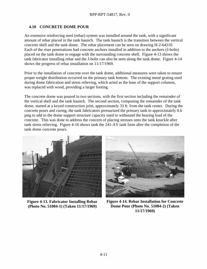
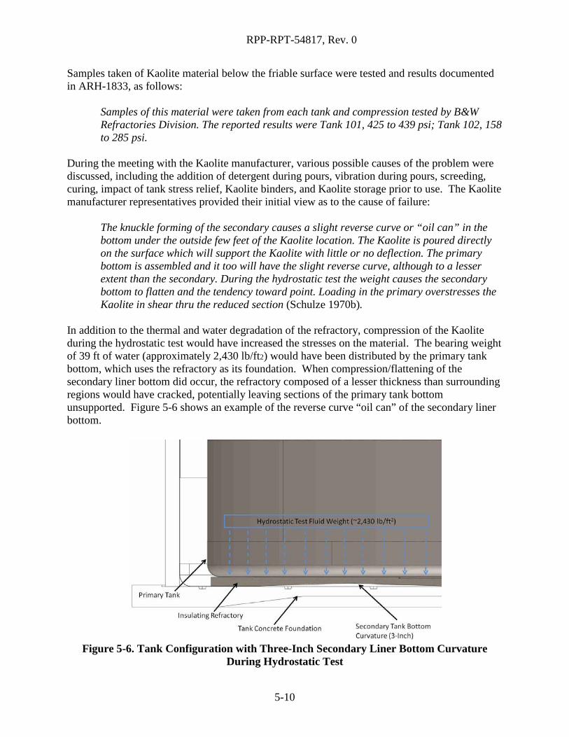
4.10 CONCRETE DOME POUR
An extensive reinforcing steel (rebar) system was installed around the tank, with a significant amount of rebar placed in the tank haunch. The tank haunch is the transition between the vertical concrete shell and the tank dome. The rebar placement can be seen on drawing H-2-64310. Each of the riser penetrations had concrete anchors installed in addition to the anchors (J-bolts) placed on the tank dome to engage with the surrounding concrete shell. Figure 4-13 shows the tank fabricator installing rebar and the J-bolts can also be seen along the tank dome. Figure 4-14 shows the progress of rebar installation on 11/17/1969. Prior to the installation of concrete over the tank dome, additional measures were taken to ensure proper weight distribution occurred on the primary tank bottom. The existing metal grating used during dome fabrication and stress relieving, which acted as the base of the support columns, was replaced with wood, providing a larger footing. The concrete dome was poured in two sections, with the first section including the remainder of the vertical shell and the tank haunch. The second section, composing the remainder of the tank dome, started at a keyed construction joint, approximately 33 ft. from the tank center. During the concrete pours and curing, the tank fabricators pressurized the primary tank to approximately 0.6 psig to add to the dome support structure capacity used to withstand the bearing load of the concrete. This was done to address the concern of placing stresses onto the tank knuckle after tank stress relieving. Figure 4-16 shows tank the 241-AY tank farm after the completion of the tank dome concrete pours.
Figure 4-13. Fabricator Installing Rebar (Photo No. 51084-1) (Taken 11/17/1969)
Figure 4-14. Rebar Installation for Concrete Dome Pour (Photo No. 51084-2) (Taken
11/17/1969)
4-11

RPP-RPT-54817, Rev. 0
4.11 TANK APPURTENANCES
After completing the concrete pours, the tank dome support structures were disassembled and removed in pieces through the existing 42 in. diameter riser penetrations. The equipment to be placed on the interior of the tank was then installed, including the tank airlift circulators, thermocouples, steam coil, dry wells, and annulus pump pit and leak detection pump pit drains. These pieces of equipment were welded to the existing penetrations that had previously been installed on the tank dome prior to the tank stress relief. Figure 3-25 shows the in-tank equipment installation in tank AY-102.
Figure 4-16. Concrete Dome Complete, Looking Southwest (Photo No. 51305-13)
(Taken 12/22/1969)
Figure 4-15. Center of Dome and Completed Internals of Tank AY-102 (Photo No. 51660-18) (Taken 2/20/1970)
4-12

RPP-RPT-54817, Rev. 0
5.0 CONSTRUCTION ISSUES
This section provides a detailed view of the major construction issues identified during the fabrication of tank AY-101. This information has been compiled from a review of the Quality Assurance (QA) daily logbooks, inspection sheets, correspondence, drawings, photos, and other construction records. The focus of this review was the secondary liner and primary tank bottom fabrication/testing, and the refractory.
5.1 WELD REJECTION AND NON-DESTRUCTIVE EXAMINATION
A quantitative comparison of welding success on tanks AY-101 and AY-102 is shown in Table 5-1. A similar comparison was completed and included within RPP-ASMT-53793. Re-analysis of the tank AY-101 and AY-102 primary bottom weld maps was completed as a part of this extent of condition effort to ensure accuracy and consistency. The results are nearly identical to those previously tabulated with some minor discrepancies resulting from omission of the center dollar plate in the primary tank bottom.
Table 5-1. 241-AY Tank Farm Primary Tank Bottom Weld Comparison Tank AY-101 Tank AY-102
Feet of Weld (ft)
Reject Rate (%)
per Repair Cycle
Total Reject Rate (%)
Feet of Weld (ft)
Reject Rate
(%) per Repair Cycle
Total Reject Rate (%)
Weld prior inspection 672 N/A N/A 673 N/A N/A
Weld rejected after original weld 67 10.0% 10.0% 229 34.0% 34.0%
Weld rejected after first repair 7 10.4% 10.0% 86 37.6% 34.9%
Weld rejected after second repair 1 14.3% 10.1% 27 31.4% 34.6%
Weld rejected after third repair 1 100.0% 10.2% 1 3.7% 33.8%
Weld rejected after fourth repair 0 N/A N/A 0 N/A N/A
Total weld rejections 76 343
Total weld 748 1016
Overall weld rejection rate 10.2% 33.8%
Workers had comparatively more success welding tank AY-101 at 10.2% overall weld rejection compared to 33.8% overall weld rejection for tank AY-102. The maximum number of times a weld section was repaired in the 241-AY tank farm was four, with one weld section repaired four times in both tanks AY-101 and AY-102.
5-1

RPP-RPT-54817, Rev. 0
In a letter from E.S. Davis (RPP-ASMT-53794, Section 1.8) the following is stated:
“…through discussion, [we] have attempted to improve the quality of the fabricator’s welding…specifically to reduce the amount of repairs to welds on primary tanks. These meetings have not resolved what we feel is the primary problem- -the lack of quality control by the fabricator. Recently, we have increased our inspection coverage of the welding of the 101 tank bottom. Whether or not this detail inspection coverage is the primary cause, the resulting number of weld repairs decreased from a ratio of 51% film repair incident on tank 102 to a ratio of less than 10% film repair incident on tank 101.”
On February 14, 1969 in the QA daily logbook, it was noted that welding on tank AY-101 appeared to be of superior quality than that seen in tank AY-102. All welding was performed using procedures qualified in accordance with Section IX, ASME Boiler and Pressure Vessel Code. Welders and welding operators were also qualified in accordance with Section IX, ASME Code (HWS-7789). Welds were rejected or accepted based on non-destructive examination (NDE) methods. The level of NDE varied between the primary tank and secondary liner as well as with elevation of the tank. The change in NDE due to elevation was based on the planned use of the tank to contain waste up to a specific elevation. Table 5-2 provides a summary of the NDE used to ensure the pedigree of the primary tank and secondary liner. The radiography inspection on the primary tank and secondary liner bottoms was completed prior to lowering the bottom. See Appendix B for weld maps of the complete primary tank and secondary liner of tank AY-101.
5-2

RPP-RPT-54817, Rev. 0
Table 5-2. 241-AY Tank Farm Non-Destructive Examinations Used During Construction
Primary Tank Inspections Secondary Liner Inspections
Tank Bottom
• 100% radiography • Magnetic particle • 100% visual • Vacuum leak test • Hydrostatic leak test
• 100% radiography • Magnetic particle • 100% visual • Vacuum leak test
Bottom Knuckle
• 100% radiography • Magnetic particle • 100% visual • Vacuum leak test • Hydrostatic leak test
• 100% radiography • Magnetic particle • 100% visual • Vacuum leak test
Vertical Wall
• 100% radiography • Magnetic particle • 100% visual • Hydrostatic leak test
• Random spot radiography • Magnetic particle • 100% visual
Upper Knuckle and Tank Dome
• 100% Visual Inspection • Hydrostatic leak test of upper
knuckle and the horizontal weld connecting the dome and upper knuckle
• 100% Visual Inspection
5.2 REFRACTORY
Material Selection 5.2.1
The original refractory material specified in the 241-AY tank farm construction specification was to be Kaolite 20. Later testing, conducted by Battelle Northwest Laboratories, proved that Kaolite 2200LI met structural and insulating requirements of the project. A change request was initiated on 9/4/1968 (see App Figure C-2), which stated the following:
“Please initiate a change to use Kaolite 2200-LI instead of Kaolite 20 as the insulating concrete in the two new storage tanks. Tests by Battelle Northwest have shown that Kaolite 2200-LI meets structural and insulation requirements for this project. In addition, Kaolite 2200-LI is more resistant to sulfate attack than Kaolite 20.”
The Record of Design Change that documents the change from Kaolite 20 to Kaolite 2200LI is included as App Figure C-3 in Appendix C.
5-3

RPP-RPT-54817, Rev. 0
Refractory Thickness Variation 5.2.2
Prior to pouring the refractory in tank AY-101, issues associated with the installation on the warped secondary liner bottom had to be addressed. The secondary liner bottom was out of tolerance with respect to peak-to-valley and slope requirements in six areas, as noted in Section 5.4, creating the potential for a thinner refractory which would violate the 8 in. thickness requirement. The path forward to deal with the abnormality was based on the known high points (approximately 3 in.) on the secondary liner bottom, and the minimum thickness that could be tolerated to perform tank stress relieving. This path forward was documented in PUREX Tank Farm Expansion IAP-614 Minimum Thickness Insulating Concrete (Graves 1969a, RPP-RPT- ASMT-53794, Section 1.10).
“Confirming discussions with A. Short and E.S. Davis, five inches of Kaolite insulating concrete is sufficient to protect the base concrete during stress-relieving of the primary tank. This judgment is based upon the Battelle report BNWL-797, detail requirements on the similar project at Savannah River, tests run by Nooter in Saint Louis for the Savannah River project, and Vitro calculations. It was with this information in mind that a “humped” bottom 3-in. in height could be accepted since this still left 5 in. of insulating available. The condition at the air inlet pipes requires a minimum thickness as shown, but in this limited area the steel plate of the secondary tank will spread the heat flow and thus lessen the intensity to a satisfactory level.”
As previously noted, decisions to continue with the project with tank flatness issues present in the secondary liner bottom plates were documented in Schulze (1969a) (RPP-ASMT-53794, Section 1.18). This letter documented verbal agreements reached on February 13, 1969, and made multiple changes to what was originally allowed in the construction specification, which included:
1. “The Kaolite thickness will be governed by the cross-section, as shown on drawing H-2-64307, ‘Structural Insulating Concrete Plan and Details.’ Thus, the minimum thickness of Kaolite over any area in the tank bottom will be 5 in.”
Installation of the refractory was discussed with the contractor. Highlights of the meeting are documented in Cardwell (1969a) (RPP-ASMT-53794, Section 1.4), stating that:
1. “The shell bottom is out-of-tolerance with respect to peak-to-valley and slope requirements in several places. The out-of-tolerance conditions are acceptable provided the contractor assumes responsibility for the changes in elevation of the primary tank caused by these conditions.
2. Placing of Kaolite is to begin at the greatest out-of-tolerance location of the secondary shell.
5-4

RPP-RPT-54817, Rev. 0
3. Any visual cracks, fractures in or damages to the Kaolite will be repaired as recommended by the Kaolite manufacturer.”
The refractory in tank AY-101 was completed on March 26, 1969, with QA checks performed to ensure that a minimum thickness of 5 in. was achieved. A QA checklist from March 29, 1969 (HES QA Report (1969, RPP-RPT-53794, Section 1.13) documents that a minimum thickness of 7 in., a maximum thickness of 10-1/2 in., and average thickness of 9 in. were achieved. It is known that the secondary liner of tank AY-101 had one 3 in. bulge, as discussed in Section 5.4.1. Minimum thickness of 7 in. is likely found at the 3 in. bulge location. Likewise, the average and maximum thicknesses would be found in flatter regions of the tank to compensate for the 3 in. rise caused by bulging in the 7 in. thick location. This height was confirmed by a design change to the primary tank bottom to account for this increased height. Design Change 2124-17, dated April 7, 1969, revised the cleat detail on drawing H-2-64449, Section A-A (Cardwell 1969b, RPP-ASMT-53794, Section 1.5). The reason for the change was documented as:
“The difference in elevation between the secondary and primary tank bottoms is increased approximately two inches because of variations in the level of the secondary tank bottoms. This, in turn, raises the cleats within the container ring (see Dwg. H-2-64449, Detail 6), causing the 3 in.-high cleats to become ineffective.”
The tank cleats are designed to help center the primary tank bottom onto the refractory after welding was completed. The underside of the primary tank has 18 cleats welded in a circular pattern positioned to clear the container ring (i.e., air distribution ring), which is welded in the center of the secondary liner. Figure 5-1 shows the orientation represented on drawing H-2-64449 to illustrate the configuration and purpose of the cleats.
Figure 5-1. Primary Tank Bottom Cleats Engaged in Container Ring
The configuration in Figure 5-1 does not depict the actual condition faced by the tank fabricator due to the increased thickness in the refractory. Insufficient engagement between the cleats and the 7-3/4 in. tall container ring would have inhibited the fabricator’s ability to center the primary tank bottom and prevent any shift during construction. With a refractory thickness of
5-5

RPP-RPT-54817, Rev. 0
approximately 10 in., the original cleats with a height of 3 in. would have provided an engagement of no more than 3/4 in. Figure 5-2A is a diagram of the original design condition. Figure 5-2B illustrates the field condition without revision to the cleats caused by the increased refractory in tank AY-102. Figure 5-2C shows the actual conditions after the design change to the cleats based on construction records review.
Figure 5-2. Primary Tank Bottom Cleat Design Change Summary
5-6

RPP-RPT-54817, Rev. 0
Evaluation of Refractory After Tank Hydrostatic Test 5.2.3
Following stress relief, the primary tank was hydrostatically tested. While no specific notes were discovered directly after hydrostatic testing for AY-101, an inspection following AY-102 hydrostatic testing identified cracking in the refractory. This observation was noted in an October 15, 1969 inspection report (HES QA Report 1969, RPP ASMT-53794, Section 1.13) as follows:
“Kaolite insulating concrete is somewhat fractured, presumably from weight of water used in hydro.”
Photographic evidence and future inspections indicated similar conditions in tank AY-101. Following further refractory inspection, it was the opinion of the individual performing the inspection that the surface cracking and spalling of concrete was a direct result of stresses incurred during post-weld stress relief of the primary tank. More specifically, tensile stresses in the periphery of the refractory and stresses produced by skin friction from expansion and contraction of primary tank (Lien 1969, RPP-ASMT-53794, Section 1.16). While no specific dimensions were captured during tank AY-101 stress relief, movement of the tank AY-102 primary was measured at 7-1/16 in. of expansion in the north-south direction and 7-1/8 in. in the east-west direction, as documented in the HES QA Report (1969) (RPP-ASMT-53794, Section 1.13). Similar growth is assumed to have occurred in tank AY-101. Growth of the tank AY-101 primary was described in a note on a QA checklist during post-weld stress relieving (HES QA Report (1969), RPP-ASMT-53794, Section 1.13) on November 5, 1969, which stated:
“During the stress relief cycle, two insulation holding bands broke as a result of thermal growth of the tank.”
A letter from D.G. Lien was written on July 10, 1970 describing his visit to inspect the refractory (Lien (1970), RPP-ASMT-53794, Section 1.17). The following was noted regarding the condition of the tank AY-101 refractory relative to tank AY-102:
“…it was the general opinion that the refractory concrete in Tank 101 was in better condition than that in tank 102… repair work to Tank 101 was subject to re-evaluation…”
As a part of determining necessary actions, PDM performed a stress analysis assuming 6 and 12 in. of knuckle support loss. The results of the analysis showed that the structure could likely tolerate 6 in. of foundation deterioration, but that support losses greater than 6 in. would put the tank in questionable status. It was determined that modifications to tanks AY-101 and AY-102 needed to include replacing the outer 21 in. of the refractory concrete and replacing it with reinforced, shrink-compensating concrete. The outer circumference of the refractory would then be secured with a steel ring to prevent outward movement of the refractory (ARH-1833, Investigation of the 241-AY Insulating Refractory Task Force Report).
5-7

RPP-RPT-54817, Rev. 0
A minimum of 21 in. of refractory was removed and replaced with reinforced concrete (H-2-35299, Structural Modification Insulating Concrete Plan & Details). On July 21, 1970, Kaolite removal began on tank AY-101, using various tools, including hammers, chisels, chainsaws, and pneumatic-powered air chisels. Figure 5-3 shows the refractory removal process in preparation for concrete installation. Inspection of the Kaolite during repairs in tank AY-101 (Schulze (1970a), RPP-ASMT-53794, Section 1.21) noted that friable material ranging from 1/4 in. to 1/2 in. thick, and cracking was visible in the refractory. Figure 5-4 shows chipped out refractory in tank AY-101 during repair efforts. Figure 5-5 shows a different region of tank AY-101 where the refractory was chipped out. Void space between the refractory and primary tank bottom is visible. The caption of photo 52788-8 (Figure 5-5) commented on this void space as follows:
“Station 175 – Note upper tank drawn up – where this much void appeared, it was purposely maintained after pour to allow normal resettling of tank if required.”
During prior construction of tank AY-102, evidence was found in the daily logbook records, on June 30, 1970, indicating that these similar void spaces were filled with a styrene foam material to preserve the void space. While the use of foam to temporarily maintain the void space in tank AY-101 before pouring was not explicitly stated in reviewed documents and logbooks, it is
Figure 5-3. Tank AY-101 Refractory Repair
Figure 5-5. Tank AY-101 Refractory Repair (Photo No. 52788-8) (Taken 8/3/1970)
Figure 5-4. Tank AY-101 Refractory Repair (Photo No. 52720-3) (Taken 7/23/1970)
5-8

RPP-RPT-54817, Rev. 0
assumed that this same method was applied. The specific type of foam used and the exact locations it was applied to relative to the tank is unknown. It is likely that chlorofluorocarbons (CFC) were in the styrene foam used at the time of 241-AY tank farm construction. The CFCs were blowing agents and would be trapped in the expanded foam. CFCs became heavily regulated in the late 1970s because of their ozone-depleting effects and were phased out starting in the 1980s. It is possible that any potential CFCs trapped in the foam used in tank AY-101 and AY-102 repairs would decompose under the conditions of heat and radiation and release decomposition products that could be corrosive to the tank steels. These include chlorine free radicals and chlorodifluoracetic acid (CML-SSP Working Paper 2001.002, RPP-ASMT-53794, Section 1.7). It is possible that some localized damage could occur in the area of these repairs. Manufacturer representatives for Kaolite were at the construction site (QA logbook entry on July 21, 1970) for inspection of tanks AY-101 and AY-102. It was noted that the refractory for both tanks had a friable surface at the top that was not homogenous with the balance of the Kaolite. X-ray diffraction (XRD) analyses performed on samples taken from the top layer of friable material identified only calcium carbonate and anorthite (anhydrous calcium aluminum silicate mineral). The friable material had little or no compressive strength and would break up immediately and crumble under impact or compression. The friable layer in tank AY-101 varied from about 1/4 in. to 1/2 in. thick; whereas in tank AY-102, it generally varied from 3/4 in. to 1-3/4 in. thick. Tank AY-102 was noted to have one area in particular that contained a soft punky material that had no strength whatsoever and evidence of one or two other small locations of similar material (Schulze 1970b, RPP-ASMT-53794, Section 1.22). Punky is defined as a refractory lining that is abnormally soft and friable (API-936, Refractory Installation Quality Control – Inspection and Testing Monolithic Refractory Linings and Materials). Present-day manufacturers of refractory Kaolite warn against a phenomenon identified as alkali hydrolysis, also known as carbonation, which is the formation of calcium carbonate (CaCO3). This formation is caused by the reaction of lime in cement with carbon dioxide in the atmosphere. The hydrolysis reaction breaks down the cement bond, which creates a volume expansion, weakening the refractory lining surface. The Pocket Manual Refractory Materials (Routschka 2007) states:
The following general rules should be observed if longer time periods have elapsed (weeks or months) until commissioning. The furnace must be subjected to draft conditions so that sufficient ventilation prevails. This will ensure that humidity is not too high and no hydrothermal conditions arise. Otherwise alkaline hydrolysis is possible when using refractory castables. The result will be complete carbonation or destruction of the lining.
The refractory in both tanks AY-101 and AY-102 may have undergone a level of alkali hydrolysis taking into consideration the steam discharge observed during initiation of stress relief, the noted friable material, and the reduction in compressible strength.
5-9
RPP-RPT-54817, Rev. 0
Samples taken of Kaolite material below the friable surface were tested and results documented in ARH-1833, as follows:
Samples of this material were taken from each tank and compression tested by B&W Refractories Division. The reported results were Tank 101, 425 to 439 psi; Tank 102, 158 to 285 psi.
During the meeting with the Kaolite manufacturer, various possible causes of the problem were discussed, including the addition of detergent during pours, vibration during pours, screeding, curing, impact of tank stress relief, Kaolite binders, and Kaolite storage prior to use. The Kaolite manufacturer representatives provided their initial view as to the cause of failure:
The knuckle forming of the secondary causes a slight reverse curve or “oil can” in the bottom under the outside few feet of the Kaolite location. The Kaolite is poured directly on the surface which will support the Kaolite with little or no deflection. The primary bottom is assembled and it too will have the slight reverse curve, although to a lesser extent than the secondary. During the hydrostatic test the weight causes the secondary bottom to flatten and the tendency toward point. Loading in the primary overstresses the Kaolite in shear thru the reduced section (Schulze 1970b).
In addition to the thermal and water degradation of the refractory, compression of the Kaolite during the hydrostatic test would have increased the stresses on the material. The bearing weight of 39 ft of water (approximately 2,430 lb/ft2) would have been distributed by the primary tank bottom, which uses the refractory as its foundation. When compression/flattening of the secondary liner bottom did occur, the refractory composed of a lesser thickness than surrounding regions would have cracked, potentially leaving sections of the primary tank bottom unsupported. Figure 5-6 shows an example of the reverse curve “oil can” of the secondary liner bottom.
Figure 5-6. Tank Configuration with Three-Inch Secondary Liner Bottom Curvature
During Hydrostatic Test
5-10

RPP-RPT-54817, Rev. 0
Further detail of refractory repair can be found in the daily logbook key event table in Appendix A, starting on 7/21/1970 and ending on 8/4/1970. The QA log entry from August 4, 1970 indicated that pouring of the perimeter concrete ring support in tank AY-101 was completed. Figure 5-7 shows the finished perimeter concrete support ring as seen in tank AY-102. The photo is representative of the finished concrete support ring in tank AY-101.
Sampling 5.2.4
During refractory repair, samples of removed tank AY-101 periphery refractory were sent to Willard Smith, Inc. (WSI) for testing and results were presented in a September 25, 1970 letter (WSI (1970), RPP-ASMT-53794, Section 1.12). The test parameters in the letter are as follows:
“Three inch thick cut pieces approximately 10” x 10” were saturated with water and then frozen at approximately 10°F; then heated to 500°F to remove all water. Some pieces were wet only 1/4” deep and 3/4” deep.
After this treatment, pieces of each type were cut into following shapes and subjected to a constant 2000# load applied to steel plates on top and bottom of samples; horizontal force was applied to top plate to note effects.
For samples that were only wetted, the results of the vertical load capability remained above 222 lbs/in.2, and horizontal load failure was inconclusive (WSI 1970, RPP-ASMT-53794, Section 1.24). The results of the laboratory testing are shown in Table 5-3.
Figure 5-7. Tank AY-102 Finish Perimeter Concrete Support Ring
5-11

RPP-RPT-54817, Rev. 0
Table 5-3. Kaolite Laboratory Test Results After Freezing Samples at 10°F Sample Wetted
Depth (in.) Sample Size
Compressive Load Applied
(psi)
Withstood Vertical
Load
Withstood Horizontal
Load 0.25 3-in. × 3-in. × 3-in. thick 222 Yes No 0.25 3-in. × 4-in. × 3-in. thick 167 Yes No 0.25 3-in. × 6-in. × 3-in. thick 111 Yes No 0.75 3-in. × 3-in. × 3-in. thick 222 Yes No 0.75 3-in. × 4-in. × 3-in. thick 167 Yes No 0.75 3-in. × 6-in. × 3-in. thick 111 Yes No
Complete 3-in. × 3-in. × 3-in. thick 222 No N/A Complete 3-in. × 4-in. × 3-in. thick 167 No N/A Complete 3-in. × 6-in. × 3-in. thick 111 Yes No
The completely wetted samples were then cut into 2-1/2 in. cubes and sent to Northwest Testing Laboratory for vertical and horizontal load testing to destruction. The results are as follows:
1. “Vertical Loading A. 149#/in.2 B. 156
2. Horizontal Loading C. 259#/in.2 D. 266
Conclusion: Vertical load carrying capability is considerably lessened by freezing; horizontal load carrying capability is not appreciably lessened by freezing.”
Furthermore, it is stated:
“My opinion of these tests, is that it thoroughly substantuates (sic) our original presumption that freezing of Kaolite 2200 LI, after proper curing procedures have been completed, results in a severely lowered load carrying capability.”
The tank AY-101 refractory installation began on March 17, 1969 and was completed on March 26, 1969, as noted in the QA daily logbook and Appendix A. During this time, the refractory was subjected to a low temperature of 26°F on one occasion and water saturation on another. Based on this evidence, it is possible that the refractory experienced degradation as a result of failed weather protection methods. Later post-weld stress relief activities would have exacerbated the existing flawed condition where excess moisture would leave behind voids in the material following evaporation, reducing overall material strength. See Table 5-4 for detail of
5-12

RPP-RPT-54817, Rev. 0
the refractory installation timeline, including key temperature and weather event details, from Appendix A.
Table 5-4. Tank AY-101 Refractory Installation and Weather Event Details Date Comment Event Type6
3/12/1969 Crew setting forms in tank AY-101 for Kaolite placement. Installed protective cover on tank CM
3/17/1969
Outside temp 54 degrees F. PDM - started placing Kaolite insulation at 9:30 AM using 15 1/2 gal water / 5-40# bags of kaolite. Inside temp of tank was 60 degrees F. Water/ratio of mix was satisfactory. Section 5 - sample taken at 10:30 AM of material after the material was vibrated in place. Section 9 - sample taken at 2:30 PM after material was vibrated in place. Inside tank temp 70 degrees F. Completed at 3:45 PM. Form work for section 1 was moved from section 5.
CM
3/18/1969
Temp inside tank at 9:15 a.m. was 63 degrees F. Started placing Kaolite insulation in section 13 at 9:15 a.m. and completed at 11:45 a.m. Started section 4 at 12:30 p.m. and completed at 3:05 p.m. Started section 7 at 3:10 p.m. and completed at 6:00 p.m. Started sec 17 at 6:00 p.m. and completed at 8:10 p.m. Samples taken of all sections placed. Two slight hairline cracks have appeared in section 13. Using 15 1/2 gal water / 5-40# bags of mix. Mix appeared to be acceptable.
CM
3/19/1969
Temperature inside tank AY-101 at 9:20 a.m. was 68 degrees F. Started placing Kaolite insulation in section 3 at 8:15 a.m. using 15 1/2 gal / batch mix. Sample taken at 9:20 AM. Section completed at 11:00 a.m. Started section 8 at 11:00 a.m. Sample taken at 1:45 p.m. Temperature inside the tank was 86 degrees F. Section 8 completed at 2:20 p.m. Started section 21 at 2:25 p.m. Sample taken 4:45 p.m. Completed section 21 at 5:10 p.m.. Started section 2 at 5:20 p.m. using 15 3/4 gal / batch mix. The warm day had further removed moisture from the bags of Kaolite material. Sample taken section 2 at 7:40 p.m. Temperature was 60 degrees. Section 2 completed at 7:45 p.m. Started section 11 at 7:45 p.m. Sample taken at 9:15 p.m. Temperature was 48 degrees F. Completed section at 10:25 p.m. All samples taken were from materials vibrated in place.
CM
6 CM: General Construction Milestone, CI: Construction Issue
5-13

RPP-RPT-54817, Rev. 0
Table 5-4. Tank AY-101 Refractory Installation and Weather Event Details Date Comment Event Type6
3/20/1969
Started placing Kaolite insulation in section 15 at 8:50 a.m. using 15 1/2 gal / batch. Difficulty was experienced with placing material due to dryness. At 9:30 a.m., mix was changed to 15 3/4 gal / batch. Sample taken at 10:30 a.m. Temperature inside tank AY-101 at 10:30 a.m. was 72 degrees F. Completed section 15 at 1:30 pm. Started section 12 at 11:40 a.m. Sample taken at 1:30 p.m. Temperature in tank was 85 degrees F. Completed section 12 at 3:15 p.m. Start section 25 at 3:20 p.m. Samples section 25 at 5:25 p.m. Temperature in tank was 74 degrees F. Completed section 25 at 6:10 p.m. Started section 19 at 6:10 p.m. Sampled section 6 at 11:30 p.m. Temp in tank was 58 degrees. Completed section 6 at 11:50 p.m. All batches from 9:50 p.m. on used 15 3/4 gal. Mr. Trumball from B&W visited the jobsite. Discussion on mix, mixing time, placing, density and thermal characteristics were made during his visit.
CM
3/21/1969
Started placing Kaolite insulation in section 16 at 9:00 a.m. Sample taken at 10:20 a.m. Temperature at 11:00 a.m. was 68 degrees F. Completed section 16 at 11:45 a.m. Started section 29 at 11:45 a.m. Sample taken at 2:00 p.m. Temperature inside tank at 2:00 p.m. was 81 degrees F. Sample slightly dry. Humidity inside tank very high and very warm. Completed section at 11:45 a.m. Started section 23 at 3:40 p.m. Sample taken at 3:50 p.m. Temperature at 11:00 was 80 degrees F. Completed section 23 at 6:30 p.m. Started section 20 at 6:35 p.m. Sample taken at 9:45 p.m. One batch too wet made contractor remove from form. This delayed completion of section unil10:45 p.m. Temperature at time of sample was 60 degrees F. All batches except one mentioned above used 15 3/4 gal water.
CM
3/22/1969
Over the weekend the protective covering was ripped off the tank and the Kaolite insulation was exposed to the weather for the rest of the weekend. It is surmised that the covering was ripped off last Saturday afternoon after all sections placed had at least 18 hours of satisfactory curing period. The insulation was subjected to low temp. of 26 degrees on Sunday night. At this point no detectable damage is evident to the insulation placed to date.
CI
5-14
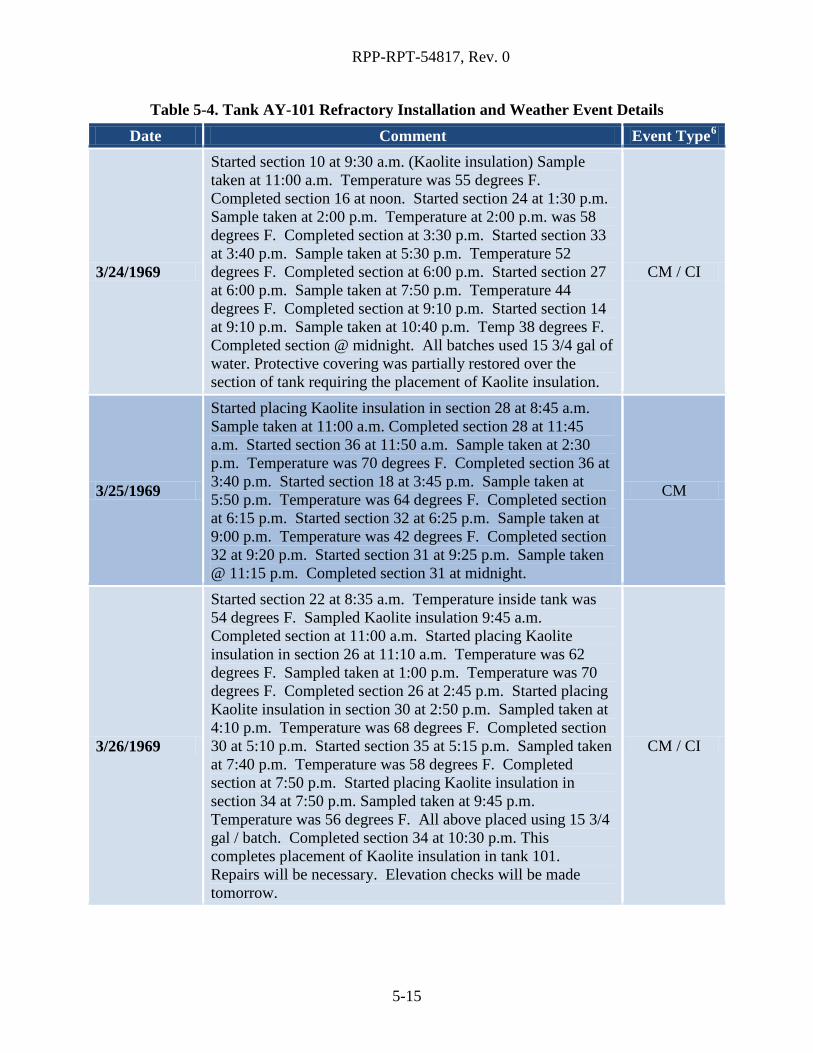
RPP-RPT-54817, Rev. 0
Table 5-4. Tank AY-101 Refractory Installation and Weather Event Details Date Comment Event Type6
3/24/1969
Started section 10 at 9:30 a.m. (Kaolite insulation) Sample taken at 11:00 a.m. Temperature was 55 degrees F. Completed section 16 at noon. Started section 24 at 1:30 p.m. Sample taken at 2:00 p.m. Temperature at 2:00 p.m. was 58 degrees F. Completed section at 3:30 p.m. Started section 33 at 3:40 p.m. Sample taken at 5:30 p.m. Temperature 52 degrees F. Completed section at 6:00 p.m. Started section 27 at 6:00 p.m. Sample taken at 7:50 p.m. Temperature 44 degrees F. Completed section at 9:10 p.m. Started section 14 at 9:10 p.m. Sample taken at 10:40 p.m. Temp 38 degrees F. Completed section @ midnight. All batches used 15 3/4 gal of water. Protective covering was partially restored over the section of tank requiring the placement of Kaolite insulation.
CM / CI
3/25/1969
Started placing Kaolite insulation in section 28 at 8:45 a.m. Sample taken at 11:00 a.m. Completed section 28 at 11:45 a.m. Started section 36 at 11:50 a.m. Sample taken at 2:30 p.m. Temperature was 70 degrees F. Completed section 36 at 3:40 p.m. Started section 18 at 3:45 p.m. Sample taken at 5:50 p.m. Temperature was 64 degrees F. Completed section at 6:15 p.m. Started section 32 at 6:25 p.m. Sample taken at 9:00 p.m. Temperature was 42 degrees F. Completed section 32 at 9:20 p.m. Started section 31 at 9:25 p.m. Sample taken @ 11:15 p.m. Completed section 31 at midnight.
CM
3/26/1969
Started section 22 at 8:35 a.m. Temperature inside tank was 54 degrees F. Sampled Kaolite insulation 9:45 a.m. Completed section at 11:00 a.m. Started placing Kaolite insulation in section 26 at 11:10 a.m. Temperature was 62 degrees F. Sampled taken at 1:00 p.m. Temperature was 70 degrees F. Completed section 26 at 2:45 p.m. Started placing Kaolite insulation in section 30 at 2:50 p.m. Sampled taken at 4:10 p.m. Temperature was 68 degrees F. Completed section 30 at 5:10 p.m. Started section 35 at 5:15 p.m. Sampled taken at 7:40 p.m. Temperature was 58 degrees F. Completed section at 7:50 p.m. Started placing Kaolite insulation in section 34 at 7:50 p.m. Sampled taken at 9:45 p.m. Temperature was 56 degrees F. All above placed using 15 3/4 gal / batch. Completed section 34 at 10:30 p.m. This completes placement of Kaolite insulation in tank 101. Repairs will be necessary. Elevation checks will be made tomorrow.
CM / CI
5-15

RPP-RPT-54817, Rev. 0
Table 5-4. Tank AY-101 Refractory Installation and Weather Event Details Date Comment Event Type6
4/7/1969 Considerable rainfall fell over the weekend with 3-4 inches water in secondary tank on the outside of the Kaolite insulation.
CI
Waste Compatibility 5.2.5
As previously discussed, the primary tank was designed to rest on an 8-in. thick layer of refractory that protected the secondary liner bottom and the structural concrete foundation from excessive thermal stresses during the primary tank stress relieving and during high-heat waste storage. The refractory was found damaged after stress relieving and hydrostatic test as discussed in Section 5.2.3. The refractory used in 241-AY tank farm is Kaolite 2200-LI, which is classified as a general purpose, lightweight castable refractory material. The Kaolite series refractory used a calcium aluminate binder, with the low iron (LI) series having low iron content.
5.2.5.1. Waste Compatibility Testing
The DST refractory is generically called “kaolite,” which is a general term for a castable refractory that contains a binder of calcium aluminosilicate. Each series of DST used a different kaolite formulation. The construction documentation specified specific properties, including insulating properties, minimum compressive strength, and chemical resistance to tank waste. Kaolites discussed in this section include Kaolite 20, the material originally specified for 241-AY tank farm; Kaolite 2200-LI, which was the material actually used in 241-AY tank farm; and Kaolite 2000, which was tested and found to lack chemical resistance in the air-dried form but still used later in 241-AZ tank farm.
The chemical resistance of all the DST refractory was examined in 2003 through a compilation of existing documentation, testing, and analysis, documented in RPP-19097. Page 3 of RPP-19097 states: “During the preparation of an engineering evaluation in response to PER 2003-3066, a 1971 Battelle Northwest Laboratories test report (BNWL-B-56, Evaluation of Kaolite-2000 Insulating Concrete) was found in the files of an engineer” (now found in RPP-19097, as Attachment 7). The test report described samples of Kaolite 2000 that were air-dried and samples that were heated to 1,100°F and then both immersed in simulated tank waste. The heated samples maintained most of their compressive strength after immersion in the waste, but the air-dried samples “decomposed,” so no compressive strength values were obtained. The concern was raised that the bottom surface of the refractory would have been much cooler (calculated as only 180°F) during the heat treatment of the primary tank and therefore vulnerable to a tank waste leak.
Kaolite 2000 is the material used for the refractory in 241-AZ tank farm. The refractory used in 241-AY tank farm, Kaolite 2200-LI, is similar. A comparison of some material properties and chemical composition for both refractory materials is provided in Table 5-5. Kaolite 2200-LI has lower iron oxide and calcium oxide content and higher aluminum oxide, silicon dioxide, titanium dioxide, and magnesium oxide content than Kaolite 2000.
5-16

RPP-RPT-54817, Rev. 0
Table 5-5. Comparison of Properties for Kaolite 2000 and Kaolite 2200-LI
Refractory Type Kaolite 2000
Kaolite 2200-LI
Refractory Type
Kaolite 2000
Kaolite 2200-LI
Density-molded (lb/ft3) 86 83 Chemical analysis (as wt% oxide)
SiO2 36.4 37.4
Density-fired (lb/ft3) 55 49 Al2O3 34.7 40.7
Fe2O3 5.6 0.9
Cold crushing strength (psi) TiO2 1.2 1.7
220°F 440 260 CaO 21.1 18.6
1,000°F 375 260 MgO 0.2 0.4
1,500°F 350 260 Na2O 0.3 0.3 From Babcock & Wilcox insulating castables datasheet found in IAP-614 project files.
5.2.5.2. Testing of Kaolite 2200-LI Refractory
The refractory for 241-AY tank farm was originally specified to be Kaolite 20, manufactured by Babcock and Wilcox at the time and used at the Savannah River Site. Kaolite 20 was tested by Battelle Northwest Laboratory in 1968 under various temperature, moisture, and waste contact conditions (BNWL-797, Evaluation of Kaolite-20 Insulating Castable, included as Attachment 3 of RPP-19097).
Tests were done typically using 2-in. cubes. Samples met compressive strength requirements (200 psi) under all conditions. Kaolite 2200-LI was substituted for Kaolite 20, with the stated reason that Kaolite 2200-LI is more resistant to waste that contains sulfates (RPP-19097, Attachment 4). Supplementary testing in 1968 was done for Kaolite 2200-LI following the protocols of BNWL-797.
The testing was documented in an unpublished report found later in project records and included as Attachment 5 of RPP-19097. The attachment, entitled “Evaluation of Kaolite 2200,” does not have a document number and the LI notation is only handwritten on the title page. There is a castable refractory produced designated as Kaolite 2200, which is not low in iron oxide content (2.4 wt%). Therefore, there is some uncertainty about which Kaolite 2200 refractory material was actually tested by Battelle.
The material reported as Kaolite 2200-LI met the compressive strength requirements, even after samples were immersed in simulated tank waste. The simulant used for testing both Kaolite 20 and samples reported as Kaolite 2200-LI was a complex solution, moderately caustic, high in nitrite, and lower in nitrate and carbonate than current 241-AY tank farm supernatant (see Table 5-6). Note that, although BNWL-797 specified two stimulant compositions for testing Kaolite 20, identified as Table I and Table II, only Table II solutions were used in testing the
5-17

RPP-RPT-54817, Rev. 0
reported Kaolite 2200-LI samples. That composition is shown in Table 5-6 along with current compositions of waste in tanks AY-101 and AY-102.
Table 5-6. Synthetic Waste Solution Tested on Kaolite 20 and Kaolite 2200-LI
Chemical
Table II Stored Boiling Waste Compositiona
M
Current Tank AY-102 Supernatant Compositionb
M
Current Tank AY-101 Supernatant Compositionc
M
Fe 0.10 7.5E-05 8.79E-06 Al 0.12 0.30 8.50E-02 Na 2.0 6.39 2.65 Cr 0.005 3.7E-03 3.16E-03 Ni 0.002 1.2E-04 2.88E-05 Ca 0.001 2.2E-04 1.12E-04 Zr 0.02 1.75E-05 4.65E-06
SiO2 0.25 1.93E-03 2.54E-04 NO3
- 0.20 2.1 0.744 NO2 0.80 1.03 0.242 SO4
2- 0.20 0.045 2.56E-02 CO3
2- 0.54 0.67 0.350 OH- 0.05 2.6 0.425
F 0.02 0.11 2.61E-02 K 1.08 0.95 4.47E-03 Cl 0.651 0.049 1.43E-02
Source: BNWL-797, 1968, Evaluation of Kaolite–2200-LI, Unpublished (RPP-19097, Attachment 5), Battelle Memorial Institute, Pacific Northwest Laboratory, Richland, Washington. a Composition is for as prepared simulant, which formed about 50% by volume sediment after standing for a few minutes per BNWL-797, page 14. b Tank AY-102 supernatant composition obtained September 18, 2012 from Hanford tank waste information network best-basis inventory (https://twins.labworks.org/twinsdata/Forms/About.aspx). c Tank AY-101 supernatant compositon obtained January 1, 2013 from Hanford tank waste information network best-basis inventory (https://twins.labworks.org/twinsdata/Forms/About.aspx).
From the Kaolite 2200-LI test report (Attachment 5, RPP-19097), strength was observed to have decreased slightly, although still meeting the required 200 psi design specification. This degradation is in contrast to the testing of air-dried Kaolite 2000 where samples disintegrated after exposure to simulated tank waste solution. Examination of composition (Table 5-5), shows very little variation of the refractory. Chemical resistance behavior is not well explained. The test solution used in the refractory tests and shown in Table 5-6, when compared to current tank AY-101 and AY-102 solution, is generally
5-18

RPP-RPT-54817, Rev. 0
more dilute, especially in caustic and nitrate. More chemical attack could be anticipated with actual tank AY-101 and AY-102 waste solution. Supplemental Test 1 involved heating the specimens to 350°F or 1,100°F, allowing the specimens to completely cool to room temperature, then exposing them to synthetic waste solution for 10 days and testing them while wet. The strength was similar to the air-cured specimens, 331 psi for 350°F cured, and 387 psi for the 1,100°F cured. This testing showed that the material reported as Kaolite 2200-LI could meet the design requirement.
5.2.5.3. Examination of Damaged Refractory in 241-AY Tank Farm
As discussed in Section 5.2.3, during tank construction, the 241-AY tank farm refractory was found severely damaged after heat treating and leak testing of the primary tank (see Figure 5-8). The refractory was examined by a task force and the results were documented in ARH-1833 (Attachment G of RPP-19097). Visual examination of the accessible refractory is reported in ARH-1833, and is shown graphically for tanks AY-101 and AY-102 in Figure 4 and Figure 10, of ARH-1833, respectively. Approximately 3 percent of the accessible refractory examined for tank AY-102 was described as being “good,” ~5 percent was described as “very poor” and the remaining ~92 percent described as “surface deterioration of ¾ to 1 in.” Approximately 20 percent of the accessible refractory examined for tank AY-101 was described as being “good condition,” ~45 percent was described as “surface deterioration <½ in.,” ~33 percent was described as “surface deterioration ~¾ in.,” and ~2 percent described as “badly fractured at periphery.” As discussed in Section 5.2.4, samples of the refractory were taken from each tank for laboratory analysis. One of the samples from each tank was the top, dark-colored, crusty material and the other sample was the bottom, lighter-colored, competent material. The chemical analysis of these samples is reported in Table 5-7, along with the manufacturer’s data on Kaolite 2200-LI. The binder in the cement, calcium aluminate, is reduced in all the samples, most notably in tank AY-101. The iron content in the tank AY-101 top sample is very elevated and the source is unknown. The top layer should have been in contact with the primary tank bottom, but no signs of bottom liner degradation are noted in the inspection results.
Figure 5-8. Damaged Refractory in AY Farm after removal of 21 in. of periphery, still showing friable
top layer (Photo 52788-8)
5-19

RPP-RPT-54817, Rev. 0
Table 5-7. Analysis of Damaged Refractory from Tanks AY-102 and AY-101 Element as
Oxide (wt%)
AY-102 Light
(competent)
AY-102 Dark
(top, crusty)
AY-101 Light
(competent)
AY-101 Dark
(top, crusty)
Kaolite 2200-LI Manufacturer’s
Data
SiO2 37.6 38.1 37.0 33.0 37.4
Al2O3 35.4 36.9 35.4 31.2 40.7
Fe2O3 0.99 1.04 0.92 16.6 0.9
TiO2 1.4 1.6 1.6 1.4 1.7
CaO 15.5 15.7 16.2 12.1 18.6
MgO 0.6 0.4 0.8 0.4 0.4
Na2O 1.1 1.5 0.7 2.3 0.3
Specific Gravity 0.53 -- 0.75 -- 0.785
Moisture 12.5 9.3 12.7 8.9
Source: ARH-1833, 1970, Investigation of the 241-AY Insulating Refractory Task Force Report, page 3, Atlantic Richfield Hanford Company, Richland, Washington.
Using XRD analysis, calcium carbonate was determined to be present in a sample from the top friable layer obtained from tank AY-101. A deteriorated friable refractory was also observed for tank AY-102, but not analyzed by XRD. In ARH-1833, page 4, it is stated:
“Two samples for X-ray diffraction analysis were taken from Tank 101, one from the top or friable layer and one from the bottom, competent portion of the kaolite pad. Both samples contained the anhydrous calcium aluminum silicate (CaAl2Si2O8) mineral called anorthite. The bottom sample, in addition, contained several hydrous compounds: Al(OH)3, 3CaO-A1203-6H20, and Ca2SiO4-1/2H2O. The sample from the top contained only CaCO3 in addition to anorthite.”
The calcium carbonate (CaCO3) was likely formed by alkali hydrolysis in the cement. Alkali hydrolysis, also known as carbonation, is by the reaction of calcium oxide in cement and carbon dioxide in the atmosphere. The hydrolysis reaction breaks down the cement bond, which creates a volume expansion that weakens the refractory surface. This weakened surface is friable and can be easily degraded. The high porosity and alkali content of refractories make them susceptible to alkali hydrolysis, which can occur in unprotected pours exposed to weather conditions, such as rain. Manufacturers of refractories indicate that alkali hydrolysis is more likely to occur when (1) materials are cast and cured at low temperatures (less than 70°F), (2) the material is not dried soon after initial cure to remove excess water (dry out should occur at high temperature, 500°F to 750°F, to ensure the formation of stable cement hydrates), and (3) unmixed material should be kept dry prior to mixing and application. A review of the construction conditions indicated that
5-20

RPP-RPT-54817, Rev. 0
none of these conditions were prevented and suggests that alkali hydrolysis of the refractory for tanks AY-101 and AY-102 is likely to have occurred. ARH-1833, page 4, also states:
“Intact samples of the deteriorated surface from both tanks were examined and found to afford negligible resistance to compressive and sliding loads. The samples crumbled to a cohesionless state when subjected to these loadings.”
Samples of the competent refractory layer were also tested for compressive strength and found to be 425 to 439 psi for tank AY-101 and 272 to 279 psi for tank AY-102, which met the design requirement of ≥200 psi. Also of note in ARH-1833, page 4, is the analysis of refractory samples for the supernatant retention test, where the refractory samples gained approximately 80 percent by weight in the synthetic waste solution or the equivalent of 39.2 lb of solution per ft3 of material. This weight gain indicates the material is very porous and capable of retaining a fairly large amount of liquid. The ion exchange properties of the refractory were tested with 137Cs in the synthetic supernatant solution. The test results showed that less than one percent of the 137Cs was adsorbed. Adsorption on degraded refractory could be more significant. For example, Pacific Northwest National Laboratory (PNNL) evaluated the cesium adsorption of K Basin sludge in PNNL-21836, Characteristics of STP Pre-2004 Archived KE Basin Sludge Samples Before and After Re-Jarring in the RPL – April 2012. Figure 3.5 from this report (reproduced below as Figure 5-9) shows the 137Cs adsorption by various freshly precipitated and aged metal hydroxides versus pH. Compounds identified in the damaged refractory, Fe(OH)3 and Al(OH)3, can remove a significant fraction of 137Cs at solution pH of 6 to 9.
Source: PNNL-21836, 2012, Characteristics of STP Pre-2004Archived KE Basin Sludge Samples Before and After Re-Jarring in the RPL – April 2012, Pacific Northwest National Laboratory, Richland, Washington.
Figure 5-9. Adsorption of 137Cs on Freshly Prepared Metal Hydroxides (left) and on the Metal Hydroxides after Ten Days of Aging (right) as a Function of the pH of the Solution.
5-21
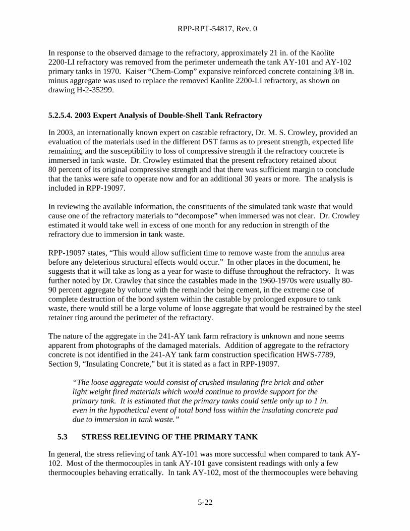
RPP-RPT-54817, Rev. 0
In response to the observed damage to the refractory, approximately 21 in. of the Kaolite 2200-LI refractory was removed from the perimeter underneath the tank AY-101 and AY-102 primary tanks in 1970. Kaiser “Chem-Comp” expansive reinforced concrete containing 3/8 in. minus aggregate was used to replace the removed Kaolite 2200-LI refractory, as shown on drawing H-2-35299.
5.2.5.4. 2003 Expert Analysis of Double-Shell Tank Refractory
In 2003, an internationally known expert on castable refractory, Dr. M. S. Crowley, provided an evaluation of the materials used in the different DST farms as to present strength, expected life remaining, and the susceptibility to loss of compressive strength if the refractory concrete is immersed in tank waste. Dr. Crowley estimated that the present refractory retained about 80 percent of its original compressive strength and that there was sufficient margin to conclude that the tanks were safe to operate now and for an additional 30 years or more. The analysis is included in RPP-19097. In reviewing the available information, the constituents of the simulated tank waste that would cause one of the refractory materials to “decompose” when immersed was not clear. Dr. Crowley estimated it would take well in excess of one month for any reduction in strength of the refractory due to immersion in tank waste. RPP-19097 states, “This would allow sufficient time to remove waste from the annulus area before any deleterious structural effects would occur.” In other places in the document, he suggests that it will take as long as a year for waste to diffuse throughout the refractory. It was further noted by Dr. Crawley that since the castables made in the 1960-1970s were usually 80-90 percent aggregate by volume with the remainder being cement, in the extreme case of complete destruction of the bond system within the castable by prolonged exposure to tank waste, there would still be a large volume of loose aggregate that would be restrained by the steel retainer ring around the perimeter of the refractory. The nature of the aggregate in the 241-AY tank farm refractory is unknown and none seems apparent from photographs of the damaged materials. Addition of aggregate to the refractory concrete is not identified in the 241-AY tank farm construction specification HWS-7789, Section 9, “Insulating Concrete,” but it is stated as a fact in RPP-19097.
“The loose aggregate would consist of crushed insulating fire brick and other light weight fired materials which would continue to provide support for the primary tank. It is estimated that the primary tanks could settle only up to 1 in. even in the hypothetical event of total bond loss within the insulating concrete pad due to immersion in tank waste.”
5.3 STRESS RELIEVING OF THE PRIMARY TANK
In general, the stress relieving of tank AY-101 was more successful when compared to tank AY-102. Most of the thermocouples in tank AY-101 gave consistent readings with only a few thermocouples behaving erratically. In tank AY-102, most of the thermocouples were behaving
5-22

RPP-RPT-54817, Rev. 0
erratically or not operational at all, with only a few giving consistent temperature data. As a result, stress relieving data from tank AY-101 is assumed to be more reliable than the data collected from tank AY-102. However, equipment difficulties along with non-ideal heat input and holding temperatures warrant noting. On November 1, 1969, during the controlled heating period to achieve the final holding temperature of 1100°F ±50°F, an equipment difficulty occurred at 9:00 a.m. This event was described in a letter (RPP-ASMT-53794, Section 1.2) on February 2, 1970, written by W.C. Armstrong, and reads as follows:
“At approximately 9:00 [a.m.] one burner stopped firing due to low gas pressure caused by icing up of the propane storage tanks. The ice was washed off the tanks and enough vapor pressure was obtained to fire both burners but there was not enough pressure to provide adequate flow to increase the firing rate. A temperature of approximately 900°F maximum was maintained until 4:30 p.m. 11/2/69 when steam was applied to the propane tanks. This increased the line pressure to 40 psi, well over that required for full firing.”
In the same letter, the following two paragraphs describe challenges with reaching the ideal holding temperature and an electrical equipment failure. They read as follows:
“At 9:00 p.m. all base temperatures were over 1000°F and dome temperatures were 1030°F and 1115°F. There was little temperature increase after 10:00 p.m., 11/2/69. A heat transfer equilibrium seemed to have been reached. At 12:00 a.m., a burner cut off because of electrical control difficulties. The dome temperature dropped by 30°F before re-ignition while the other surfaces of the tank were barely affected. As with Tank 102-AY, it was decided to invoke the ASME Code Sec. VIII rules for 1000°F holding temperature. The holding period was concluded at 1:20 a.m. 11/3/69. Controlled cooling was maintained at a rate of approximately 50°F per hour. The non-critical 600°F was reached at 11:00 a.m. 11/3/69.”
As with tank AY-102, the equipment configuration and conditions did not allow for stress relief to the desired temperature of 1100°F ± 50°F. Instead, a longer duration hold of 3 hours at the reduced temperature of 1000°F was deemed allowable. In the case of tank AY-101, this decision was made after the tank minimum had already been above 1000°F or just over 4 hours as they tried to increase to the 1100°F goal. Controlled cooling commenced and the tank was then deemed successfully stress relieved as described in the last paragraph of the W.C. Armstrong letter (RPP-ASMT-53794, Section 1.2) stating:
“Although the specification requirement of holding the tanks at 1100°F ± 50°F for one hour was not met, the holding of the tanks at 1000°F min for three hours is in full agreement with the provisions of the ASME Boiler and Pressure Vessel Code and assures positive post-weld stress relief to combat stress corrosion cracking.”
A similar note of successful stress relief was discovered in an inter-office memorandum from G. Kligfield to J. M. Frame (Appendix C, App Figure C-1), which reads as follows:
5-23

RPP-RPT-54817, Rev. 0
“It is with a sigh of relief and a feeling of pride in our Vitro team efforts over this past weekend that the following is noted: I feel that the help of our people during the weekend test period and the assist to PDM given prior to light-off, contributed immeasurably to the successful stress relief operation.”
5.4 TANK BOTTOM FLATNESS
Specification HWS-7789 specified that primary tank bottoms and secondary liner bottoms could have no root to crown slopes7 (bulges) greater than 3/8 in. per ft. and a maximum root to crown height measuring 2 in. or less, except that one bulge with a root to crown height measuring 3 in. may exist in each tank bottom. Issues with tank bottom flatness in tank AY-101 are discussed in the following sub-sections.
Secondary Liner Bottom Flatness 5.4.1
While there were fewer issues with tank bottom flatness in tank AY-101 compared to tank AY-102, there were still instances of tank bottom bulging in the secondary liner of tank AY-101. On 1/31/1969, the QA log entry states the following:
“Work continued on welding the butt seams on the upper side of tank AY-101[secondary] bottom. An unusually distorted area of the bottom was cut apart and prepared for re-welding. The weld was cut for approximately 4 feet in each direction from the intersections of seams AC and AD with seam U.”
Excessive distortion was experienced in the flat sections of the plates during the fabrication of 1/4 in. lower knuckle plates for the secondary liner of tank AY-101. Complete avoidance of thermally caused distortion is nearly impossible in butt-welded steel plate as thin as 1/4 in. The degree of distortion was noted to be directly proportional to the number and magnitude of weld repairs (RPP-ASMT-53793).
Tank AY-101 had a total of six instances of tank bottom bulging as compared to tank AY-102 with 22 instances of bottom bulging. In HES QA Reports (1969) (RPP-ASMT-53794, Section 1.13), a QA checklist dated 3/27/1969 states that a survey of the secondary tank bottom on 3/10/1969 found six places in tank AY-101 exceeding the 2 in. tolerance. One instance has a peak to valley tolerance of 3 in. and slope exceeds 3/8 in. /ft. These conditions were accepted on 3/11/1969. An example of a warped secondary liner can be seen in Figure 5-10.
7 May also be referred to as distortions, and peak to valley slopes.
5-24

RPP-RPT-54817, Rev. 0
Figure 5-10. Example of Warped Secondary Liner Bottom Knuckle (Photo – 8074)
Primary Tank Bottom Flatness 5.4.2
While no bottom flatness issues were noted for the tank AY-101 primary bottom, no QA daily logbooks between 5/20/1969 and 7/9/1969 could be located. It is during this time period that the primary tank bottom for tank AY-101 would have been constructed. The only available evidence describing the condition of the tank AY-101 primary bottom is a QA weekly checklist from July 10, 1969, which indicates that no problems existed, and photographs taken during refractory repairs described in Section 5.2. This checklist has been included in Appendix C as App Figure C-6. Figure 5-5 shows a refractory section that has been chipped out and void space between the primary tank bottom and refractory is apparent. It is possible that these void spaces are the result of bulging in the primary tank, which could cause unsupported areas of the primary bottom, deemed to be a contributing factor to primary tank failure in RPP-ASMT-53793.
Tank AY-101 Bottom Flatness Issues Summary 5.4.3
Tank AY-101 had out-of-tolerance bulging in the secondary liner bottom attributed to the thin (1/4 in.) plate material used in secondary liner construction and repeated weld repair. The secondary liner bulging in tank AY-101 was accepted as is. The principal issue with unsupported bulges in the secondary liner is flattening under the compressive load of a filled primary tank. The refractory may then crack due to its lack of strength in shear, leaving portions of the primary bottom unsupported. No QA daily logbooks between 5/20/1969 and 7/9/1969 could be located. This was the time period when the primary tank bottom for tank AY-101 would have been constructed. One QA weekly checklist indicated that the primary bottom in tank AY-101 met tank bottom flatness specifications. Despite this, photos from refractory repair after stress relief indicate that some voids existed between the primary tank and refractory surface. These voids could be attributed to primary tank bottom bulges, which would indicate unsupported areas of the primary tank exist in tank AY-101. This lack of support was identified as a contributing factor to primary tank failure in tank AY-102.
5-25

RPP-RPT-54817, Rev. 0
6.0 CONCLUSIONS
The leak assessment report for tank AY-102, RPP-ASMT-53793, identified first-of-a-kind construction difficulties and trial-and-error repairs as major contributing factors in the failure of that tank. To determine if improvements in DST construction continued, a review and evaluation of the construction records for tank AY-101 was completed to determine if similar or other difficulties were present. After a review of the construction history of tank AY-101, it is concluded that, during construction, similar issues occurred as did in tank AY-102, albeit to a lesser degree. Table 6-1 includes a summary of the issues seen in tank AY-101 as compared to tank AY-102, focusing on the critical difficulties that were identified in RPP-ASMT-53793. The most significant deficiency found in the review was the degradation and subsequent repair of the refractory in tanks AY-101 and AY-102. Both refractories were exposed to similar conditions of moisture and freezing temperatures during the curing stage, which is believed to have contributed to the friable nature and reduced vertical compressive strength. The refractory repairs required 21 in. of the periphery refractory to be chipped out and replaced with Portland cement. Welding improved with fabrication of tank AY-101 with a weld rejection of 10.2%. Regarding tank bottom flatness, tank AY-101 had a total of six instances of secondary liner bottom bulging as compared to tank AY-102 with 22 instances. While no QA daily logbooks were discovered for the period of time where the primary tank bottom was constructed, a discovered QA weekly inspection sheet did not indicate that bulging of the primary tank bottom occurred in tank AY-101 and substantiates that it met specification. Despite this, photos from refractory repair after stress relief indicate that voids existed between the primary tank and refractory surface. These voids could be attributed to primary tank bottom bulges, which would indicate that unsupported areas of the primary tank exist in tank AY-101. These unsupported areas were identified as a contributing factor to primary tank failure in tank AY-102. The stress relieving of tank AY-101 was more successful when compared to tank AY-102. Most of the thermocouples in tank AY-101 gave consistent readings with only a few thermocouples behaving erratically. In tank AY-102, most of the thermocouples were behaving erratically or not operational at all, with only a few giving consistent temperature data. As a result, stress relieving data from tank AY-101 is assumed to be more reliable than the data collected from tank AY-102. Tank AY-101 was stress relieved at 1000°F for 4 hours, which did not meet the specification of 1100°F ± 50°F for 1 hour. This reduced temperature, longer duration, stress relief method was deemed to be an acceptable alternative per provisions of the ASME Boiler and Pressure Vessel Code, which indicated that it would still produce a suitable stress relief and resistance to stress corrosion cracking. In conclusion, in the 241-AY tank farm, the first DST tank farm constructed, some improvement was seen in the construction of tank AY-101 following tank AY-102. Many of the same construction issues experienced in tank AY-102 also occurred in tank AY-101. The most significant deficiency found in the review was the degradation and repair of the refractory, which
6-1

RPP-RPT-54817, Rev. 0
was exposed to similar conditions of moisture and freezing temperatures during the curing stage. These conditions are believed to have contributed to the friable nature and reduced vertical compressive strength. Welding improved with fabrication of tank AY-101 with a lower weld rejection rate. Tank AY-101 had fewer instances of secondary liner bottom bulging as compared to tank AY-102. While there were no documented deficiencies on the QA checklists, photographic evidence does indicate the presence of void space between the primary tank bottom and refractory in tank AY-101. Unsupported areas of the primary tank bottom can contribute to primary tank failure. Stress relieving of tank AY-101 was more successful when compared to tank AY-102, but still had two noted equipment failures and required a reduced temperature, longer duration alternative to achieve acceptance.
Table 6-1. Summary Comparison of Tank AY-101 Construction to Tank AY-102 Tank AY-102 AY-101
Evaluation Document
RPP-ASMT-53793, Tank 241-AY-102 Leak Assessment Report
RPP-RPT-54817, Tank 241-AY-101 Tank Farm Construction Extent of Condition Review for Tank Integrity
Construction Order 1 2
Construction Contractor Pittsburgh-Des Moines (PDM) Steel Company
Secondary Bottom Material 0.25 in. plate, ASTM A515, Gr 60
Secondary Liner Bottom Bulges
Excessive distortion and bulges noted throughout. Maximum slope noted as much as 1 inch per foot. 22 places exceed 2 inch peak-to-valley tolerance.
Excessive distortion and bulges noted throughout. Maximum slope noted as much as 1 inch per foot. 6 places exceed 2 inch peak-to- valley tolerance.
Primary Bottom Material 0.375 in. plate, ASTM 515, Gr 60
Primary Bottom Weld Rework
33.8% 10.2%
Ultimately all welds were accepted and stress relieved, although problems with that process were noted.
Ultimately all welds were accepted and stress relieved.
Primary Liner Bottom Bulges
Primary bottom flatness described as “generally good,” however, during refractory repair, much of the primary tank bottom wasn’t in contact with the refractory. Voids were filled with Styrofoam .
Primary bottom flatness described as “generally good,” however, during refractory repair, much of the primary tank bottom wasn’t in contact with the refractory. Voids were filled with Styrofoam.
6-2

RPP-RPT-54817, Rev. 0
Tank AY-102 AY-101
Stress Relieving Process
Required days to remove all the water in the refractory and temperatures were as low as 915°F (~1000°F) for the 3 hour hold, 5 days of heating total.
Modifications made to reduce TC spread, 3 hour time requirement met, total time just over 2 days, plus overnight hold to dry refractory. Held 3 hours above 1000°F.
Refractory Kaolite 2200LI
Refractory Protection Poor - often allowed to saturate with rain water, not protected from freezing.
Refractory Condition
After hydro test refractory found to be very degraded, extensively cracked and spalled. Samples showed excessive carbonation.
Refractory Repair Major- 21 in. of perimeter removed and replaced with reinforced structural concrete.
Overall Conclusion on Construction Difficulties
Difficultly with liner fabrication and the castable refractory left the tank with unsupported areas in the tank bottom and unexpected residual stresses in the tank bottom that probably contributed to failure.
With the second DST built, some issues were improved (lower weld rework rate, less secondary bulges, improved heat treatment). The refractory degradation was still severe and required major repairs. Less instances of an unsupported primary bottom are expected.
6-3

RPP-RPT-54817, Rev. 0
7.0 REFERENCES
API-936, 2008, Refractory Installation Quality Control – Inspection and Testing Monolithic Refractory Linings and Materials, American Petroleum Institute, Washington, D.C.
ARH-1833, 1970, Investigation of the 241-AY Insulating Refractory Task Force Report, Atlantic
Richfield Hanford Company, Richland, Washington. ARH-205, 1967, Design Criteria Purex AY Tank Farm, Atlantic Richfield Hanford Company,
Richland Washington. ASME, 1965 Edition, Boiler and Pressure Vessel, American Society of Mechanical Engineers,
New York, New York. BNWL-B-56, 1971, Evaluation of Kaolite-2000 Insulating Castable, (RPP-19097,
Attachment 7), Battelle Memorial Institute, Pacific Northwest Laboratory, Richland, Washington.
Centre of Environmental Science-Section Substances and Products [CML-SSP] Working Paper
2001.002, 2001, Literature Study on Degradation Products of Known Emissions, Leiden University, Leidin, Netherlands.
Choi, S; Crosson, G.; Mueller, K. T.; Seraphin, S.; and Chorover, J., 2005, “Clay mineral weathering and contaminant dynamics in a caustic aqueous system II. Mineral transformation and Microscale Partitioning,” Geochimica et Cosmochimica Acta, Vol. 69, No. 18, pp. 4437–4451, http://cals.arizona.edu/swes/chorover_lab/pdf_papers/Choi_et_al_2005b.pdf.
HWS-7789, 1968, Specification for Primary and Secondary Steel Tanks Purex Tank Farm
Expansion Project IAP-614 Revision 2, Vitro Hanford Engineering Services, Richland Washington.
HWS-7790, 1968, Specifications for Excavation and Tank Foundations Purex Tank Farm
Expansion Revision 1, Vitro Hanford Engineering Services, Richland, Washington. HWS-7791, 1968, Specifications for Side Walls and Dome Nuclear Waste Storage Tank Project
IAP-614 Purex Tank Farm Expansion Revision 1, Vitro Hanford Engineering Services, Richland, Washington.
HWS-7792, 1968, Specification for Completion of 241-AY Purex Tank Farm Expansion Project
IAP-614 Revision 1, Vitro Hanford Engineering Services, Richland, Washington. H-14-010506, 2012, Dome Penetration Schedules (WST/WSTA) Tank 241-AY-101, Sheet 1
Revision 18, Washington River Protection Solutions LLC, Richland, Washington. H-14-010506, 2010, Dome Penetration Schedules (WST/WSTA) Tank 241-AY-101, Sheet 2
Revision 2, Washington River Protection Solutions LLC, Richland, Washington.
7-1

RPP-RPT-54817, Rev. 0
H-2-35299, 1970, Structural Modification Insulating Concrete Plan & Details, Vitro Hanford Engineering Services, Richland, Washington.
H-2-64306, 1968, Tank Foundation Plan, Vitro Hanford Engineering Services, Richland,
Washington. H-2-64307, 1968, Structural Insulating Concrete Plan and Details, Vitro Hanford Engineering
Services, Richland, Washington. H-2-64310, 1968, Concrete Tank Section and Details, Vitro Hanford Engineering Services,
Richland, Washington.
H-2-64449, 1968, Tank Elevation and Details, Vitro Hanford Engineering Services, Richland, Washington.
OE-03-0009, 2003, Operability Evaluation for AZ-102 Primary Tank Leak Detection Systems, CH2M HILL Hanford Group, Inc., Richland, Washington.
PER-2003-3066, 2003, “AZ-102 UT Discovers Concrete Insulation Pad Degraded,” CH2M HILL Hanford Group, Inc., Richland, Washington.
PNNL-14706, 2004, DST Primary Tank Settlement Evaluation, Pacific Northwest National Laboratory, Richland, Washington.
PNNL-21836, 2012, Characteristics of STP Pre-2004 Archived KE Basin Sludge Samples Before and After Re-Jarring in the RPL – April 2012, Pacific Northwest National Laboratory, Richland, Washington.
RHO-C-17, 1978, Additional Analyses of Underground Waste Storage Tanks 241-AW, Rockwell Hanford Operations, Richland, Washington.
Routschka, G., 2008, Pocket Manual Refractory Materials, Third Edition, McGraw-Hill Companies, Columbus, Ohio.
RPP-19097, 2003, Evaluation of Insulating Concrete in Hanford Double Shell Tanks, CH2MHILL Hanford Group, Inc., Richland, Washington.
RPP-ASMT-53793, 2012, Tank 241-AY-102 Leak Assessment Report, Washington River Protection Solutions LLC, Richland, Washington.
RPP-ASMT-53794, 2012, Tank 241-AY-102 Leak Assessment Supporting Documentation: Miscellaneous Reports, Letters, Memoranda, and Data, Washington River Protection Solutions LLC, Richland, Washington.
WRPS-1204931, 2012, Double-Shell Tank 241-AY-102 Primary Tank Leak Extent of Condition Evaluation and Recommended Annulus Visual Inspection Intervals. Washington River Protection Solutions LLC, Richland, Washington
7-2

RPP-RPT-54817, Rev. 0
241-AY-101 Tank Log Book Key Event Table Appendix A
A-1

RPP-RPT-54817, Rev. 0
Reference Date Comment Event Type8
1. 7/15/1968 Excavation and grading taking place for site preparation. CM
2. 9/16/1968
The contractor set the form and reinforcing steel for the leak detection well of the tank AY-101, and encasement leak detection well. The form was checked out dimensionally and found to be correct.
CM
3. 9/18/1968 All the tank AY-101 drain pipe was set above the ditch previously dug for it. CM
4. 9/19/1968 Layout was started on the tank AY-101 foundation. CM
5. 9/23/1968 Installation of drain pipe and leak detection well for tank AY-101 was completed. CM
6. 9/30/1968
The concrete foundation for tank AY-101 was poured to the satisfaction of Jack Diehl, Vitro/HES inspector. Primary loading of 4000 pounds and initial loading of 17,000 pounds was made on the soil bearing test platform.
CM
7. 10/14/1968 Removing forms from tank AY-102 foundation and setting them up for tank AY-101. CM
8. 10/16/1968
Monroe Berry and Ralph Nederhood supervised the installation of the remaining thermocouples in tank 101. Work continued on removing blockouts from tank AY-102 foundation to move them to tank AY-101.
CM
9. 10/18/1968 Rod busters laid re-steel for tank AY-101 foundation. CM
10. 10/21/1968
Rod busters completed installation of re-steel on tank AY-101 foundation at noon and left the area. Grout Inc. then immediately started installing wooden blockouts for drains slots in tank AY-101. Work was also started on installation of circular angle for tank AY-101.
CM
11. 10/22/1968 Work continued on installing the 1 1/2 inch circular angle, and the blockouts for the drain slots, on tank AY-101 foundation. CM
12. 10/23/1968
Re-steel checked out after the carpenters completed the installation of blockouts for drain slots on tank AY-101. Paul Pritchard and Verne Dobbs checked all blockouts, and 1 1/2 by 1 1/2 inch angle and set them all to +/- 1/8". The contractor placed a layer of gravel on road way all around the perimeter of tank AY-101.
CM
13. 10/24/1968
Concrete pour for tank AY-101. Started at 7:05 a.m. and ended at 1:00 p.m. Total yardage was 300.5 cu. Yards. The majority of the concrete was of good except for approximately 6 loads that were observed to be wet. It was found to be difficult to control since the top of the aggregate pile was dry and lower in the pile was wet. Efforts were made to dry the material to get as consistent a mix as possible.
CM / CI
8 CM: General Construction Milestone, CI: Construction Issue
A-2

RPP-RPT-54817, Rev. 0
Reference Date Comment Event Type8
14. 10/25/1968
The contractor started stripping out the blockouts. The concrete was still too green and it broke the edges too much so the work was stopped until after it has been water cured. Water curing started.
CM / CI
15. 10/28/1968 A continuous flow of water was being maintained into the formed area of tank AY-101. CM
16. 11/4/1968 Removed all forms from around the foundation of tank AY-101. Wood blockouts for drain slots were removed with a minimum amount of damage to the adjacent concrete.
CM
17. 11/5/1968 Work was started laying the 20 inch wide bearing plate, and repairing of damaged concrete from blockout removal CM
18. 11/6/1968
Work was completed on installation of 20 inch wide bearing plate for tank AY-101. All concrete repairs were finished, drain slots were cleaned out for both tanks, and the areas around both foundations were leveled with a bulldozer.
CM
19. 11/7/1968 Remove twelve nails embedded in the edge of the tank AY-101 foundation and to backfill around the edges of each foundation up to the 622.50 foot elevation.
CM
20. 11/14/1968
Ten 3/8" plates for the primary tank bottoms had been taken into the shop and had been milled on their long sides for weld-joint geometry without orienting the mill-stenciled side of the plate in proper relation to the joint. There are 5 of the 10 plates where the mill stenciling will be on the inside surface of one primary tank. Plan was developed by Al Shot to weld over the stencils of the improperly oriented plates and grind them smooth (after transferring the mill stencil information to the other side of the plate). With two subsequent stress-relief cycles, it was assumed that the quality of the plate would not be undermined.
CM / CI
21. 11/15/1968 Work was completed today in forming the 1/4" plates for secondary tanks. Work was started today cutting and beveling the 7/8" plates for the primary tank knuckles.
CM
22. 11/19/1968 Loading of a truck with 1/4" plate for secondary liner bottom of AY-101 began this afternoon. CM
23. 11/20/1968 The truck carrying the bottom plates for tank AY-101 had left for Richland, Washington shortly after 5:00 P.M. last evening. CM
24. 11/21/1968
1st truck load of secondary tank plates arrived & unloaded. Discussed the requirement of a plywood cover for the tank foundation. A verbal request of H. Stein for a temporary opening in the secondary tank wall.
CM
25. 12/2/1968 Secondary bottom plates for tank AY-101 will be shipped tonight or tomorrow morning from Provo. CM
A-3

RPP-RPT-54817, Rev. 0
Reference Date Comment Event Type8
26. 12/3/1968
Al Short and PDM quality control man checking the heat numbers of the bottom plates for tank AY-101 (secondary). Attempted to flame straighten a section on 101 secondary bottom and noted 2-1/2 in. out of flatness, but it was unsuccessful. An attempt to straighten it in the hydraulic press was equally unsuccessful. Mr. Disk De Jong asked if inspector had any objection to tack-welding the edge of the plate to an I beam and shipping it that way. Inspector told him that even though he did not particularly like the condition it was in at the time, he could not object to the 2 1/2" out of flatness until the bottom had been completely welded, so he consented to his shipping the plate.
CI
27. 12/4/1968 Waiting on knuckle plates from Provo. Expect load of bottom plates for tank 101 tomorrow. CM
28. 12/6/1968 Repair welding of sec. knuckle plates for tank AY-101 continued. CM
29. 12/6/1968 Plates for tank 101 secondary bottom arrived on job site. Center plate fabricated for tank 101 is being used for tank 102. CM
30. 12/7/1968 All eight secondary tank knuckle plate sub-sections were stress relieved according to the approved procedure. CM
31. 12/9/1968
The eight sections of secondary tank knuckle plates were removed from the stress relief furnace and taken to the hydraulic press for straightening. After straighten, they were placed in the fabricated jig for rechecking. They were also checked for dimensions. Unloading, straightening, and checking occupied the entire day.
CM
32. 12/9/1968 The knuckle plates are back in the shop for some minor straightening. CM
33. 12/10/1968 Weld repair continued on the knuckle plates for tank 101 (secondary). CM / CI
34. 12/11/1968 Weld repair of the 8 knuckle sections of the AY-101 secondary tank. CM / CI
35. 12/12/1968
Work continued on repairing defective welding of the secondary knuckle plates of tank AY-101, x-raying those repairs, cutting more primary tank knuckles, rolling them, forming them, beveling them, fitting them, and tacking them together. Secondary tank AY-101 knuckles - 2 sections ready for stress relief. 79 repairs remaining on the other 24 welds
CM / CI
36. 12/13/1968 Cutting of additional 7/8" plates for primary tank knuckles, manual welding on 7/8" sections, and mainly repairing and x-raying repairs on 1/4" secondary tank knuckles.
CM / CI
37. 12/13/1968 One truck load of knuckle plates arrived and unloaded. Also, on the truck were several pieces of primary bottom plates. CM
38. 12/14/1968 5 sections completely repaired and ready for stress relief. In the remaining 3 sections records show 21 repairs remaining. CM
39. 12/16/1968 What few repairs remained on the tank AY-101 secondary plates were completed and x-rayed. The x-rays were reviewed and approved.
CM
A-4

RPP-RPT-54817, Rev. 0
Reference Date Comment Event Type8
40. 12/16/1968
PDM contractor placed knuckle plates in position on the tank. Having some difficulty in fit-up due to the warpage in the knuckle plates. Production welding has not started. The center plate for tank AY-101 secondary has been removed from the job site.
CM / CI
41. 12/17/1968 Secondary knuckle fabrication completed for tank AY-101, noted as somewhat better quality than tank AY-102. CM
42. 12/18/1968 The remainder of the secondary tank knuckle plates were checked out and loaded on a truck for shipment to the work site. CM
43. 12/20/1968 Contractor continued to ready bottom secondary plates for welding. Manual welding was completed yesterday on 8 knuckle places.
CM
44. 12/24/1968 Start was made on tank AY-101 knuckle plate welding. CM
45. 12/26/1968 Tank AY-101 bottom knuckle sections welded. CM
46. 12/27/1968 Tank AY-101 bottom plates fitted to knuckles. CM
47. 12/30/1968 Several inches of snowfall during past weekend. CI
48. 12/31/1968 Additional snow overnight & during day. CI
49. 1/7/1969 Bottom secondary plates of tank AY-101 are being assembled and clipped preparatory to welding. CM
50. 1/9/1969 Production welding started on knuckle to bottom plates on tank 101 secondary liner. CM
51. 1/10/1969 Welding was continued on top side of AY-101 secondary liner bottom seams 2, 3, and 4. CM
52. 1/16/1969 Cleanup of snow and ice started on tank AY-101 secondary liner bottom. CI
53. 1/20/1969 Welding beams 6 & 8 on tank AY-101 (top side). CM
54. 1/28/1969 All 8 primary tank knuckle sections (BP-13) for tank AY-101, were being stress relieved today and are scheduled for shipment tomorrow.
CM
55. 1/29/1969 No welding was performed on either tank today. Tank 101 was covered with snow. The craftsmen shoveled snow of tk. 101 until noon, and were sent home.
CI
56. 1/30/1969 The snow was cleaned off the 101 tank bottom, and after properly preheating, manual welding was initiated. CM / CI
57. 1/30/1969 Started working on tank AY-101 secondary bottom. Welding remaining seams. CM
58. 1/31/1969
Work continued on welding the butt seams on the upper side of tank AY-101 bottom. An unusually distorted area of the bottom was cut apart and prepared for re-welding. The weld was cut for approximately 4 feet in each direction from the intersections of seams AC and AD with seam U.
CM
59. 1/31/1969 Continued working on tank AY-101 secondary bottom and raised 1st shell course and placed in position. CM
A-5

RPP-RPT-54817, Rev. 0
Reference Date Comment Event Type8
60. 2/3/1969 The first course of shell plates had been installed on tank AY-101 on Friday, and two welders worked on them all day today, fitting them, and welding 3 of the vertical seams.
CM
61. 2/3/1969 Welding first shell course tank AY-101 secondary liner. CM
62. 2/4/1969 All vertical seams of the first course shell plate on tank AY-101 were completed. CM
63. 2/4/1969 Continued welding 1st shell course tank 101. CM
64. 2/5/1969 Work was started on removal of lifting beams from tank 102 and transferring them to tank 101. Welding continued on inside of shell to knuckle joint of tank AY-101.
CM
65. 2/5/1969 Started transfer of lifting beams from TK 102 to TK 101 CM
66. 2/6/1969 Welding continued on knuckle shell joint, and lifting beams were moved from tank AY-102 to tank AY-101. CM
67. 2/6/1969 Snow & ice still on ground. Continued transferring lifting beams from tank AY-102 to tank AY-101. Checked and recorded mill numbers on plates (1st shell course tank AY-101 secondary)
CM / CI
68. 2/7/1969 Lifting beams were fastened to tank AY-101 bottom, and preparations were made to lift the tank on Monday. CM
69. 2/7/1969 Lifted tank AY-101 secondary off the foundation. Ice on foundation hindering work to some extent. CM / CI
70. 2/10/1969
At least 2 inches of water and ice covering the tank foundation. The 2" x 10" planks on which the tank bottoms had initially been supported were completely submerged, and frozen into the ice. Tank lifting was impeded by these weather conditions, and after four hours of effort the tank was only 6 inches above the foundation. An examination of the interior and exterior surfaces of the tank at 11:30 AM failed to detect any damage to any portion of the tank as a result of lifting. Raising of the tank continued the remainder of the day. Water from melting snow kept the tank AY-101 foundation covered, and drainage was difficult because of the frozen soil.
CI
71. 2/11/1969
Lifting of the tank 101 continued all day, requiring constant checking for distortion. None was detected. Because of the frozen condition of the ground, absorption is slow, and the presence of excessive water is beginning to be of concern.
CM / CI
72. 2/11/1969 Snow and ice still on ground. Raising tank 101 off foundation. Ice on foundation hampers work. Contractor has been very careful in raising tank bottom AY-101 to working level.
CM / CI
73. 2/12/1969
Tank AY-101 was raised and supported, so that work was begun on completing the inside of knuckle plate to first shell course weld. Work was also initiated on arc-gouging the weld joints on the lower surface of the bottom. Immediately after lunch, one of the PDM welders almost quit the job because there was so much ice and water under the tank.
CM / CI
A-6

RPP-RPT-54817, Rev. 0
Reference Date Comment Event Type8
74. 2/12/1969
Some snow & ice still on ground. Tank AY-101 secondary shell raised and additional cribs are being installed under the center of tank. Ice is still on tank foundation causing difficulty in finding good bracing for cribs.
CM / CI
75. 2/13/1969
Work continued on arc-gauging the lower sides of the bottom weld joints, and two welders were welding the same joint after grinding. Ice was removed from the drain slots, and shoveled outside the tank area. Preheating of the base metal prior to welding was required at first, but discontinued when the temperature rose above 32 degrees.
CM / CI
76. 2/14/1969
Scarfing of all the weld joints on the lower side of the bottom continued throughout the morning, and was completed in the early afternoon. I crawled under the tank in the afternoon and inspected the arc-gouged joints, both before and after grinding, and found them to be in excellent condition. The completed welding had not been brushed yet, but it appears to be of superior quality to the welding on tank AY-102.
CM
77. 2/14/1969
Scarfing and welding in progress on bottom side of secondary liner. Ice still on foundation. Welding is being completed on several knuckle plates. Preparation being made to perform x-ray work over weekend.
CM / CI
78. 2/24/1969
Approx. 1" snow during weekend. Contractor cleaning off snow. Radiography films read. Repair of weld defects in progress. Cleanup of tank foundation in progress. Measured circumference of tank 6" inches above the seam H1 - 251.54' @ 38 degrees.
CI
79. 2/25/1969
Final x-rays shot in repairs to tank bottom between x-ray work on bottom plate seams and knuckle seams. Cleaned concrete foundation, installed insulation in center ring, and flushed out drains. Tank bottom visually inspected, all repair work completed. All work satisfactory. Started lowering tank at approximately 1:30 p.m.
CM
80. 2/26/1969
Continued lowering tank to foundation (3:00PM). Checked clearance of center ring with concrete foundation. No bind could be detected. X-ray work has been performed on all knuckle to shell seams (H1).
CM
81. 2/27/1969
Removing lifting beams from tank. Plate repairs in progress (clips, etc) started placement of 3/8" slide plate and skirt on concrete bearing plate. Checked placement of graphite and noted position of chamfer.
CM
82. 2/28/1969
Continued to repair damages to shell plate caused by clips. Continued installing slip plate installed yesterday. Had raised 3/8" off of concrete bearing plate due to variation in temperature. Soap tested all of secondary bottom plate seams and the straight sections of knuckle plate seams except for approx. 1" of one knuckle plate seam which had too much warp in the seam to accept the testing equipment. No leaks noted.
CM / CI
83. 3/2/1969 X-ray in progress on tank 101 secondary shell to bottom knuckle plate seams. CM
A-7

RPP-RPT-54817, Rev. 0
Reference Date Comment Event Type8
84. 3/3/1969
Continued installing slide plate on concrete bearing plate and skirt to secondary tank liner. Liberal amount of graphite installed under slide plate. Requested contractor place protection over edge of slide plate to prevent debris from entering beneath plate. Continued installing reinforcing ring near top of 1st shell course. Getting 2nd shell course plates ready to install. Cut 8" x 12" hole in 1st shell course 16'9" C.W. from seam K7 and 14" above seam H1.
CM
85. 3/4/1969
Continued installing reinforcing ring on first course of tank AY-101 secondary. Continued installing skid plate & skirt around secondary liner bottom. Requested again that skid plate be protected from debris. Started installing 2nd course secondary liner shell on tank AY-101. All plates installed and manual welding started on vertical seams.
CM
86. 3/5/1969
Continued welding vert. seams of 2nd shell course. Attempted to qualify operators of horizontal automatic welding machine on test plates attached to the shell wall. This proved not successful as the operator could not see the back side of the weld by use of mirrors and test plate was welded to tank shell. Contractor then proceeded to qualify operators on the tank shell seam. Welding appeared to be very satisfactory but is to be x-rayed for proof.
CM / CI
87. 3/6/1969
Completed automatic welding of secondary liner seam H-2. Radiograph of test section of seam indicates weld is acceptable. This qualifies the operator - Hugo Stein for performing this automatic welding. This also qualifies the procedure 60-26A. Continued the following welding: reinforcing ring to 1st shell course; studs to angle attached to skirt & concrete slide plate; skirt ring completed.
CM
88. 3/7/1969
Started installing reinforcing angle on 2nd shell course. Air piping and repairs to shell exterior (clips, etc.) continued. Enlarged 8" x 12" access holes to 30" diameter access holes in both tanks for personnel use.
CM / CI
89. 3/12/1969 Crew setting forms in tank AY-101 for Kaolite placement. Installed protective cover on tank CM
90. 3/17/1969
Outside temp 54 degrees F. PDM - started placing Kaolite insulation at 9:30 AM using 15 1/2 gal water / 5-40# bags of kaolite. Inside temp of tank was 60 degrees F. Water/ratio of mix was satisfactory. Section 5 - sample taken at 10:30 AM of material after the material was vibrated in place. Section 9 - sample taken at 2:30 PM after material was vibrated in place. Inside tank temp 70 degrees F. Completed at 3:45 PM. Form work for section 1 was moved from section 5.
CM
91. 3/18/1969
Temp inside tank at 9:15 a.m. was 63 degrees F. Started placing Kaolite insulation in section 13 at 9:15 a.m. and completed at 11:45 a.m. Started section 4 at 12:30 p.m. and completed at 3:05 p.m. Started section 7 at 3:10 p.m. and completed at 6:00 p.m. Started sec 17 at 6:00 p.m. and completed at 8:10 p.m. Samples taken of all sections placed. Two slight hairline cracks have appeared in section 13. Using 15 1/2 gal water / 5-40# bags of mix. Mix appeared to be acceptable.
CM
A-8

RPP-RPT-54817, Rev. 0
Reference Date Comment Event Type8
92. 3/19/1969
Temperature inside tank AY-101 at 9:20 a.m. was 68 degrees F. Started placing Kaolite insulation in section 3 at 8:15 a.m. using 15 1/2 gal / batch mix. Sample taken at 9:20 AM. Section completed at 11:00 a.m. Started section 8 at 11:00 a.m. Sample taken at 1:45 p.m. Temperature inside the tank was 86 degrees F. Section 8 completed at 2:20 p.m. Started section 21 at 2:25 p.m. Sample taken 4:45 p.m. Completed section 21 at 5:10 p.m.. Started section 2 at 5:20 p.m. using 15 3/4 gal / batch mix. The warm day had further removed moisture from the bags of Kaolite material. Sample taken section 2 at 7:40 p.m. Temperature was 60 degrees. Section 2 completed at 7:45 p.m. Started section 11 at 7:45 p.m. Sample taken at 9:15 p.m. Temperature was 48 degrees F. Completed section at 10:25 p.m. All samples taken were from materials vibrated in place.
CM
93. 3/20/1969
Started placing Kaolite insulation in section 15 at 8:50 a.m. using 15 1/2 gal / batch. Difficulty was experienced with placing material due to dryness. At 9:30 a.m., mix was changed to 15 3/4 gal / batch. Sample taken at 10:30 a.m. Temperature inside tank AY-101 at 10:30 a.m. was 72 degrees F. Completed section 15 at 1:30 pm. Started section 12 at 11:40 a.m. Sample taken at 1:30 p.m. Temperature in tank was 85 degrees F. Completed section 12 at 3:15 p.m. Start section 25 at 3:20 p.m. Samples section 25 at 5:25 p.m. Temperature in tank was 74 degrees F. Completed section 25 at 6:10 p.m. Started section 19 at 6:10 p.m. Sampled section 6 at 11:30 p.m. Temp in tank was 58 degrees. Completed section 6 at 11:50 p.m. All batches from 9:50 p.m. on used 15 3/4 gal. Mr. Trumball from B&W visited the jobsite. Discussion on mix, mixing time, placing, density and thermal characteristics were made during his visit.
CM
94. 3/21/1969
Started placing Kaolite insulation in section 16 at 9:00 a.m. Sample taken at 10:20 a.m. Temperature at 11:00 a.m. was 68 degrees F. Completed section 16 at 11:45 a.m. Started section 29 at 11:45 a.m. Sample taken at 2:00 p.m. Temperature inside tank at 2:00 p.m. was 81 degrees F. Sample slightly dry. Humidity inside tank very high and very warm. Completed section at 11:45 a.m. Started section 23 at 3:40 p.m. Sample taken at 3:50 p.m. Temperature at 11:00 was 80 degrees F. Completed section 23 at 6:30 p.m. Started section 20 at 6:35 p.m. Sample taken at 9:45 p.m. One batch too wet made contractor remove from form. This delayed completion of section unil10:45 p.m. Temperature at time of sample was 60 degrees F. All batches except one mentioned above used 15 3/4 gal water.
CM
95. 3/22/1969
Over the weekend the protective covering was ripped off the tank and the Kaolite insulation was exposed to the weather for the rest of the weekend. It is surmised that the covering was ripped off last Saturday afternoon after all sections placed had at least 18 hours of satisfactory curing period. The insulation was subjected to low temp. of 26 degrees on Sunday night. At this point no detectable damage is evident to the insulation placed to date.
CI
A-9

RPP-RPT-54817, Rev. 0
Reference Date Comment Event Type8
96. 3/24/1969
Started section 10 at 9:30 a.m. (Kaolite insulation) Sample taken at 11:00 a.m. Temperature was 55 degrees F. Completed section 16 at noon. Started section 24 at 1:30 p.m. Sample taken at 2:00 p.m. Temperature at 2:00 p.m. was 58 degrees F. Completed section at 3:30 p.m. Started section 33 at 3:40 p.m. Sample taken at 5:30 p.m. Temperature 52 degrees F. Completed section at 6:00 p.m. Started section 27 at 6:00 p.m. Sample taken at 7:50 p.m. Temperature 44 degrees F. Completed section at 9:10 p.m. Started section 14 at 9:10 p.m. Sample taken at 10:40 p.m. Temp 38 degrees F. Completed section @ midnight. All batches used 15 3/4 gal of water. Protective covering was partially restored over the section of tank requiring the placement of Kaolite insulation.
CM / CI
97. 3/25/1969
Started placing Kaolite insulation in section 28 at 8:45 a.m. Sample taken at 11:00 a.m. Completed section 28 at 11:45 a.m. Started section 36 at 11:50 a.m. Sample taken at 2:30 p.m. Temperature was 70 degrees F. Completed section 36 at 3:40 p.m. Started section 18 at 3:45 p.m. Sample taken at 5:50 p.m. Temperature was 64 degrees F. Completed section at 6:15 p.m. Started section 32 at 6:25 p.m. Sample taken at 9:00 p.m. Temperature was 42 degrees F. Completed section 32 at 9:20 p.m. Started section 31 at 9:25 p.m. Sample taken @ 11:15 p.m. Completed section 31 at midnight.
CM
98. 3/26/1969
Started section 22 at 8:35 a.m. Temperature inside tank was 54 degrees F. Sampled Kaolite insulation 9:45 a.m. Completed section at 11:00 a.m. Started placing Kaolite insulation in section 26 at 11:10 a.m. Temperature was 62 degrees F. Sampled taken at 1:00 p.m. Temperature was 70 degrees F. Completed section 26 at 2:45 p.m. Started placing Kaolite insulation in section 30 at 2:50 p.m. Sampled taken at 4:10 p.m. Temperature was 68 degrees F. Completed section 30 at 5:10 p.m. Started section 35 at 5:15 p.m. Sampled taken at 7:40 p.m. Temperature was 58 degrees F. Completed section at 7:50 p.m. Started placing Kaolite insulation in section 34 at 7:50 p.m. Sampled taken at 9:45 p.m. Temperature was 56 degrees F. All above placed using 15 3/4 gal / batch. Completed section 34 at 10:30 p.m. This completes placement of Kaolite insulation in tank 101. Repairs will be necessary. Elevation checks will be made tomorrow.
CM / CI
99. 4/2/1969 Continued installing & fitting primary shell & knuckle plates. CM
100. 4/7/1969 Considerable rainfall fell over the weekend with 3-4 inches water in secondary tank on the outside of the Kaolite insulation. CI
101. 4/18/1969
The 1st 10 foot 6" section on the concrete wall was placed in 5 lifts. Concrete was started at 8:20 a.m. and completed by 2:35 p.m. Concrete slump was very consistently between 2 1/2" and 3". Pour was made using squeeze-crete equipment. No unusual incidents. Three sample cylinders made - (no. 1 - 1st 2' lift; no. 2 - 3rd 2' lift; no. 3 - 5th 2' lift). Total yards placed - 150.
CM
A-10

RPP-RPT-54817, Rev. 0
Reference Date Comment Event Type8
102. 4/25/1969
Placed concrete in the second lift around the secondary shell of tank AY-101. Due to difficulty with placement equipment (squeeze-crete) there is a possibility of having a cold joint between the 1st and 2nd 2' lift around the tank. A crane and bucket was utilized in an effort to prevent cold joint. Some rock pockets may appear since concrete was dropped too far. The latter half of the pour was completed without further incident. Slump of concrete varied between 2 1/2 " to 3". Test cylinders were taken on the 2nd, 4th & 5th lifts. Pour was started at 8:20 a.m. and completed by 3:30 p.m. Total yards - 147.
CM
103. 4/30/1969
An investigation was made for cold joints and rock pockets in concrete pour made on 4/25/69 on tank AY-101. There are no cold joints apparent. Several minor rock pockets were exposed to view. These were repaired satisfactorily. The concrete appears to be acceptable.
CM / CI
104. 5/2/1969
The third lift of concrete wall around the tank AY-101 secondary shell was placed. Pour was started @ 8:15 and completed at 2 PM. Approximately 20 minutes in time was lost during the pour due to failure of the squeeze-crete equipment. Concrete was placed in satisfactory manner. Test cylinders were made as follows - (1 - 2nd 2' lift; 2 - 3rd 2' lift; 3 - 4th 2' lift). Slump varied between 3" & 3 1/2".
CM
105. 5/20/1969 Backfill continued from 18' to 25' level. Backfill & compaction work continues satisfactory. CM
106. 7/9/1969 Welders continued to weld on other verticals on SR-2 course (2nd course) in tank AY-101. CM
107. 7/10/1969
Surveyed elevations of 65 locations on the bottom of tank AY-101 primary. Continued to weld the vertical joints of SR-2 on tank AY-101. The E4 joint was arc-gouged on the inside, forced back out into the proper radial curvature, and re-welded.
CM
108. 7/11/1969 Finished the SR-2 verticals in tank AY-101 and welded a manual closure pass in the BA-3 joint of tank AY-101. Inspected and noted areas for repair on SR-2 welds.
CM
109. 7/14/1969 Inspection of welds on shell plates. CM
110. 7/15/1969
At approximately 1:40 PM, smoke was seen emitting from the north side of tank AY-101. A small fire was burning in the bottom of the annulus of tank AY-101. Al Short entered the annulus on the south side and made his way to the location of the fire. Stein was there and had the fire essentially extinguished with a dry chemical extinguisher. I found that a piece of tarpaulin had been folded and left lying in the bottom of the annulus. Arc-gouging on the outside of the BA-3 joint had ignited the tarpaulin. In a short time, all pieces of the tarp had been removed from the tank and thoroughly wet with water.
CI
111. 7/16/1969 Automatic welding on the outside of the tank AY-101 primary BA-3 joint continued with two weld passes nearly completed. CM
A-11

RPP-RPT-54817, Rev. 0
Reference Date Comment Event Type8
112. 7/16/1969
All efforts were concentrated on completing the automatic welding on the outside of the BA-3 joint. The final pass was completed about 2:08 p.m. with P. Metcalf inspecting immediately behind the welding machine and a welder following immediately behind Metcalf repairing the areas marked for repair.
CM
113. 7/18/1969
Checked all the beveled lower edges of the eight SR-3 plates for cleanliness and found them to be in good shape. The upper edge of the SR-2 course had been ground to clean metal and painted with deoxaluminate. Erecting of the SR-3 course started at approx. 10:00 a.m. and was not quite completed when the men quit for the day.
CM
114. 7/21/1969 Fitting up of verticals, manual welding, and PD-MATIC welding of SR-3 verticals continued in tank AY-101 primary. CM
115. 7/22/1969 Discontinued using the PD-MATIC welder on the tank AY-101 primary SR-3 vertical joints, and welded on the remaining joints manually.
CM / CI
116. 7/24/1969 Inspection of welds and weld repair. CM
117. 7/25/1969 Inspection of a small area of BA-4 weld occurred and appeared satisfactory. CM
118. 7/28/1969 On tank AY-101, a second weld pass was almost completed on the outside of the BA-4 joint. CM
119. 7/29/1969 BA-4 weld joint and visual inspection complete and ready for radiography. CM
120. 7/30/1969 Welding equipment removed from inside of primary tank. CM
121. 8/6/1969 Shell Plates for SR-4 course were staged. CM
122. 8/8/1969 SR-4 course shell plates erected and verticals fit together and welding was initiated. Began fabrication of temporary dome supports.
CM
123. 8/11/1969 75% of BA-5 joint was fit together, and welding initiated. CM
124. 8/18/1969 BA-5 weld joint completed and ready for radiography. CM
125. 8/19/1969 Inspection of tank bottom. “There appears to be more plate damage to the bottom plates in this tank than in tank 101.” CI
126. 8/20/1969 PDM discovered that their layout location for dome supports was incorrect. Layout was started over. CI
127. 8/25/1969 Almost entire bottom was magnafluxed, and upper knuckle plates were all erected. CM
128. 8/26/1969 Vertical weld joints in upper knuckles were fit and tacked. CM
129. 8/27/1969 Center dome support was set. CM
130. 9/2/1969 Closure joint on knuckle plates was trimmed fit and welded. CM
131. 9/4/1969 All temporary dome supports in place. CM
132. 9/17/1969 Five dome segments installed on vessel, fit, tack-welded, and welding initiated. CM
A-12

RPP-RPT-54817, Rev. 0
Reference Date Comment Event Type8
133. 10/2/1969 Final dome segment installed. CM
134. 10/3/1969 In fitting the joint between the dome plate and the knuckle, so much stress had been imposed to close the joint that the knuckle plate was actually pulled flat.
CI
135. 10/6/1969 Initiated layout of penetrations. CM
136. 10/13/1969 Dome Center plate installed. CM
137. 10/15/1969 Started installation of insulation for stress relieving. CM
138. 10/17/1969 Vacuum testing of the primary bottom was successfully completed. CM
139. 10/24/1969 Cleaned, repaired, and mag fluxed bottom of primary tank. CM
140. 10/27/1969 Insulation complete. Burners for stress relief set in place. CM
141. 10/28/1969 Installed thermocouples and connected propane piping. CM
142. 10/29/1969 Attempt to start stress relieving prevented by PDM recorder motor burning up. CI
143. 10/31/1969 Stress relief began at 7:30 p.m. CM
144. 11/1/1969
Max temperatures of 600 F maintained in order to facilitate drying of the kaolite. When it appeared the kaolite had dried considerably, temps were raised to 800 F and held through the night.
CM
145. 11/2/1969
Cold temps caused low pressure in propane line. Max temps remained near 900F. Steam was used on the propane lines in the afternoon to increase pressure and complete stress relief. Burners were off at 12:10 a.m.
CI/CM
146. 11/3/1969 Recorders turned off at 11:00 a.m. CM
147. 11/5/1969 Began removal of insulation. CM
148. 11/6/1969 Filling tank with water for hydrostatic testing. CM
149. 11/10/1969 Tank water fill completed by 2:00 p.m. welds were covered with blue chalk. CM
150. 11/11/1969 Hydro test completed and acceptable by 2:00 p.m. CM
151. 11/12/1969 Secondary knuckles were erected, fit together, and welding initiated. Water from hydro test was being pumped out. CM
152. 11/18/1969 All water removed that was possible. Last knuckle section fit in place, trimmed, and welding initiated. CM
153. 12/1/1969 Started erecting reinforcing steel for concrete shell. CM
154. 12/8/1969 Started to set concrete forms. CM
155. 12/11/1969 Poured concrete up to 9 feet past the knuckle. CM
156. 12/15/1969 Removed concrete forms and completed erection of reinforcing steel. CM
157. 12/17/1969 Poured dome concrete. CM
158. 12/24/1969 Started to dismantle temporary dome supports. CM
159. 1/6/1970 Began removing some of the temporary support structures. CM
A-13

RPP-RPT-54817, Rev. 0
Reference Date Comment Event Type8
160. 1/7/1970 Began removal of vertical dome supports. CM
161. 1/22/1970 A routine RM check revealed that some of the new construction area was contaminated. CI
162. 1/24/1970
A radiation monitoring unit determined the extent of contamination spread indications pointed to a spread into the interior of tank AY-101. Clean up commenced and work re-started.
CI
163. 1/27/1970 Back fill commenced around the tank. Start of construction completion. CM
164. 2/3/1970
Final inspection of tank AY-101 interior. One thermowell was found to have only four holding clamps instead of five. Everything else was acceptable except for five areas of slight damage to the tank bottom.
CM / CI
165. 2/6/1970 Previously mentioned damaged tank bottom areas deemed too minor for concern. CI
166. 5/20/1970 Checking tank AY-101 annulus. CM
167. 5/21/1970 Meeting of ARHCO, BNW, and Vitro employees regarding the condition of the kaolite insulating concrete in both tanks. CI
168. 6/30/1970
Note: The following log entry pertains to tank AY-102. Kaolite removal disclosed areas the inner tank bottom had pulled up from the kaolite as much as 1-1.5". It was decided to preserve the void by gluing insulating foam such as Styrofoam covering the volume of the void. The foam could later erode or melt as weight and heat were added.
CI
169. 7/15/1970 Hung lights in tank AY-101 and started removing steel retainer ring for refractory repair. CI
170. 7/21/1970
Inspection of tank AY-101 Kaolite, and lunch discussion of why it is cracking and deteriorating. Started sawing refractory sections in the tank, but not removing material. The same degree of punky deterioration of material does not exist as in tank AY-102. Tank 101 had punky material generally less than .5" to 0 or .125" where in 102 generally was .75 to 1" or more. Relevant comments from meeting notes from this day: Several months after pours, when stress relief being made, considerable steam was observed to rise and it was found to be quite difficult to bring relieving temperature above the 180 degree to 210 degree Fahrenheit area. Question raised if steam occurring through a lengthy period be due to very limited circulation to the atmosphere? No answer. Cracks in the castable will cause expansion. Ring walls in structural concrete will cause breaks in hot temperature. The steel band held most of the cracks from breaking out loose. The cracks may come from steel expansion, especially where warpage occurs at the tank knuckle and tank moves outward. Generally, it is agreed that neither the primary nor the secondary tank bottom is flat.
CI
A-14

RPP-RPT-54817, Rev. 0
Reference Date Comment Event Type8
171. 7/22/1970 Removing material for first pour in tank AY-101. CI
172. 7/28/1970 Poured 10 sections in second third of tank AY-101. Had some difficulty working concrete back in afternoon. CI
173. 8/3/1970 Laborers removing last third of periphery Kaolite using chain saws and chipping guns. Concrete forms set. CI
174. 8/4/1970 Final concrete pour completes perimeter concrete ring tank support. CI
175. 8/11/1970 Final check of annulus areas for cleanliness and alignment of leak detection probes in tank AY-101 accepted. CM
A-15

RPP-RPT-54817, Rev. 0
241-AY-101 Weld Maps Appendix B
B-1

RPP-RPT-54817, Rev. 0
App Figure B-1. Tank AY-101 Primary Tank Bottom Weld Map
B-2

RPP-RPT-54817, Rev. 0
App Figure B-2. Tank AY-101 Secondary Bottom Weld Map
B-3

RPP-RPT-54817, Rev. 0
App Figure B-3. Tank AY-101 Primary Shell Weld Map
B-4

RPP-RPT-54817, Rev. 0
App Figure B-4. Tank AY-101 Secondary Shell Weld Map
B-5

RPP-RPT-54817, Rev. 0
Tank Deficiency Documentation Appendix C
C-1

RPP-RPT-54817, Rev. 0
App Figure C-1. Memo from G. Kligfield (Dated 11/5/1969)
C-2

RPP-RPT-54817, Rev. 0
App Figure C-2. Kaolite Change Request Letter (Dated 9/4/1968)
C-3

RPP-RPT-54817, Rev. 0
App Figure C-3. Kaolite Record of Design Change (Dated 10/2/1968)
C-4
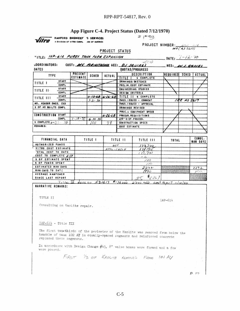
RPP-RPT-54817, Rev. 0
App Figure C-4. Project Status (Dated 7/12/1970)
C-5

RPP-RPT-54817, Rev. 0
App Figure C-5. Project Status (Dated 7/26/1970)
C-6
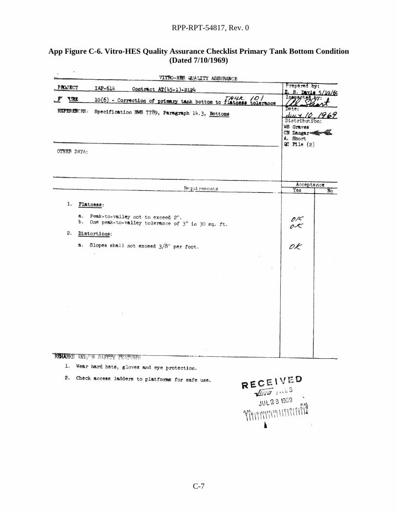
RPP-RPT-54817, Rev. 0
App Figure C-6. Vitro-HES Quality Assurance Checklist Primary Tank Bottom Condition (Dated 7/10/1969)
C-7