Embed Size (px)
Citation preview

ES24 2.4M Nomadic AntennaAll designs, specifications, and availabilities of products and services presented in this bulletin are subject to change without notice. (0512A)
© 2012 ASC Signal Corporation
2.4 Meter Nomadic
The reflector is available in one-, three-, and nine-piece carbon fiber modular panels with latches for quick assembly
Vehicle mount version with desert tan finish
The ASC Signal 2.4 m Nomadic is a highly flexible antenna system designed to operate on almost any satcom band and in many configurations. The entire reflector structure consists of lightweight carbon fiber panels, with multiple mounting scenarios, and can be ordered in motorized or non-motorized versions. With feeds available to address L-, C-, X-, Ku-, K-, Ka-, and Q-bands, as well as low PIM capable feeds, few applications are beyond its capabilities.
This antenna supports a variety of interchangeable feeds which are engineered for simple removal and replacement in the field. The reflector is constructed with a precision-formed honeycomb core and a carbon fiber skin which assures durability and high performance. The reflector is readily available in one-, three-, and nine-piece versions - all sharing common RF design components and performance capabilities.
The Nomadic is designed to be lightweight, with maximum stiffness, yet offers compact and highly robust components. The versatile architecture makes it ideal for launching highly divergent equipment applications using a single, flexible, modular and cost-effective equipment base.
Electronically engineered to operate at multiple frequencies, ASC Signal’s 2.4 meter Nomadic is capable of transmitting and receiving signals under demanding wind loads and surviving winds up to 100 mph. Weighing less than 220 kg (480 lb), in fully motorized versions (including feeds), the tactical version can be deployed by two trained individuals within 30 minutes.
FEATURES • Multiple Versions available
- One-, three-, and nine-piece reflector panels
- Motorized and non-motorized axes
- Pedestal, Tactical and Mobile Mounts
• Six or Ten-case ISO shippable version
• Lightweight reflector , high accuracy tracking mount
• Interchangeable feed systems for quick field swaps
• Meets all applicable FCC, ITU and Mil-Spec standards
• Designed to comply with MIL-STD-810F
• Various trailer configurations are available
• Low PIM X-band available

ES24 2.4M Nomadic AntennaAll designs, specifications, and availabilities of products and services presented in this bulletin are subject to change without notice. (0512A)
© 2012 ASC Signal Corporation
2.4 Meter NomadicThe 2.4M Nomadic is designed around a base configuration to provide modular flexibility and configurability. In addition, it is designed to be rugged and to allow for maximum compactability to withstand the demands and rigors of transport in military and commercial aircraft. The feeds are also palletized to allow for easy transport and for band changes in minutes.
ELECTRICALC-band X-band Ku-band K-band Ka-band Q-band
Tx Gain (typ. Midband) 41.3 43.6 48.2 51.0 55.3 58.0Rx Gain (typ. Midband) 37.6 43.3 47.3 47.4 52.0 52.1G/T (typ. Midband)1 18.3 23.8 26.5 26.5 28.8 28.8EIRP (Max Theoretical) - - - - - -3dB Beamwidth Rx 2.09 1.23 0.79 0.76 0.44 0.401 G/T shown is typical for mid-band single thread, nominal temperature rated LNA connected directly to the feed flange and does not include post LNA contributions. See Feed sheets for more details
ENVIRONMENTALOperating Conditions (Typical)Pointing Accuracy(Degrees RMS) Typical (RMS) 4 GHz 7.75 GHz 12 GHz 20 GHz
Calm 0.18 0.22 0.19 0.19
Winds 30 gusting 45 mph 0.19 0.24 0.21 0.24
Typical (Peak)Calm 0.27 0.30 0.26 0.29
Winds 30 gusting 45 mph 0.29 0.35 0.43 0.80Survival 100 mph ballasted 125 mph stowed
Temperatures Operational SurvivalRange -40°C to 60°C (-40°F to 140°F) -58°C to 71°C (-50°F to 160°F)
Seismic 1G Vertical and Horizontal; 8.3 Richter, 11 Mercalli
Solar Radiation 360 BTU/h/ft2 (1135 watts/m 2)
Rain Up to 10 cm/h (4 in/h)
Relative Humidity 0% to 100%Shock & Vibration As encounterd by Air, Ship, Rail, and TruckAtmospheric As encountered in moderately corrosive coastal and industrial
environments
Altitude Operational SurvivalUp to 12,000 ft Up to 40,000 ft
MECHANICALReflector Multi-Band InterchangeableColor White (other colors available)Material Carbon FiberSegments One, Three, and Nine Segment VersionsController Type Multi Axis Tracking Controller with Auto Acquisition
Prime Power Indoor 110-220 VAC 50/60 Hz (Universal)Outdoor 24 VDC, 120 VAC (Field Configurable)
Power Consumption 20A or less @ 24VDC, 5A @ 120VAC (est.)Motor (Az, El, and Pol) 24 VDCFeed Type Prime Focus, OffsetMount Type El over Az Pedestal
Angle Transducers 19 bit optical encoder
Angle Resolution 0.0010
Positioning Accuracy 0.0050 (est.)Limit Switch optionalBoom/Positioner Capacity
Size Limit 38” x 14” x 12” (96cm x 36cm x 30cm) BoomWeight Limit 220 pounds; Boom 300 pounds; Positioner
Overall Dimensions (stow) 131” L 86”W 24”HStow Height <24 inches
Azimuth Elevation Polarization
±150° Continuous 0° to 90° of Boresight ±100°
Maximum Travel Limits User defineable within mechanical limits
Operate Limits Hardware & Software Settable
Remote IDU Interconnect Ethernet & RS232/422Remote Interface Remote Operation Software, SNMP V1 & V2cIDU/ODU IFL Single Mode Fiber Optic Cable
Optional Sensors GPS, Compass, and Inclinometers
Controller Package Single Box Outdoor Motor Controller3RU 19” EIA Rack Mounted Indoor Controller

ES24 2.4M Nomadic AntennaAll designs, specifications, and availabilities of products and services presented in this bulletin are subject to change without notice. (0512A)
© 2012 ASC Signal Corporation
2.4 Meter Nomadic- Mobile, Vehicle Mount
Section F-F
3.2
3.0
1.6
F
F
EL AXIS
ODU COVER
86.0
36.5
32.617.9
13.9
113.5
112.9
131.4
Reflector Rotation Radius
Boom Rotation Radius
Boom Equipment Mounting
Look Angle 0
Azimuth Axis
R 107.4
CGR 110.1
Deployed to 0 Elevation
18.85
Elevation Axis
Azimuth AxisCenter of Gravity (CG) Stow Position
18.53.0
9.0
14.5
23.9
20.3
110.4
130.5
°
°
°
All dimensions are in inches
All dimensions are in inches
All dimensions are in inches
ASC offers a wide variety of carriage based feeds from for drop-in, on-the-fly mission changes.

ES24 2.4M Nomadic AntennaAll designs, specifications, and availabilities of products and services presented in this bulletin are subject to change without notice. (0512A)
© 2012 ASC Signal Corporation
2.4 Meter Nomadic
°
Ø
Ø
- Rugged Quick Deploy
Reflector Rotation Radius
Boom Rotation Radius
Center of Gravity (CG)
Azimuth Axis
R 115.8
R 97.2
45.5
52.3
149.6
17.7
All dimensions are in inches
°
Elevation Axis
R 117.1Boom Rotation Radius
Azimuth Axis
132.7
96.0
All dimensions are in inches
All dimensions are in inches
Forward
Mounting Hole Pattern
Locating Pin Hole
Section A-AScale 1:2
10.500
22.125
23.000
0.875 Slip FitØ
Ø
Ø
12x 0.406 Wide Slot
24.000
30
Ø
1511PL
Complete setup time with two technicians in under an hour. Feed swap outs in under 10 mintes
ES24 2.4M Nomadic AntennaAll designs, specifications, and availabilities of products and services presented in this bulletin are subject to change without notice. (0512A)
© 2012 ASC Signal Corporation
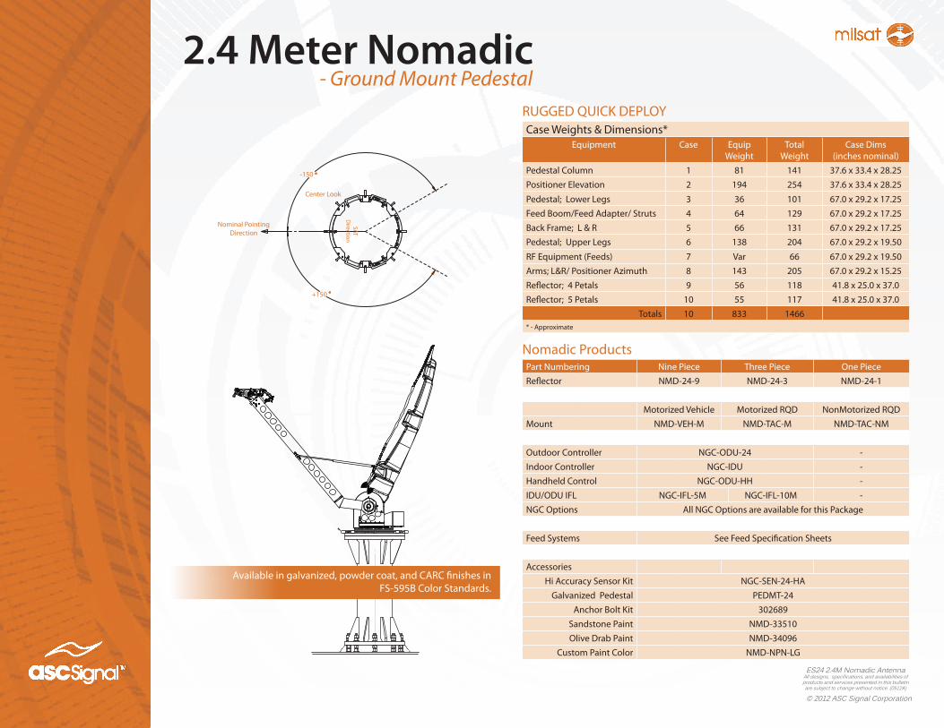
2.4 Meter NomadicRUGGED QUICK DEPLOYCase Weights & Dimensions*
Equipment Case Equip Weight
Total Weight
Case Dims(inches nominal)
Pedestal Column 1 81 141 37.6 x 33.4 x 28.25Positioner Elevation 2 194 254 37.6 x 33.4 x 28.25
Pedestal; Lower Legs 3 36 101 67.0 x 29.2 x 17.25Feed Boom/Feed Adapter/ Struts 4 64 129 67.0 x 29.2 x 17.25Back Frame; L & R 5 66 131 67.0 x 29.2 x 17.25Pedestal; Upper Legs 6 138 204 67.0 x 29.2 x 19.50
RF Equipment (Feeds) 7 Var 66 67.0 x 29.2 x 19.50Arms; L&R/ Positioner Azimuth 8 143 205 67.0 x 29.2 x 15.25Reflector; 4 Petals 9 56 118 41.8 x 25.0 x 37.0Reflector; 5 Petals 10 55 117 41.8 x 25.0 x 37.0
Totals 10 833 1466* - Approximate
Nomadic ProductsPart Numbering Nine Piece Three Piece One PieceReflector NMD-24-9 NMD-24-3 NMD-24-1
Motorized Vehicle Motorized RQD NonMotorized RQDMount NMD-VEH-M NMD-TAC-M NMD-TAC-NM
Outdoor Controller NGC-ODU-24 -Indoor Controller NGC-IDU -Handheld Control NGC-ODU-HH -IDU/ODU IFL NGC-IFL-5M NGC-IFL-10M -NGC Options All NGC Options are available for this Package
Feed Systems See Feed Specification Sheets
AccessoriesHi Accuracy Sensor Kit NGC-SEN-24-HA
Galvanized Pedestal PEDMT-24Anchor Bolt Kit 302689
Sandstone Paint NMD-33510Olive Drab Paint NMD-34096
Custom Paint Color NMD-NPN-LG
- Ground Mount Pedestal
°
°
-150
+150
Nominal Pointing Direction
SATD
irection
Center Look
Available in galvanized, powder coat, and CARC finishes in FS-595B Color Standards.

ES24 2.4M Nomadic AntennaAll designs, specifications, and availabilities of
products and services presented in this bulletin are subject to change without notice. (0512A)
www.ascsignal.com
+1-214-291-7654
O F F I C E S • U n i t e d S t a t e s • C a n a d a • B r a z i l • S p a i n • U n i t e d K i n g d o m • F r a n c e • G e r m a n y • S o u t h A f r i c a • I n d i a • C h i n a • M a l a y s i a