Embed Size (px)
Citation preview

22nd EuroForth Conference
September 15-17, 2006
Cambridge, England


3
Preface
EuroForth is an annual conference on the Forth programming language, stackmachines, and related topics, and has been held since 1985. The 22nd Euro-Forth finds us in Cambridge for the first time. The two previous EuroForthswere held in Schloss Dagstuhl, Germany (2004) and in Santander, Spain(2005). Information on earlier conferences can be found at the EuroForthhome page (http://dec.bournemouth.ac.uk/forth/euro/index.html).
Since 1994, EuroForth has a refereed and a non-refereed track.For the refereed track, six papers were submitted (a new record), and
three were accepted (50% acceptance rate). Each paper was sent to threeprogram committee members for review. A total of nineteen reviews wasproduced for the six papers. This year, none of the program committeemembers has submitted a paper. I thank the authors for their papers, andthe reviewers for their often extensive reviews.
Five papers and abstracts were submitted to the non-refereed track intime to be included in these proceedings. Workshops and social events com-plement the program.
We are grateful to Janet Nelson for organizing this year’s EuroForth.
Anton Ertl
Program committee
Sergey N. Baranov, Motorola ZAO, Russia (secondary chair)M. Anton Ertl, TU Wien (chair)David Gregg, University of Dublin, Trinity CollegeUlrich Hoffmann, Heidelberger Druckmaschinen AGPhil Koopman, Carnegie Mellon UniversityJaanus Poial, Estonian Information Technology College, TallinnBradford Rodriguez, T-Recursive TechnologyReuben Thomas

4
Contents
Refereed Papers
Paul Frenger: Fifteen Years of Forth Publishing with ACM . . . . . . . . . . . . . . 5Mark Shannon, Chris Bailey: Register Allocation for Stack Machines . . . 13Jamel Tayeb, Smail Niar: Adapting the EPIC Register Stack for an EfficientExecution of Forth . . . . . . . . . . . . . . . . . . . . . . . . . . . . . . . . . . . . . . . . . . . . . . . . . . . . . 21
Non-refereed papers
Angel Robert Lynas, Bill Stoddart: Adding Lambda Expressions to Forth 27Jaanus Poial: Typing Tools for Typeless Stack Languages . . . . . . . . . . . . . . 40M. Anton Ertl: A Portable C Function Call Interface . . . . . . . . . . . . . . . . . . . 47N.J. Nelson: The Nearly Invisible Database or ForthQL . . . . . . . . . . . . . . . . 52K.B.Swiatlowski: Database access for illiterate programmers . . . . . . . . . . . . 58David Guzeman: A 21st Century Sea Change Taking Place in EmbeddedMicroprocessors . . . . . . . . . . . . . . . . . . . . . . . . . . . . . . . . . . . . . . . . . . . . . . . . . . . . . . . . 64David Guzeman: Defining Processing Solutions for Mesh Computing Envi-ronments . . . . . . . . . . . . . . . . . . . . . . . . . . . . . . . . . . . . . . . . . . . . . . . . . . . . . . . . . . . . . . . 78
5
Fifteen Years of Forth Publishing with ACM
Paul Frenger M.D.
P.O. Box 820506
Houston, TX 77282-0506 USA
ABSTRACT
The author has written numerous Forth programming language articles for
various publications of the Association for Computing Machinery (ACM). These
principally include the SIGForth Newsletter (1989 Ð 1994) and Sigplan Notices
(1996 Ð 2006). These ACM journals also have included the work of several guest
authors writing about Forth. This paper discusses some of the highlights of this
fifteen-year epoch, which has informed a generation of computer professionals
about the Forth language.
1 SIGForth: a Partnership of Forth Professionals and the ACM
Last year marked an unusual event: fifteen years of professional Forth articles and papers
appearing in publications of the Association for Computing Machinery (ACM). From the
beginning, this pairing was unexpected: after all, the ACM (founded in 1947, with a current
membership near 80,000) is the world's oldest computing society [1]. Forth, on the other hand, is
supposedly an arcane, non-mainstream, seldom-used programming language. Its role has been
described [2]: ÒHardware engineers love Forth. Traditional computer scientists hate itÓ.
Within this relatively unfavorable context, in 1988 George W. Shaw II of California, convinced
ACM to let him and several friends create SIGForth (the special interest group for the Forth
programming language). The following year the new ACM SIGForth generated two significant
milestones: the first SIGForth Workshop and the SIGForth Newsletter.
At the first ACM SIGForth Workshop (Austin, Texas) presentations were given by Forth
authorities such as: Robert Davis, Gary Feierbach, Larry Forsley, Tom Hand, Rick Hoselton,
Howard Leverenz, Greg Lisle, Brian Mikiten, Leonard Morgenstern, Dietrich Neubert, George
Shaw, Virgil Stamps, Rick VanNorman, Jack Woehr and myself [3]. The 1990 Workshop was
held in Dallas and the 1991 meeting in San Antonio. Additional authors at these conferences
included: Warren Bean, Alan Furman, Charles Johnsen, Phil Koopman, John Orr, Frank Sergeant,
Paul Snow, John Wavrik, and others [4]. Chuck Moore spoke at the 1992 Workshop.
The SIGForth Newsletter would become a quarterly publication of about 32 pages, from Vol. 1,
Issue 1, April 1989, to Vol. 4, Issue 4, December 1994). I reported on the first two years of
SIGForth at the 1990 Rochester Forth Conference [5]. Later I described in detail what it was like
to put together a publication like the Newsletter [6].

6
SIGForth was located ÒvirtuallyÓ in Texas, providing the balancing point between the East and
West Coast Forth establishments. It leveraged Forth enthusiasts in the great middle of the US,
such as those in NASA (Houston) and the rapidly-forming ÒSilicon HillsÓ area (Austin).
2 Forth in SIGForth Newsletter: 1989 - 1994
To quote from my 1990 Rochester paper: ÒOne of the goals of the [SIGForth] Newsletter was to
set it apart from Forth Dimensions, an old and honored FIG publication. Many people have
commented on the high quality of that first Newsletter. This may largely be attributed to the
status of its contributors: Chuck Moore, George Shaw, Charles Curley, Alan Furman, C.H. Ting,
Charles Johnsen and Klaus Schleisiek-Kern (in Germany)Ó.
ACM SIGForth Newsletter, Volume 1, Issue 1 (Spring 1989) gave Forth inventor Moore his
ÒFORTHoughtÓ column, chairman Shaw his ÒWords from the ChairmanÓ section, and the
Newsletter editor (first Curley, later myself) a ÒForth EstateÓ column. Founders Furman, Ting,
Schleisiek-Kern and others contributed generously. A variety of issues and practices were
covered: Forth commercialization1, the F-PC compiler2, Forth in Europe3, custom Forth CPU
design4, Forth vendors5, the ACM SIGForth bylaws6, a summary of the first annual SIGForth
Workshop7, and the ANS Forth progress report8. The Newsletter was off to a great start.
I served as editor for the Newsletter after Charles CurleyÕs departure, completing Volume 1,
Issue 2 (Summer 1989), which Charles had begun. That issue contained the usual regular columns;
we also published several excellent articles: for9 and against10 using text files in Forth, explored
the cmForth metacompiler11, saw how to implement high-level exception handlers12, learned
about state space searches13, and derived a string-based Forth CASE statement14. We included a
book review for the Forth-like MINT programming language15.
Newsletter Volume 1, Issue 3 (Fall 1989) contained a Silicon Valley entrepreneurÕs tale16, an
RCA 1802 software simulator17 and notes on multiple-threaded vocabularies18. In Issue 4
(Winter 1989), the Holon system was reviewed19, the 1989 Rochester Forth Conference
summarized20, Forth stack frames described21, a new ÒdualsÓ data structure concept proposed22,
the Harris RTX-2001 processor reviewed23 and PocketForth for the Macintosh24.
1 Alan Furman, 5-6 2 C. H. Ting, 15-17 3 Klaus Schleisiek-Kern, 18 4 Charles Johnsen, 19-21 5 C. H. Ting and Charles Curley, 21-23 6 Brad Rodriguez and Charles Curley, 25-26 7 George Shaw, 27 8 George Shaw, 28-29 9 Tom Zimmer, 5 10 Brad Rodriguez, 6 11 Jay Melvin, 7-8 12 Brad Rodriguez, 11-13 13 Rick Hoselton, 14-17 14 Paul Frenger, 18-21 15 Paul Frenger, 19-22 16 Russell Fish, 23+27 17 Alberto Pasquale, 24-25 18 Harold M. Martin, 26-27 19 Wolf Wejgaard, 13-16 20 Larry Forsley, 17-18 21 Brad Rodriguez, 19-21 22 Rick Hoselton, 22-28 23 Paul Frenger, 31 24 Paul Frenger, 32

7
Volume 2, Issue 1 (Sept. 1990) dealt with Forth software licensing25, a table-driven AI string
matching system26, the 1990 Rochester Forth Conference27, a philosophy of Forth28, and an
RTX-2000 system review29. Issue 2 (Dec. 1990) explored the online GEnie Forth Roundtable30,
a Forth BNF parser31, and abstracts for the 1990 Rochester Forth Conference32. Issue 3 (March
1991) listed abstracts of the 1990 SIGForth Workshop33, told how a tethered Forth system was
developed34, showed a stack assembler language for a compiler course35, and described an RTX-
2000 arbitrary waveform generator36. Issue 4 (June 1991) included Forth programming tricks37, a
discussion of Forth compilation techniques38, and a novel single-instruction computer design39.
Volume 3, Issue 1 (Summer 1991) presented insights into Postscript40, showed a convenient way
to handle numbers41, discussed recursion and co-routines for B-trees42, further developed the
single-instruction computer43, described a programming system named for the mathematician
Leibniz44, and expounded on toys that can teach hardware and software interfacing45. Issue
2 (Fall 1991) was a special Postscript Issue. It contained a tutorial on Postscript46, described a
Forth system written in PostScript47, and reviewed PostScript Tutor software for the PC48. Issue
3 (Winter 1991) was a special Hardware issue. Significant articles included: a stack-oriented
multi-processor system called FLIP-FLOP49, the BERT robot50, distributing Forth51, random
variables in Forth52, and driving stepper motors from a parallel port53. Issue 4 (Spring 1992) was
a special Review issue. It contained guidance for loading text files from screen-based Forths54,
some humorous Forth proverbs55, a version of FIG-Forth for the Signetics 80C52256, the
obituary for Adm. Grace Murray Hopper57, some robots that teach Forth58, learning real-time
industrial programming59 and free-form number evaluation60. Reviews included: MI-SHELL, a
Forth-like MS/DOS shell61, the Plain English language62, UTIL for palm computers63, M-CODE
direct assembler for x86 CPU64, The Computer Journal magazine65, and a Forth Applications
book for the PC66.
25 Brad Rodriguez, 13-14 26 Paul Frenger, 15-18 27 Larry Forsley, 19-25 28 Jay Melvin, 31 29 Virgil Stamps, 32 30 Alan Furman, 7-8 31 Brad Rodriguez, 13-18 32 Larry Forsley, 19-25 33 Howard Harkness, 9-10 34 Harold M. Martin, 17-19 35 Gerald Wildenberg, 20-22 36 Paul Frenger, 27-31 37 Frank Sergeant, 7-8 38 Greg Lisle, 21-22 39 P. A. Laplante, 23-26 40 Paul Snow, 7-9 41 Paul Frenger, 10 42 Rick Hoselton, 11-16 43 P. A. Laplante, 21-22 44 Andreas Goppold, 23-24 45 Paul Frenger, 25-29 46 Don Lancaster, 15-19 47 Mitch Bradley, 20-24 48 Paul Frenger, 32 49 Peter Grabienski, 5-11 50 Karl Brown, 15-18 51 Frank Sergeant, 19-20 52 Matthew M. Burke, 21-24 53 Paul Frenger, 25-28 54 Brad Rodriguez, 5-6 55 Rick Hoselton, 7 56 Alberto Pasquale, 11-13 57 John Jeter, 13 58 C. Ronald Kube, 14-16 59 C. A. Maynard, 19-22 60 John R. Hayes, 28 61 Rick Hoselton, 7 62 Paul Frenger, 9-10 63 Royal Randall, 23 64 Paul Frenger, 25-26 65 Mike Foley, 27 66 Paul Frenger, 29-30

8
Volume 4, Issue 1 (Summer 1992) was a special Genie Forth Roundtable issue. Interactive
discussions with special guests took place on the Genie dial-up network and the transcripts were
later posted to the Newsletter. An introduction was provided by a Genie SysOp67; guests
included the public relations guru for FIG68, the editor of FIGÕs Forth Dimemsions magazine69,
the new SIGForth chairman70, a noted Forth author and instructor71, a Ford Motor Company
engineer72, and an ANS Forth Standards team member73. Other articles included Chuck MooreÕs
tribute to FIG-Forth74, A review of the 1992 Rochester Forth Conference75, a book review of
Scientific Forth76, and the Forth Successes Project report77. Issue 2 (Fall 1992) was a Forth
Internals issue. Topics discussed included the CREATE .. DOES> pair78, design of threaded
code interpreters79, syntax of user-defined local variables80, the Forth LATHE Engine concept81,
and JSR Forth for Amiga82. A review of the PIC 16C5x microcontroller was presented83. In the
news: the SIGForth executive committee bestowed the 1992 SIGForth STACK Award on
founder George Shaw, and the 1993 STACK Award on Newsletter editor Paul Frenger.
Issue 3 (December 1993) was the 1992 SIGForth Workshop Proceedings issue, part I. These
papers were presented: Forth on the Space Shuttle84, A first Forth course for engineers85,
construction of a Forth CPU86, and a C-to-Forth compiler87. Regular Newsletter articles were
represented by my discussion of desktop publishing88, a review of Yerkes Forth for the Mac89,
and a critical look at the ANS standardization process90. Issue 4 (December 1994) contained part
II of the 1992 SIGForth Workshop Proceedings. These papers were presented: a software-stack
data type91, Forth GUI design and MetaWINDOW92, ForthÕs role in mainstream computer
science courses93, and computer algebra in Forth94.
Reading these articles and papers by the first generation of Forth practitioners is awe-inspiring.
Some of this is preserved in the ACM Digital Library [7], but much material is out of print.
3 Forth in Sigplan Notices: 1996 to Today
The Forth Report appeared in Sigplan Notices on a frequent but irregular basis, in non-conference
issues which allowed columns and articles. I have chronologically summarized these forty-four
67 Gary Smith, 3-4 68 Jan Shepherd, 5-6 69 Marlin Ouverson, 8-10 70 Irving Montanez, 11-12 71 Michael Ham, 17-19 72 Len Zettel, 21-24 73 Ron Braithewaite, 27-30 74 Chuck Moore, 2 75 Irving Montanez, 20 76 Julian V. Noble, 31-32 77 Darrel Johansen, 13-14 78 Paul Thomas, 6-8 79 P. Joseph Hong, 11-16 80 John R. Hayes, 19-20 + 26 81 Paul Frenger, 21-23 82 Mike Haas, 24-26 83 Paul Frenger, 27-28 84 Robert T. Caffrey, et al, P1-P8 85 Frank N. DiMeo, P9-P11 86 Yong M. Lee and Edward Conjura, P12-P16 87 Alexander Sakharov, P17-P18 88 Paul Frenger, 4 + 32 89 Bob Loewenstein, 5-6 90 Michael L. Gassanenko, 27-31 91 Jon W. Osterlund, P19-P22 92 P. D. Lopez, P23-P27 93 Richard E. Haskell, P28-P34 94 Julian V. Noble, P35-P43

9
Forth Report columns and described them in detail [8, 9]; these reviews are available online to
subscribers via the ACM Portal. These articles fall into the following categories: object-oriented
Forths, conference reports, robotics, space applications, game construction, artificial intelligence,
Forth groups and personalities, Forth vendors, Forth techniques, and miscellaneous applications
and topics. They are briefly listed below.
Volume 31, Number 4 (April 1996) inaugurated the Forth Column in Sigplan Notices with two
guest columns 95, 96 on Object Oriented Forths. In Number 8 (August 1996) I reviewed the 1996
Rochester Forth Conference97. In Number 12 (December 1996) I listed a number of useful Forth
resources for Sigplan readers98.
In Volume 32, Number 2 (February 1997) our guest author described his Beetle Forth Virtual
Processor99. In Number 4 (April 1997) I discussed robotics programming languages100; with
Number 6 (June 1997) I focused attention on Forth as a robotics language101. Forth implemented
on single board computers102 was the topic for Number 11 (November 1997).
Volume 33, Number 2 (February 1998) contained my insights at the very popular EuroForthÕ97
Conference, held at Oxford University103. The topic in Number 3 (March 1998) was ÒThe
Growing MachineÓ, an interesting Pre-Forth language created in 1996 by Thomas Ostrand as a
masterÕs degree thesis104. Issue Number 4 (April 1998) describes105 a humorous undergraduate
student project, ÒThe Talking ToasterÓ. Number 6 (June 1998) describes106 NASAÕs use of Forth
in outer space. Number 8 (August 1998) was a tribute to the FIG-Forth language107. Number 9
(September 1998) discussed the use of Forth in online gaming108 with MUFs, MUDs, MUCKs
and MOOs. Number 12 (December 1998) examined the controversial MindForth application by
Arthur T. Murray, as well as my own use of Forth in AI and robotics109.
Volume 34, Number 2 (February 1999) discussed the use of Forth in the OTA (Open Terminal
Architecture) smart card project110. Number 4 (April 1999) spoke of Parallel Forth111. The guest
author112 for Issue 6 (June 1999) described ÒFicl, FORML, and Object ForthÓ. The guest
author113 for Issue 12 (December 1999) described his ÒFirmware FactoryÓ version of IEEE 1275.
I started off Volume 35 (Number 2, February 2000) with a discussion114 of ÒThe Ultimate RISC:
A Zero-Instruction ComputerÓ, which unexpectedly described an analog, not digital, computer.
95 Brad Rodriquez and W.F.S. Poehlman, 39-42 96 Leonard Zettel, 43-44 97 Paul Frenger, 26-27 98 Paul Frenger, 29-32 99 Reuben Thomas, 22-25 100 Paul Frenger, 27-31 101 Paul Frenger, 19-22 102 Paul Frenger, 21-24 103 Paul Frenger, 31-33 104 Paul Frenger, 21-23 105 Paul Frenger, 21-25 106 Paul Frenger, 24-26 107 Paul Frenger, 28-31 108 Paul Frenger, 24-26 109 Paul Frenger, 25-31 110 Paul Frenger, 36-38 111 Paul Frenger, 28-32 112 John Sadler, 32-35 113 Brad Eckert, 30-33 114 Paul Frenger, 17-24

10
Number 3 (March 2000) told how MicroProcessor Engineering, LtdÕs ÒModular ForthÓ could be
used for learning the Forth language115. Number 6 (June 2000) described what I call the ÒGOTO
MachineÓ, a 32-bit Forth CPU which has no program counter116. Issue Number 8 (August 2000)
talked about using Forth to create the FreeBSD Bootloader117. The guest author118 for Issue
Number 12 (December 2000) told of the ongoing success of FIG-UK.
Volume 36, Number 2 (February 2001) told how to use Forth for Extreme Programming119.
Number 4 (April 2001) showed how Forth hardware and software enabled NASAÕs NEAR
satellite to touch-down on an asteroid in deep space120. Issue Number 6 (June 2001) probed the
Forth languageÕs fate after several serious setbacks121. Issue 12 (December 2001) discussed the
use of Forth to control LEGO ÒMindstormsÓ toy robots122.
The guest author for Volume 37, Number 2 (February 2002) gave an illuminating exposition on
Forth Jump Tables and State Machines123. In Number 4 (April 2002) I described use of Forth as
an add-on (Òstrap-onÓ) solution to avoid technological obsolescence124. In Number 6 (June 2002)
the popular ÒDOOMÓ PC game and its Forth equivalent were showcased125. Issue Number 8,
(August 2002) reviewed Quartus Forth for the Palm Pilot platform126. Number 12 (December
2002) described my concept of intelligent simian robots for Mars and space exploration127.
Volume 38 Number 4 (April 2003) reviewed using Forth, IncÕs SwiftForth under Windows128.
Number 8 (August 2003) described the Forth-like JOY functional programming language129.
In Volume 39, Number 2 (February 2004) the Dutch FIG was showcased, along with one of its
most prolific members, Albert van der Horst130. Issue Number 3 (March 2004) described how
Forth-based IEEE 1275 helped make the Apple Macintosh such a great machine131. Number 8
(August 2004) gave examples of embedded programming with Forth132. Number 12 (December
2004) returned to Forth and AI with my human intellect growth and development simulator133.
Volume 40, Number 2 (February 2005) kicked off with my humorous proposal for a minimal
stack-based transistor-sized 3-pin microcontroller134. Number 4 (April 2005) discussed how a 4-
bit Forth-based Atmel microcontroller in your car tires warns you of dangerous underinflation135.
Issue Number 8 (August 2005) described how a small Australian company used Forth to develop
a machine-vision application to sort fruit and vegetables without human intervention136.
115 Paul Frenger, 25-30 116 Paul Frenger, 21-24 117 Paul Frenger, 15-17 118 Chris Jakeman, 19-21 119 Paul Frenger, 20-23 120 Paul Frenger, 21-24 121 Paul Frenger, 23-25 122 Paul Frenger, 16-19 123 Julian V. Noble, 14-19 124 Paul Frenger, 17-20 125 Paul Frenger, 14-17 126 Paul Frenger, 6-8 127 Paul Frenger, 9-13 128 Paul Frenger, 12-15 129 Paul Frenger, 15-17 130 Paul Frenger, 7-10 131 Paul Frenger, 7-11 132 Paul Frenger, 8-11 133 Paul Frenger, 11-16 134 Paul Frenger, 5-10 135 Paul Frenger, 5-8 136 Paul Frenger, 7-10

11
Volume 40, Number 11 (November 2005) and Volume 41, Number 4 (April 2006) are the above-
cited ÒTen Years of Forth in ACM Sigplan NoticesÓ summaries [references 8-9].
4 Postmortem and Conclusion
After a few productive years, George Shaw relinquished SIGForth to Irving Montanez, who
served ably as Chairman. Unfortunately, it became obvious that SIGForth (initially subsidized
by ACM as a new SIG) would not become self-sustaining. SIGForth never had more than 1200
members; it Òran out of gasÓ by 1995. Irving was able to save some bits and pieces of SIGForth.
For example, after 1991 he folded the SIGForth Workshops into subsections of other ACM
meetings for the next two years. He also arranged to incorporate the remnant of the SIGForth
Newsletter as a periodic Forth column in the popular Sigplan Notices monthly publication,
starting with Volume 31, Number 4 (April 1996) as illustrated above.
Why did SIGForth fail? Perhaps the dissonance between the Forth language and ACMÕs clientele
(mentioned earlier) finally caught up with it. Perhaps SIGForth did not deliver what its members
wanted. Or possibly it was just part of the general decline in interest in Forth in the US, as
reflected by the loss of the annual Rochester Forth Conference and the American Forth Interest
Group itself. The reluctance of Forth practitioners to write copy for the Newsletter was also
contributory (possibly because of copyright issues). Still, ACM never seemed to be part of the
problem; it was always a most charming and helpful sponsor for Forth activities over the years.
Why has the Forth Column in Sigplan Notices been more successful? One reason is that Sigplan
is an eclectic publication; the Forth topics contribute to its diversity and arenÕt required to pull
the entire weight of the journal. The Forth topics have been carefully chosen to balance
professional issues, education and entertainment (a bill of fare which might be controversial in a
Forth-only publication). I believe it is permissible to wear the JesterÕs Cap to teach a valuable
lesson to an unsuspecting student ... especially a lesson not taught anywhere else.
Those of us who respect and use Forth should be glad that ACM in general, and Sigplan Notices
in particular, continue to provide us with a prestigious forum for our Forth programming language
theories and applications. With a resurgence of interest in Forth resulting from broad industry
licensing of the Moore Microprocessor Patent (MMP) Portfolio [10] and the new Intellasys
SEAforth-24 multicore processor [11], this association will continue for years to come.
5 Last-Minute Update!
I have recently obtained permission from ACM to place the entire content of my SIGForth
Newsletter and Sigplan Notices articles / columns on a soon-to-be-constructed personal website,
probably linked to the Forth WebRing [12]. The works of guest authors will be included as soon
as their permission can be obtained. This material will be available for download at no cost for
personal, educational and noncommercial use. The additional SIGForth Workshops material is
being negotiated even as this paper is being written. Thank you very much, ACM!
12
6 References
1. http://en.wikipedia.org/wiki/Association_for_Computing_Machinery.
2. Catsoulis, John, ÒForth / Open FirmwareÓ, Chapter 3, Designing Embedded Hardware,
Second Edition, May, 2005, OÕReilly Media, Inc., Sebastopol CA. pg.49.
3. Proceedings of the First Annual Workshop for the ACM Special Interest Group on Forth,
1989, ACM Press, New York, ISBN 0-89791316-7.
4. Proceedings of the Second and Third Annual Workshops for the ACM Special Interest
Group on Forth, 1990 and 1991, ACM Press, New York, ISBN 0-89791-462-7.
5. Frenger, Paul, ÒACM SIGForth: the First Two YearsÓ, Proc Rochester FORTH Conf, 10,
1990, Rochester NY, pg.68-70.
6. Frenger, Paul, ÒDesktop Publishing: SIGForth StyleÓ, ACM SIGForth Newsletter, 4 (3),
1993, pg.4.
7. http://portal.acm.org.
8. Frenger, Paul, ÒTen Years of Forth in ACM Sigplan Notices, Part 1Ó, ACM Sigplan Notices,
Nov. 2005, pg.4-13.
9. Frenger, Paul, ÒTen Years of Forth in ACM Sigplan Notices, Part 2Ó, ACM Sigplan Notices,
Apr. 2006, pg.3-14.
10. http://www.eet.com/news/latest/showArticle.jhtml?articleID=188701555.
11. http://www.intellasys.net.
12. http://zforth.com.
AuthorÕs Biography
Paul Frenger is a medical doctor who has been professionally involved with various
kinds of computers since 1976. He has worked as a computer consultant, published
over one hundred thirty articles in the bioengineering and computer literature, edited
the ACM SIGForth Newsletter for four years, contributed to ACM Sigplan Notices for
eleven, and acquired three computer patents along the way. Paul was bitten by the
reverse Polish bug in 1981 and has used Forth ever since. Being both a physician
and a systems developer, Paul believes that the term ÔhackerÕ is doubly appropriate
in his case.

13
Global Stack Allocation –Register Allocation for Stack Machines
Mark Shannon
University of York
Chris Bailey
University of York
Abstract
Register allocation is a critical part of any compiler, yetregister allocation for stack machines has received rela-tively little attention in the past. We present a frame-work for the analysis of register allocation methods forstack machines which has allowed us to analyse currentmethods. We have used this framework to design thefirst truly procedure-wide register allocation methodsfor stack machines. We have designed two such meth-ods, both of which outperform current techniques.
This work was funded by the AMADEUS project,part of the DTI’s Next Wave Technologies and MarketsProgram, in collaboration with MPE Ltd.
1 Introduction
To design a compiler for a stack machine most ofthe conventional techniques for compiler design can bereused, with the exception of register allocation and,to a lesser extent, instruction scheduling. Register al-location for stack machines is fundamentally differentfrom that for conventional architectures, due the ar-rangement of the registers. In this paper we describe away of analysing the stack that is suitable for classifyingand designing register allocation methods for stack ma-chines. Most compilers specifically targetted at stackmachines have been Forth compilers, where register al-location has to be done explicitly by the programmer.When developing a C compiler, however, it is impor-tant that it is the compiler handles register allocationsince this is not the responsibilty of the programmer.
The first work on register allocation for stack ma-chines was Koopman’s work[4], although he uses theterm ‘stack scheduling’, which was limited to basicblocks, although he does discuss the possibility of aglobal method to further improve this work. This workwas later to shown to be near-optimal, in terms of re-moving memory acccesses, by Maierhofer and Ertl[6],and was extended beyond basic block boundaries bythe second author[1]. Although this enhanced method
was able to store values on the stack across edges in theflow graph, it has limitations and cannot be consideredtruly global.
This paper assumes a stack machine for whichstack access is considerably faster than memory access,whether real or virtual, and that register allocation isthe job of the compiler, not the programmer.
2 The stack
2.1 Views of the stack
It is possible to view the stack from a number of dif-ferent perspectives. For example, when viewed from ahardware perpsective the stack consists of a number ofdiscrete registers, a mechanism for moving values be-tween these registers, a buffer, and some logic to con-trol movement of data between the buffer and mem-ory. This perspective is irrelevant to the programmer,who sees a first-in first-out stack, of potentially infinitedepth, enhanced with a number of instructions allowingaccess to a few values directly below the top of stack.In oreder to develop register allocation methods a dif-ferent, more structured view is required.
2.2 Stack regions
To aid analysis of the stack with regard to register al-location, the perspective chosen divides the stack intoa number of regions. These regions are abstract, hav-ing no direct relation to the hardware and exist solelyto assist our thinking. The boundaries between theseregions can be moved without any real operation tak-ing place, but only at well defined points and in welldefined ways. This compiler oriented view of the stackconsists of five regions. Starting from the top, theseare:
• The evaluation region (e-stack)
• The parameter region (p-stack)
• The local region (l-stack)

14
• The transfer region (x-stack)
• The remainder of the stack, included for complete-ness.
An example of stack region usage is illustrated infigure 6
2.2.1 The evaluation region
The evaluation region, or e-stack, is the part of thestack that is used for the evaluation of expressions. Itis defined to be empty except during the evaluationof expressions when it will hold any intermediate sub-expressions1. See figure 1 for an example.
Figure 1: Evaluation of expression y = a ∗ b + 4
The e-stack is not modified during register allocation.Any compiler optimisations which would alter the e-stack, such as common sub-expression elimination, arepresumed to have occurred before register allocation.
2.2.2 The parameter region
The parameter region, or p-stack, is used to store pa-rameters for procedure calls. It may have values in it atany point, both in basic blocks2 and across the bound-aries between blocks. When a procedure is invoked allits parameters are removed from the p-stack. The p-stack is for outgoing parameters only; any value re-turned by a procedure is left on the e-stack and incom-ing parameters are placed in the x-stack at the point ofprocedure entry. Although parameters are kept on thep-stack before a procedure call, they are evaluated on
1This is by definition, any ‘expression’ that does not ful-
fil these criteria should be broken down into its constituent
parts, possibly creating temporary variables if needed. The
conditional expression in C is an example of such a com-
pound expression.2A basic block is a piece of code which has one entry
point, at the beginning, and one exit point, at the end. That
is, it is a sequence of instructions that must be executed, in
order, from start to finish.
the e-stack, like any other expression. Only when eval-uation of the parameter is completed is it moved to thep-stack. This is illustrated in figure 2. Note that thismovement may be entirely abstract; no actual opera-tion need occur. The p-stack is, like the e-stack, fixedduring register allocation.
Figure 2: Evaluation of expression f(x+y)
The e-stack and p-stack are the parts of the stackthat would be used by a compiler that did no stackallocation. Indeed the stack use of the JVM[5] codeproduced by most Java[2] compilers corresponds to thee-stack and p-stack.
2.2.3 The local region
The local region, or l-stack, is the region directly belowthe p-stack. The l-stack is used for register allocation.It is always empty at the beginning and end of any basicblock, but may contain values between expressions. Inthe earlier example, no mention was made of whereeither a or b came from or where y is stored. They couldbe stored in memory but it is better to keep values inmachine registers whenever possible. So let us assumethat in the earlier example, y = a * b + 4, a and b
are stored in the l-stack, as shown in figure 3. To movea and b from the l-stack to the e-stack, we can copythem, thus retaining the value on the l-stack, or movethem to the e-stack from the l-stack. In this example, bmight be stored at the top of the l-stack, with a directlybelow it; to move them to the e-stack requires no actualmove instruction, merely moving the logically boundarybetween the e-stack and l-stack. Likewise storing theresult, y, into the l-stack is a virtual operation.
2.2.4 The transfer region
The transfer region or x-stack is used to store valuesboth during basic blocks and on edges in the flow graph.The x-stack need only be empty at procedure exit. Itholds the incoming parameters at procedure entry. Val-ues may only be moved between the x-stack and l-stackat the beginning or end of basic blocks, and they mustmoved en bloc and retain their order. Values cannot

15
Figure 3: Using the l-stack when evaluatingy = a ∗ b + 4
be moved directly between the x-stack and the e-stack,they must go through the l-stack. Since all ‘movement’between the l-stack and x-stack is virtual it might seemthat they are the same, but the distinction between thetwo is useful; the x-stack must be determined globally,while the l-stack can be determined locally. This sep-aration allows a clear distinction between the differentphases of allocation and simplifies the analysis.
2.2.5 The rest of the stack
The remainder of the stack or sub-stack, consists of thee-stack, p-stack, l-stack and x-stack of enclosing proce-dures. It is out-of-bounds for the current procedure.
2.3 Using the regions to do register
allocation
Register allocation for stack machines is complicatedby the moveable nature of the stack. A value may bestored in one register, yet be in a different one when itis retrieved. This complication can be sidestepped byregarding the boundary between the p- and l-stacks asthe fixed point of the stack. Values stored in the l-stackdo not move relative to this boundary. The ability ofthe hardware to reach a point in the l-stack dependson the height of the combined e- and p-stacks aboveit, but that height is fixed during register allocation,meaning it needs to be calculated only once at the startof register allocation.
2.3.1 The e-stack
The e-stack is unchanged during optimisations. Op-timisation changes whether values are moved to the e-stack by reading from memory or by lifting from a lowerstack region, but the e-stack itself is unchanged.
2.3.2 The p-stack
For a number of register allocation operations, there isno distinction between the e-stack and p-stack and they
can be treated as one region, although the distinctioncan be useful. For certain optimisations, which are lo-calised and whose scopes do not cross procedure calls,the p-stack and l-stack can merged increasing the usablepart of the stack. For the register allocations methoddiscussed later, which are global in scope and can crossprocedure calls, the p-stack is treated essentially thesame as the e-stack.
2.3.3 The l-stack
The l-stack is the most important region for localisedregister allocation. All intra-block optimisations oper-ate on this region. Code is improved by retaining vari-ables in the l-stack rather than storing them in memory.Variables must be fetched to the l-stack at the begin-ning of each basic block and, if they have been altered,restored before the end of the block, since by definition,the l-stack must be empty at the beginning and end ofblocks.
2.3.4 The x-stack
The x-stack allows code to be improved across basicblock boundaries. The division between the l-stack andx-stack is entirely notional; no actual instructions areinserted to move values from one to the other. Insteadthe upper portion, or all, of the x-stack forms the l-stack at the beginning of a basic block. Conversely, thel-stack forms the upper portion, or all, of the x-stack atthe end of the basic block. Since the e-stack and l-stackare both empty between basic blocks, the p-stack andx-stack represent the complete stack which is legally ac-cessible to the current procedure at those points. Thismakes the x-stack the critical part of the stack with re-gards to global register allocation. Code improvementsusing the x-stack can eliminate local memory accessesentirely by retaining variables on the stack for their en-tire lifetime.
2.4 How the logical stack regions re-
late to the real stack
The logical stack regions can be of arbitrary depth re-gardless of the hardware constraints of the real stack.However, the usability of the l-stack and x-stack de-pends on the capabilities of the hardware. Our realstack-machine, the UFO, has a number of stack manip-ulation instructions which allow it to access values upto a fixed depth of four below the top of the stack. How-ever, as the e-stack and p-stack vary in depth, the pos-sible reach into the l-stack also varies. Variables that liebelow that depth are unreachable at that point, but, asthey may have been reachable earlier and become reach-able later, they can still be useful. We assume that the
16
hardware allows uniform access to a fixed number ofregisters, so if we can copy from the nthregister we canalso store to it and rotate through it.
2.5 Edge-sets
The second part of the analytical framework relates toflow-control. In order that programs behave in a sen-sible way, the stack must be in some predictable andfixed3 state when program flow moves from one blockto another. This means for all the successor edges ofany given block, the state of the x-stack must be identi-cal. Likewise, it means that for all the predecessor edgesfor any given block, the state of the x-stack must be thesame. The set of edges for which the stack must con-tain the same variables is called an edge-set. An edgebelongs to exactly one edge-set and if two edges shareeither a predecessor or successor node (block) they mustbe in the same edge-set. The state of the x-stack is thesame for every edge in an edge-set. Edse-sets are de-fined as follows:
For any edge e and edge-set S1: if e ∈ S1 then for allother edge-sets S2 6= S1, e 6∈ S2.
For any two edges, e1 ∈ S1, e2 ∈ S2: ifpredecessor(e1) = predecessor(e2) ∨ successor(e1) =successor(e2) then S1 = S2.
3 An example
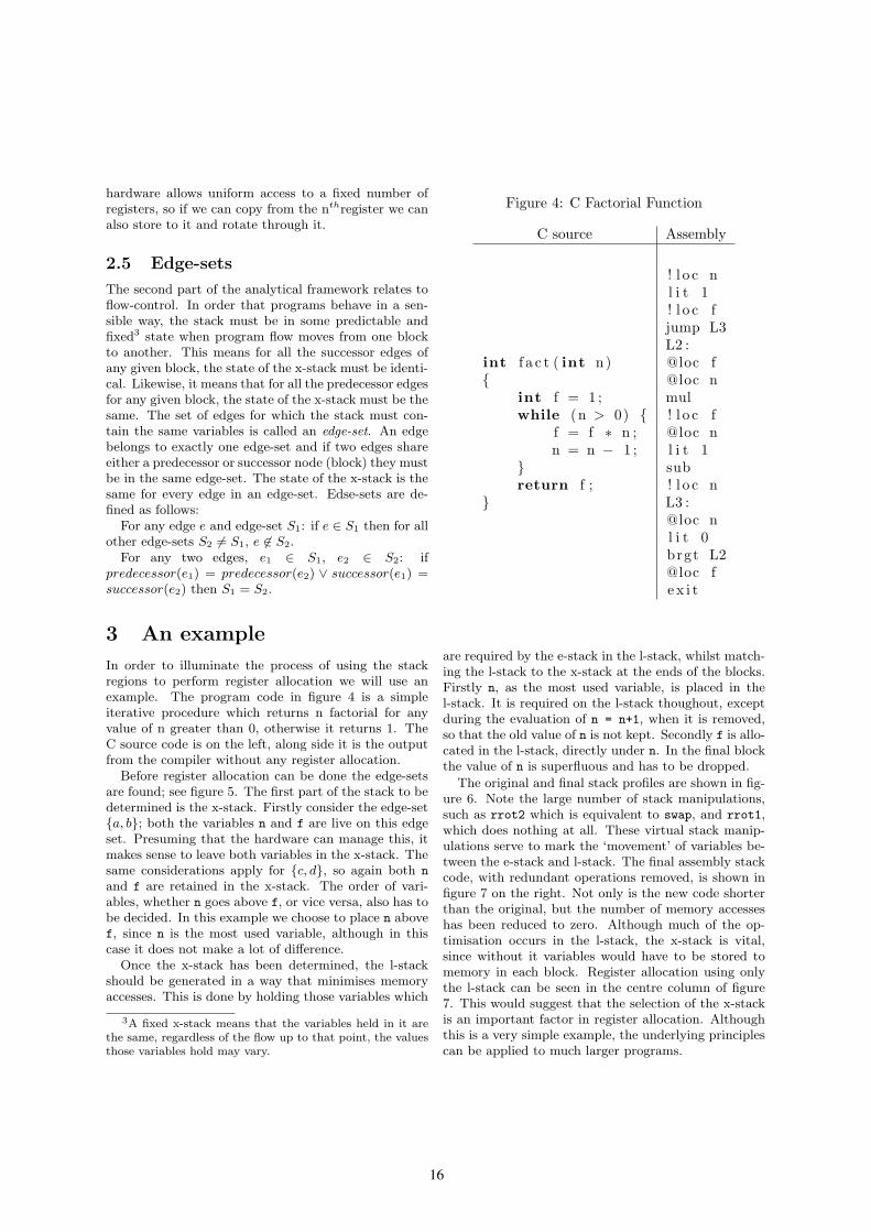
In order to illuminate the process of using the stackregions to perform register allocation we will use anexample. The program code in figure 4 is a simpleiterative procedure which returns n factorial for anyvalue of n greater than 0, otherwise it returns 1. TheC source code is on the left, along side it is the outputfrom the compiler without any register allocation.
Before register allocation can be done the edge-setsare found; see figure 5. The first part of the stack to bedetermined is the x-stack. Firstly consider the edge-set{a, b}; both the variables n and f are live on this edgeset. Presuming that the hardware can manage this, itmakes sense to leave both variables in the x-stack. Thesame considerations apply for {c, d}, so again both n
and f are retained in the x-stack. The order of vari-ables, whether n goes above f, or vice versa, also has tobe decided. In this example we choose to place n abovef, since n is the most used variable, although in thiscase it does not make a lot of difference.
Once the x-stack has been determined, the l-stackshould be generated in a way that minimises memoryaccesses. This is done by holding those variables which
3A fixed x-stack means that the variables held in it are
the same, regardless of the flow up to that point, the values
those variables hold may vary.
Figure 4: C Factorial Function
C source Assembly
int f a c t ( int n){
int f = 1 ;while (n > 0) {
f = f ∗ n ;n = n − 1 ;
}return f ;
}
! l o c nl i t 1! l o c fjump L3L2 :@loc f@loc nmul! l o c f@loc nl i t 1sub! l o c nL3 :@loc nl i t 0brgt L2@loc fe x i t
are required by the e-stack in the l-stack, whilst match-ing the l-stack to the x-stack at the ends of the blocks.Firstly n, as the most used variable, is placed in thel-stack. It is required on the l-stack thoughout, exceptduring the evaluation of n = n+1, when it is removed,so that the old value of n is not kept. Secondly f is allo-cated in the l-stack, directly under n. In the final blockthe value of n is superfluous and has to be dropped.
The original and final stack profiles are shown in fig-ure 6. Note the large number of stack manipulations,such as rrot2 which is equivalent to swap, and rrot1,which does nothing at all. These virtual stack manip-ulations serve to mark the ‘movement’ of variables be-tween the e-stack and l-stack. The final assembly stackcode, with redundant operations removed, is shown infigure 7 on the right. Not only is the new code shorterthan the original, but the number of memory accesseshas been reduced to zero. Although much of the op-timisation occurs in the l-stack, the x-stack is vital,since without it variables would have to be stored tomemory in each block. Register allocation using onlythe l-stack can be seen in the centre column of figure7. This would suggest that the selection of the x-stackis an important factor in register allocation. Althoughthis is a very simple example, the underlying principlescan be applied to much larger programs.

17
Figure 5: Determining the edge-sets
The edges a
and b share acommon child,so form oneedge set. Theedges c and d
share a commonparent and formanother edgeset. So, the twoedge-sets are{a, b} and {c, d}
4 Analysis of Existing Algo-
rithms
To demonstrate the value of the framework for anal-ysis we will look at Koopman’s and Bailey’s methodsfor ‘stack-scheduling’, and show that the algorithm canbe described more clearly and concisely with referenceto our framework. The improvements to Koopman’smethod by Maierhofer and Ertl are not covered, mainlyfor space reasons, as they add relatively little to Koop-man’s work in terms of performance.
4.1 Koopman’s algorithm
Koopman’s algorithm, as described in his paper, wasimplemented as a post processor to the textual outputof gcc[7] after partial optimisation. We have imple-mented it within lcc[3], where it acts directly on theintermediate form.
The algorithm is quite straightforward, as follows:
1. Clean up the output using simple peephole optimi-sation, replacing sequences of stack manipulationswith shorter ones if possible.
2. Locate define–use and use–use pairs of local vari-ables and list them in order of their proximity.That is, in ascending order of the number of in-structions separating the pair.
3. For each pair:
(a) Copy the variable at the point of definitionor first use to the bottom of the stack.
Figure 6: Stack profileBefore optimisation After optimisation
.text
param n n
rot1 n
!loc n
lit 1 1
!loc f
jump L3
L2:
@loc f f
@loc n nf
mul f*n
!loc f
@loc n n
lit 1 1n
sub n−1
!loc n
L3:
@loc n n
lit 0 0n
brgt L2
@loc f f
exit f
e-stack
l-stack
x-stack
.text
param n n
rot1 n
rrot1 n
lit 1 1n
rrot2 nf
jump L3 nf
L2: nf
rot2 fn
copy2 nfn
mul f*nn
rrot2 nf
rot1 nf
lit 1 1nf
sub n−1f
rrot1 nf
L3: nf
copy1 nnf
lit 0 0nnf
brgt L2 nf
rot1 nf
drop f
rot1 f
exit f
(b) Replace the second instruction with an in-struction to rotate the value to the top ofthe stack.
4. Remove any dead stores.
5. Reapply the peephole optimisation.
4.1.1 Koopman’s algorithm in terms of the
framework
In Koopman’s algorithm, when he refers to the bottomof the stack, he is referring to the portion of the stackused by the function being optimised. Since no inter-block allocation is done, thus the x-stack is empty, thebottom of the stack is clearly the bottom of the l-stack.Therefore step 3 above become:
(a) Copy the variable at the point of definitionor first use to the bottom of the l-stack.

18
(b) Replace the second instruction with an in-struction to rotate the value from the bottomof the l-stack to the top of the stack.
Figure 7: Assembly listings
No registerallocation
Localregisterallocation
Globalregisterallocation
! l o c nl i t 1! l o c fjump L3L2 :@loc f@loc nmul! l o c f@loc nl i t 1sub! l o c nL3 :@loc nl i t 0brgt L2@loc fe x i t
! l o c nl i t 1! l o c fjump L3L2 :@loc f@loc ntuck2mul! l o c fl i t 1sub! l o c nL3 :@loc nl i t 0brgt L2@loc fe x i t
l i t 1swapjump L3L2 :tuck2mulswapl i t 1subL3 :copy1l i t 0brgt L2drope x i t
4.2 Bailey’s ‘inter-boundary’ algo-
rithm
Bailey’s ‘inter-boundary’ algorithm was the first at-tempt to utilise the stack across basic block boundaries.This is done by determining edge-sets; although in thepaper the algorithm is defined in terms of blocks ratherthan edges. Then the x-stack, termed ‘sub stack in-heritance context’, is determined for the edge-set. Inoutline the algorithm runs as follows:
1. Find co-parents and co-children for a block (deter-mine the edge-set).
2. Create an empty ‘sub stack inheritance context’.
3. For each variable in a child block, starting withthe first to occur:
• If that variable is present in all co-parentsand co-children, then:
– Test to see if it can be added to the baseof the x-stack. This test is done for eachco-parent and co-child to see whetherthe variable would be reachable at theclosest point of use in that block.
Bailey’s algorithm is designed to be used as a comple-ment to an intra-block optimiser, such as Koopman’s.It moves variables onto the stack across edges in theflow graph, by pushing the variables onto the stack im-mediately before the edge and popping them off thestack immediately after the edge. Without an intra-block optimiser this would actually cause a significantperformance drop.
4.2.1 Bailey’s algorithm in terms of the
framework
1. Determine edge-sets
2. For each edge-set:
(a) Create an empty x-stack state for that edge-set.
(b) Determine the intersection of the sets of livevariables for each edge in the edge-set.
(c) Choose an arbitrary neighbouring block, pre-sumably the first to occur in the source code.
(d) For each variable in the intersection set, inincreasing order of the distance of usage fromthe edge in question:
• Test to see if it can be added to the x-stack, and if it can be, do so.
Although Bailey’s algorithm is an inter-block algo-rithm, it is not genuinely global, as it makes fairly lim-ited use of the x-stack. No values are left in the x-stackduring blocks. No attempt is made to integrate theallocation within the x-stack to allocation within thel-stack. In terms of performance, the main failing ofBailey’s algorithm is that it cannot handle variableswhich are live on some but not all edges of an edge-set.
5 A Global register allocator
The next step forward in register allocation for stackmachines, is to try to do it globally, in a procedurewide fashion. Once full data-flow information, includ-ing edge-sets, has been found, the next step is to deter-mine the x-stack on each edge-set. Our first approachwas to modify Bailey’s algorithm to use various combi-nations of unions and intersections of liveness and uses.

19
However, this revealed some important limitations inthe localised push-on, pop-off approach, which are:
• Excessive spilling
There is no attempt to make the x-stack similaracross blocks, so variables may have to be savedat the start of a block, and other variables loadedat the end of a block.
• Excessive reordering
Even when the x-stack state at the start and endof a block contain similar or the same variables,the order may be different and thus require extrainstructions.
• No ability to use the x-stack across blocks
The requirement for the entire x-stack to be trans-fered to the l-stack means that the size of the x-stack is limited. Variables cannot be stored deeperin the stack when they are not required.
5.1 A global approach
The problems to be solved are:
5.1.1 Determination of x-stack member
sets
Although none of the modified versions of Bailey’s al-gorithm produced better code than the original, someversions did seem to make promising selections of x-stack members. We decided to determine the x-stackset by starting with a large set of variables and reducingit towards an optimum.
5.1.2 Ordering of the variables within the
x-stack
If variables are to be kept on the x-stack during blocksthen the order of the lower parts of the x-stack is im-portant. Since the ordering of variables on the x-stackcannot be changed, without moving variables to the l-stack, the order of the lower parts of the x-stack must
match across blocks. The simple but effective approachtaken was to choose a globally fixed ordering. This alsosolves the problem of excessive reordering of variables.
5.1.3 Handling the l-stacks to work with
the x-stack
Since allocation of the l-stack depends on the x-stackat both beginning and end of the block. It is necessaryto determine the x-stack first. However, in order toallocate x-stack that do not impede l-stack allocation,the l-stack, must be at least partially determined beforethe x-stack.
5.2 Outline Algorithm
The algorithm chosen runs, in outline, as follows:
1. Determine edge-sets
2. Determine ordering of variables.
3. For each edge-set:
Determine x-stack using heuristic
4. For each basic block:
Do local allocation, ensuring l-stacks matchx-stack.
5.3 Determining x-stack
There are two challenges when determining the x-stack.One is correctness, that is, the x-stack must allow regis-ter allocation in the l-stacks to be both consistent withthe x-stack and legal. The other challenge is the qual-ity of the generated code. For example making all thex-stack empty is guaranteed to be correct, but not togive good code. Both the x-stack finding methods workby first using heuristics to find an x-stack which shouldgive good code, then correcting the x-stack, if necessary.The algorithm for ensuring correctness is the same, re-gardless of heuristic used.
For the x-stack to be correct, two things need to beensured:
1. Reachability
Ensure all variables in the x-stack that are definedor used in successor or predecessor blocks, are ac-cessible at this point.
2. Cross block matching
Ensure that all unreachable variables in the x-stack on one edge do not differ from those in thex-stack on an other edge adjoining the same block.
5.3.1 Ordering of variables.
As stated earlier, a globally fixed ordering of variables isused. This is done by placing variables with higher ‘es-timated dynamic reference count’ nearer the top of thestack. In our implementation, which is part of a portof lcc[3], the ‘estimated dynamic reference count’ is thenumber of static references to a variable, multiplyingthose in loops by 10 and dividing those in branches bythe number of branches that could be taken. An al-ternative ordering could be based around ‘density’ ofuse, which would take into account the lifetime of vari-ables. Profiling would provide the best estimate, but isimpractical.

20
5.3.2 Heuristics
We use two different heuristics to demonstrate the util-ity of the framework. The first is simple and fast,whereas the second is more complex, and consequentlyslower.
5.3.3 Global 1
The first simpler heuristic is simply to take the union
of live values. Its main flaw is that it selects variablesfor the x-stack, that cannot be allocated to the l-stack,and have to be spilled to memory.
5.3.4 Global 2
This heuristic was developed to improve on ‘Global 1’.It considers the ideal l-stack for each block and then at-tempts to match x-stack as closely to that as possible.Given that the ordering of variables is pre-determined,the x-stack can be treated as a set. In order to findthis set, we determine a set of variables which would becounter productive to allocate to the l-stacks. The x-stack is then chosen as the union of live values less thisset of rejected values. The set of ‘rejects’ is found by do-ing ‘mock’ allocation to the l-stack, to see which valuescan be allocated, then propagating the values to neigh-bouring blocks in order to reduce local variation in thex-stack. Overall this algorithm out performs ‘Global 1’,but can produce worse code for a few programs.
6 Results
The graph in figure 8 shows the simulated performanceof the various register allocation methods, for a simpleprocessor where memory accesses take three cycles andother operations take one cycle. The ‘overall’ result isthe geometric mean of the other results. Although theresults are for simple benchmarks on a simulated stackmachine, we believe that the differences between theprevious algorithms and the new ones are large enoughto be significant.
Figure 8: Relative performance
1
1,5
2
2,5
3
bsor
t
imag
e
mat
mul
fibfa
ct life
quick
quee
ns
tower
s
bitcnt
s
dhry
ston
ewf1
yacc
Ove
rall
koopman
bailey
global1
global2
7 Conclusion
As can be seen the global register allocation methodsare generally better than the previous methods, butthere is room for improvement. The framework laid outin this paper, enables us to analyse the two approaches,to see what those improvements could be, and can beused to find even better algorithms. Work is currentlyunderway to find an allocator that performs at least aswell as the two global allocators in all circumstances.
References
[1] C. Bailey. Inter-boundary scheduling of stackoperands: A preliminary study. Procedings of Eu-
roForth 2000, pages 3–11, 2000.
[2] J. Gosling, B. Joy, G. Steele, and G. Bracha. The
Java Language Specification, Second Edition. Addi-son Wesley, 2000.
[3] D. R. Hanson and C. W. Fraser. A Retargetable
C Compiler: Design and Implementation. AddisonWesley, 1995.
[4] P. Koopman, Jr. A preliminary exploration of opti-mized stack code generation. Journal of Forth Ap-
plication and Research, 6(3):241–251, 1994.
[5] T. Lindholm and F. Yellin. The Java Virtual Ma-
chine Specification. Addison-Wesley, 1996.
[6] M. Maierhofer and M. A. Ertl. Local stack alloca-tion. In CC ’98: Proceedings of the 7th Interna-
tional Conference on Compiler Construction, pages189–203, London, UK, 1998. Springer-Verlag.
[7] R. M. Stallman. Using and Porting the GNU Com-
piler Collection, For GCC Version 2.95. Free Soft-ware Foundation, Inc., pub-FSF:adr, 1999.

21
Optimizing Intel EPIC/Itanium2 Architecture for Forth Jamel Tayeb*, Smail Niar**
*Intel Corporation, Portland, Oregon (USA)
**LAMIH ROI, University of Valenciennes, (France)
[email protected], [email protected]
Abstract
Forth is a stack machine that represents a good match
for the register stack of the Explicit Parallel Instruction
Computer (EPIC) architecture. In this paper we will
introduce a new calling mechanism using the register stack
to implement a Forth system more efficiently. Based upon
our performance measurements, we will show that the new
calling mechanism is a promising technique to improve the
performance of stack-based interpretative languages such
as Forth. The limitation in EPIC’s Register Stack Engine
makes the need for hardware support to improve
performance and possibly close the efficiency gap with
specialized stack processors. We will define also an
adjustment to Itanium 2 processor’s instruction set to
accommodate the new calling mechanism and present a
conservative architectural implementation over the current
Itanium 2 processor’s pipeline.
1. Introduction
1.1. Background Virtual machines are an effective ways to take advantage
of the increasing chip and system-level parallelism –
introduced via technologies such as simultaneous multi-
threading [1], multi-core designs [2] and systems-on-a-chip
(networks) [3]. The performance of a virtual machine
depends on its implementation and its interaction with the
underlying processing architecture [4].
Just in Time [5] and Adaptive Dynamic Compilation [6]
techniques were developed to provide performance gain
over pure interpretation. In practice just in time and
adaptive dynamic compilation suffer some limitations. In
particular, it is difficult to explore a large set of
optimizations in a limited period of time. This issue makes
most just in time compilers to narrow down the field and the
scope of their optimizations. They also require additional
memory, which may be impractical in an embedded
environment.
1.2. Project aim The aim of our work is to close as much as possible the
theoretical efficiency gap that exists between EPIC (Explicit
Parallel Instruction Computer) [7] and stack processor
architectures while running Forth applications [8]. To do so,
we are comparing the Itanium 2 processor’s register stack to
existing stack processors’ architectures using Forth as their
assembly language (in section 6). Forth is used in the scope
of this study because it is a simple stack machine [9]. This
makes it well suited as a proxy for more sophisticated stack
machines such as .NET (The MSIL evaluation stack). In
addition, Forth’s key intrinsic advantages are:
� A low memory footprint;
� A high execution speed;
� The ability to interactively expand its dictionaries while
developing applications.
1.3. Why using EPIC? Itanium processors are today the only commercial chips
to implement the EPIC architecture. This processor family
is specifically targeting the enterprise server and high-
performance computing cluster segments. With 410 million
transistors required to implement the EPIC architecture in
the Itanium 2 processor (9MB on-chip cache memory), one
can argue that IPF doesn’t seem to be well suited for mid or
low range, or even embedded applications. However, the
EPIC architecture is not reserved to the high-end servers
and offers enough flexibility – I.e. the execution window
width of the machine – to adapt it to specific needs. It is
also interesting to notice that the Itanium 2 processor core
uses less than 30 million transistors to implement the
processor’s logic (where a modern x86, out-of-order
execution engine’s implementation requires 40+ million
transistors). The reminder of the transistors budget is
essentially dedicated to build the huge on-chip cache
memory (Level 3 essentially). It is therefore realistic to
consider the design of a low-end processor based on EPIC
architecture and having a limited amount of on-chip cache
memory (128KB L2 and/or 1MB L3). In consequence of
that:
� EPIC architecture, with its large register file and
its simple and in-order core makes it well suited
to host a stack machine, such as Forth,
� Itanium 2 processor is a good development
vehicle and the best performance proxy available
for our initial study.
1.4. Plan We first introduce in section 2 a new Stack Indexed
Register (SIR) based on Itanium 2 processor’s register stack
to implement a purely software virtual machine, running
Forth. Based upon our performance projections
(summarized in section 5), we demonstrate that the
proposed mechanism is a promising technique to improve
the performance of stack-based interpretative virtual
machine. But limitation in EPIC’s register stack engine
makes the need for a hardware support to reach optimal

22
performance and close as much as possible the theoretical
efficiency gap with stack processors (detailed in section 6.1
– related projects). In section 3, we define an addition to
Itanium 2 processor’s instruction set to accommodate the
SIR. In section 4, we describe a conservative architectural
implementation of the extended instruction set. We
summarize our experimental results in section 5 and present
our conclusions in section 7.
2. The New Calling Convention Our reference Forth virtual machine is threaded and uses
in-memory stacks. Parameter passing is done through the
stack, and an optimizing compiler (Microsoft Visual C++
2005 for Itanium) is used to generate the binary of words
defined in the X3.215-1994 ANS standard [10]. Assembly
coding is done using ias, the Intel EPIC assembler.
First, to present the use by compilers of the Itanium 2
processor register stack, let’s examine a function call using
the address interpreter’s principal statement – performing
NEXT: (pf->internals.ip->cfa)(pf);
The translation of this statement by the compiler in EPIC
assembly language is given in Table 1.
Table 1 - Translation in the EPIC assembly language of (pf->internals.ip->cfa)(pf);
1
2
3
4
5
6
7
8
9
10
11
12
13
14
15
{ .mii
alloc r35=2,3,1,0
mov r34=b0
adds r31=528, r32
} … { .mmb
mov r36=gp
mov r37=r32
nop.b 0;;
} { .mmi
ld8 r30=[r31];;
ld8 r29=[r30]
nop.i 0;;
} { .mmi
ld8 r28=[r29], 8;;
ld8 gp=[r29]
mov b6=r28
} { .mmb
nop.m 0
nop.m 0
br.call.dptk.many b0=b6;;
}
The function call itself is clear enough – the target
address is stored in the b6 branch register (instruction 12
and 15 for the actual branching). The key operation for the
function call mechanism is the alloc instruction (instruction
1). It allocates a new stack frame to the register stack. By
specifying the number of input, output, local – and rotating
registers – required at the beginning of the procedure to the
register stack engine, the caller sets the arguments for the
callee. Note that the alloc instruction can be used anywhere
in a program and as many times as needed. Any consecutive
instruction to the alloc will immediately see the renamed
registers. Here, the pf pointer is directly and always
available in the general-purpose register r32 and can be used
right away to compute the interpreting pointer (ip) address.
This mechanism is well suited to support object-oriented
languages which tend to be dominated by calls to low
instruction-count functions.
Even if the register stack engine provides an efficient way
to pass arguments back and forth all along the call stack, our
reference Forth implementation still has to manage its in-
memory stacks. In consequence, we introduce our SIR to
allow the compiler to keep the entire – or partial – Forth
stack in the register stack.
Let’s consider the simple + word, summing two numbers
on the stack. The reference code in C is: void CORE_PLUS(PFORTH pf) {
int3264 n1, n2;
POP(n2); POP(n1); PUSH(n1 + n2);
}
In the proposed mechanism, a sub-set of the Itanium 2
processor register file (the stacked registers) is recycled as
an in-register data and floating-point stack. The return stack
can either be mapped into the branch registers of the
processor or in the general purpose register file. The major
technical difficulty consists here in maintaining the stack
size in the Forth interpreter – forcing the Forth compiler to
compute the words’ arity – and using self-modifying code to
adjust the alloc instruction’s arguments accordingly after
each return from the primitives. This coding technique leads
to a functional Forth engine but suffers some limitations.
The alloc instruction cannot allocate a stack frame larger
than 96 registers. Yet, if needed, additional stack elements
are spilled / filled by the register stack engine into the
backing store memory, with a performance overhead. A
secondary limitation of using the stacked registers as in-
register stack is that it may limit the use of the software
pipelining (a key performance technique for Itanium 2
processor [11]) within the Forth words by the compiler.
As soon as the stack size limitation is satisfied, we can
support the Forth virtual machine in a much more efficient
way. It is noticeable that the performance benefit of the SIR
is increasing proportionally with the amount of stack
handling primitives used by the code. The entire execution
of + can now be scheduled for only two processor cycles as
shown in the next listing. Note that this code was hand-
written and differs therefore from the compiler generated
assembler listed in table 1 – not showing the bundles
explicitly. .global SIR_CORE_PLUS
.type SIR_CORE_PLUS, @function
.proc SIR_CORE_PLUS
pfs = r34
SIR_CORE_PLUS:
;alloc placeholder
alloc pfs = 2, 1, 1, 0 ;default arity
add out0 = in0, in1
mov ar.pfs = pfs
br.ret.sptk.many b0

23
.endp
Table 2 compares the principal characteristics of both
implementations of +. A bundle is a group of three
instructions. A stop bit is introducing a serialization in the
instruction stream.
Table 2 - Characteristics of the two versions of +.
Features Reference
Implementation
Proposed optimized
implementation
I/FP registers 9/0 2/0
Bundles 14 2
Nops 5 3
Stop bits 10 1
Branches 6 1
Loads 6 0
Stores 1 0
The second advantage of the SIR is that we can still
entirely rely upon the register stack engine to trap and
process stack overflow exceptions in exchange of a
performance penalty. When such condition happens during
the execution of the alloc instruction – I.e. insufficient
registers are available to allocate the desired stack frame –
the processor stalls until enough dirty registers are written to
the backing store area (these stall cycles can be monitored
for optimization purpose through the BE_RSE_BUBBLE-
ALL performance counter [12]).
Alas, EPIC doesn’t provide the same register-passing
mechanism for floating-point arguments. This lack makes
necessary to manage the floating-point register file
explicitly to implement the SIR, making the compiler more
complex and asymmetrical for integer and floating-point
stack handling. But having a large on-chip floating-point
register file (128 registers) and the associated computing
resources (2 floating-point execution units capable of vector
operations – up to 4 FLOP per cycle) still provides a
considerable performance advantage over stack processors
for floating-point intensive codes.
By using Itanium 2 processor’s register files as in-register
stacks, it is possible to eliminate:
� The need for the pop / push primitives, which are
embedded into the EPIC Register Stack Engine – at
least for the integer operations;
� The multiple clock-cycle floating-point load
instructions required for passing the argument via the
in-memory floating-point stack (for reference: 13
cycles for L3 hit, 6 cycles for L2 hit and 1 cycle for L1
hit – integer data only in L1D);
� The energy consumption and power dissipation
associated with the suppressed loads / stores from / to
cache / memory.
With the Itanium 2 processor, up to 96 general purpose
registers can be used to implement the Forth data stack and
96 floating-point registers to implement the optional
floating-point stack. In our implementation, the data is
mapped as follows:
� Data stack: r32-r127,
� floating-point stack: f32-f127,
� And Return stack: b6-b7 (can be mapped into the
integer register file).
Our software implementation of the SIR has an additional
drawback when it is used in conjunction of the standard
calling mechanism. It requires extra code and processor
cycles to ensure the register spilling / filling when switching
between calling conventions. This is currently mitigating
the performance gains on applicative benchmarks1 as only a
limited set of Forth primitives are implemented using the
SIR.
3. Enhancing the Itanium 2 processor
instruction set to Support SIR To overcome the software implementation’s limitation
and to generalize the SIR’s usage between the integer and
floating-point register files, we propose a global hardware
indexed access to the register files. We assume the
following notations: gr[reg] or gr[imm] and fr[reg] or
fr[imm] where:
� gr is the general-purpose register file and fr is the
floating-point register file;
� reg is the register that holds the index into the register
file;
� imm is the index value into the register file.
Here after, we will describe only the integer case as the
floating-point case can be directly derived. Let’s assume the
following convention for the stack index registers to recode
the Forth virtual machine with the modified instruction set:
� Index to Data Stack TOS (gr_tos) = r2;
� Index to Data Stack level 1 (gr_l1) = r3;
� Index to Data Stack level 2 (gr_l2) = r14;
� Index to Forth Data Stack level 3 (gr_l3) = r15.
These registers were selected to simplify the co-existence
of SIR with the standard calling convention as they are
unused and unsaved during standard calls. However, any
register (lower than r32 and fr32 could be used as indexes –
at the exception of the read-only r0, r1, f0 and f1 registers).
In consequence, coding + no longer requires the register
stack engine and the integer data stack is managed in the
same way as the floating-point stack. The required
comparison and the extra additions needed to detect the
stack underflow situation and to maintain the stack pointers
up-to-date are not penalizing because of the underlying
VLIW nature of the EPIC architecture. This allows us to
reuse the otherwise empty (nop) bundle slots to perform the
required operations. It is also interesting to notice that the
predicate registers (p6 and p0) allow expressing the test and
the branch instruction if true in a very compact way. With
our proposed instruction set addition, the code for +,
embedding the stack management can still be scheduled for
two processor cycles and is listed below: .global SIR_CORE_PLUS
1 This overhead can be removed by coding the entire Forth virtual
machine in assembler using our SIR rather than using also a C++ compiler
– a task which is out of the scope of this study.

24
.type SIR_CORE_PLUS, @function
.proc SIR_CORE_PLUS
SIR_CORE_PLUS:
cmp4.lt.unc p6, p0 = 32, gr_tos
(p6) br.cond.dptk.many
@underflow_exception;;
add gr[gr_l1] = gr[gr_tos],
gr[gr_l1];;
mov gr_tos = gr_l1;;
add gr_l1 = -1, gr_tos
add gr_l2 = -2, gr_tos
add gr_l3 = -3, gr_tos
br.ret.sptk.many b0;;
.endp
4. A Conservative Implementation By limiting further the number of registers used as our in-
register stacks to 64 we can propose a conservative
architectural implementation of the SIR that would not
require an instruction set modification. The new simplified
logical view of the register files and the in-register stacks is
shown in Figure 1. It is the compiler’s responsibility to
enforce the segregation between the in-register stacks and
the traditional register file.
We first define a new indexed capability for the higher 64
registers identified via the CPUID instruction. An additional
bit in the status register indicates if the functionality is
enabled. If not, the additional Register Alias Table (RAT)
required by our implementation – described later – is
bypassed and no recompilation of existing code is required
to run as-is. A compiler willing to use the SIR has to check
if the functionality is available – on the target system – and
to activate at runtime the in-register stacks by updating the
status register.
Figure 1 - Snapshoot showing the logical view of the
integer register file. In grey the recycled register files subset as in-register stacks. Arrows represent the
indexing.
When the in-register stacks are active, the EXP (Template
decode, Expand and Disperse) stage of the core pipeline has
to check, per instruction, if the MSB of a source register is
set (noted MSB Detect in Figure 2). If not, then the normal
execution of the instruction takes place. If the MSB is set
for at least one register, then the additional RAT checks if
the target register is to be modified by an instruction
currently executed. To track the status (ready / not ready) of
the target registers, the RAT uses a 64 x 1 bit vector. If the
corresponding ready bit is set, then the RAT feeds into the
REN stage the new register address (using a multiplexer and
a latch - one per indexed register – holding the 6 bits of the
real register address in the register file (noted Index Register
Cache in Figure 2). If the register is marked as not ready in
the RAT, then a serialization must take place, and a pipeline
stall happens. Once the target register is ready, its value if
forwarded into its corresponding latch of the RAT, which
updates the register’s status bit. The stalled instruction’s
execution can therefore be resumed.
Our simplified implementation allows indexed access to
only 64 registers in the integer and floating-point register
files. It also requires 1 bit in the CPUID, 1 bit in the status
register and an MSB bit-set detection during the early stages
of the instruction decoding. It also requires a 64-entry RAT
using 64 x 6-bit latches and multiplexers, plus 64 x 1 status
bit vector; and adds an extra execution cycle to the main
pipeline. In return, it provides the following advantages:
� Implements the required integer and floating-point in-
register stacks, under the compiler’s control (limited to
64-integer and 64 floating-point entries);
� It is possible to implement with the actual Itanium
processor pipeline;
� It is totally compatible with existing software;
� It also allows:
• The suppression of the loads / stores associated
with stack operations (hence ensuring performance
gains over C code);
• The substantial reduction of the chip’s power
consumption when executing stack handling
routines, a dominant in Forth applications and
virtual machines in general.
Figure 2 - the current – simplified – main pipeline (top) and the modified one (bottom). Additional
structures are marked in grey.
5. Experimental Results In this section, we present the results of our experimental
software implementation of the SIR. We have benchmarked
11 major stacks handling Forth words along with the integer
and floating-point additions. Each of these words was
recoded using the software implementation of the SIR.
Performance was measured by averaging the number of
processor cycles required to execute a billion occurrences of
each word (measured by using the processor’s interval time
counter application register – ar.itc). Our performance
measurements demonstrate that it is appropriate to consider
the EPIC register files as a set of in-register stacks to run a
25
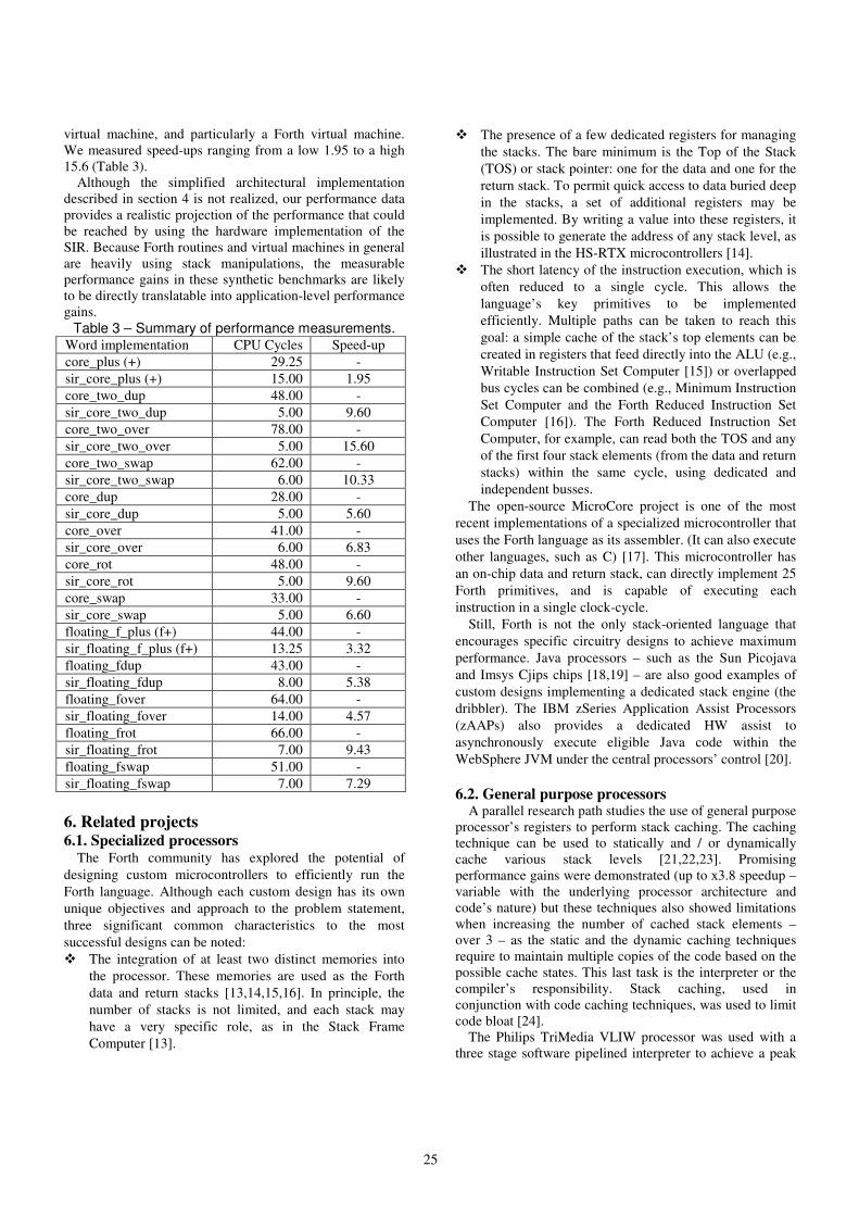
virtual machine, and particularly a Forth virtual machine.
We measured speed-ups ranging from a low 1.95 to a high
15.6 (Table 3).
Although the simplified architectural implementation
described in section 4 is not realized, our performance data
provides a realistic projection of the performance that could
be reached by using the hardware implementation of the
SIR. Because Forth routines and virtual machines in general
are heavily using stack manipulations, the measurable
performance gains in these synthetic benchmarks are likely
to be directly translatable into application-level performance
gains.
Table 3 – Summary of performance measurements. Word implementation CPU Cycles Speed-up
core_plus (+) 29.25 -
sir_core_plus (+) 15.00 1.95
core_two_dup 48.00 -
sir_core_two_dup 5.00 9.60
core_two_over 78.00 -
sir_core_two_over 5.00 15.60
core_two_swap 62.00 -
sir_core_two_swap 6.00 10.33
core_dup 28.00 -
sir_core_dup 5.00 5.60
core_over 41.00 -
sir_core_over 6.00 6.83
core_rot 48.00 -
sir_core_rot 5.00 9.60
core_swap 33.00 -
sir_core_swap 5.00 6.60
floating_f_plus (f+) 44.00 -
sir_floating_f_plus (f+) 13.25 3.32
floating_fdup 43.00 -
sir_floating_fdup 8.00 5.38
floating_fover 64.00 -
sir_floating_fover 14.00 4.57
floating_frot 66.00 -
sir_floating_frot 7.00 9.43
floating_fswap 51.00 -
sir_floating_fswap 7.00 7.29
6. Related projects 6.1. Specialized processors
The Forth community has explored the potential of
designing custom microcontrollers to efficiently run the
Forth language. Although each custom design has its own
unique objectives and approach to the problem statement,
three significant common characteristics to the most
successful designs can be noted:
� The integration of at least two distinct memories into
the processor. These memories are used as the Forth
data and return stacks [13,14,15,16]. In principle, the
number of stacks is not limited, and each stack may
have a very specific role, as in the Stack Frame
Computer [13].
� The presence of a few dedicated registers for managing
the stacks. The bare minimum is the Top of the Stack
(TOS) or stack pointer: one for the data and one for the
return stack. To permit quick access to data buried deep
in the stacks, a set of additional registers may be
implemented. By writing a value into these registers, it
is possible to generate the address of any stack level, as
illustrated in the HS-RTX microcontrollers [14].
� The short latency of the instruction execution, which is
often reduced to a single cycle. This allows the
language’s key primitives to be implemented
efficiently. Multiple paths can be taken to reach this
goal: a simple cache of the stack’s top elements can be
created in registers that feed directly into the ALU (e.g.,
Writable Instruction Set Computer [15]) or overlapped
bus cycles can be combined (e.g., Minimum Instruction
Set Computer and the Forth Reduced Instruction Set
Computer [16]). The Forth Reduced Instruction Set
Computer, for example, can read both the TOS and any
of the first four stack elements (from the data and return
stacks) within the same cycle, using dedicated and
independent busses.
The open-source MicroCore project is one of the most
recent implementations of a specialized microcontroller that
uses the Forth language as its assembler. (It can also execute
other languages, such as C) [17]. This microcontroller has
an on-chip data and return stack, can directly implement 25
Forth primitives, and is capable of executing each
instruction in a single clock-cycle.
Still, Forth is not the only stack-oriented language that
encourages specific circuitry designs to achieve maximum
performance. Java processors – such as the Sun Picojava
and Imsys Cjips chips [18,19] – are also good examples of
custom designs implementing a dedicated stack engine (the
dribbler). The IBM zSeries Application Assist Processors
(zAAPs) also provides a dedicated HW assist to
asynchronously execute eligible Java code within the
WebSphere JVM under the central processors’ control [20].
6.2. General purpose processors A parallel research path studies the use of general purpose
processor’s registers to perform stack caching. The caching
technique can be used to statically and / or dynamically
cache various stack levels [21,22,23]. Promising
performance gains were demonstrated (up to x3.8 speedup –
variable with the underlying processor architecture and
code’s nature) but these techniques also showed limitations
when increasing the number of cached stack elements –
over 3 – as the static and the dynamic caching techniques
require to maintain multiple copies of the code based on the
possible cache states. This last task is the interpreter or the
compiler’s responsibility. Stack caching, used in
conjunction with code caching techniques, was used to limit
code bloat [24].
The Philips TriMedia VLIW processor was used with a
three stage software pipelined interpreter to achieve a peak

26
sustained performance of 6.27 cycles per instruction [25].
Interpretation is used by the authors to compress non-time-
critical code, where time-critical-code is compiled to native
code.
7. Conclusions We presented an innovative use model for the Itanium 2
processor register files to improve Forth systems’
performance running on EPIC architecture. Synthetic
benchmarking shows an average 7x performance increase
over the code generated by a state-of-the-art C/C++
compiler, using EPIC’s standard calling convention (from
1.95x up to 15.6x).
Based upon our findings and coding experiments, we
introduced an adjustment to the Itanium 2 processor
instruction set offering indexed register file access, to ease
Forth systems’ implementation and increase its efficiency.
We then proposed an architectural implementation of a
limited version of the adjustment – by restricting the size of
the Forth integer and floating-point in-register stacks to 64
entries each –, making it conceivable to implement into the
current Itanium 2 processor’s pipeline. If realized, this
adjustment should lead to a more efficient use of the register
files to host a virtual machine’s data and control stacks. By
mapping the Forth stacks into the register files instead of the
main memory, the load and store operations associated to
the stack handling primitives would be suppressed, allowing
performance gains associated to power savings.
8. Acknowledgment The authors would like to thank Intel Corporation and
particularly the Microprocessor Technology Labs
(http://www.intel.com/technology/computing/mtl/) for the
support given to this work. We also would like to thank the
referees for their insightful comments that have improved
this paper.
9. References [1] D. Tullsen, S. Eggers, and H. Levy: “Simultaneous
Multithreading: Maximizing On-Chip Parallelism”, in Proceedings of the 22nd AISCA conference, June 1995.
[2] P. P. Gelsinger, Intel Corporation, Hillsboro, OR, USA: “Microprocessors for the New Millennium –Challenges, Opportunities and New Frontiers”, in IEEE ISSC, 2001.
[3] L. Benini and G. De Micheli: “Networks on Chip: A New Paradigm for System on Chip Design”, in Proceedings of the 2002 DATE conference 2002.
[4] J. Smith and R. Nair: “Virtual Machines: Versatile Platforms for Systems and Processes”, Elsevier Science & Technology Books, May 2005.
[5] T. Shpeisman, G-Y. Lueh and A-R. Adl-Tabatabai, “Just-In-Time Java Compilation for the Itanium Processor”, 11th PACT conference, 2002, p. 249.
[6] D. Bruening, T. Garnett and S. Amarasinghe, “An infrastructure for adaptive dynamic optimization”, Code Generation and Optimization, 2003, pp. 265-275.
[7] M. S. Schlansker and B. Ramakrishna Rau: “EPIC: Explicitly Parallel Instruction Computing”, in IEEE Computer Society Press, Volume 33, Issue 2 (February 2000), pp 37-45.
[8] E. D. Rather, D. R. Colburn and C. H. Moore, “The Evolution of Forth”, ACM SIGPLAN Notices, Volume 28, No. 3, March 1993.
[9] P. Koopman, Jr.: “Stack Computers: the new wave”, Ellis Horwood (1989), republished on the World Wide Web by Mountain View Press.
[10] American National Standard for Information System, Technical Committee X3J14, “X3.215-1994: Programming Languages – Forth”, 1994.
[11] S. Niar and J. Tayeb: « Programmation et Optimisation d'Applications pour les Processeurs Intel Itanium », Editions Eyrolles, January 2005.
[12] Intel Corporation, “Intel Itanium 2 Processors Reference Manual for Software Development and Optimization”, Volumes 1, 2 and 3.
[13] R. D. Dixon, M. Calle, C. Longway, L. Peterson and R. Siferd: “The SF1 Real Time Computer” Proceedings of the IEEE National Aerospace and Electronics Conference, Dayton, OH, Vol. 1, pp. 60-64, May 1988.
[14] T. Hand: "The Harris RTX 2000 Microcontroller", Journal of Forth Application and Research, Vol. 6, No. 1, pp. 5-13, 1990; and the Interstil “Radiation Hardened Real Time Express™ HS-RTX2010RH Microcontroller Data Sheet.
[15] P. Koopman: "Writable Instruction Set Stack Oriented Computers: The WISC Concept", Journal of Forth Application and Research (Rochester Forth Conference Proceedings), vol. 5, no. 1, pp. 49-71, 1987.
[16] J. R. Hayes and S. C. Lee: "The Architecture of FRISC 3: A Summary", 1988 Rochester Forth Conference Proceedings, 1988, Institute for Applied Forth Reserch Inc.
[17] K. Schelisiek: “MicroCore: an Open-Source, Scalable, Dual-Stack, Hardware Processor Synthesisable VHDL for FPGAs”, euroForth 2004.
[18] J. Michael O’Connor and Marc Tremblay, “PicoJava-i: The Java Virtual Machine in Hardware”, Micro, IEEE, Volume 17, Issue 2, March-April 1997, pp. 45-53.
[19] Imsys Technologies AB, “IM1101C – the Cjip – Technical Reference Manual”, www.imsys.se/documentation/manuals/tr-CjipTechref.pdf, 2004.
[20] IBM Redbook on zAAP: SG24-6386 (www.redbooks.ibm.com)
[21] A. Ertl and D. Gregg: “Stack Caching in Forth”, in EuroForth 2005.
[22] A. Ertl:. “Stack Caching for Interpreters”, in SIGPLAN '95 Conference on Programming Language Design and Implementation, pp. 315-327, 1995.
[23] K. Ogata, H. Komatsu and T. Nakatani: "Bytecode Fetch Optimization for a Java Interpreter", in ASPLOS 2002, pp. 58-67, 2002.
[24] P. Peng, G. Wu and G. Lueh: "Code Sharing among States for Stack-Caching Interpreter", in Proceedings of the 2004 workshop on Interpreters, virtual machines and emulators, pp. 15-22, 2004.
[25] J. Hoogerbrugge, L. Augusteijn, J. Trum, R. van de Wiel: “A Code Compression System Based on Pipelined Interpreters. Software – Practice and Experience 29(11): 1005-1023, 1999.

27
Adding Lambda Expressions to Forth
Angel Robert Lynas and Bill Stoddart
August 4, 2006
Abstract
We examine the addition of Lambda expressions to Forth. We brieflyreview the Lambda calculus and introduce a postfix version of Lambdanotation to guide our approach to a Forth implementation. The resultingimplementation provides the basic facilities of an early binding functionallanguage, allowing the treatment of functions as first-class objects, ma-nipulation of anonymous functions, and closures.
1 Introduction
The Lambda Calculus was developed by Alonzo Church during the 1930’s as ageneral model of computation [4]. The original motivation was to investigatethe notion of solvability [3], but the Calculus later formed a theoretical ba-sis for functional programming. Recently there has been an interest in adding“lambda expressions” to imperative languages. They are proposed for vsn 3.0of C#, but are not yet part of the ECMA C# Standard[1] which does how-ever, largely support their functionality through “anonymous methods”. TheOpen Standards Working Group for C++ recently produced a discussion paper”Lambda expressions and closures for C++”[8]. In this paper we discuss theirincorporation within RVM Forth [5].
The functional programming (FP) paradigm arises from the mathematical ideaof a function as a mapping from inputs to outputs; a procedure inside thefunction (the “body”) operates on a variable to produce a return value in termsof that variable. The variable is instantiated by an argument to the function’ssingle parameter, and the return can be numeric or some other type, includinganother function. In FP, therefore, functions are treated as first-class objects,that is, having the same status as variables and constants; they can also bearguments to functions, and manipulated as temporary anonymous objects.
While Forth does have some facilities to work with functions and operationswith the stack, using execution tokens and allowing vectored execution, it doesnot provide the full generality required by the functional programming model.

28
Implementing a Lambda facility in Forth presents certain points of interest.A consistent postfix syntax must be developed, and to guide our design wehave produced a postfix version of Lambda notation. The function objectsproduced must be dealt with in a consistent way to maintain compatibility withthe abstract idea of the calculus, and the use of bound and free variables inLambda calculus has to be integrated with the use of stack-frame local variablesin RVM-Forth, requiring the provision of “closures” for dynamically-createdfunctions.
In the rest of the paper, we provide a brief introduction to Lambda Calculus, itsexpression in postfix form, and the RVM-Forth implementation. We examinethe roles of local variables and their binding in Lambda calculus, and how thiscan be integrated with a local variable system in a procedural language, suchthat persistent bindings can be maintained despite them having originated in alocal context. Finally we review the ongoing project of which this work forms apart. A more detailed view of our implementation techniques is included as anappendix.
2 Lambda Calculus
2.1 Lambda Calculus
The general form for a lambda expression is:
λ < name > . < body >
In the above, <name> is the parameter or bound variable in the function —lambda functions have a single parameter only. The process of substituting anargument for the parameter in an application is known as β-reduction (shown
asβ
−→ ), which substitutes occurrences of the bound variable in the body withthe argument expression. Once thus instantiated, the variable cannot changevalue.
The <body> itself can be anything from a simple operation on the variable toother nested functions, including embedded function applications.
The simplest example would be the identity function:
λ x .x
which returns its argument; so
(λ x .x ) aβ
−→ a
For further examples, we allow the use of arithmetic operations1 So the func-
1Neither these nor numbers are initially present in the basic lambda calculus, which is
concerned with representing them in terms of more primitive substitution patterns.

29
tions:
λ x .x + 1λ x .x ∗ x
would respectively increment their argument by one, and square it.
(λ x .x ∗ x ) 5β
−→ 5 ∗ 5 = 25 (1)
These examples all have a single bound variable in the body; variables in thebody which are not bound by the immediate lambda declaration are known asfree variables; these make little sense computationally unless they are in turnbound by an enclosing function. In this example:
λ y .x − y (2)
the variable x is free. It may, however be bound by an enclosing function whosebody is (2):
λ x .(λ y .x − y)
This is the basic way to deal with two or more arguments in Lambda calculus.The variable x has now become a local variable from an outer scope. We usean eager evaluation approach which requires it to be instantiated before theexpression containing it is evaluated.
As regards application, parameters from left to right (i.e. outermost first) aresubstituted by arguments in the same direction, thus in an application of theabove:
(λ x .(λ y .x − y)) 10 3β
−→ (λ y .10 − y) 3 (3)
The first reduction, substituting 10 for x , now returns a function which subtractsits argument from 10; here y would be substituted by 3 in the next reduction.
β
−→ 10 − 3 = 7
An argument may well be another function. The expression:
λ f .(λ y .f y)
is a function that applies any given function f to any given argument y , forinstance given the function λ x .x + 1 for f and the number 7 for y
(λ f .(λ y .f y)) (λ x .x + 1) 7β
−→ (λ y .(λ x .x + 1) y) 7β
−→ (λ x .x + 1) 7β
−→ 7 + 1 = 8

30
2.2 A Postfix Notation for Lambda Calculus
Function application in Lambda notation is usually shown by a bracketed func-tion followed by an argument. Postfix will require the argument to appear first.Conventional Lambda notation uses brackets to delimit the scope of a boundvariable, and for that we will use a specific endλ symbol. Finally conventionalLambda notation uses brackets to control when a function is applied so it can betaken from the stack, followed by a definition body or a symbol (defined earlier)standing for it. However, this would not be automatically applied; an additionalsymbol is required analogous to Forth’s EXECUTE. The symbol we use for this
is a tick ′ . This usage has a history going back at least as far as PrincipiaMathematica, where the application of function f to an argument x is writtenas f ′x .
We can now present some examples from the earlier section in an abstractpostfix notation, with the actual RVM-Forth code in the next section. We usethe notation infix ; postfix to show how the infix and postfix formscorrespond. Taking example (1), we have:
(λ x .x ∗ x ) 5 ; 5 λ x .x x ∗ endλ ′
The keyword endλ ends the anonymous definition; at this point it could beassigned to a suitable variable, or applied, or left on the stack. The tick ensuresapplication. Instantiation of the variable x by 5 (beta reduction) now yields thepostfix expression “5 5 ∗”.
The nested definition example (3), runs thus:
(λ x .(λ y .x − y)) 10 3 ;
3 10 λ x . λ y .x y − endλ endλ ′ ′
Note that the arguments follow a stack order, first at the top. Above that is thefunction, however, with outer and inner variables as yet uninstantiated. Thereturn value of the outer function will be the inner function with its unboundvariables bound.
The first tick will execute the outer definition (λ x ), which will instantiate x
(anywhere within scope) to the value 10 from the top of the stack:
β
−→ 3 λ y .10 y − endλ ′
This leaves 3 and the inner function on the stack — now with its x bound to aconstant. The remaining tick executes this, instantiating y to 3, and returning“10 3 −”.
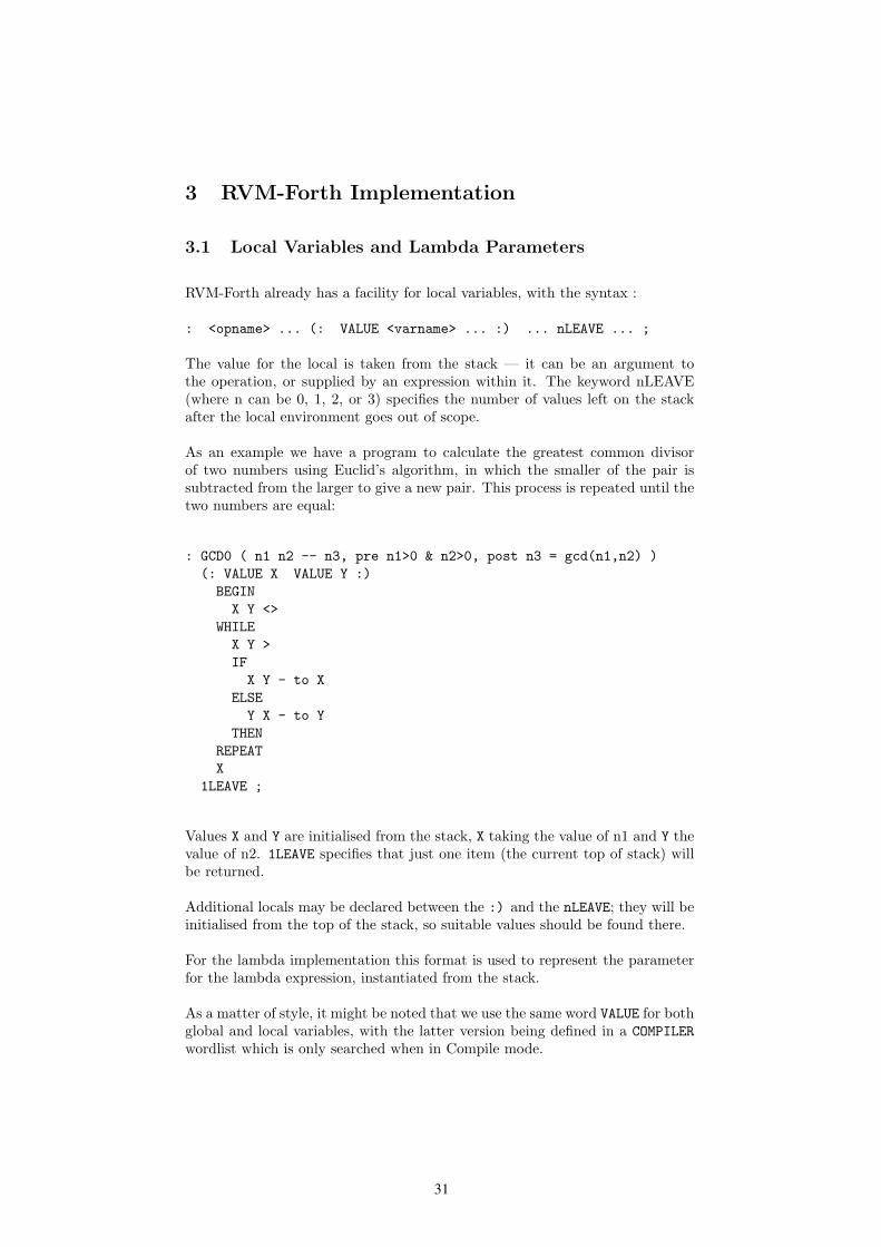
31
3 RVM-Forth Implementation
3.1 Local Variables and Lambda Parameters
RVM-Forth already has a facility for local variables, with the syntax :
: <opname> ... (: VALUE <varname> ... :) ... nLEAVE ... ;
The value for the local is taken from the stack — it can be an argument tothe operation, or supplied by an expression within it. The keyword nLEAVE(where n can be 0, 1, 2, or 3) specifies the number of values left on the stackafter the local environment goes out of scope.
As an example we have a program to calculate the greatest common divisorof two numbers using Euclid’s algorithm, in which the smaller of the pair issubtracted from the larger to give a new pair. This process is repeated until thetwo numbers are equal:
: GCD0 ( n1 n2 -- n3, pre n1>0 & n2>0, post n3 = gcd(n1,n2) )
(: VALUE X VALUE Y :)
BEGIN
X Y <>
WHILE
X Y >
IF
X Y - to X
ELSE
Y X - to Y
THEN
REPEAT
X
1LEAVE ;
Values X and Y are initialised from the stack, X taking the value of n1 and Y thevalue of n2. 1LEAVE specifies that just one item (the current top of stack) willbe returned.
Additional locals may be declared between the :) and the nLEAVE; they will beinitialised from the top of the stack, so suitable values should be found there.
For the lambda implementation this format is used to represent the parameterfor the lambda expression, instantiated from the stack.
As a matter of style, it might be noted that we use the same word VALUE for bothglobal and local variables, with the latter version being defined in a COMPILER
wordlist which is only searched when in Compile mode.

32
Arrays and pointers to arrays are implemented in RVM-Forth, and they alsohave their local analogues. The declarations here for both global and localare VALUE-ARRAY and VALUE-ARRAY^ (the full syntax is described in the RVMManual [5]. We present a brief example below, though not of a kind that onewould ever use. A global array is declared and initialised:
4 VALUE-ARRAY GLOBARR ( 4-element storage )
HERE 4 , 10 , 20 , 30 , 40 , to GLOBARR
.GLOBARR 10 20 30 40 ok ( Demo print defined offstage )
Next an operation is defined to reverse the elements in it. This has a localpointer to the global array, and an internal local array into which the reversedvalues are written, in a loop. Finally, the contents of the local array are copiedto the global one.
: AREV ( -- )
GLOBARR (: VALUE-ARRAY^ GRR :) ( points to GLOBARR )
size of GRR VALUE-ARRAY LRR ( empty local array )
size of GRR 1+ VALUE ASIZE ( loop size )
ASIZE 1 DO
ASIZE I - of GRR
to << I >> of LRR
LOOP
LRR to GLOBARR ( copy to global... )
0LEAVE ;
One would, of course, be more likely to use such a local array as a “safe” copyof a global, to manipulate temporarily or ensure read-only access.
3.2 Syntax and examples
The Forth uses two keywords for the λ symbol itself. The word :LAMBDA opensa definition at the outer level, that is, the system enters compile mode Thecorresponding endλ to this is ENDLAM;. The basic form is:
:LAMBDA (: VALUE <name> :) <body> 1LEAVE ENDLAM;
So far this is just an alternative syntax for the Forth Standard :NONAME. How-ever, lambda definitions may also appear within compiled code, where they arebracketed with the LAMBDA and ENDLAM. They may be nested to any depth.
The simple example (1) from page 3 translates from the abstract postfix notationas:
5 λ x .x x ∗ endλ ′;

33
5 :LAMBDA (: VALUE X :) X X * 1LEAVE ENDLAM; EXECUTE
When evaluated this will leave 25 on the stack.
The example where a function forms part of the body, (3) on page 3, providesan illustration of binding from outside the function itself:
3 10 λ x . λ y .x y − endλ endλ ′ ′;
3 10
:LAMBDA (: VALUE X :)
LAMBDA (: VALUE Y :)
X Y - 1LEAVE
ENDLAM 1LEAVE
ENDLAM; EXECUTE EXECUTE
The fact that X is free in the inner lambda is unremarkable in a straightforwardexecution such as this. However it is possible to name the inner function, usingthe keyword OP. This picks up the name from the input stream and assigns it tothe execution token at the top of the stack, creating a global named operation.Instead of the final line in the above code, we could, for instance, have:
... ENDLAM; EXECUTE OP MINUS
This gives us a named function which seems to refer to a variable X declared ina now-defunct scope and relating to a stack frame which no longer exists.
What has happened is that the evaluation of the outer :LAMBDA has instantiatedthe variable X to 10, so that when the inner lambda, i.e. the code:
... LAMBDA (: VALUE Y :) X Y - 1LEAVE
is evaluated, X already has a value, and this is what is copied in place of X
within the inner lambda definition.
A final example demonstrates embedded function execution within the body ofanother function. The standard infix lambda expression:
(λ z .(λ y .y + (λ x .x + y ∗ z ) (y + z ))) 3 4
contains an embedded function application inside the λ y definition:
(λ x .x + y ∗ z ) (y + z )
in which the y and z will have been substituted by arguments by the time thisis evaluated. The expression as a whole converts to postfix lambda notation as:
4 3 λ z . λ y .y y z + λ x .x y z ∗ + endλ ′ + endλ endλ ′ ′
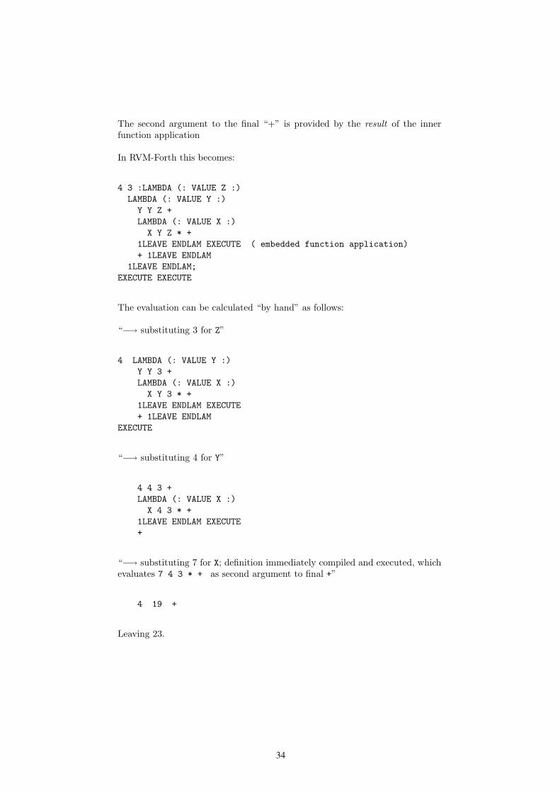
34
The second argument to the final “+” is provided by the result of the innerfunction application
In RVM-Forth this becomes:
4 3 :LAMBDA (: VALUE Z :)
LAMBDA (: VALUE Y :)
Y Y Z +
LAMBDA (: VALUE X :)
X Y Z * +
1LEAVE ENDLAM EXECUTE ( embedded function application)
+ 1LEAVE ENDLAM
1LEAVE ENDLAM;
EXECUTE EXECUTE
The evaluation can be calculated “by hand” as follows:
“−→ substituting 3 for Z”
4 LAMBDA (: VALUE Y :)
Y Y 3 +
LAMBDA (: VALUE X :)
X Y 3 * +
1LEAVE ENDLAM EXECUTE
+ 1LEAVE ENDLAM
EXECUTE
“−→ substituting 4 for Y”
4 4 3 +
LAMBDA (: VALUE X :)
X 4 3 * +
1LEAVE ENDLAM EXECUTE
+
“−→ substituting 7 for X; definition immediately compiled and executed, whichevaluates 7 4 3 * + as second argument to final +”
4 19 +
Leaving 23.

35
3.3 Stack Frame Locals and Bindings
We see that the compilation procedure for local lambda definitions differs fromnormal procedure in the way it treats local variables declared outside the scope ofthe definition. Instead of being compiled to access the value from the associatedslot in the current stack frame, a reference to this outer scope local is compiledinitially as a push of some dummy value. The location of the data field forthe push and the frame stack slot are recorded in a “bindings table”. Whenexecution reaches the local operation, these dummy values are replaced by thecurrent values of the local variables referenced.
This process is known as “closure”. The original variables cannot be assignedto from inside the resulting operation. The execution token thus produced mustremain permanently viable. Since the code that produced it could be executedmany times with different instantiations of any outer scope local variables, theexecution token cannot point to the original compiled code for the operation,but must reference some relocated code2, which embodies the particular closurethat has been formed.
This relocated code could have been kept on the heap, but as heap space tendsto be non-executable in modern configurations, it’s kept instead in a separatearea in the RVM’s code space — and managed as a stack. This simplifiesthe management considerably, and also simplifies garbage collection (using thehistory stack) on reverse execution.
3.4 Closures and Local Operations
Moving beyond a purely functional approach in which Lambda expressions haveno concept of state, we can use the technique of closures (i.e. instantiatingouter scope locals by their current value) to define words which interface todata objects such as counters, stacks, or queues. These can use named localoperations to provide persistent access to the data area created by the mainoperation.
The defining word OP encountered earlier in section 3.2 has a local analogue,also called OP, which is defined in the COMPILER wordlist and names operationslocal to an enclosing operation. The kind of local operations we now consider,however, must retain global scope, and are therefore named using the keywordFORTHOP. This is defined in the COMPILER wordlist, but is otherwise identical tothe global version of OP.
In the stack example which follows, both the stack pointer and stack dataarea are declared as instance variables; respectively, as INSTANCE-VALUE andINSTANCE-VALUE-ARRAY. These are references to reserved space on the heap,and ensure that each created stack has its own independent pointer and data.
2RVM Forth is a native code Forth which has an option to compile relocatable code, as
required here

36
: BUILD-STACK ( n --, n is size of stack, leaves tokens for push,
pop, depth and clear)
(: VALUE STACKSIZE :)
0 INSTANCE-VALUE SP ( the stack pointer, 0 for empty stack )
STACKSIZE INSTANCE-VALUE-ARRAY STACK ( the stack body )
LAMBDA ( x --, push )
SP STACKSIZE = ABORT" Stack full"
SP 1+ to SP
to << SP >> of STACK
ENDLAM FORTHOP
LAMBDA ( -- x, pop )
SP 0 = ABORT" Stack underflow"
SP of STACK SP 1- to SP
ENDLAM FORTHOP
LAMBDA ( -- n, depth of stack )
SP
ENDLAM FORTHOP
LAMBDA ( -- , clear stack)
0 to SP
ENDLAM FORTHOP
0LEAVE ;
This code leaves four execution tokens on the stack; the keyword FORTHOP picksup the names from the input stream, so they would typically be created andnamed in the same line:
4 BUILD-STACK PUSHA POPA DEPTHA CLRA
4 BUILD-STACK PUSHB POPB DEPTHB CLRB
The stacks themselves are anonymous, the named operations being the interfacefor each stack (A & B); these remain persistent, and operate on the data relatingto their own stack.
Unlike the outer scope variables referred to earlier, which were declared withVALUE in their stack frame, the stack instance variables for pointer and data can
be altered by the lambda operations.
Some sample runs and error checks:
10 PUSHA 20 PUSHA 30 PUSHA 40 PUSHA ok
DEPTHA . POPA . DEPTHA . 4 40 3 ok
5 PUSHB 15 PUSHB 25 PUSHB 35 PUSHB ok
45 PUSHB Error: PUSHB
Stack full
reported at BUILD-STACK in file lamstack.r line 6
DEPTHB . 4 ok ( error leaves data intact )
POPB . 35 ok
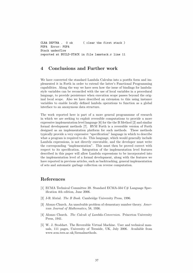
37
CLRA DEPTHA . 0 ok ( clear the first stack )
POPA Error: POPA
Stack underflow
reported at BUILD-STACK in file lamstack.r line 11
4 Conclusions and Further work
We have converted the standard Lambda Calculus into a postfix form and im-plemented it in Forth in order to extend the latter’s Functional Programmingcapabilities. Along the way we have seen how the issue of bindings for lambda-style variables can be reconciled with the use of local variables in a procedurallanguage, to provide persistence when execution scope passes beyond the orig-inal local scope. Also we have described an extension to this using instancevariables to enable locally defined lambda operations to function as a globalinterface to an anonymous data structure.
The work reported here is part of a more general programmme of researchin which we are seeking to exploit reversible computations to provide a moreexpressive implementation level language [6] for the the B Method [2] and similarformal development methods [7]. RVM Forth is a reversible version of Forthdesigned as an implementation platform for such methods. These methodstypically provide a very expressive “specification” language in which to describewhat a program is required to do. This language, which would generally includeLambda expressions, is not directly executable, and the developer must writethe corresponding “implementation”. This must then be proved correct withrespect to its specification. Integration of the implementation level featuresdescribed in this paper will allow Lambda expressions to be incorporated intothe implementation level of a formal development, along with the features wehave reported in previous articles, such as backtracking, general implementationof sets and automatic garbage collection on reverse computation.
References
[1] ECMA Technical Committee 39. Standard ECMA-334 C# Language Spec-ification 4th edition, June 2006.
[2] J-R Abrial. The B Book. Cambridge University Press, 1996.
[3] Alonzo Church. An unsolvable problem of elementary number theory. Amer-
ican Journal of Mathematics, 58, 1936.
[4] Alonzo Church. The Calculi of Lambda-Conversion. Princeton UniversityPress, 1941.
[5] W. J. Stoddart. The Reversible Virtual Machine. User and technical man-uals, 111 pages, University of Teesside, UK, July 2006. Available fromwww.scm.tees.ac.uk/formalmethods.

38
[6] W. J. Stoddart and F. Zeyda. Expression Transformers in B-GSL. In D. Bert,J. P. Bowen, S. King, and M. Walden, editors, ZB2003: Formal Specification
and Development in Z and B, volume 2651 of Lecture Notes in Computer
Science, pages 197–215. Springer, June 2003.
[7] W. J. Stoddart, F. Zeyda, and A. R. Lynas. A Design-based model ofreversible computation. In UTP’06, First International Symposium on Uni-
fying Theories of Programming, volume 4010 of Lecture Notes in Computer
Science, June 2006.
[8] J. Willcock, J. Jarvi, D. Gregor, B. Stroustrup, and A. Lumsdaine. Lambdaexpressions and closures for C++. Technical report, Open Standards Work-ing Group 22, C++, 2006.
Appendix: A more Detailed View of the Implementationof Closures
When execution reaches ENDLAM, an execution token for the corresponding op-eration is left on the stack. A local variable declared before the local operationand used within it is treated in a special way. It is not possible to assign to itwithin the local operation, but it is possible utilise its current value. Instead ofbeing compiled (as would normally be the case for local variables) to access thevalue from the associated slot in the current stack frame, a reference to such an“outer scope” local is initially compiled as a push of some dummy value, andthe location of the data field for the push and the frame stack slot associatedwith the variable are recorded in a “bindings table”. When execution reachesthe local operation these dummy values are replaced by the current values ofthe local variables in question; this process is known as “closure”.
The execution token produced in this way must remain permanently viable.Since the code that produced it could be executed many times with differentinstantiations of any outer scope local variables, the execution token cannotpoint to the original compiled code for the operation, but must reference somerelocated code which embodies the particular closure that has been formed. Anobvious place to hold such code would be on the heap, but since there is agrowing tendency to configure heap space as non-executable we choose to use aseparate area within the RVM’s code space. It so happens that we can managethis area as a stack rather than as a heap, and this simplifies this aspect ofour implementation considerably. The dynamic code area is managed by theANONCP pointer, code is pushed to this stack by PUSHCODE, which also primes thehistory stack so that the memory utilised will be released on reverse execution.
We have now introduced all the elements required for an implementation of clo-sures, and the next stage is to describe the form of the compiled code generatedfrom an anonymous operation, let’s say LAMBDA S ENDLAM. The compiled codeis as follows:
| jmp | offset | btp | code for S | push code addr | PLUG | XT |
| |
------------------------

39
The code begins with a jump which passes control past the code for S to codewhich pushes the address of the code for S onto the stack. This branch is followedby a pointer to the binding table for S and the code for S itself. Immediatelyfollowing the push code address, we see two compiled operations, PLUG and XT.
PLUG has signature ( xt – xt ). It takes the address of the code for S and uses thisto locate the binding table. It then writes in the actual values of any outer scopelocals used in S into the reserved slots in the code, thus forming the closure.PLUG also leaves the address of the code for S still on the stack. XT has signature( xt1 – xt2 ). It relocates the code for S to the dynamic code area and leavesits new execution address as xt2.
The bindings table used for the evaluation of a local operation S exists on theheap and records all local references in S that are declared before LAMDA, i.e.all locals declared in an outer scope. For each such reference we record in thebindings table:
• the address within s to be instantiated, held as an offset from the start ofthe operation,
• the nesting level of the LAMBDA..ENDLAM construct;
• the slot number of the local within its stack frame.
The bindings table entries follow an entry count which is held in the first cell ofthe table.
The binding table is built during the compilation of the anonymous operation’sdefinition, at which time the address of the binding-table-ptr entry for the func-tion is held on a dedicated stack. Entries may be pushed to or popped fromthis stack with >ANON and ANON>. The use of such a stack is required to supportthe compilation of nested LAMBDA .. ENDLAM structures. Space for the table isrequested by LAMBDA and the table is resized by ENDLAM.
When compilation encounters a local variable within a local operation, it mustdecide whether the instance is an outer scope local. To allow this to be donewe maintain a process value DLEVEL which holds the current nesting level ofa local operation. When a local variable is declared within a local operationits nesting level is recorded as an entry within its parameter field. When thelocal variable is subsequently encountered, its declaration time nesting level iscompared with the actual nesting level recorded in DLEVEL. If it is less the localis an outer scope local. DLEVEL also serves to record when compilation is withina local operation, and this is used to select compilation of relocatable ratherthan absolute code.

40
Typing Tools for Typeless Stack Languages
Jaanus Poial
The Estonian Information Technology Collegee-mail: [email protected]
Abstract. Many low-level runtime engines and virtual machines arestack based - instructions take parameters from the stack and leave theirresults on the stack. Stack language is a common name for several lan-guages used to program stack based (virtual) machines - like CLR, JVM,Forth, Postscript, etc. We chose the Forth language as an example torepresent the class of stack languages, partially because this language istypeless, partially because there exists a big amount of industrial legacyForth code that needs to be validated.Usually applications that take advantage of stack machines are mini-malistic and designed to run on restricted environments like electronicdevices, smartcards, embedded systems, etc. Sometimes these compo-nents are used to build safety critical systems where software errors areinadmissible. Type checking allows to locate possible errors of stack usagethat most often occur in stack language programs. Limited resources givepreference to a static solution - run-time type information is expensive tomanage and quite useless in turnkey applications. Static type checkingis based on a type system that is introduced here for originally typelessstack languages. This external type system is flexible enough to performseveral tasks. Static program analysis can be used both for finding er-rors and performing useful transformations on programs (optimization,parallelization, etc.).In this paper a type system to perform the so called must-analysis isdescribed that allows to locate the stack language code where the strongstack discipline is violated. Experimental implementation of the analysisframework is written in Java.
Keywords: Type Systems, Stack Languages, Program Analysis
1 Introduction
Program analysis became popular in the world of embedded systems and safetycritical applications where more resources are used to avoid software errors thanin usual office software business. Many run-time properties of a program can beestimated statically using some kind of abstract interpretation [1]. Good analysisproduces reasonable amount of warnings about suspicious passages in the pro-gram, so the human programmer can check these lines and make improvementsto the software.
� Supported by Estonian Science Foundation grant no. 6713

41
Unfortunately, analysis can be very resource-consuming, in some cases evensmall pieces of software embedded in some device take a lot of computing powerto analyze. Number of program states to explore grows very fast for preciseanalysis, to keep it under control some approximation is needed to glue similarstates into a single one. On the other hand, the analysis still has to producevaluable results.
The so called control flow graph of a program describes all possible executionpaths as a finite structure. The program state is coupled with the node (some-times with the edge) of the control flow graph. The typical analysis problem is“What is known about . . . in program point . . . ?”. There are two different kindsof statements: first, when a property must hold for all possible execution paths,and second, when a property may hold for some particular execution (there is noguarantee that it does not hold). Sometimes the must-analysis finds less proper-ties guaranteed than there actually exist, similarly the may-analysis sometimesfinds more properties than these that actually might hold. It is important to usesafe, conservative approximations, because a precise result in this area is usuallyhard or impossible to compute.
Classical data flow analysis concentrates on memory - program state is de-scribed via set of variables and analysis keeps track on variable usage and vari-able updates. We can find out uninitialized variables, live variables, availableexpressions, reaching definitions, very busy expressions, etc. Good introductionto program analysis is made in book [2].
In case of stack languages the memory state is a secondary issue, it is moreimportant to check the usage of stack(s). For example, a common mistake is towrite alternative program branches with different stack effects (it is not easy todiscover this bug if some branch is hardly ever executed).
In this paper we introduce some new ideas on static analysis of stacks, theseideas are partially implemented as a set of Java classes. Java is used as anavailable multi-platform tool, we intend to use the existing Java API to producesome Forth-targeted tools (like validator and editor that supports the strongstack discipline).
The formalism is mainly used to give a precise definition to the rules thatForth programmers know intuitively. On the other hand, it is a short way toexplain these more than thousand lines of code written to implement the basicoperations.
2 Typing rules
Original stack effect calculus is introduced in [3], related work by Bill Stoddartand Peter Knaggs is published in [6], few other works are referred in [5]. Fromthe viewpoint of program analysis it is important to mention an attempt toformalize multiple stack effects for control structures in [4]. This approach didnot lead to implementation of practical analysis tools, mainly because the setsof stack effects grew fast and were costly to manage. Instead of asking “Whatthis program might do?” (interesting, but costly and impracticable question) we

42
now prefer to ask ”Why this program does not do what it has to do?” (locatinga suspicious passage).
The following framework is oriented to the must-analysis. There are theoret-ical considerations to restrict ourselves to this type of analysis: the set of stackeffects as defined originally (polycyclic monoid) is a semilattice (each subset hasa greatest lower bound glb but does not necessarily have a least upper bound).Only the subset of idempotents is a lattice ( e is an idempotent iff e = e · e ).
In this paper the derivation rules are used to express the composition andglb of stack effects. There are two main constructs and one strong assumption:1) composition (multiplication) of stack effects describes a linear segment of aprogram,2) greatest lower bound of stack effects describes merging of alternative branchesof a program,3) body of a program loop is described by an idempotent stack effect (the stackstate does not change).
Let us introduce some notation for stack effects.
t, u, ... - possible types of data stack items.
t ≤ u - t is subtype of u (t is more exact) or equal to u
(subtype relation is transitive).
t ⊥ u - t and u are incompatible types.
ti - type symbol with wild-card index(wild-card index i is unique for elements of ”the same type”).
a, b, c, d, ... - type lists that represent the stack state (top right).
s = (a → b) - stack effect (a - stack state before the operation, b - after).
1 - empty effect (no inputs, no outputs), top of lattice of idempotents.
0 - zero effect (error, type conflict), bottom of lattice of idempotents.
(a → b) · (c → d) - composition of two stack effects (defined later).
x, y, ... - sequences of stack effects.
y, where uj := tk - substitution of uj to tk
(all occurrences of uj in all type lists of sequence y are replaced by tk )k is unique index over y.
(a → b) � (c → d) - glb of two stack effects (defined later).
r = �∗s - greatest idempotent r smaller or equal to s, zero is allowed( r · r = r and r � s ).
α, β, ... - sequences of operations (linear programs).
s(α) - stack effect of sequence α.

43
Rules for composition
These rules describe evaluation of sequence of stack effects. Whenever a typeclash occurs the result is zero. When two types (coming from different contexts)for the same stack item are compared the more exact type “wins” and thisinformation is spread to whole evaluated part of the sequence (denoted by x).
x · 0
0
0 · y
0
x · (a → bt) · (cu → d),where t ⊥ u
0
x · (a → b) · (→ d)
x · (a → bd)
x · (a →) · (c → d)
x · (ca → d)
x · (a → bti) · (cuj → d),where t ≤ u
x · (a → b) · (c → d),where ti := tkand uj := tk
x · (a → bti) · (cuj → d),where u ≤ t
x · (a → b) · (c → d),where ti := ukand uj := uk
Example
Let us have the following toy type system that represents a fragment of the Forthprogramming language:
a-addr < c-addr < addr < x
flag < x
char < n < x
Using these types and wild-cards we can introduce hypothetical stack effects:DUP ( x[1] -- x[1] x[1] )
DROP ( x -- )
SWAP ( x[2] x[1] -- x[1] x[2] )
ROT ( x[3] x[2] x[1] -- x[2] x[1] x[3] )
OVER ( x[2] x[1] -- x[2] x[1] x[2] )
PLUS ( x[1] x[1] -- x[1] )
polymorphic ”plus”, arguments have to have the same type
+ ( x x -- x )
@ ( a-addr -- x )
! ( x a-addr -- )
C@ ( c-addr -- char )
C! ( char c-addr -- )
DP ( -- a-addr )
0= ( n -- flag )
NOT ( x -- x )

44
Now let us apply the rules to some example programs
OVER OVER PLUS ROT ROT PLUS !
evaluates to ( a-addr[1] a-addr[1] -- )
On the other hand, the following program has type conflict in it
OVER OVER PLUS ROT ROT PLUS C!
It is suggested to play with some more examples to understand how the ruleswork (author also has an implementation for this set of stack effects).
Rules for greatest lower bound
To join the type information from different alternative branches of a programwe need an operation � of finding the least upper bound of finite set of effects.As mentioned before, this approach does not work well. Instead, we formulatea different problem - what are the weakest conditions to make all branchesequal? This problem can be solved using greatest lower bound operation �. Weapproximate the branching control structure as a whole by glb of all the branches.
s � 0
0
r � s
s � r
If there exist type lists a1, a2, a3, b1, b2, b3, c1, c2, c3 such that for all elementsof the lists these subtyping relations hold element-wise
a3 = min(a1, a2)
b3 = min(b1, b2)
c3 = min(c1, c2)
then the following rule is applicable, in all other cases the result is zero.
(c1a1 → c2b1) � (a2 → b2)
(c3a3 → c3b3)
If a set of effects has a non-zero glb r then all effects in this set ”do the samething”, r is just the most exact description of it (having longest lists and mostexact types). In case it is impossible to force effects to be comparable (in senseof finding a common predecessor for them) the glb is zero (zero is less or equalto any stack effect).
We also introduce the following notation that is useful for loops:
�∗s = s � (s · s)
The result of this operation is an idempotent element that most preciselydescribes the loop body s.

45
Example
ROT and @ from the previous example have glb
( a-addr[1] a-addr[1] a-addr[1] -- a-addr[1] a-addr[1] a-addr[1] )
C@ and @ have glb
( a-addr -- char )
Rules for control structures
In [4] we introduced some rules for may-analysis like the following (we do notreproduce all the rules here but just two most characteristic examples):
s( IF α ELSE β THEN )
[(true →) · s(α)] � [(false →) · s(β)]
s( BEGIN α WHILE β REPEAT )
�∗[s(α) · (true →) · s(β)] · s(α) · (false →)
These rules describe the semantics of control structures but are hard to usefor practical analysis. Informally, words IF and WHILE consume a Boolean flag(the top of the data stack) to decide which branch to choose, other control wordsare used as structure boundaries.
Let us introduce some new less exact rules in must-analysis style.
s( IF α ELSE β THEN )
(flag →) · [s(α) � s(β)]
s( BEGIN α WHILE β REPEAT )
�∗[s(α) · (flag →)] · �∗s(β)
These rules are quite strict about sequences α and β (violating the strongstack discipline implies the zero effect).
Rules for other Forth control structures are similar to these above.
Example
A good exercise is to think about the program:
: test IF ROT ELSE @ THEN ;
What is the right analysis for this program? Is this program correct?Hint: we already know the glb (ROT, @) from the previous example.

46
Another good example from [4] uses a while-cycle:
: test2 BEGIN SWAP OVER WHILE NOT REPEAT ;
test2 may loop forever in ”integer” world, in ”Boolean” world it is nearlyequivalent to
: test3 OR FALSE SWAP ;
3 Conclusion
Stack languages are used in embedded and safety critical system engineeringwhere the software testing often incorporates tools for program analysis. Thestack based approach induces the need for specific stack analysis methods. Type-less nature of stack languages allured to create an external type system thatforms a basis for static type checking.
The rules introduced above allow finding such conditions that guarantee cer-tain behaviour of the program when hold, but probably these conditions force toostrong stack discipline (no instructions with multiple stack effects, no brancheswith different stack effects, no loops that grow or shrink the stack). On the otherhand, pointing to the spots where this discipline is violated might help a lot. Wealready started a pilot project on implementing this analysis to validate someindustrial Forth legacy code.
References
1. Cousot P., Cousot R., “Abstract interpretation: a unified lattice model for staticanalysis of programs by construction or approximation of fixpoints,” 4th POPL, LosAngeles, CA , ACM Press, p. 238 – 252, 1977.
2. Nielson F., Nielson H.-R., Hankin C., “Principles of Program Analysis,” Springer-Verlag, 450 pp., 1999.
3. Poial J., “Algebraic Specifications of Stack Effects for Forth Programs,” 1990FORML Conference Proceedings, EuroFORML’90 Conference, Oct 12 – 14, 1990,Ampfield, Nr Romsey, Hampshire, UK, Forth Interest Group, Inc., San Jose, USA,p. 282 – 290, 1991.
4. Poial J. “Multiple Stack-effects of Forth Programs,” 1991 FORML ConferenceProceedings, euroFORML’91 Conference, Oct 11 – 13, 1991, Marianske Lazne,Czechoslovakia, Forth Interest Group, Inc., Oakland, USA, p. 400 – 406, 1992.
5. Poial J. “Stack Effect Calculus with Typed Wildcards, Polymorphism and Inheri-tance,” Proc. 18-th EuroForth Conference, Sept. 6-8, 2002, TU Wien, Vienna, Aus-tria, p. 38, 2002.
6. Bill Stoddart, Peter J. Knaggs: “Type Inference in Stack Based Languages,” FormalAspects of Computing 5(4): 289-298 (1993).

47
A Portable C Function Call Interface
M. Anton Ertl∗
TU Wien
Abstract
Many Forth systems provide means to call C func-tions, but these interfaces are not designed to beportable between platforms: A call to a C libraryfunction that works on one platform may fail onthe next platform, because the parameter and re-turn value types of the C function may be different.In this paper, we present an interface that avoidsthis problem: In particular, the actual calls can bemade platform-independent; a part of the declara-tions is platform-dependent, but can be generatedautomatically from C .h-files.
1 Introduction
Many operating system and library calls have theirinterfaces specified as C prototypes and are calledusing C calling conventions. As a result, C has be-come a kind of lingua franca when interfacing withother languages; other languages generally interfaceto C, and “foreign function call” libraries like ffcalland libffi are actually only designed for interfacingwith C.
This paper discusses the design of a C interfacefor Forth. The main goals of this interface are:
Portability of Forth code It should be possibleto write Forth code with calls to C such thatit works unchanged across different platforms.The portability of the C function declarationswould also be nice, but may only be partiallyachievable, as we will see.
Programmer convenience It should be easy tocall the C functions using the existing docu-mentation for them. The need for declaring Cfunctions should be eliminated if possible.
Avoid losing bits During conversions betweenForth and C types, bits should only be cut offin places where the programmer has some con-trol over what these bits are.
Full domain Allow using all possible values as ar-guments to functions. This goal conflicts withthe no-bit-loss goal.
∗Correspondence Address: Institut fur Computer-sprachen, Technische Universitat Wien, Argentinierstraße 8,A-1040 Wien, Austria; [email protected]
Many Forth systems already have a C call inter-face. However, they all fail the portability goal.Indeed, many of the interfaces contain artifacts likethe reversal of the arguments that are specific tothe platform and the Forth system involved.
This paper does not deal with access to Cstructs, unions or memory accesses to C types.In addition to some of the problems discussed here,these issues also pose additional problems, and re-quire additional effort to solve them.
2 Problems and choices
This section discusses the problems that we en-counter when we design a C call interface, and out-lines some of the design decisions. Our actual inter-face is presented in Section 3. If the present sectionappears to be complicated and lengthy, this is dueto the complex subject matter. Feel free to skip toSection 3, and only read this section to learn aboutthe reasons for this design.
2.1 Parameter order
For user convenience, the parameter order is thesame as in the C code and (more importantly) thedocumentation of the C function. I.e., the right-most parameter in C is on top of its stack in Forth,and the leftmost parameter deepest.
Some existing implementations use the reverse or-der (leftmost parameter on top of stack), becausethat is easier to implement for their systems on theIA-32 architecture (where C passes parameters onthe native stack, with the leftmost parameter ontop).
However, the reverse order is inconvenient for theusers, and error-prone. Typically, neither the nor-mal nor the reverse order are what a Forth pro-grammer would have designed for best use in Forth,so some stack juggling is often necessary; perform-ing this stack juggling while mentally reversing theorder of parameters given in the documentation ishard and frequently leads to errors.
Also, all recent calling conventions pass the firstfew parameters in registers, including the callingconventions used for Unix and Windows on theAMD64 architecture, which will gradually replace

48
Ertl A Portable C Function Call Interface
the IA-32 architecture and its stack-based callingconvention in the next years.
Finally, the implementation benefits of the re-verse order are not just restricted to an obsoles-cent architecture, but also to a specific design ofthe Forth system: It requires that stack items arekept in memory, with the data stack pointer be-ing esp, and that floating-point values are kept onthe data stack. Sophisticated native-code compilerskeep stack items in registers, and less sophisticatedsystems like Gforth do not use esp for the datastack pointer. And nearly all Forth systems use aseparate floating-point stack.
2.2 Types
The main problem with the calling C functions is:Which Forth types should we pass for various pa-rameters, and what type should we expect as returnvalue?
A simple approach would be to let all C integerand pointer types correspond to Forth cells and allC floating-point types to Forth floats, for both pa-rameters and return values. This would satisfy theportability and convenience goals.
Unfortunately, some C integer types are largerthan a Forth cell on some platforms; e.g., off t maybe 64 bits wide even on 32-bit platforms. Considera call to this C function:
off_t lseek(int fd, off_t offset,
int whence);
If we pass a cell for the offset parameter, we arenot able to pass all the possible offsets that lseek
can take, so we miss the full-domain goal. What’sworse, the result of the function is truncated to fitinto a cell, so we lose bits, contrary to our goal.
So we might actually prefer to call the C functionlseek with the following stack effect:
( n-fd d-offset n-whence -- d )
Bit loss vs. full domain
When we call lseek, the d-offset argument may betoo large (e.g., on a 64-bit system, where d is 128bits and off t 64 bits; or on a 32-bit system with a32-bit off t), and may be truncated on passing it tolseek, losing bits. This is the conflict between thefull-domain goal and the loss-avoiding goal. How-ever, in this case the problem is not that bad, be-cause the programmer has some control over thesituation; e.g., he will typically pass an offset thatcomes from an earlier call to lseek, or use a small(constant) offset that is known not to be damagedby truncation on any platform.1
1It might still be a good idea to have an (optional) run-time check that the truncation really loses only redundantbits.
So, in general, for functions we call, we usuallywant to have a Forth type for the arguments thatis at least as big as the C type (the full-domaintrumps bit-loss here); for the return value, we wanta Forth type that it at least as big as the C type,to avoid bit-loss.
For callbacks (Forth words that we pass to C asC function pointers and that the C code then calls),we want to have the Forth types for the argumentsat least as big as the C type to avoid bit-loss. Forthe return value, we again want to provide a typeat least as big as the C type to be able to returnall values out of the codomain of the function (andavoiding the bit-loss is again the responsibility ofthe programmer).
So, in all cases we want a Forth type that is atleast as big as the C type. A way to ensure thatthis is as often the case as possible would be to usedouble-cells for integer types in all places. However,that approach conflicts with the convenience goal.Actually, most C types fit into a single cell on all32-bit and larger platforms2, and there are only few,such as off t, that are larger on some platform. Soactually single cells should be the usual case, anddouble cells the exception.
You may wonder where the asymmetry betweenForth and C types comes from. It comes from thesituation for which we are designing: We have abunch of independently developed C functions thatare called from a Forth program that is designed tocall these C functions; and for callbacks, the wordsthat are called back are designed to be called backfrom these independently developed C functions. Ifwe designed an interface for calling independentlydeveloped Forth code from (dependent) C code, wewould use C types that are at least as big as Forthtypes.
2.3 Determining the Forth type
Can we determine the Forth type of a parameterfrom the C type?
We cannot determine it from the basic C type,because the basic type of the parameter might bedifferent on different platforms. E.g., off t is nota basic C type; it is usually mapped to long orlong long. If we use a single cell for long anda double cell for long long then we would get dif-ferent stack effects for lseek on different platforms,breaking portability. This approach is implementedin Gforth’s current C interface, and it is broken;fortunately parameters that may be long long arerare, so this problem is rare.
Can we determine it from the derived C type,e.g., off t? In principle this is a good idea. It
2We can restrict our view to such big platforms in manycases, because the library we want to call (e.g. OpenGL)does not exist on smaller platforms

49
Ertl A Portable C Function Call Interface
certainly can be used as a guideline when decidingwhich Forth types should be used when the pro-grammer declares the Forth type manually, as inour interface below.
One might also consider to generate the Forthtype automatically from the C prototype infor-mation (from the .h-files) and a table of C-to-Forth type mappings. However, while this strategywould work in most cases, it would not be entirelyportable, because the prototypes in the .h-files arenot necessarily the same on all platforms. E.g., onsome old Unix versions the .h-files probably containlong in place of off t, and that would typically bemapped to a single cell (whereas off t would typi-cally be mapped to a double cell).
The reason why such differences in .h files arenot a problem for C is that C performs automaticconversion between different integer types. The rea-son that they would be problems for Forth is thatForth requires explicit conversion between some in-teger types (in particular, between single-cell anddouble-cell types).
Floating point
For floating-point parameters, the situation is muchsimpler: We only have one Forth on-stack floating-point type, so we have to convert every C type tothat, and have to convert that to every C floating-point type. There may be some bit loss involved, sothe programmer should know what he is doing. Thebit loss will usually occur in the form of rounding,which will be acceptable in many situations, butmay lead to hard-to-find errors in other cases.
C performs automatic type conversion betweeninteger and floating-point types, so in theory a givenparameter might be an integer type on one plat-form and a floating-point type on another platform.However, this does not happen in practice.
Addresses/Pointers
In this paper we assume that C pointers are repre-sented as simple flat addresses. There may be someplatforms around where this is not the case, but wefeel that such platforms are not worth catering for,because:
• These platforms are relatively exotic, and itis not clear that ANS Forth systems exist forthem at all, much less that they would want touse a portable Forth-to-C interface.
• Catering for them would probably complicatethe interface significantly.
• Many programmers would probably make mis-takes in using such a more complicated inter-face without noticing (because the result would
run in a flat-address system), resulting in pro-grams that don’t port to non-flat machines de-spite the interface complications.
Moreover, we could not cater for such platforms,because we do not have enough experience with awide-enough range of such platforms to design ageneral way of dealing with them.
Pointers necessarily always fit into a cell (sinceaddresses fit into a cell), so the type problem istrivial for passing and returning pointers: just usea cell for every pointer.
However, there is a problem in what can be donewith pointers. We cannot easily fetch the data theyare pointing to or store data there, because we don’tknow how to access it. We leave this memory accessproblem to a future paper.
Still, we can do something useful with such point-ers: we can pass them to other C functions; E.g.,that is the only use that even C programmers makeof some pointer types, such as FILE *.
Structs/Unions
In C you can pass structs and unions as parametersto a function, and the function can return a structor union. We do not attack this problem in thispaper.
Fortunately, the library functions I have comeacross usually do not make use of this feature of theC language, but prefer to pass pointers to structsrather than pass structs by value. However, this isnot necessarily the case for all libraries.
Varargs
Some C functions (e.g., printf) can be called atdifferent places with different numbers and typesof parameters (varargs functions). The Forth sys-tem does not know how many of the values on thestacks are intended to be arguments to the C func-tion, which of the values on the stacks correspond towhich C type, etc. Therefore, the Forth program-mer has to make the Forth and C types used in theconcrete call explicit.
This can be done by putting that informationnear the call (probably right before it).
Another option would be to declare several Forthwords (with different names) for the C function,each with a different parameter pattern, and thenuse the right name for the desired parameter pat-tern in the call.
2.4 Case sensitivity
Another potential problem is that C names arematched case sensitively, whereas in Forth names
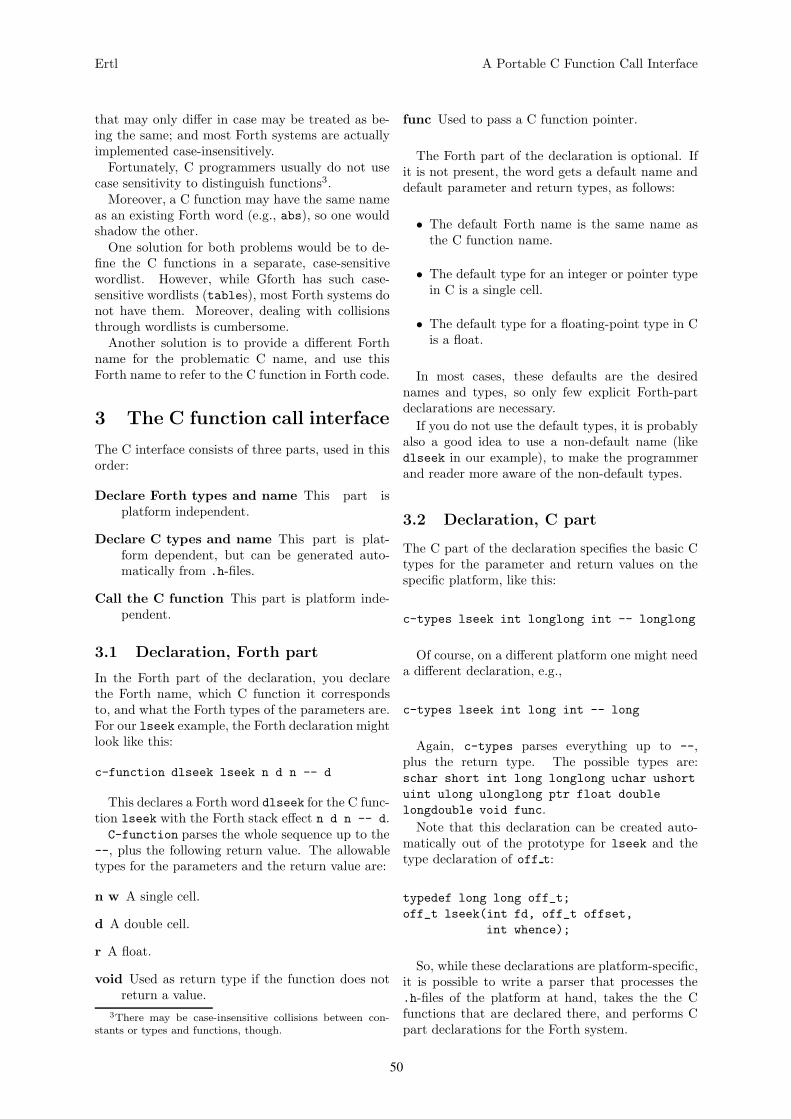
50
Ertl A Portable C Function Call Interface
that may only differ in case may be treated as be-ing the same; and most Forth systems are actuallyimplemented case-insensitively.
Fortunately, C programmers usually do not usecase sensitivity to distinguish functions3.
Moreover, a C function may have the same nameas an existing Forth word (e.g., abs), so one wouldshadow the other.
One solution for both problems would be to de-fine the C functions in a separate, case-sensitivewordlist. However, while Gforth has such case-sensitive wordlists (tables), most Forth systems donot have them. Moreover, dealing with collisionsthrough wordlists is cumbersome.
Another solution is to provide a different Forthname for the problematic C name, and use thisForth name to refer to the C function in Forth code.
3 The C function call interface
The C interface consists of three parts, used in thisorder:
Declare Forth types and name This part isplatform independent.
Declare C types and name This part is plat-form dependent, but can be generated auto-matically from .h-files.
Call the C function This part is platform inde-pendent.
3.1 Declaration, Forth part
In the Forth part of the declaration, you declarethe Forth name, which C function it correspondsto, and what the Forth types of the parameters are.For our lseek example, the Forth declaration mightlook like this:
c-function dlseek lseek n d n -- d
This declares a Forth word dlseek for the C func-tion lseek with the Forth stack effect n d n -- d.C-function parses the whole sequence up to the
--, plus the following return value. The allowabletypes for the parameters and the return value are:
n w A single cell.
d A double cell.
r A float.
void Used as return type if the function does notreturn a value.
3There may be case-insensitive collisions between con-stants or types and functions, though.
func Used to pass a C function pointer.
The Forth part of the declaration is optional. Ifit is not present, the word gets a default name anddefault parameter and return types, as follows:
• The default Forth name is the same name asthe C function name.
• The default type for an integer or pointer typein C is a single cell.
• The default type for a floating-point type in Cis a float.
In most cases, these defaults are the desirednames and types, so only few explicit Forth-partdeclarations are necessary.
If you do not use the default types, it is probablyalso a good idea to use a non-default name (likedlseek in our example), to make the programmerand reader more aware of the non-default types.
3.2 Declaration, C part
The C part of the declaration specifies the basic Ctypes for the parameter and return values on thespecific platform, like this:
c-types lseek int longlong int -- longlong
Of course, on a different platform one might needa different declaration, e.g.,
c-types lseek int long int -- long
Again, c-types parses everything up to --,plus the return type. The possible types are:schar short int long longlong uchar ushort
uint ulong ulonglong ptr float double
longdouble void func.
Note that this declaration can be created auto-matically out of the prototype for lseek and thetype declaration of off t:
typedef long long off_t;
off_t lseek(int fd, off_t offset,
int whence);
So, while these declarations are platform-specific,it is possible to write a parser that processes the.h-files of the platform at hand, takes the the Cfunctions that are declared there, and performs Cpart declarations for the Forth system.

51
Ertl A Portable C Function Call Interface
3.3 Calling the C function
Once a C function is declared, calling it works justlike with any other Forth word. E.g., for our dlseeka call might look like this4:
fd @ 0. SEEK_SET dlseek -1. d= if
... \ error handling
then
3.4 Varargs
Functions with variable numbers or types of argu-ments can be handled by declaring each argumentpattern separately:
c-function sn-printf printf w n -- n
c-types printf ptr long -- int
c-function sr-printf printf w r -- n
c-types printf ptr double -- n
s\" %ld\0" drop 20 sn-printf .
s\" %f\0" drop 2.5e sr-printf .
3.5 Callbacks
Consider the ANSI C function qsort:
void qsort(void *base, size_t nmemb,
size_t size,
int(*compar)(const void *,
const void *));
When you call it, you have to pass a C functionpointer for the last argument. You may want tolet qsort call a Forth word through that functionpointer (a callback); then you have to provide a Cfunction pointer for the Forth word. An example ofsuch a word (useful with qsort) would be:
: n-compare ( addr1 addr2 -- n )
@ swap @ swap - ;
Ideally we would like to call qsort like this:
: sort-cells ( addr u -- )
1 cells [’] n-compare qsort ;
However, a Forth execution token is not a C func-tion pointer, and qsort would not know how to ex-ecute it, so we have to get a little more involved.First we define a word compar for the kind of func-tion pointers that qsort wants, as usual in twoparts:
4Of course, there is still the question of where theSEEK SET is coming from; this is a constant with a platform-specific value, and would ideally also be created by our .h-fileprocessor.
c-function-ptr compar w w -- n
c-function-ptr-types compar ptr ptr -- int
The resulting compar is a defining word for cre-ating specific function pointers5, like this:
[’] n-compare compar fptr-n-compare
And now you can use that for calling qsort:
: sort-cells ( addr u -- )
1 cells fptr-n-compare qsort ;
4 Status
This C interface is currently just a paper design, butits implementation is planned for the near future.
5 Conclusion
Designing a C interface that allows platform-independent calls to C functions, is convenient toprogram, and has some other nice properties poses anumber of subproblems, in particular the mismatchbetween the type systems of Forth and the C. In thispaper we discuss these problems and present a solu-tion: The declartation of parameter types is dividedinto: a platform-independent Forth-type part, withdefaults that make most such declarations unnec-essary; and a platform-dependent C-type part thatcan be generated out of C’s .h-files. The main partof the Forth code, that part that contains the callsto C, is platform-independent.
Acknowledgments
I thank Sergey N. Baranov for his helpful commentson a draft version of the paper.
5An alternative would have been to make compar just aconversion word that would typically be used with constant,but that might encourage the users to call it several timeswith the same execution token, and that might cost memoryevery time.

52
������������ � ������������
��
�������
����������
��� ���
� ��� ������������������������������� ����� ���� ����� ��
������������������� ������ ����� ��� ����������� ���� ��!�������������
���������� ���"����������� � ���#�����$ ���!��������� �� ����#�� ����
�� �������������������� ������� �����"������������������������
� ��� �� �����%���������&��� ��� �� ����#��������������� �� �� �����
�������'�#�#����������� �� ����(�����
�����������)������*�+����,�$�+�"�
,�������+��� ������� ���
-� ��.&/��0��� �1�� ���*��� �
2���&�&1����3��� ���������
324�567�-�8�
"����9..�:4;4�5<;=;=
��>��9..�:4;4�5<;:<?
+������@A������������'

53
�������� ��
� ��� ���������������������������� ������ �#������������������� ���
�> ��� ���� ���� ��� �������� �������"������� ��������������� ���������
�� ����� ����������������������� ���������������������$ �������#�����
���� ��� ����������������&���$���"3+�����BC���CC7��$ ������������
������ ��� ������������� �����������#�������!��������$ ����� ���
��������� ������� �����%� ����������� � ���#��������� ���������� �D�
�� �� � ����� ����� �� ���#������ ���� �������������� �����>��� ������$ �
������� �� �������@�� ���#� �������� ��������������������������
���������� ������������ ��
���
��'����� ����������������$�� �����������������'����� ��� �� ������ �
� ������ ��������������� ������ ������� ������ �� ����� �����������������
� �������� � ����� ������������������� ���0������7�������������
�07����1�������� ������,������#������������>����� ����� � ��� ���
� ����� ����������%��������#� ����������������&��� ��07�����������������
"��������������07�������� ����������������������#��������������� �
�����
"���������%��������� ������ ����� ��� ��,����� ��������� �����������
��������CB)*��#��������������%������������ �������� � ���
�����������$����� ������� ��������� #��� ��������� ������� �� �
�������������� �%�������� ���������#���� ��� ���������� ����� ��� ��
,����������� �����������'���������������
3���������%������������� ������!���������>��������������
������������ ���������������������������������������������
��������� ��� �������#��������������� �������� ��������� ������������#���
������*��������������������������� ���������� ����� ������ �����
*�� �������*���������� ����������#������������������ ������� ��������� �
��� �������"���!�������� ����������� ��,����������E���& ����� ���
� ������� �� �� �� ������������� �� � ���!������ ����#������� �>���������� �
#�������� ��������������������� ���� ����>������������� � ���
������ ����#������� �'�� ���� ����� ������ ������������>��"�������� � ���
������ ��������� ���%�����������!���������� ������� �����������#�����
������������

54
$�������� ���!���������������������������>������ ���������� ��
��������� ������� ����������� ��� ��������������������� ���E&� ���F
"��������������� �����13+2+�������������!�������� ��������� ���������� �
�������� ��� �����@������ � #���������� ����������������-����
��%� ����� ����!����� ����������������������������� ����
����������
�� �� ����� ���� ����� ���� ����� �� ���������������> ��� ��� ���
� ���� ��� ��������� � �������( � ��������#�� � �����#�����F�G�������
����'� ���� ��� ������� ���
����������� ������ �� ����������������������������������� ���������������
���� ��������#��������#� ����� #������ ����������#� ������
���%����� ����� �������������#������������ �����%����� ��������� ����
������������ ��� �����1����%��������� ���� ���H�������$%�������
$ �� ���H�
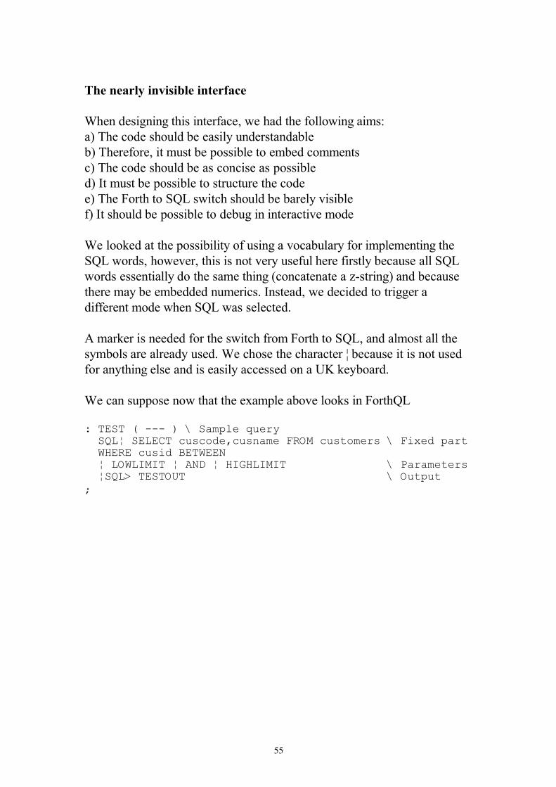
55
���������� �� � ���� ��������
1����������� ����� �� �����#������ ��� ����#�������I
���"������������������������������ ������
���"���� ������ ���� ������������� ������������� �
���"���������������������������������������
���$ ���� ������������� ��� ��� ���� �������
���"������ �� �������#� ��������������������%������
��$ �������������������� ����������� ���� �%������
1�����'���� � ������������ ��� ��������%���������� ���������� ��� ���
����#��������#�%���� �������� �%������� �������� ��� �������������������
#��������� ��������� �������� ��������� �� ����E&� ����������������
������������������������������$� �����#���������� �� ���������
�� ��� ������#�������#�������� ���
�����'������������ ��� ����#� ��� ������� �� ��������������� ����� ���
��������������������������1�������� ��������� ���J���������� ����� ������
����� �����������������������������������-8�'��������
1��������������#� �� � ����>���������%�����'������� ���
������!�"""�#�$����%&��'���(���)�*������������� �������������������$���+���%��������������������������*�����,�,��*�����*��,-��,�,� ����������$�.����������*�)�/������0�� �����$����%��
1

56
���������� ��
���'���� � ������%��#��������#�� � �������� ����I
���J���&&&E������
� �� �������������� ����������E���� ����� ���� ����������� �� ���
%���� ���� ��� ��� ����#���J����������'� ���������'������������� ��
��������%����3�#�%���� ���� ������������%����������������������� ����
� �� ���� ����
J���E����&&&E����(��
2����������������������%��� ��� ����> �J��
J���K���&&&�L�E�����M���K&&&��
C�������� ������������� ������������ � ����#������� ���!������ ����
�#���������� �>����'�#����� �����*�������� ��� �����& ������� �� � ���
����!�����#����� ����#������ ������������ � ��� ����#���#�����1���
�>��� ����� � ��� ���� ����� ���!����� ����� ���%��� �������� ����������
���������������������� ��� �� ��� ����#���#����#������������������������
� �
�� �� �� �����!����������� ���� �'��!�� �������� ���� ���>��� ���������
���� ���� ��!�� ����>��� ������������� �� �������"����� ���������� ���
��������� ��� ���� �����!�������������>��� �������� ������������ ��� �
�������� ����������� �������� ������ ����#�������� � ���� �������
�����&�� ������ �������� ������������ ���� ��� �������� ������ ���� ���
���� ����
1������������������ ����#���
J������&&&�L�E����&&&��
�������� �� ������%����� �#������� ����������� ����������� ��� ������� ���
�� ������������ ����� ������
������� ��� �#���
���&2+�-�"
#����������� ����#����� ���� �� �������� �������� �� ������ ���������

57
��������
��������#����%���� �����HB����� ��H��#� ������������� �������� ����
���*�� ������
�)�*��������2������� &��������������&�3���������������(4����5�67�*�)�/��)�"���0��8"""""""""""8"""""""""""89�2��������9�&��������98"""""""""""8"""""""""""89�:&�������9���;&���<�98"""""""""""8"""""""""""8���=�������!�>�����#<
"��� ���� ���� � ����� ��� ������ �#��������������� �����'��������� �� ���
,�����*����������*��� ��#������� �� �������#������ �,�����
�� ���������'��
�)�*�,������,������&�3����?��0���!@�;��<@ @���@ �#�*�)�
*������������������������������ N
������� ��
C������������ ������� �� ���� ��%���� ��� ������ ������������ �� ����
#�������� ��������� ����������������� ����������� ���������� �� ����
���������
58

59

60

61

62

63

64
IntellaSys Corporation 10080 N. Wolfe Road, Suite SW3-190
Cupertino, CA 95014 voice 408-446-4222
fax 408-446-5444
A 21st Century Sea Change Taking Place in Embedded Microprocessors
David Guzeman, Chief Marketing Officer, IntellaSys Corporation, Cupertino, CA
It has been 30 years since the 8048/8051
microprocessors appeared on the market
and changed the world�s view of what an
embedded microcontroller should look
like. Over the years, each new
microcontroller has tended to follow that
basic architecture, adding improvements
at each step in order to stay in step with
the increasingly demanding applications.
As long-lived and important as that
original architecture has been, it is now
time to embrace a new multicore
architecture, one designed from the
ground up to handle the applications of
the 21st century. In this white paper, we
will discuss the sea changes in
architecture design that are being driven
by demands for higher operating speeds
and lower power dissipation.
20th Century Applications
The typical application from the 20th
century used an 8-bit microcontroller � a
bit banger � that could read sensors, do a
small amount of data processing, and
then drive some I/O lines, probably
parallel, in order to send characters to a
display or record a data byte onto tape or
some other data logging device.
Additional I/O lines could scan a simple
keyboard or set of switches, and the
whole thing could be driven within time
constraints by an on-chip real time clock
that could provide precise timing
references to sync data transfers, and
perform other time-driven tasks.
These applications used only a small
amount of memory, perhaps 64 to 256
bytes of RAM, and most of that was
integrated on the chip. Although
provisions were made to access external
memory as well, this was initially a
primitive interface consisting of just an
address and data bus and relied on the
processor to read and move data in and
out of external memory under software
control.
Thus the emphasis was on controlling
I/O within tight time constraints with
very little actual data manipulation done
by the processor chip. That�s fortunate
because the processor was extremely
limited in its data processing capability
anyway and was very slow running at
clock rates of a few Megahertz. As
limited as these chips were, they were
sufficient to control countless simple
applications ranging from wall
thermostats to simple home automation
systems. In fact, at this moment I�m
typing this paper on a recently
introduced laptop that uses a derivative
of that original 8048 chip for the sole
purpose of reading keyboard clicks.
Over time, processors were introduced
that were even smaller with less

65
2
capabilities that sold for, presumably
lower prices. At the same time, others
came out that were more advanced, both
16 and 32 bit versions, and with much
faster and more sophisticated external
memory interfaces using DMA
controller circuitry. Still, the basic idea
has remained the same. One or two
processors on a chip, reading data from
input lines and sending data to output
lines, and wiggling I/O control pins as
appropriate� all to the metronome of an
external reference real time clock.
Consumer Electronics is Driving 21st Century Applications
But now the nature of the applications
has changed dramatically. In addition to
the traditional real time bit banging, a
new dimension of processing capability
has been added � the processing of
algorithms. Today the high-volume
applications are multimedia consumer
aps that range from tiny MP3 music
players to cell phones with video
capability. Moreover, the long awaited
avalanche of high-definition televisions
has begun, and along with those
televisions, consumers are suddenly
perceiving the need for home networks
that move video and music from room to
room.
Multimedia Capability
All new consumer applications have
digital data at their heart, and that
implies extensive digital signal
processing in any device that displays or
plays that data. The various file formats
for multimedia have been carefully
designed with an eye toward digital
processing by using mathematical
algorithms � Fast Fourier Transforms
(FFTs), discrete cosine transforms
(DCTs), and so forth. The high
bandwidth required to serve multimedia
applications requires that 21st century
processors have dedicated circuitry for
processing those algorithms. But at the
same time, none of the earlier
requirements for general purpose I/O
and real time clocks has gone away.
New chips must handle both!
Bitstream Orientation
Whereas earlier processors viewed
external memory as the source and
destination of applications data, modern
processors must be able to operate with
high-speed bitstreams of data arriving
from the internet, USB and 1394 cables,
as well as cable and satellite television
services. The USB 2.0 interface, now
nearly ubiquitous on consumer products
such as cameras, MP3 players, and even
cell phones, requires up to 480 mbit/sec.
The 1394 interface is commonly used in
video applications and comes in
200/400/800 mbit/sec rates. Even
gigabit Ethernet is beginning to appear
in homes with even higher data rates yet.
Today�s processors have to deal with
these data rates, all of which are
staggeringly fast by 20th
century
standards.
To make matters worse, the new High
Definition Audio-Video Network
Alliance (HANA) standard for home
networking assumes up to FOUR 1394
bitstreams that may reach 800 Mbit/sec.
And MP4 formatted data assumes
multiple bitstreams for audio and video
plus optional additional streams for
things like subtitles and still images. In
many cases, the same processor that is
decoding the MP4 bitstream from a
buffer memory must also handle the
incoming bitstream as well, so that as
many as four or five of these high-speed
bitstreams must be handled at once.

66
3
Fast External Memory Interface
With requirements for fast data are
mapped over to the external memory as
well, the days when the processor only
needed to address a few hundred bytes
of data are long over. Today, some
specialized processors aimed at video
applications, for instance, must be able
to handle 128 Mbytes of DDR SRAM
memory. While it is relatively easy to
implement larger address ranges on a
processor chip, the speed of these
memory interfaces is now critically
important. The large address space
translates into many pins on the
processor dedicated to the external
memory interface. The fact that there
are multiple bitstreams required for
many of these applications means that
there must be an easy way to quickly
switch the address bits on the memory
interface. Most modern processors use
full-blown DMA (direct memory access)
controllers for this interface � typically
three of them. Some even go the extra
step of allowing indexed addressing in
the controller. That�s convenient, for
instance, when the device is fetching
multi-byte vectors from memory.
Low Power Dissipation
Many modern consumer devices are
battery operated. The high processing
load, combined with a display, and
sometimes even a disk drive, place a
heavy load on the batteries in these
devices. As a result, power is at a
premium and the processor itself must be
capable of low-power operation to
maximize battery life. Of course, low-
power does not normally go hand-in-
hand with high processing speed, so this
represents a serious design tradeoff.
21st Century Multicore Processor Architecture
Changes in the nature of applications
clearly require corresponding changes in
the processor chip�s architecture. For
instance, the need for multimedia
capability requires special high-speed
arithmetic circuits. And the need for that
high-speed processing has led chip
designers to add core processors to the
chip so that those tasks that require real
time processing can be run on one core
while the other tasks can be run on a
second core.
Multiple Processor Cores
The approach of trying to segregate the
tasks into two groups � real time and non
real time � fails for the simple fact that
in modern applications MOST of the
tasks have a real time component to
them. Simply put, multimedia
applications are driven by high-speed
computing elements that are racing to
complete their algorithms within a tiny
slice of time before the next batch of
multimedia data arrives. Failure to do so
means there is a gap in the music or a
glitch in the video.
Recent trends have been to incorporate
one or even two DSP cores with high-
speed multiply / accumulator circuitry
Real Time Core
DSP Core
A chip with just two cores, one for real
time tasks and the other for algorithm
processing.

67
4
that keep pace with those multimedia
bitstreams. But this approach appears to
be reaching its limit whereas the demand
for additional and higher speed
bitstreams seems to know no bounds. A
much better approach is to integrate
several more core processors onto the
chip, each simpler than the complex
DSP core, but each containing a high
speed multiplier / accumulator. Properly
designed, these core processors can take
on complex algorithms by spreading the
computing load across them and sharing
the task. Of course this requires
rewriting the algorithm in a way that
facilitates this breaking up and sharing
the task but the result can be an
incredible increase in processing
capability.
Spreading the computing task in this
way has a second advantage. Whereas
chips based on DSP cores have little
flexibility, chips based on an array of
core processors can be programmed to
bring the optimum number of cores to
bear on the problem. Need more speed?
Simply assign more cores to the task.
This approach has the benefit of strong
computing power within the cores, so
that unlike the DSP which consists
mainly of high-speed arithmetic circuits,
the core processors add high-speed
conditional branching plus all the other
powers of traditional computing
elements. As a result, the multiple core
approach is extremely flexible and its
ability to solve problems is not limited to
high-speed arithmetic.
The flexibility of multicore chips means
they can be brought to bear on a wide
variety of problems by simply assigning
cores to the different tasks required.
One can be assigned to managing
external memory, perhaps eight more
could be directed to doing the FFTs to
process the multimedia algorithm, and
several more can drive the various I/O
subsystems in the application. This
sharply contrasts to the traditional
single-processor approach for handling
multiple tasks. As everyone knows, that
approach directs the single processor to
work on one task for some period of
time and then switch to another, and so
on and so on, providing the illusion of a
multi-tasking processor. In cases where
some of the tasks are I/O bound and
Video
Audio
I/O Processing
External Memory Interface
A chip with multiple cores showing how
an application can be spread across them
to maximize processing power.
ROM / RAM
A chip with 8 cores showing the bottle-neck that occurs when accessing a common shared memory.

68
5
spend significant time waiting for data to
be received, that illusion holds up pretty
well. But for tasks that are not waiting
for data, the illusion breaks down and no
one is fooled � the processor is simply
sharing its resources among the tasks
and the burden is painfully evident. The
problem is exacerbated by the context
switching time needed by the processor
to save registers and application data as
it moves from task. The larger and more
complex the processor, the greater the
context switching time and the more the
illusion of multitasking breaks down.
The multicore approach turns this on its
head by assigning one or more
processors to each task. The context
switching time is zero for the simple
reason that the individual processors
never switch tasks, and the illusion of a
multitasking chip becomes reality.
Local RAM/ROM Memory
Whenever multiple processors are
incorporated into designs, the issue of
memory access rears its ugly head. Most
multicore chip designs combine several
cores with a common memory structure.
While this simplifies the design since
each core consists of only the processor
itself, the savings is replaced with the
extremely difficult problem of sharing
the common memory among multiple
cores and arbitrating their accesses to it.
This normally involves either some sort
of arbitration network or crosspoint
switch. This approach is workable when
only 3 to 4 cores are contemplated, but
when the chip design calls for dozens, as
it does here, the complexity of sharing
memory becomes daunting. In addition,
as more and more core processors
require memory access, the sharing
becomes less and less efficient and
quickly becomes a killer bottleneck that
negates all of the processing gains that
came with multiple cores.
The solution is to replace the common,
shared memory with local memory that
is local to each core processor. In this
arrangement there is no need for
memory arbitration or crosspoint
switches because the cores are simply
accessing their own, private RAM /
ROM memory stores.
The concept of a common memory store
offers one big advantage, namely the
optimization of chip memory size by
simply allocating to each core processor
the amount of memory that core needed.
When each core has its own local
memory store, the size of that memory
will always be a compromise. If it�s too
small, the cores will be handicapped �
too large and it will be wasted and the
chip will grow larger at the cost of
efficiency.
Fortunately the size of that local memory
is easy to set. By writing code and
experimenting with typical algorithms
A chip with 24 cores, each with its own local RAM and ROM. With local memory distributed this way, there is no memory bottleneck.
CPU RAM ROM

69
6
that must be handled by the chip, it
quickly becomes clear that the
requirements fall into two sizes� 1,000
bytes and less and a much larger size�
megabytes or even hundreds of
megabytes. This second memory size
occurs when large buffers are used for
handling multimedia data, but that only
applies to a few of the cores on the chip.
Clearly, adding megabytes of local
memory to each core would be
extremely wasteful, even if it were
practical. The first memory size, 1,000
bytes, is quite practical with today�s
mainstream semiconductor processes
and is proving more than adequate as a
working size for local core memory.
The final solution obviously is to have a
relatively small local memory store for
each core, on the order of 1,000 bytes,
for code and data storage plus access to a
much larger external memory for
multimedia buffer requirements that is
used by only a handful of cores.
Communications between Cores
It is readily apparent that the idea of a
multicore chip is not that of a set of core
processor islands, each with its own set
of I/O pins standing independently from
the others. We have already described,
for instance, how compute-intensive
algorithms can be spread and shared
among multiple core processors.
Obviously that implies a level of
communication and cooperation among
the cores.
Communications between core
processors takes two forms: passing
status signals and passing blocks of data.
Conceptually there is no difference
between the two although there is a
significant difference in the
communication speed. For instance, a
status signal might be sent to a
neighboring core indicating that data is
ready for transfer, and then the cores
communicate by passing that block of
data between them. While both of these
communications approaches must be
efficient, the way that efficiency is
achieved may be completely different.
We will return to this in a moment.
As in the case of shared memory,
communications between processors can
be handled in several ways. If there are
only a couple of core processors
involved, it�s practical to provide
circuitry for each to communicate with
the others. But as the number of cores
increases into dozens, the chip area and
complexity of the communications
circuitry becomes prohibitive. Another
way to implement inter-core
communications is to limit the
communications to a smaller set of
cores, typically to just a core processor�s
nearest neighbors. This is far simpler
and very practical.
The implementation of inter-core
communications structures goes right to
Crosspoint Switch
A 16-core chip using a crosspoint switch for core-to-core communications. This quickly becomes a bottleneck with more than four or five cores.

70
7
the heart of the philosophy of bringing a
sea of processors to bear on a problem.
How are communications channels and
processes created? As computer users,
we are accustomed to letting the
computer make many of the decisions
regarding the applications we run. For
instance, when our word processor
application needs more memory as our
document grows, we rely on the
computer to find a block of memory and
assign that block to our word processor
program, a process that might entail
reassigning blocks and moving some to
disk. That process is completely
invisible to us and is done, as needed, by
the computer.
Less obvious is the fact that the memory
allocation system and even the disk
operating system were designed to make
this process efficient to drive for a
software entity, in this case, the word
processor program. The system was
designed from the very beginning with
the idea that it would be the computer
operating autonomously that would
allocate the block of memory and move
other blocks to the disk drive, as
opposed to a human being.
In the case of the multicore chip, just
how will the cores be assigned to
perform the various tasks that make up
the application? It is not going to be the
application program itself, or even some
operating system �in the sky.� The
process of assigning cores to tasks is
done by the designer / programmer who
maps the application onto the chip, not
by some development system program.
The mapping process is one of the most
basic, fundamental parts of the design
problem. To do it, the designer must ask
which tasks communicate the most data,
and then assigns adjacent cores to those
tasks to optimize the core
communications. If this core assignment
process was going to be done in some
automated fashion by the development
system, then it would be appropriate to
design an inter-core communications
system optimized for that automated
assignment process. But since it is done
by the human designer, it is much better
to use the simplest, most efficient
communications structure that simply
restricts the core communications to
nearest neighbors. Of course, it is
always possible to have cores relay data
and status signals to more remote cores,
but by restricting direct communications
to nearest neighbors, the chip design is
made much simpler and there is no real
cost to the applications designer who
was going to do the assign core tasks
anyway.
This conflict between automatic design
and design by humans targeting specific
applications will arise over and over
again. Whereas our computer functions
one moment as a word processor and the
next as a movie player or a financial
spreadsheet calculator is completely
different from how embedded processors
function. An embedded processor chip
does not switch back and forth between
being a camera and a wall thermostat,
and for that reason we should NOT
compromise chip design by burdening it
with generic do-anything, anywhere,
anytime structures like large crosspoint
switches that allow communication
between any two on-chip core
processors.
Once the decision has been made to limit
communications to nearest neighbor
cores, the communications structures
become much simpler and it is possible
to make them even more efficient.
Communications between cores now
takes place through shared registers and
there is no need for conflict resolution or
priority networks. But what is possible
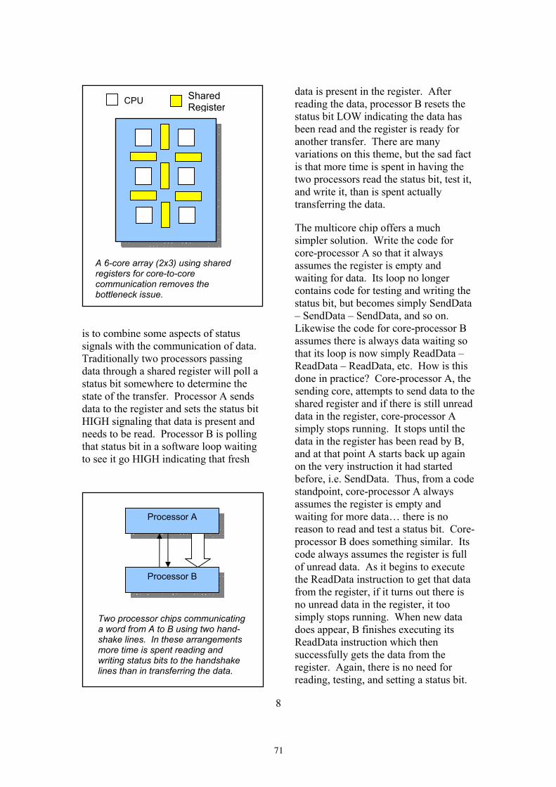
71
8
is to combine some aspects of status
signals with the communication of data.
Traditionally two processors passing
data through a shared register will poll a
status bit somewhere to determine the
state of the transfer. Processor A sends
data to the register and sets the status bit
HIGH signaling that data is present and
needs to be read. Processor B is polling
that status bit in a software loop waiting
to see it go HIGH indicating that fresh
data is present in the register. After
reading the data, processor B resets the
status bit LOW indicating the data has
been read and the register is ready for
another transfer. There are many
variations on this theme, but the sad fact
is that more time is spent in having the
two processors read the status bit, test it,
and write it, than is spent actually
transferring the data.
The multicore chip offers a much
simpler solution. Write the code for
core-processor A so that it always
assumes the register is empty and
waiting for data. Its loop no longer
contains code for testing and writing the
status bit, but becomes simply SendData
� SendData � SendData, and so on.
Likewise the code for core-processor B
assumes there is always data waiting so
that its loop is now simply ReadData �
ReadData � ReadData, etc. How is this
done in practice? Core-processor A, the
sending core, attempts to send data to the
shared register and if there is still unread
data in the register, core-processor A
simply stops running. It stops until the
data in the register has been read by B,
and at that point A starts back up again
on the very instruction it had started
before, i.e. SendData. Thus, from a code
standpoint, core-processor A always
assumes the register is empty and
waiting for more data� there is no
reason to read and test a status bit. Core-
processor B does something similar. Its
code always assumes the register is full
of unread data. As it begins to execute
the ReadData instruction to get that data
from the register, if it turns out there is
no unread data in the register, it too
simply stops running. When new data
does appear, B finishes executing its
ReadData instruction which then
successfully gets the data from the
register. Again, there is no need for
reading, testing, and setting a status bit.
CPU Shared Register
A 6-core array (2x3) using shared registers for core-to-core communication removes the bottleneck issue.
Processor A
Processor B
Two processor chips communicating a word from A to B using two hand-shake lines. In these arrangements more time is spent reading and writing status bits to the handshake lines than in transferring the data.

72
9
This technique will be unfamiliar to
most readers because it is not an option
in systems where the processors are on
different chips. The reason it works is
that, when both cores are on the same
silicon chip, there are circuit techniques
for starting and stopping core processors
that can be utilized. The key is that the
start / stop process has to be very fast �
on the order of one instruction execution
time to be really effective. But when
that can be achieved, the speedup in data
transfer between core processors is
dramatic and improves the throughput
by a factor of several times. In effect, it
completely eliminates the software
signaling between cores for many types
of data transactions.
If the core processors are designed to use
memory-mapped I/O, even more
interesting types of communication can
occur between cores. In this system, I/O
registers are treated as memory
addresses which means that the same
instructions that read and write memory
also perform I/O operations. But in the
case of multicore chips, there is a
powerful ramification of this choice for
I/O structure. Not only can the core
processor read and execute instructions
from its local ROM and RAM, it can
also read and execute instructions
presented to it on I/O ports or registers.
Now the concept of tight loops
transferring data without the need for
reading, testing, and writing status bits
becomes incredibly powerful. It allows
instruction streams to be presented to the
cores at I/O ports and executed directly
from them. And since the shared
registers between cores are essentially
the same as I/O ports, that means that
one core can send a code object to an
adjoining core processor which can
execute it directly from the shared
register with no need to actually transfer
the code to the other processors local
memory. Code objects can now be
Processor Core A (Active)
Processor Core B (Sleeping)
Core A begins the transfer process of sending a word to the sleeping core B.
Processor Core A (Sleeping)
Processor Core B (Active)
Core B completes the transfer process by waking up and accepting the data word. Meanwhile core A goes to sleep while B accepts that word.
Processor Core A (Active)
Processor Core B (Sleeping)
The process of B accepting the data word wakes up core A which begins the process again, sending the next word. B has gone back to sleep. From each processors point-of-view, the other processor is always ready to either send or receive. There is no need for handshake lines.

73
10
passed among the cores, which execute
them at the registers. The code objects
arrive at a very high-speed since each
core is essentially working entirely
within its own local address space with
no apparent time spent transferring code
instructions.
Real Time Clocks
As traditional processors have grown in
processing speed and complexity, they
have moved further and further away
from their ability to handle tasks in real
time, meaning the time to process code
is indeterminate and will vary from cycle
to cycle. This is largely due to the
introduction of increasingly larger
caches used by the processor to reduce
external memory accesses. Thus, on one
loop through the code the instructions
are all fetched externally, but on the next
they are contained within the cache. At
the same time, as processor complexity
has grown, the number of CPU registers
has increased as well. Accordingly, the
amount of time required to save the
contents of those registers during
interrupt handling has increased. All of
this makes modern processors ill-suited
for embedded applications, to say
nothing of the large memory
requirements and sheer chip cost.
Embedded processors have always
stressed the ability to handle real time
applications, to process code in a
guaranteed time slot, to handle events
and displays within a tightly controlled
(and shrinking) time allotment. Single
processor chips use a real time clock,
supplied by an external reference, to
setup and control those tasks. But what
is the ideal arrangement in a multicore
chip?
Thinking about the application as a set
of related tasks and subtasks, with cores
assigned to each, provides an answer.
Modern applications, especially those
that are multimedia intensive, are not
characterized by one or two tasks that
must be accomplished within a time slot.
Today, many if not most of the tasks
have a real time component to them.
Consequentially, one core will need to
have access to the real time clock
reference which it uses to inform the
other cores by sending status signals to
them in the form of messages, or each
core must have the capability of
accessing that reference clock directly.
Of the two, the latter is a much better
solution.
If status signals can be eliminated by
each core having its own access to the
real time clock, that combined with the
lack of need for status signals to transfer
data between cores, goes a long way to
eliminating the status signal form of
communication between cores
altogether. Notice we are not suggesting
that a system clock signal be distributed
across the cores requiring millions of
nodes to be switched synchronously to
the beat of that clock. For the real time
clock to be effective, only a handful of
nodes in each core must be switched,
and the effect on power dissipation is
negligible. A simple counter on each
node is more than sufficient to make
each node self-sufficient in terms of real
time processing.
Low Power by Design
As more and more embedded processor
chips find themselves in mobile
applications, the requirement for low
power dissipation has become critically
important. In traditional designs this is
achieved through excruciating attention
to detail, carefully determining the speed
at which each signal path must operate
and then choosing transistor sizes
appropriate to that speed. Only the

74
11
highest speed paths are implemented
with large power-hungry transistors.
But the multicore chip, with the ability
to start and stop core processors as data
is presented or denied, has a much
simpler power-saving mechanism.
Cores that are not processing data are
not running and therefore are not
dissipating any power. Cores only run
as they are needed and the turning on
and shutting off is completely automatic
and need not be invoked by the program.
The effect on power dissipation is much
larger when complete cores are shut
down than by trying to gauge and size
signal paths. In fact, this approach has a
second benefit. Because of the
automatic synchronization of data
passing between cores, there is
absolutely no reason to make the cores
themselves synchronous. That means,
there is no reason to have a central clock
to which each core must beat. Data
transfers always take place at the highest
possible speed � an external clock adds
nothing but complexity. Now the central
clock is replaced by an individual clock
for each core � a simple ring oscillator �
that runs as fast as the native speed of
the silicon allows. No central clock
means there is no giant clock tree with
millions of transistor nodes dissipating
power at each tick. Instead, the tiny
individual clock oscillators run on each
core, but only if that core is running. If
a core has been stopped because data is
either unavailable at its shared register or
has not yet been read by a neighbor, the
ring oscillator is also stopped. Clock
dissipation only occurs in running cores,
and even then these are fully
asynchronous with regard to each other
so that the power dissipation is spread
over time.
In a chip such as this, with dozens of
core processors, only a fraction of those
cores are running at any given time.
Some of these cores will be off for
significant amounts of time because the
chip is in a mode that does not run tasks
involving those cores. But even the
cores that are running are doing so in
short spurts, first turning on and
executing code as fast as silicon will
allow. Then immediately shutting back
off as they exhaust the data presented to
them or waiting for a neighbor to pick it
up and continue. In this type of
environment, we estimate only a third of
the cores would be running at any given
instant, though a few nanoseconds later,
a different group of cores would be
active, but still only about a third. This
effectively reduces the power dissipation
of the entire chip by a factor of 2/3 while
at the same time ensuring that each core
runs at the maximum possible speed of
the silicon with no compromises.
Instruction Sets
Instruction sets are mostly determined
by the register set associated with the
processor. In the case of the multicore
chip, however, the core processors are
carefully designed to provide maximum
speed with minimum size and
complexity. In other words, they are
RISC processors, that are carefully
optimized to run code using a very
simple reduced instruction set. By far
the best match of processor architecture
and processor language is to have the
processor execute instructions in some
high-level RISC language as native
machine code. This accomplishes two
things: first it packs the maximum
amount of functionality into the smallest
programs and second it maximizes the
speed of execution by eliminating the
need for intermediate translation
between high-level source code and

75
12
machine code. The first is critical in
chips with limited memory sizes and the
second is equally critical when
processing demanding multimedia
application algorithms.
That leaves the question of which high-
level language to implement as the
machine code instruction set on these
core processors, and here, the choices
are few. Most modern high-level
languages are designed to pass large
amounts of data to a set of functions and
subroutines as frames on the return
stack. This process is largely invisible to
the programmer as it is hidden behind
the machinations of the language
compiler. But that approach is wildly
inefficient for core processors of the type
we�re envisioning as the embedded chip
of the future. In this case, the processor
may be RISC but languages like C and
C++ are definitely not RISC.
Fortunately there is a language that is
optimum for these types of cores � so
optimum in fact it appears that it was
designed with multicore chips in mind.
That language is Forth.
Forth is ideal for small processor cores
for several reasons, but the first is simply
that it does not use a large number of
processor registers. The hardware
needed to implement a Forth-based
processor is minimal. And because
Forth programs are written by defining
new words and then using those to
define higher-level words yet, it is easy
to identify a small set of core words �
the kernel � that everything else is built
on, and then building those core words
into the processor as dedicated circuitry.
The result is blinding speed in a very
small core processor.
By implementing as few as 32
instructions in that core set, it is possible
to achieve the ideal RISC compromise
where the minimum instruction set
handles the majority of applications code
directly within that set and at the same
time does not pad out the set with
seldom used instructions that complicate
the circuitry and ultimately slows
execution. Clearly, an instruction set
with only 32 instructions can be
implemented in as little as five bits, but
by recognizing that some instructions
only apply in certain contexts, it�s
possible to pack multiple instructions
into a small instruction word� as many
as four instructions in an 18-bit word.
Instruction packing like this achieves an
automatic caching effect with no need
for setting up L1 and L2 caches.
Instead, each instruction fetch brings
four instructions into the core processor.
Although this built-in cache is certainly
small, it is extremely effective when the
instructions themselves take advantage
of it. For instance, micro for � next
loops can be constructed that are
contained entirely within the bounds of a
single 18-bit instruction word. These
types of constructs are ideal when
combined with the automatic status
signaling built into the I/O registers
because that means large blocks of data
can be transferred with only a single
instruction fetch. And with this sort of
instruction packing, the concept of
executing instructions being presented
on a shared I/O register from a
neighboring processor core takes on new
power because now each word appearing
in that register represents not one, but
four instructions. These types of
software / hardware structures and their
staggering impact on performance in
multicore chips are simply not available
to traditional languages � they are only
possible in an instruction set where
multiple instructions are packed within a
single word and complete loops can be
executed from within that word.

76
13
No Central Operating System
The idea of multiple cores on a single
chip is certainly not new, and in fact
there are at least a dozen already on the
market or about to be introduced. But
virtually all of these are made up of two
or four cores where those cores are large,
complex processors designed to run
desktop applications such as Windows.
There is certainly a place for these �
not in highly compact embedded
applications � but in large servers.
Such multicore processors all rely on a
central operating system to load and
direct the core processors.
This arrangement is usually typified as
SMP � Symmetric MultiProcessing �
where each of the cores is identical. To
be successful it assumes that the
software being run has been written in a
multi-threaded form. The operating
system, probably running on one of the
cores, takes that code and loads it onto
the remaining cores by separating the
code into blocks which set off the
individual threads. It loads the cores in a
way to equalize the processing load
across the cores using the threaded code
blocks as the basic code increment.
Where applications have been written in
this multithreaded format, the multicore
SMP approach works fairly well.
Of course not all software is written that
way, but even when it is not, the central
operating system can load entire
programs onto individual cores, so that
some benefit of the multiple cores can be
seen. But none of this applies in the case
of embedded processors. There are no
disk drives, no loading of cores with
tasks on-the-fly, dynamically controlled
by a central operating system. Simply
put, there is no central operating system
in an embedded processor. In the case
of multicore chips, the role of the central
operating system has been replaced with
the concept of the thoughtful
programmer.
For these kinds of chips, code is written
for specific cores on the chip. It is not
designed to run independently on any
given core, since each core is connected
to the outside world with a different set
of I/O functions. The code only makes
sense in the context of the core for which
it was written. This is not a drawback of
the approach, since the system has
already been determined to be a camera,
for instance, and not a camera one
minute and a breadmaker the next. If the
cores were to have totally different tasks
minute to minute, you could argue for
the presence of a controlling program
like a central operating system. But
since that flies in the face of the entire
concept of the embedded processor,
there is no central operating system.
This presents a slight problem. PCs, for
instance, do not simply have an
operating system, they also have a BIOS
(Basic Input Output System) the
operating system is built on. That BIOS
implements the most basic level of I/O
drivers in the system. And while the
multicore embedded processor needs no
central operating system, it still has the
need for basic input / output drivers.
And if we are going to avoid the idea of
central, shared memory we are going to
have to accept the idea of each core
processor having its own BIOS.
Since each core has its own ROM
memory, it also has the ability to have its
own BIOS. In addition to simple input /
output functions, the core processor
BIOS can have all sorts of helper
routines as well. These BIOS routines
are not simply copies, replicated in each
core�s ROM across the chip. They must
be individualized to handle the

77
14
individual personalities of the cores.
Although the cores themselves are the
same, their location within the chip array
makes them unique. Some connect to
certain types of I/O, while others
connect to other cores. Cores in the
middle of the array probably have no
external I/O at all beyond the shared
registers that are used for inter-core
communications.
Multiple I/O Interfaces
As embedded processors have moved
from the original form of the 8048/8051
to modern processors, the nature of the
I/O has changed as well. This is true
regardless of whether we�re discussing
single processors or multiple core
processors. Whereas originally simple
parallel I/O lines plus a serial interface
was sufficient, chips today must
interface with other predetermined
interfaces like USB, 1394, and SPI
(Serial Protocol Interface).
Today there are hundreds of peripheral
chips utilizing the SPI interface, and a
processor chip that provides a SPI
interface (or multiple SPI interfaces).
This opens up a world of inexpensive,
powerful peripheral functions that can be
easily incorporated into the system.
Scaleable Embedded Arrays
All of this time we�ve been discussing
multicore chips without regard for the
layout, the arrangement of the cores.
But if the cores are identical, outside of
their ROM contents that is, then the
number of cores in the array is largely
arbitrary and is set by the simple
economics of the chip size as related to
the demands of specific applications for
processing power.
Chips laid out by simply replicating
cores makes them scaleable � if there are
not enough cores to do the job, pick one
with more. Additionally, many (but not
all) of the same structures available for
inter-core communications are also
available as cores communicate from
chip to chip. Accordingly, applications
can be scaled by adding multiple chips
to increase the number of cores,
memory, and I/O.
IntellaSys specializes in innovating multicore processor solutions that target embedded applications requiring low-power operation, fast operating speed and a small footprint. For more information visit: www.intellasys.net.

78

79

80

81
82
83

84

85