Embed Size (px)
Citation preview

A PUBLICATION OF THE NATIONAL READY MIXED CONCRETE ASSOCIATION
January/February 2011ConcreteConcrete
Highlights of the 2010 NRMCA Industry
Data SurveyTake Control of Your
2011 Fuel BudgetWinter Freezes Water, Not
Your Employees’ Brains
Quality Benchmarking
Survey
2010 2010 NRMCANRMCA

502670_BASF.indd 1 10/26/10 11:01:33 PM

395767_Holcim.indd 1 10/10/08 1:56:54 PM

Experience a company with a bigger and better foundation. Expect people that deliver a higher level of service. Depend on world-class products, from the biggest mixer down to the smallest bolt. With our expanded network, we are offering more locations and more expert service, creating a convenient one-stop shop for the Ready Mix industry. All to make it easier and more affordable than ever before, as we take Ready Mix delivery to a whole new level.
GET READY TO POUR IT ON.
DEMAND THE PERFECT MIX.
Continental Mixers9797 Galveston RoadHouston, TX 77034 USA
800-231-6496www.continentalmixers.com
BOOTH #S-9433
VISIT US AT
497789_Continental.indd 1 10/25/10 11:37:45 AM

PRIMAAX® EX
PRIMAAX® EX delivers advanced suspension technologyfor rear discharge mixers with its rugged, weight efficient design.
The heavy-duty, rear air suspension system features a newrobust structural design with optimized suspension geometry
for improved durability, stability, handling and ride. With
100 percent off-highway approval, PRIMAAX EX isideal for a variety of grueling vocational and severe service applications.
Rugged, dependable and extensively tested inchallenging applications, PRIMAAX EX lays a new foundation forsuspension technology.
COMPOSILITE™ SCT13 is part of our new “Steerable Compliant” Series of lift axles. This product introduces
Hendrickson’s innovative, patent pending compliant tierod — CTR with “PerfecTrak” Technology. . . thefirst flexible tie-rod assembly and dampening system. The SCT13truck mount suspension reduces system weight up to 69 lbs. peraxle and provides a minimized package space of 22.1 inches.
The COMPOSILITE SCT product line will offer a full range of capacities including 10,000, 13,500 and 20,000-pounds to meet the industries’ demanding requirements.
www.hendrickson-intl.com
Hendrickson’s strength of innovation results in technologically advanced designs and improved durability. That’s why . . . The World Rides On Us®.
For more information about Hendrickson products, visit www.hendrickson-intl.com or call: 1-800-660-2843 – COMPOSILITE SCT13 / 1-630-910-2800 – PRIMAAX EX
COMPOSILITE™ SCT13COMPOSILITE™ SCT13
Leading innovation and improved durability
501588_Hendrickson.indd 1 11/2/10 3:35:02 PM

NEW
better together
Dramix® READY - steel fiber reinforcement
Dramix®
Bekaert Corporation - Building Products1395 S. Marietta Parkway, Bldg 500 Suite 100 Marietta, GA 30067P. 800 555 1775 - F. 770 426 [email protected]
YES! Dramix® READY is:
• The Gold medal winning aspect ratio (length / diameter) of 80
• The 100M dash winner: strong performance,
having 3325 feet of wire per cubic yard
• Replaces steel with steel and reduces cracks in your floors
• Minimum reinforcement always at the right place
• Time and money saving solution
www.bekaert.com/building
economical lightly reinforced floors
483538_Bekaert.indd 1 6/18/10 11:43:51 AM

CONCRETE in focus ı 7
f e a tu re s11 2010 NRMCA Quality Benchmarking Survey
16 Inch by Inch
19 Highlights of the 2010 NRMCA Industry Data Survey
d e p a r tm e n ts9 Truck Tracs: Take Control of Your 2011 Fuel Budget
23 Education Matters: Winter Freezes Water, Not Your Employees’ Brains
26 Advertisers’ Index/Advertiser.com
Visit our Buyers’ Guide online at NRMCA.OfficialBuyersGuide.net
Concrete infocus is published for:National Ready Mixed Concrete Association900 Spring StreetSilver Spring, Maryland 20910Phone: (301) 587-1400Fax: (301) 585-4219www.nrmca.org
President: Robert A. Garbini, P.E.
Managing Editor: Kathleen Carr-Smith
Association Editor: Frank Cavaliere
Published by:
Naylor, LLC5950 NW 1st PlaceGainesville, Florida 32607Phone: (800) 369-6220Fax: (352) 331-3525www.naylor.com
Publisher: Jill Andreu
Editor: Sean Garrity
Project Manager: Heather Ciocca
Marketing Research: Amanda Niklaus
Advertising Director: Maureen Hays
Account Representatives: Lou Brandow, Krys D’Antonio, Ryan Griffi n, Norbert Musial, Christine Ricci, Rick Sauers, Jamie Williams, Chris Zabel
Layout and Design:Emma Law
Advertising Art:Jean-Baptiste Bonnelame
©2010 Naylor, LLC. All rights reserved. The contents of this publication may not be reproduced by any means, in whole or in part, without the prior written consent of the publisher.
PUBLISHED DECEMBER 2010NRC-S0610-9979
January/February 2011, Vol. 10, No. 1
Please visit the electronic version of Concrete Infocus at http://www.nrmca.org/news/connections/ for bonus features, including Who to Call at NRMCA, Tech Talk, Quality Corner and an assessment of pervious concrete maintenance techniques.
infocusConcrete
conten ts
Cover ©www.istockphoto.com

THE LEARNING STARTS NOWTHE LEARNING STARTS NOW
Put down this magazine and flip on your computer for some free industry webcasts. They’re crammed with practical information you can use right now. Sure makes waiting for the sunny days of CONEXPO-CON/AGG 2011 a little easier.
Check out any or all of these webcasts free (each a $70 value).MARCH 22-26
LAS VEGAS USA
Co-located with Register to view whenever at
www.conexpoconagg.com/tasteof2011© 2010 Association of Equipment Manufacturers
Concrete Always Cracks Prevent callbacks by eliminating this perennial problem.
Project Management Fundamentals Become a better project manager, whether you’re a rookie or a veteran.
Paydirt: Mass Excavating Alternatives for Mass Profit Choose the right equipment to pile up profits.
Best Practices for Fleet Management Save 2% to 5% in your fleet maintenance budget with these efficiencies.
8ConExpo.indd 1 11/1/10 12:05:48 PM

CONCRETE in focus ı 9
Take Control of Your 2011 Fuel Budget
truck tracs
With the downturn in the economy, the ready mixed concrete industry is being forced to price bids competi-
tively with little room for error—any inaccuracy in your cost estimates can hurt your cash flow and earnings. And while many are diligent in capturing the cost of materials and labor in their bids, most struggle with estimating fuel costs.
As a major cost, fuel poses a unique challenge to the ready mixed concrete industry
While many fl eets track their fuel usage in miles per gallon, this does not provide a true picture of fuel usage for ready mixed concrete companies like yours. Mixer trucks spend vary-ing amounts of time at idle, mixing concrete or off -road travel. And this is before we even con-sider power-take-off (PTO) energy use. A 2006 NRMCA study found that PTO accounts for 20-25% of total fuel consumption alone.
Ready mixed concrete companies, along with other businesses, have found it extremely diffi cult to accurately pin down fuel costs. Since 1999, the average annual price movement from low to high as reported by the U.S. Dept. of Energy (DOE) is $0.7544/gallon. Even if we disregard 2008, which presented unprecedented fuel price fl uctuations, the yearly average fl uctuation is approximately $0.61 since 1999. As many know, even small fuel price increases can result in large, unbudgeted fuel cost variance.
Th ese dramatic price fl uctuations coupled with a longer construction season (from what used to be a nine month season to now 12 months) makes it even more diffi cult for you to forecast future fuel prices to accurately price a bid upfront.
With growing emerging market demand, weakened U.S. dollar, geopolitical realities of the Middle East combined with unexpected natu-ral disasters, fuel prices are anyone’s best guess and continue to expose companies to signifi cant operating risk. As a result, it’s crucial for your company to adopt a more strategic and proactive approach to protecting your fuel budgets.
Introducing fuel price protectionHistorically, most companies were not able
to hedge their fuel costs because they did not have large enough fuel budgets or the necessary in-house expertise to decipher and navigate the fuel commodities market. Th is is changing with advances in technology and fi nancial instruments giving companies of all sizes more control over their fuel budgets.
Fuel price protection off ers a new, unique approach to fuel budget control. You select a protection price that represents the most your company wants to pay for fuel. When fuel prices (as measured by an index such as the U.S. DOE national average fuel price) go above that protec-tion price, your company receives a payment equal to the diff erence. Th is allows you to accurately predict your company’s maximum fuel costs.
With this fi nancial arrangement, there is no change to how you fuel your fl eet and no pre-pur-chase of fuel. Fuel is still purchased at the pump, in bulk, or via a discount fuel card. Fuel price pro-tection is not tied to actual usage. If the predicted amount of fuel is not used, there is no cost to your company. And if fuel prices drop, you can still buy fuel at the current, lower market price.
Fuel price protection off ers some specifi c advantages to the ready mixed concrete industry:
° Increases competitive advantage: Remain profi table by locking in your project margins upfront without worrying about cost overruns due to fuel. Ultimately, this may enable you to undercut the competition with fi xed bids/contracts and gain market share.
° Helps mitigate risk: Better upfront risk plan-ning can help you cap your fi nancial exposure, prevent detrimental damage to your fuel bud-get and protect your bottom line.
° It’s proactive: Protect your most volatile expense upfront and redirect your limited resources to focus on strategic initiatives.
Why are we discussing fuel price protection now?
Since 1999, the lowest fuel prices have occurred on average within a six week timeframe—between
Fuel price protection offers a new, unique approach to fuel budget control.

10 ı JANUARY/FEBRUARY 2011
www.humboldtmfg.com1.800.544.7220
if this looks familiar……get familiar with
HUMBOLDT
492563_Humboldt.indd 1 9/15/10 10:56:50 AM
Don’t let hot water shortages slow you down, ensure your hot water supply keeps up with
YOUR demand.
To schedule an on-site plant analysis or for information contact Kemco Systems
800.633.7055
KEMCO SYSTEMS
RM99Direct Contact Water Heater
Kemco Systems is a proud memberand supporter of the NRMCA
STOP
The RM99 Direct Contact Water Heater • 99.7% fuel efficient • Instantaneous hot water • Stainless steel, non-pressurized unit • Convenient 4-point connection
LOSING BUSINESS!
254429_Kemco.indd 1 7/31/06 9:38:12 AM
three weeks before year-end and three weeks after the New Year. After that point, fuel prices typically rise and continue in a bell curve pattern reaching their peak in June and July.
If history is our guide, right now is the best time for you to cap your company’s fuel costs. By taking advantage of lower price levels, your company can continue to benefi t from low fuel prices next year and
turn one of your biggest fi nancial risks into a competitive advantage.
About PricelockPricelock, headquartered in Redwood
City, CA, is a proud member of the National Ready Mixed Concrete Association and has introduced a new way for businesses large and small to incorporate stability and pre-dictability into their fuel budgets with its fuel price protection program. Bringing together expertise in commodities, risk management and technology, Pricelock has price protected over 100 million gallons of fuel for Chrysler, Hyundai and other lead-ing businesses.
Th e Pricelock program is simple and safe: businesses get paid when fuel prices rise above their protection price. When fuel prices fall, there are no hidden costs and they continue to buy at lower fuel prices unlike fi xed price programs. With Pricelock, plans can be created in any size allowing busi-nesses to accurately estimate their fuel costs even for a specifi c project. ■
For more information, visit www.pricelock.com or call us at 650-517-5416.

CONCRETE in focus ı 11
NRMCA Quality Benchmarking SurveyIntroduction
Th e 2010 NRMCA Quality Benchmark-ing Survey was conducted in the summer of 2010. Th e need for this survey resulted from discussions within the NRMCA Research Engineering and Standards Committee and the survey questions were established by a task group of the committee. Surveys were completed by a ready mixed concrete pro-ducer company or division. Th e survey had 3 sections.• Section 1 - General company information• Section 2 - Quality indicators• Section 3 - Quality benchmarks
Th is report establishes averages and other benchmark from this survey. For this survey respondents were asked to use data from the most recent fi scal year. Respondents were asked to avoid guessing and not to respond to questions where information was not available. Th is survey is intended to pro-vide benefi ts to concrete producers in terms of industry statistics for quality initiatives. Th ere were 28 respondents to this survey from 16 companies. Some large companies submitted survey responses for several of their divisions.
Section 1 - General company information1.3 Annual Concrete Volume (cubic yards)Th e respondents to this survey produced a cumulative 21.7 million cubic yards in 2009 representing approximately 8.4% of esti-mated ready mixed concrete produced in the U.S. for that year. Th e breakdown was as follows:
Annual Concrete Volume, Number ofcubic yards Respondents≤100,000 1100,001 to 250,000 5250,001 to 500,000 6500,001 to 1 Million 121 to 3 Million 2>3 Million 2
1.4 Number of PlantsTh e respondents to this survey supplied con-crete from a total of 670 plants. Company or division size ranged from 3 to 179 plants.
1.5 Market served by companies – percent of annual productionAll responded
Percent of AnnualMarket ProductionPublic (FAA, DOT, city, county) 37Commercial 37Residential 23Other 3
Numbers represent the average value. Vol-ume for the residential market is lower than expected due to the overall drop in construc-tion in that market sector.
1.9 Are you in a weathering region requir-ing air entrained concrete?All responded
Percent ofCold Weather Region RespondentsYes 68%No 32%
Section 2 - Quality indicators2.1 Provide information on top 5 selling mixtures.
Question Average2.1a Weighted average standard deviation (SD), psi 5052.1b Weighted average Avg. strength, psi* 37732.1c Weighted average coeffi cient of variation, COV, % 10.3%2.1d Average increment, % 28.6%2.1e Number air entrained 2.4
*Even though 2.1b asked for average strength all respondents provided speci-fi ed strength. So the number reported is the weighted average specifi ed strength.
Weighted average statistics were determined by multiplying the percent volume of each mix listed and the individual mix statistic.
2.1a and as a result 2.1c had 26 respon-dents. Other questions were responded to by all 28 respondents. Among the respondents who answered 2.1a and 2.1c information was provided for 90% of the maximum possible 130 mixtures. Th e weighted average SD was 505 psi. According to ACI 214R-02, SD of 500 to 600 psi would qualify as a good stan-dard of concrete control for general construc-tion testing.
Average increment represents the incre-ment of the average strength above the speci-fi ed strength for the fi ve mixtures reported by the respondent. On average, the increment of the average strength of the mixtures over the average specifi ed strength is 28.6% (1079 psi). For mixture submittals according to ACI 318
feature
2010

12 ı JANUARY/FEBRUARY 2011
the average increment should be 1.34XSD (677 psi) over the specifi ed strength when a test record is available to calculate the SD. Th e fact that concrete producers are providing an excess of 402 psi above that is not unusual and could be due to several reasons –1. Producers are reducing their risk of fail-
ing test results compared to ACI 318’s 1% probability of strength tests failing the acceptance criteria.
2. Producers could be supplying to concrete with a minimum w/cm and/or mini-mum cementitious content, which results in a higher average strength than that required;
3. Producers are unable to use SD informa-tion in their mixture submittal, either because test record data are not available, not documented or specifi cations require designing concrete mixtures to a fi xed increment above specifi ed strength.
2.1e shows that the data provided was split equally among air entrained and non air entrained concrete mixtures. Th is question was asked because the strength variability of air entrained mixtures is typically higher.
2.2 Concrete rejected at jobsite as percent of production.Report percent based on total volume or loads. Include all rejected loads for reasons associated with quality, specifi cation or delivery require-ments, including the amount benefi cially reused. Do not include concrete returned due to ordering excess quantities. 24 responded and the average was calculated as 0.57%. Th e distribution of responses was as follows:
Percent Concrete Percent of Rejected Respondents0% 7%0.001 to 0.1% 11%0.1 to 0.49% 21%0.5% to 0.99% 7%1% 39%Did not respond 14%
Approximately 40% reported that rejected concrete is less than about 0.5% which is a very low number. Verbal estimates of returned concrete, which includes quantities returned due to excess ordered, tend to be higher, sug-gesting that a primary reason for returned quantity is based on customers ordering prac-tices rather than for quality reasons.
2.3 Cost to company to resolve customer problems, in $ per yd3 produced.
Include cost to repair, replace or mitigate hard-ened concrete issues because concrete did not meet purchaser’s or specifi cation requirements, expectation, etc. For example, if the company produced a total of 20,000 yd3 of concrete and the total cost paid for the above reasons was $20,000 the cost should be calculated and reported as $1/yd3. 23 responded and the aver-age was calculated as $0.42/yd3. Th e distribu-tion of responses was as follows:
Cost to Company. Percent of $/yd3 Respondents0 7%0.01 to 0.2 29%0.21 to 0.5 25%0.51 to 0.99 7%1 14%Did not respond 18%
2.4 Perception of company’s quality level by customer in annual quality survey (or other means)
All responded
Quality Percent of Perception RespondentsNot Applicable 50%Excellent 18%Very Good 25%Good 7%Fair 0%Poor 0%
Of the survey respondents, 50% of the companies report a quality perception that is Excellent, Very Good or Good. Th e remain-ing 50% of the respondents do not track their customers’ perception of their quality level. While most companies survey their custom-ers or otherwise attempt to annually gage their customers’ perception of the company, it is clear that such survey responses are related to delivery and other service-related issues.
It is suggested that concrete producers incorporate the above or a similar question as part of annual customer surveys or by other means. Why is the customer’s perception of company quality level important? It conveys the company’s emphasis on quality and con-tinual improvement. When customers asso-ciate quality with a ready mixed concrete producer, they are less likely to assign blame for problems and will attempt to identify other causes for those problems. Owners and design professionals will be more likely to involve the concrete producer in product require-ments in specifi cations for desired concrete
performance; or to solicit their advice when problems occur. Th e attention to quality ini-tiatives will foster increased business.
Section 3 - Quality benchmarks3.1 Does your company maintain a quality plan?All responded
Quality Percent of Plan RespondentsYes 86%No 14%
3.2 Is there a process in place to collect cus-tomer feedback regarding company quality and act on it?All responded
Customer Feedback Percent of Process RespondentsYes 68%No 32%
3.3 Total number of employees with qual-ity control/technical function, including fi eld and laboratory techniciansAll responded and the average was calculated as 1.6 employees for every 100,000 yd3 of annual production. An alternative estimate is there is one person with a quality control/technical service function for 62,500 cubic yards. Th e average for respondents below 500,000 yd3 production was 2.3 (1 person per 45,000 cubic yards) and average for respon-dents above 500,000 yd3 was 1.1 (1 person per 91,000 cubic yards). Th e distribution of responses was as follows:No. of QC/ Tech per 1 person Percent of 100,000 yd3 per, yd3 Respondents≤ 0.5 ≥ 200,000 7%0.5 to 1 199,000 to 25% 100,0001 to 2 99,000 to 39% 50,000> 2 < 50,000 29%
3.4 Number of fi eld and laboratory techniciansAll responded and the average was calculated as 1.2 for every 100,000 yd3 of annual pro-duction. Technicians are a subset of employ-ees reported in 3.3. An alternative estimate is there is one fi eld/laboratory technician for 84,000 cubic yards. Th e average for respon-dents below 500,000 yd3 production was

CONCRETE in focus ı 13
1.8 (1 technician for 56,000 cubic yards) and average for respondents above 500,000 yd3 was 0.7 (1 technician for 143,000 cubic yards). Th e distribution of responses was as follows:No. of fi eld/lab techs per 1 technician Percent of100,000 yd3 per, yd3 Respondents≤ 0.5 ≥ 200,000 21%0.5 to 1 199,000 to 36% 100,0001 to 2 99,000 to 32% 50,000 > 2 < 50,000 11%
3.5 Average volume of concrete under responsibility of one technical manager.Divide the total volume by the number of technical managers to represent an average volume for each manager’s responsibility. 26 responded and the average was calculated as one technical manager with responsibility for 326,000 yd3. Th e average for respondents with production less than 500,000 yd3 production was one technical manager with responsibility for 179,000 yd3 and average for respondents with production above 500,000 yd3 was one individual for 434,000 yd3. Th e distribution of responses was as follows:Average volume under responsibility of Percent of1 technical manager, yd3 Respondents≤100,000 11%100,000 to 200,000 21%200,000 to 350,000 25%350,000 to 600,000 25%>600,000 11%Did not respond 7%
3.6 Percent of quality control/technical employees above technician level with NRMCA Concrete Technologist Level 2 certifi cation or equivalentAll respondedPercent of Employees Percent ofwith NRMCA Level 2 Respondents< 20% 32%20% to 50% 32%>50% 36%
3.7 Quality control costs, in terms of $ / average sales price of cubic yard.Include lab costs and all quality control staff salaries, including corporate level technical managers. Do not include back charges or penalties. 24 responded and the average was calculated as $1.14/yd3. Th e breakdown was as follows:
QC Cost to Company. Percent of $/yd3 Respondents0 to 0.75 7%0.76 to 1.25 50%1.26 to 1.75 21%>1.75 7%Did not respond 14%
3.8 Percent of production facilities that are inspected or certifi ed - NRMCA or state highway departmentAll respondedPercent of Percent of Production Facilities Respondents< 20% 4%20% to 50% 7%>50% 89%
3.9 Frequency of verifying accuracy of measuring devices - scales, water meters admixture dispensers, etc. (calibration or internal checks) per plantAll respondedFrequency of Percent ofVerifying Accuracy Respondents6 months or less 75%More than 6 months 25%
3.10 Frequency at which mixers are inspect-ed for wear and build-up per plantAll respondedFrequency of Percent ofVerifying Accuracy Respondents6 months or less 86%Annually 14%
3.11 Frequency at which technical manag-ers review batch records and mixture per-formance per plantAll respondedFrequency of Percent ofVerifying Accuracy Respondents< 1 month 36%1 to 6 months 61%7 to 12 months 0%> 12 months 4%
3.12 Number of company laboratory facili-ties possessing at least one strength testing machineAll responded and the average was calculat-ed as 0.34 for every 100,000 yd3 of annual production. An alternative estimate is there is one laboratory with at least one strength testing machine for 295,000 cubic yards. Th e average for respondents with production below 500,000 yd3 production was 0.40
(one lab for 250,000 cubic yards) and aver-age for respondents with production above 500,000 yd3 was 0.30 (one lab for 330,000 cubic yards).No. of labs Concrete per 100,000 volume per Percent ofyd3 one lab, yd3 RespondentsNone 11%≤ 0.2 ≥ 500,000 14%0.201 to 0.4 499,000 46% to 250,000 0.402 to 0.6 249,000 to 14% 167,000 >0.6 < 167,000 14%
3.13 Number of laboratory facilities that are inspected and participate in profi ciency sample (CCRL) or regional round robin testing27 responded
Th is question assumes the existence of a lab that would conform to some of the require-ments of ASTM C1077 and will have a higher level of testing capabilities than lab facilities listed in 3.12. Of the respondents, 19 did not have a lab in this category.Annual Concrete Number ofVolume, Number of respondentscubic yards Respondents with labs*≤100,000 1 0100,001 to 250,000 5 0250,001 to 500,000 6 2500,001 to 1 million 12 31 to 3 million 2 2**>3 million 2 2***
*Unless otherwise noted, respondents reports one lab in this question.
**One respondent reports 6 labs***Both respondents report 2 labs each.
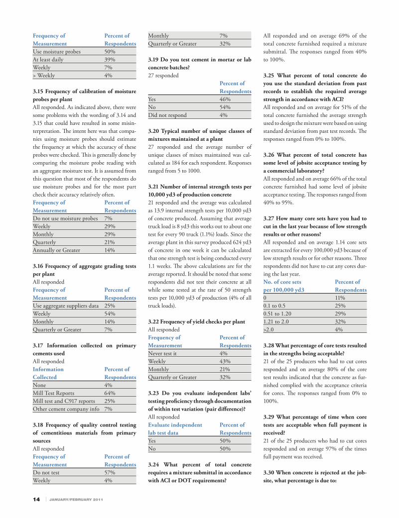
3.14 Frequency of measuring aggregate moisture contentAll responded. Th is question resulted in some misinterpretation. Respondents could make only one of the four choices listed below. It is likely that some respondents have some of their plants with moisture probes installed and selected that choice. Th e intent of the question was to gain an idea of the fre-quency at which aggregate moisture is mea-sured. Th e percentage of respondents that indicate use of moisture probes is not in line with the respondents in 3.15 that indicate that they did not use the probes. In general, it appears that the respondents do pay close attention to measuring the moisture content of aggregates.
14 ı JANUARY/FEBRUARY 2011
Frequency of Percent of Measurement RespondentsUse moisture probes 50%At least daily 39%Weekly 7%> Weekly 4%
3.15 Frequency of calibration of moisture probes per plantAll responded. As indicated above, there were some problems with the wording of 3.14 and 3.15 that could have resulted in some misin-terpretation. Th e intent here was that compa-nies using moisture probes should estimate the frequency at which the accuracy of these probes were checked. Th is is generally done by comparing the moisture probe reading with an aggregate moisture test. It is assumed from this question that most of the respondents do use moisture probes and for the most part check their accuracy relatively often.Frequency of Percent of Measurement RespondentsDo not use moisture probes 7%Weekly 29%Monthly 29%Quarterly 21%Annually or Greater 14%
3.16 Frequency of aggregate grading tests per plantAll respondedFrequency of Percent ofMeasurement RespondentsUse aggregate suppliers data 25%Weekly 54%Monthly 14%Quarterly or Greater 7%
3.17 Information collected on primary cements usedAll respondedInformation Percent ofCollected RespondentsNone 4%Mill Test Reports 64%Mill test and C917 reports 25%Other cement company info 7%
3.18 Frequency of quality control testing of cementitious materials from primary sourcesAll respondedFrequency of Percent of Measurement RespondentsDo not test 57%Weekly 4%
Monthly 7%Quarterly or Greater 32%
3.19 Do you test cement in mortar or lab concrete batches?27 responded Percent of RespondentsYes 46%No 54%Did not respond 4%
3.20 Typical number of unique classes of mixtures maintained at a plant27 responded and the average number of unique classes of mixes maintained was cal-culated as 184 for each respondent. Responses ranged from 5 to 1000.
3.21 Number of internal strength tests per 10,000 yd3 of production concrete21 responded and the average was calculated as 13.9 internal strength tests per 10,000 yd3 of concrete produced. Assuming that average truck load is 8 yd3 this works out to about one test for every 90 truck (1.1%) loads. Since the average plant in this survey produced 624 yd3 of concrete in one week it can be calculated that one strength test is being conducted every 1.1 weeks. Th e above calculations are for the average reported. It should be noted that some respondents did not test their concrete at all while some tested at the rate of 50 strength tests per 10,000 yd3 of production (4% of all truck loads).
3.22 Frequency of yield checks per plantAll respondedFrequency of Percent ofMeasurement RespondentsNever test it 4%Weekly 43%Monthly 21%Quarterly or Greater 32%
3.23 Do you evaluate independent labs’ testing profi ciency through documentation of within test variation (pair diff erence)?All respondedEvaluate independent Percent oflab test data RespondentsYes 50%No 50%
3.24 What percent of total concrete requires a mixture submittal in accordance with ACI or DOT requirements?
All responded and on average 69% of the total concrete furnished required a mixture submittal. Th e responses ranged from 40% to 100%.
3.25 What percent of total concrete do you use the standard deviation from past records to establish the required average strength in accordance with ACI?All responded and on average for 51% of the total concrete furnished the average strength used to design the mixture were based on using standard deviation from past test records. Th e responses ranged from 0% to 100%.
3.26 What percent of total concrete has some level of jobsite acceptance testing by a commercial laboratory?All responded and on average 66% of the total concrete furnished had some level of jobsite acceptance testing. Th e responses ranged from 40% to 95%.
3.27 How many core sets have you had to cut in the last year because of low strength results or other reasons?All responded and on average 1.14 core sets are extracted for every 100,000 yd3 because of low strength results or for other reasons. Th ree respondents did not have to cut any cores dur-ing the last year.No. of core sets Percent ofper 100,000 yd3 Respondents0 11%0.1 to 0.5 25%0.51 to 1.20 29%1.21 to 2.0 32%>2.0 4%
3.28 What percentage of core tests resulted in the strengths being acceptable?21 of the 25 producers who had to cut cores responded and on average 80% of the core test results indicated that the concrete as fur-nished complied with the acceptance criteria for cores. Th e responses ranged from 0% to 100%.
3.29 What percentage of time when core tests are acceptable when full payment is received?21 of the 25 producers who had to cut cores responded and on average 97% of the times full payment was received.
3.30 When concrete is rejected at the job-site, what percentage is due to:

CONCRETE in focus ı 15498524_Solomon.indd 1 10/4/10 4:15:32 PM
All responded and the distribution of respons-es is as follows: Percent of Cause RespondentsSlump 43%Air content 32%Delivery time or exceeding revolution limits 14%Other 8%
Some reasons listed in the other category by respondents are• unit weight,• color,• temperature,• plant/mechanical breakdown,• mixture being too rocky or too sandy
(contamination) or pumpability (or lack thereof),
• dispatch order entry error,• wrong mix,• missing fi bers,• wrong delivery time,• truck malfunction,• operator error,• cement content out of tolerance
3.31 What percentage of call backs due to hardened concrete are related to:All responded and the breakdown is as follows: Percent of Cause RespondentsCracking 46%Strength 21%Scaling 20%Other 12%
Some reasons listed in the other category by respondents are:• delamination, • color,• set time, • dusting,• workmanship, • fi nishing errors,• aesthetics, • contamination,• soft particles, • fi nishability,• yields, • workmanship
of contractor.
ConclusionTh is was the fi rst survey on quality ini-
tiatives conducted by NRMCA under the direction of the Research Engineering and Standards Committee. Th e goal of the
survey is to evaluate typical resources and benchmarks that support quality initiatives in ready mixed concrete companies. Con-sidering that this survey represents informa-tion when the industry was operating during a period of downturn in the construction industry, it may not represent benchmark values as one might expect during “normal” times. Th e goal of this survey is to measure quality benchmarks on company resources assigned for quality management systems and to provide for continual improvement in the industry. NRMCA expects to conduct this survey once every two years. Questions will be improved for clarity and other questions might be developed in future surveys.
Th e following members of the Task Group that helped develop the survey are gratefully acknowledged:
Mark Williams, Williams Concrete Inc.Steve Ragan, Concrete Supply CompanyJeff O’Leary, Vulcan Materials CompanyChris Wolf, Shelby MaterialsJohn Vaughan, Irving MaterialsGodwin Amekuedi, ARGOS USAMike Epifano, Cemex ■

16 ı JANUARY/FEBRUARY 2011
Inch by Inch(Reprise)
Introduction by Amy Miller, National Resource Director, NRMCA
Article by Randell Riley, P.E., Executive Director/Engineer for Illinois Chapter of ACPA and consultant to Illinois Ready Mixed Concrete Association
IntroductionIn the “old days”
(prior to 2008) we were forced to sell concrete park-ing lots based primarily on long-term costs savings, or so we thought. We would perform life cycle costs analyses showing those savings to engineers and owners and anyone else that would listen. We would tout the longevity of the product citing exam-ples of concrete structures from the days of Jesus Christ. Short of off ering our fi rst-born, we would resort to any means of selling concrete pavement advantages only to have the fi rst-cost issue thrown back in our face. We thought we were just fi ghting price but perhaps we were really fi ghting our own lack of education.
Various economic factors have driven asphalt prices higher so now we believe we can fi nally face fi rst-cost competition head-on. According to Randell Riley, P.E., executive director/engineer for the Illinois Chapter of ACPA and consultant to Illinois Ready Mixed Concrete Association, we’ve always been able to do this, yes, even in the “old days.” Below is a reprint of Randy’s article entitled “Inch by Inch” explaining why we always had the option to be cost competitive on concrete park-ing lots. Randy cites examples from the Illinois Department of Transportation, but frankly the example is apropos for most any state as Randy uses AASHTO 1993 Guide for Design of Pavement Structures as the basis of his discussion.
At NRMCA we endorse use of ACI 330 Th e Guide for Design and Construction of
Concrete Parking Lots as the fi rst option for concrete parking lots. Th e Guide and associated specifi cation off er an all-inclusive approach to design and construction. Often engineers cite use of AASHTO 93 as their design choice because they feel there is some comfort in using the same source as their DOT. We feel there are many smarter reasons to use ACI 330 instead, but I will leave that for another discussion ( or Webinar, see below). When dealing with engi-neers and designers that refuse to move away from AASHTO 1993 in designing their con-crete parking lots, Randy’s article might do just the trick in getting a reasonable specifi cation.
Inch by InchI’d like to take a couple of minutes of
your time to show you how concrete has always been fi rst-cost competitive if you were designing the sections to actually carry roughly the same traffi c and getting the same life.
Let’s take a typical Illinois parking lot pavement section. How many of you have routinely seen a section of 3-inches of bitu-minous surface on 6-inches of granular material? How many of you have seen even less? How many inches of concrete would it
take compared to what the engineers and architects frequently pull out of their mys-terious design manual? And why? Let’s start with the why.
Most engineers and architects start one of two places in Illinois: either Chapter 54 of the Illinois Department of Transportation’s (IDOT) Bureau of Design and Environment Manual (BDE Manual) for highways or Chapter 37 of IDOT’s Bureau of Local Roads Manual. (BLR Manual) Are these really appropriate for parking lots? Probably not! IDOT designs for controlling vehicles that are principally trucks – and usually a lot more than we are inclined to see on a typical parking lot.
For example, if you look at either of these references they start at the bottom traffi c lev-els with about 12 percent truck traffi c. Th ere are provisions if you know what you are doing to go below this level, but even then the minimum thickness for concrete from the design charts in the BDE Manual is cur-rently about 7.5 inches for soil conditions typical of parking lot construction and 6.5 inches for the BLR Manual. Both procedures are mechanistically based and incorporate extremely high levels of reliability. Both also
feature

CONCRETE in focus ı 17
imply that granular sub-base is “optional” at traffi c levels typical of parking lots, but explain “optional” to most engineers and the word “required” seems to take its place.
What about the asphalt designs? What are the minimums there? Th e BLR Manual says 3 inches on 8 inches of stone is adequate. So how do you actually compare these com-peting sections? Clearly, IDOT methods are not the answer!
Th ere are a number of competing design systems for concrete pavement in this design niche. Many of you are familiar with the Concrete Pavement Analyst (CPA) soft-ware available from National Ready Mixed Concrete Pavement Association. It has been discussed on several occasions at the IRMCA annual short course and seminars have been conducted on its use by your asso-ciation. CPA is largely based on a variation of the results of the road test conducted by the American Association of State Highway Offi cials (AASHO). I will not go into detail here, but CPA uses a variation on the struc-tural coeffi cient approach to assign a struc-tural coeffi cient to concrete.
However, since the AASHO Road Test was conducted right here in Illinois, why not use the data, the methods and the equa-tions laid out in the 1993 Guide for Design of Pavement Structures? If it is meaningful anywhere, it should be here in Illinois.
First, a little history. Th e engineers at the Road Test conducted testing on sections of both asphalt and concrete pavements under the same traffi c loadings at the test site west of Ottawa, IL. Interestingly, some of these
sections included loadings restricted to auto-mobiles and light trucks; loads more typi-cal of convenience store and mall parking lots. Th e concrete thicknesses on these sec-tions ranged from 2.5 inches of concrete up to 5 inches. How did they fare? One of my personal favorites, an out of print publica-tion, Pavement Performance in the National Road Test, produced by Portland Cement Association in 1962 off ers some insight. (I have a pdf if you are interested.)
Th e tables above demonstrate how the pavement sections performed. Th e tables are a little busy, but they are jampacked with exciting information for pavement geeks interested in promoting concrete pavements for parking lot applications.
During the Road Test vehicles ran over the traffi c loops until the loops had received roughly 1,114,000 axle load repetitions or the pavement section had failed. Periodically, engineers at the Test Road would evalu-ate the “serviceability” of the sections on a 5-point scale, fi ve being a smooth pavement in new condition and 1.5 having been deter-mined to be failure of a section in need of serious repair. Th e vehicles ran in adjacent lanes restricting the specifi c loads to those lanes. In our table you will see that one lane operated with 2,000 lb. axle loads; the other with 6,000 lb. axle loads. By conducting the test in this manner is was possible to com-pare performance of diff erent loads to one another while simultaneously evaluating the aff ect of those loads on diff erent pavement sections. Th e asphalt and concrete pave-ments of diff erent sections received identical
loadings under identical traffi c for roughly two years.
Th e tables as laid out depict the service-ability after 1M plus axle loads shown as a grade ranging from 1.7 to 4.4. If the section failed, i.e. reached a serviceability of 1.5, the number of axle-load repetitions in thou-sands is shown. In addition, various subbase thicknesses were evaluated for both asphalt and concrete. For concrete sections mesh-reinforcement was also evaluated as that was popular at the time of the test. (Mesh reinforcement turned out to not make a dif-ference, but that is perhaps an article for another time. Needless to say, we no longer use mesh in Illinois.)
Let’s work left to right for the concrete section of Loop 2 and the 2½-inch concrete pavements. Yes, they tested them that thin. Serviceability of the pavement sections for 2,000 lb. axle loads similar to that of an automobile were in very good condition, i.e. serviceability greater than 4.0 after 1M plus repetitions. Th is was regardless of whether
2LOOP
ALL SECTIONSIN SECOND ROWARE REPLICATES
SERVICEABILITY INDEXAT END OF TEST
LOAD APPLICATIONSTO FAILURE (1,000’S)
CO
NC
RE
TE
TH
ICK
NE
SS
2½”
3½”
5”
0” 3” 6”
LANE 1
LANE 2
2,000
6,000
2,000
0.0
000
555
4.44.3 4.2 4.4 4.44.2
4.2 4.24.4
3.7 4.1
4.0
4.0
4.0
4.0
4.1
4.1 4.1
4.14.3 4.3
4.3
4.54.1
4.1
4.5 4.6
4.6
4.63.9
3.5
3.6
3.83.12.2469 840
4.5
4.2
SURFACE
PLAIN REINFORCED PLAIN REINFORCED PLAIN REINFORCED
CONCRETE
2CHART 2 ASPHALT BASE
SUBBASE
ALL SECTIONSIN SECOND ROWARE REPLICATES
SERVICEABILITY INDEXAT END OF TEST
LOAD APPLICATIONSTO FAILURE (1,000’S)
AS
PH
ALT
SU
RFA
CE
TH
ICK
NE
SS
1”
2”
3”
0” 3” 6”
0” 4” 0” 4” 0” 4”
LANE 1
LANE 2
2,000
6,000
2,000
0.0
000
52
2
80 552
702
2.5
73
2.8
106
3.2
570
645
74
1.7
87
3.0
104
3.3
106
3.8
710
3.8
2.7
3.6
3.1
3.9
3.6
3.8
250
2.4
120
3.5
582
3.3
1.8
3.4
3.5
3.7
2.5
3.6
3.2
3.3
2.6

18 ı JANUARY/FEBRUARY 2011
All you need to know about concrete color.Just one call is all it takes to learn how Davis Colors can provide you with the numberone concrete color brand in America, the most widely used automatic dosing systems,and the personalized marketing tools that will help you build your business. Call 800-356-4848 ext. 323 or visit www. daviscolors.com.
# 1 I N S Y S T E M I N S TA L L AT I O N S W O R L D W I D E
Tel : 800-356-4848 Fax: 323-269-1053 www.daviscolors.com© 2008 Davis Colors, a brand of Rockwood Pigments, Inc.
P I G M E N T S
Booth20649
496397_DavisColors.indd 1 10/15/10 12:13:20 PM
the pavement was placed directly on Illinois’ marginal soils or with 3 inches or 6 inches of stone subbase somewhat similar to today’s dense-graded granular CA-6 with a fairly high amount of fi ne material.
The 6,000 lb. axle loads pounded the section a little harder, but even here the 2 ½-inch concrete section still carried about 469,000+/- axle load repetitions. Th e stone helped some on these very thin sections.
What about the asphalt sections? Th ey were tested under the same traffi c and same weather conditions. Indeed, these were loops
so the trucks ran on concrete on one side and asphalt on the other. Looking at the table we fi nd some interesting comparisons.
From top to bottom on the asphalt sec-tion of the table it shows the thickness of the asphalt surface. Th e “base” and “subbase” as defi ned at the Road Test are a stone base and sand-gravel subbase; in simple terms, all basically granular material. For 3-inches of asphalt on dirt carrying the rough equivalent of automobile traffi c the serviceability of the asphalt was 3.0 at the end of the test. Th is compared to 4.3 for the 2 ½-inch concrete
section under identical conditions. A fl uke, right? How about the 6,000 lb. axle loads?
Careful inspection of the 6,000 lb. data indicates that for the same conditions described in the previous paragraph, the 2 ½-inch concrete pavements carried greater than fi ve times the number of repetitions to failure as that of the 3-inch asphalt section. Checking the tables carefully you will fi nd that in general inch for inch, the concrete outlasted the asphalt!
So, back to the original question; how would the sections compare using IDOT standards that an architect or engineer might pull off the shelf and use? Th e chart on page 17 shows the answer. Th e concrete sections, either the minimum that we normally recom-mend for parking lot section drives with low truck traffi c or the IDOT section will carry signifi cantly more traffi c than the minimum IDOT bituminous section.
Next time we can use some of these relation-ships in the current competitive climate to prove why concrete has always been fi rst-cost competi-tive if you can get an equivalent design.
So there you have it. If you are promoting concrete pavements, particularly parking lots, it is very important to understand this article. ACI 330 should be our fi rst source for concrete parking lots, but in the event we have an engineer refusing to use anything but AASHTO we should point to the data that came from the actual study (i.e. 1.1 million repetitions of a 2K lb axle load over 2.5” over concrete with NO subbase and a terminal serviceability of 4.4! Wow!). Also, in my Webinar I refer to Low-Volume Road Design Table 4.9 in AASHTO 93. Even at thickness estimation using these charts from the manual the thicknesses are well below what some engineers use that are cit-ing AASHTO 93 as the source of their design.
For more information, contact Amy Miller at [email protected]. Amy presents monthly a Webinar entitled “ACI 330: Th e Gold Standard for Concrete Parking Lot Design and Construction.” Th e Webinar delves into reasons why using ACI330 as opposed to the AASHTO 1993 Guide is most benefi cial for owners and designers among other topics related to the ACI 330 document. ■
Contributing author Randall Riley is the executive director/engineer for the Illinois Chapter – ACPA, and a consultant to Illinois Ready Mixed Concrete Association. He is actively and enthusiastically involved in the day-to-day building of partnerships and promotion of long-life quality concrete pave-ments. He can be reached at 217-793-4933 or at [email protected].

CONCRETE in focus ı 19
Highlights of the 2010 NRMCA Industry Data Survey(Analysis of 2009 Data)By Michael J. Olivarri, CPA, Senior Vice President of Finance and Administration, NRMCA
feature
number of responses and grow more statisti-cally valid as increased numbers of produc-ers participate. Th e National Ready Mixed Concrete Association continues to stress the confi dentiality of individual data submitted by participants and encourages increased participation, which is vital for the contin-ued success of the survey as a benchmarking tool for the industry.
Summary of ResultsTh ere were 189 respondents to the
2010 survey, a slight increase over 2009 participation levels. Average sales of only the ready mix component of a cubic yard of concrete for the 189 respondents was $38,832,739, or 442,607 cubic yards, down 30% and 25%, respectively, from 2008 levels of $55,759,785 and 592,244 cubic yards. Average sales for all components of a cubic yard of concrete were $42,512,402, which is 31% lower than the $61,859,845 for 2009.
Th e average net sales price per cubic yard of concrete for a “Typical NRMCA Member” increased just over 2% from $94.15/cyd in 2008 to $96.05/cyd in 2009, a net gain of $1.90/cyd. For 2009, “Industry Leaders” or the “Upper Quartile” that fell into the top 25% of overall performance had an average net sales price of $99.74/cyd, consistent with the 2008 number of $99.66.
For the “Lowest Quartile”, the average net sales price per cubic yard of concrete decreased from $94.47 to $94.36, while total costs for this group increased over 6% from $98.84 to $105.07/cyd. Th e increase in those costs refl ects the inability to trim fi xed costs in line with the decrease in cubic yards sold as fi xed costs represented 30% of a cubic yard of concrete for 2009 versus just 21% in 2008. Th at translated into an additional $9/cyd in fi xed costs for the lowest quartile over the 2008 level of $20.03/cyd or an almost 45% increase from 2008. In contrast, fi xed costs per cyd for the highest quartile represented only 20% of a cubic yard of concrete and an increase of only 22% from 2008 levels. For both the lowest and highest quartiles as well as the typical member, variable costs were in line with 2008 levels with the decrease in fuel and cement costs off setting other increases.
Pre-tax profi t for the typical NRMCA member decreased from $0.20 to $-3.07 (-1,635%), while pre-tax profi t for indus-try leaders fell 26% in 2009 to $4.26/cyd. For the “Lowest Quartile”, pre-tax losses of $4.37 in 2008 increased further to $-10.37/cyd.
Th e following pages show the major changes in costs for a typical member per cubic yard of concrete from 2008 to 2009.
IntroductionTh e Business Administration Committee
of the National Ready Mixed Concrete Association annually administers the Industry Data Survey. Th e survey is a bench-marking tool against which companies in the ready mixed concrete industry can mea-sure their performance. Th e survey is confi -dential in that all information submitted by each company is submitted directly to and compiled by an independent certifi ed public accounting fi rm. Individual company details are restricted to the company submitting the survey and the accounting fi rm.
Th e survey provides performance and ratio analyses by which to analyze a com-pany’s fi nancial performance in relation to other companies of similar size, scope or geographic region. Th e survey is presented in four sections: Company Size analysis (by cubic yards), Regional Analysis, Company Area Type Analysis and Trend Analysis. Content includes presentation of income statement items as a percentage of sales and dollars per cubic yard, fi nancial ratios, bal-ance sheet data, company demographics, employee productivity data and fi ve-year trend analysis of various fi nancial data.
Although participation levels and com-pany mix vary from year to year, both nationally and regionally, the survey results are deemed statistically valid based on the

20 ı JANUARY/FEBRUARY 2011
Th e included tables show the breakdown and the key variances for the current and past surveys.
Chart 1AComponents of A Cubic Yard of ConcreteTypical Co. vs. Upper & Lower Quartiles - 2009
Chart 2: Pre-Tax Profit as a % of Sales by Company Size - 2007 through 2009
Chart 1BComponents of A Cubic Yard of Concrete Typical Co. vs. Upper & Lower Quartiles - 2008
Chart 3: Pre-Tax Profit as a % of Sales by Region 2007 through 2009
Change, 2009 vs.
2008
Income Statement, Dollars per Cubic Yard 2007 2008 2009 % $
Material Costs (including freight)
Cement costs 24.39 24.61 23.77 -3.4% (0.84)Fly Ash 1.77 1.99 2.13 7.9% 0.14 Coarse Aggregates 12.77 14.23 13.55 -5.3% (0.68)Fine aggregates 8.58 9.29 9.51 2.6% 0.22
Plant CostsPlant/Yard wages (hourly only - reg & OT) & Fringes 1.95 2.32 2.77 23.1% 0.45
Delivery CostsDriver wages (for all on-duty time) 6.77 7.44 7.85 6.1% 0.41 Fuel expenses (gas, diesel & oil for all truck mixers) 2.66 3.75 2.63 -42.1% (1.12)
Direct Fixed Costs - PlantQuality Control (incl. salaries, fringes & lab) 0.59 0.70 0.85 25.4% 0.15 Superintendent wages (or other wages not above) 0.74 0.94 1.51 77.0% 0.57 Other direct plant expenses 0.53 0.72 0.96 45.3% 0.24
Selling ExpensesSales salaries (commissions & bonuses) & Fringes 1.04 1.29 1.61 30.8% 0.32
General & Administrative ExpensesOffi ce salaries and wages 0.80 1.10 1.31 26.3% 0.21Fringes (p/r taxes, FICA, Wrkr Comp, health., etc.) 0.38 0.55 0.59 10.5% 0.04
$52.7054.9%
$54.1054.24%
$51.7154.8%
$17.3518.06%
$16.1916.23%
$18.4319.5%
$6.006.25%
$5.685.69%
$5.976.3%
$23.0223.97%
$20.1320.18%
$28.9630.7%
$-3.07-3.2%
$4.264.27%
$-10.37-11%
$0.00 $10.00 $20.00 $30.00 $40.00 $50.00 $60.00 $70.00 $80.00 $90.00 $100.00
Typical Member
Upper Quartile
Lower Quartile
Material Costs Delivery Costs Plant Costs Fixed Costs Pre-tax
Avg Selling Price $96.05 cyd
Avg Selling Price$9436 cyd
Avg Selling Price $99.74 cyd
4.1%
1.3%
-4.7%
4.1%
0.5%
-0.9%
5.7%4.6%
-2.5%
7.1%
-0.4% -3.7%
6.7%
0.2%
-3.1%
1.8%
-4.6%
-11.0%
10.6%
5.9%4.3%
-15.0%
-10.0%
-5.0%
0.0%
5.0%
10.0%
15.0%
Under 100,000cyd
100,000 -299,999 cyd
300,000 -500,000 cyd
Over 500,000cyd
Typical NRMCAMember
Lowest Quartile Upper Quartile
2007 2008 2009
4.8%2.8%
-0.6%
7.0%
-4.8%
-12.1%
3.6%
-1.9%
1.8%3.0% 2.1%
2.3%
1.9%
-2.5%-4.7%
10.9%
3.7%
0.6%
15.2%
5.2%
5.7%
6.9%
2.5%
-11.8%
6.7%
0.2%
-3.1%
1.8%
-4.6%
-11.0%
10.6%
5.9%
4.3%
-15.0%
-10.0%
-5.0%
0.0%
5.0%
10.0%
15.0%
20.0%
NE/MA SE Nth Ctrl Sth Ctrl Grt Lakes RockyMtn
Pac.Nthwst
Pac.Sthwst
TypicalMember
LowestQuartile
UpperQuartile
CONCRETE in focus ı 21
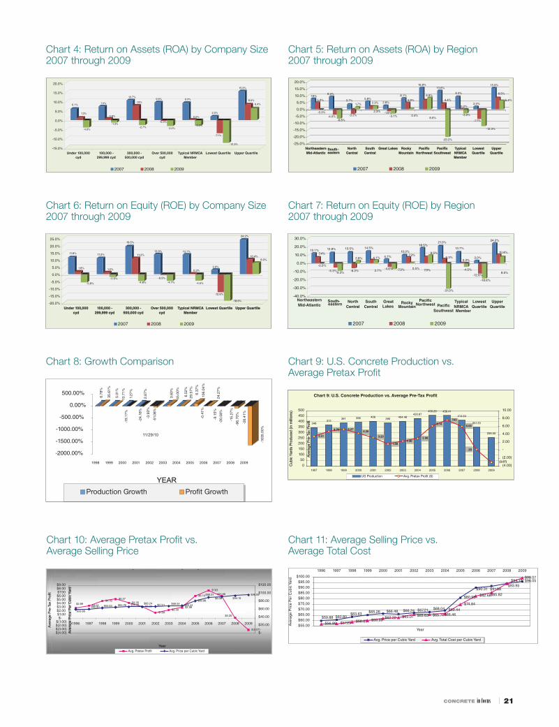
Chart 4: Return on Assets (ROA) by Company Size 2007 through 2009
Chart 6: Return on Equity (ROE) by Company Size2007 through 2009
Chart 5: Return on Assets (ROA) by Region2007 through 2009
Chart 7: Return on Equity (ROE) by Region2007 through 2009
Chart 8: Growth Comparison
6.1%
1.3%
-4.0%
7.4%
0.8%
-1.3%
10.7%
7.9%
-2.7%
9.6%
-0.3%
-3.2%
9.3%
0.2%
-3.0%
2.0%
-7.1%
-12.3%
15.6%
8.5%
6.4%
-15.0%
-10.0%
-5.0%
0.0%
5.0%
10.0%
15.0%
20.0%
Under 100,000cyd
100,000 -299,999 cyd
300,000 -500,000 cyd
Over 500,000cyd
Typical NRMCAMember
Lowest Quartile Upper Quartile
2007 2008 2009
7.9%5.0%
-0.3%
9.3%
-4.0%-6.8%
3.7%
-3.2%
1.7%
5.8%2.3%
2.3%
2.8%
-1.5%-3.1%
8.1%
4.9%
0.4%
15.8%
6.9%
8.5%
13.6%
4.4%
-20.2%
9.3%
0.2%
-3.0%
2.0%
-7.1%
-12.3%
15.6%
8.5%
6.4%
-25.0%
-20.0%
-15.0%
-10.0%
-5.0%
0.0%
5.0%
10.0%
15.0%
20.0%
NortheasternMid-Atlantic
SSouth-eastern
NorthCentral
SouthCentral
Great Lakes RockyMountain
Paci cNorthwest
Paci cSouthwest
TypicalNRMCAMember
LowestQuartile
UpperQuartile
2007 2008 2009
11.8%
1.8%
-5.8%
11.2%
1.2%
-2.0%
19.5%
11.2%
-4.8%
13.9%
-0.5%
-4.7%
13.7%
0.3%
-4.5%
3.0%
-12.6%
-18.6%
24.2%
10.4%8.0%
-20.0%
-15.0%
-10.0%
-5.0%
0.0%
5.0%
10.0%
15.0%
20.0%
25.0%
Under 100,000cyd
100,000 -299,999 cyd
300,000 -500,000 cyd
Over 500,000cyd
Typical NRMCAMember
Lowest Quartile Upper Quartile
2007 2008 2009
12.1%7.4%
-0.5%
12.8%
-5.3%-9.3%
13.5%
-6.2%
2.8%
14.5%
4.1%
3.7%
4.7%
-4.6% -7.3%
10.0%7.3%
0.5%
18.5%
7.9%
9.5%
21.0%
5.3%
-31.0%
13.7%
0.3%
-4.5%
3.0%
-12.6%
-18.6%
24.2%
10.4%
8.0%
-40.0%
-30.0%
-20.0%
-10.0%
0.0%
10.0%
20.0%
30.0%
NortheasternMid-Atlantic
South-eastern
NorthCentral
SouthCentral
Great Lakes
RockyMountain
Paci cNorthwest Paci c
Southwest
TypicalNRMCAMember
LowestQuartile
UpperQuartile
2007 2008 2009
6.78
%
35.6
1%
5.01
%
10.7
1%
1.27
%-1
9.17
%
2.67
%-2
4.18
%
-3.9
3%
-51.
08%
3.60
%
45.0
0%
6.52
%29
.57%
6.37
%
106.
04%
-0.4
1%
24.2
7%-9
.15%
-20.
58%
-15.
27%
-96.
70%
-26.
41%
-163
5.00
%
-2000.00%
-1500.00%
-1000.00%
-500.00%
0.00%
500.00%
1998 1999 2000 2001 2002 2003 2004 2005 2006 2007 2008 2009
YEARProduction Growth
11/29/10
Chart 9: U.S. Concrete Production vs. Average Pretax Profit
348372
391 396 406390 404.48
430.87458.29 456.41
414.64
351.33
258.553.51
4.76 5.274.26
3.23
1.582.30
2.98
6.147.63
6.06
.20
(3.07)0
50
100
150
200
250
300
350
400
450
500
1997 1998 1999 2000 2001 2002 2003 2004 2005 2006 2007 2008 2009
Cub
ic Y
ards
Pro
duce
d (in
mill
ions
)
(4.00)
(2.00)
-
2.00
4.00
6.00
8.00
10.00
Aver
age
Pre
-Tax
Pro
fit
US Production
Chart 10: Average Pretax Profit vs. Average Selling Price
Chart 10: Average Pree-Tax Profit vs. Average Selling Price
$3.51
$4.76$5.27
$4.26$3.23
$1.58$2.30
$2.98
$6.14
$7.63
$(3.07)
$2.89
$6.06
$0.20
$69.44
$80.98
$96.05
$59.88
$60.80 $63.63 $65.26 $66.48 $66.24 $67.21 $68.04
$90.31 $91.88
$94.15
$(4.00)$(3.00)$(2.00)$(1.00)
$-$1.00$2.00$3.00$4.00$5.00$6.00$7.00$8.00$9.00
1996 1997 1998 1999 2000 2001 2002 2003 2004 2005 2006 2007 2008 2009
Year
Aver
age
Pre
-Tax
Pro
fit
$-
$20.00
$40.00
$60.00
$80.00
$100.00
$120.00
Aver
age
Pric
e P
er C
ubic
Yar
d
Avg. Price per Cubic Yard
Chart 11: Average Selling Price vs. Average Total Cost
$69.44
$80.98
$96.05
$56.99 $57.29 $58.87 $59.99$63.01
$74.84
$82.68
$99.07
$59.88 $60.80$63.63 $65.26 $66.48 $66.24 $67.21 $68.04
$90.31 $91.88
$94.15
$62.22$65.63 $65.74$66.46
$85.82
$93.95
$55.00
$60.00
$65.00
$70.00
$75.00
$80.00
$85.00
$90.00
$95.00
$100.00
1996 1997 1998 1999 2000 2001 2002 2003 2004 2005 2006 2007 2008 2009
Year
Ave
rage
Pric
e P
er C
ubic
Yar
d
Avg. Price per Cubic Yard Avg. Total Cost per Cubic Yard

22 ı JANUARY/FEBRUARY 2011
TABLE 2: Efficiency Ratios by Region - 2007 through 2009
TABLE 1: Efficiency Ratios by Company Size - 2007 through 2009
CompanySize
Year Days SalesOutstanding
EBIT toTotalAssets
YardsperHour
YardsperTruck
SalesperEmployee
Var.DeliveryCosts/Minute
<100K
100-299K
300-500K
>500K
Typical
Member
LowestQuartile
Upper
Quartile
200920082007
200920082007
200920082007
200920082007
200920082007200920082007200920082007
66.963.654.1
52.556.553.7
494546
50.748.460.7
51.148.859.946.344.5
8153.643.550.1
-3.30%1.80%7.50%
-.40%2.00%8.40%
-1.20%9.10%
12.30%
-2.90%20.00%10.40%
-2.50%80.00%10.10%
-11.70%-6.10%3.40%6.90%8.90%
16.40%
2.32.32.5
2.52.52.5
2.53.02.9
2.82.73.1
2.72.73.12.33.13.23.03.13.0
2,7353,5563,597
3,4213,9194,334
4,1454,6634,940
4,3535,4655,914
4,0985,1585,5953,9275,1205,5833,9284,8165,818
$181,380$217,600$218,961
$201,029$228,326$243,153
$243,467$279,923$290,909
$238,822$284,730$317,347
$230,900$276,054$304,003$222,693$275,837$273,832$225,633$291,643$315,995
$0.73$0.78$0.69
$0.77$0.81$0.76
$0.78$0.89$0.87
$0.78$0.77$0.78
$0.77$0.79$0.79$0.72$0.95$0.90$0.80$0.95$0.76
Region
Year Days SalesOutstanding
EBIT toTotal Assets
Yardsper Hour
YardsperTruck
Sales perEmployee
Var. DeliveryCosts/Minute
62.7 $232,000 59.4 $271,000 Northeastern
Mid-Atlantic
200920082007
63.2 $255,000
45.2 $225,000 44.8 $266,000 Southeastern
200920082007
41.8 $307,000
52.1 $216,000 45.8 $244,000 North Central
200920082007
121.8 $216,000
46.2 $262,000 55 $318,000 South Central
200920082007
65.3 $295,000
69.2 $202,000 69.3 $230,000 Great Lakes
200920082007 102 $243,000
43.1 $236,000 40.3 $286,000 Rocky
Mountain
200920082007 77.3 $293,000
50.4 $232,000 38.3 $251,000 Pacific
Northwest
200920082007 62 $314,000
44.6 $234,000 32.9 $364,000 Pacific
Southwest
200920082007 50.7 $412,000
51.1 $231,000 48.8 $276,000
TypicalNRMCA
Member
200920082007 59.9 $304,000
46.3 $223,000 44.5 $276,000
LowestQuartile
200920082007
81 $273,000 53.6 $226,000 43.5 $292,000
UpperQuartile
200920082007
50.1
0.10%5.70%8.60%
-6.10%-3.20%10.20%
2.80%-1.50%5.10%
2.80%2.60%6.40%
-2.90%-1.00%3.90%
0.50%5.30%8.30%9.00%7.40%
16.10%-20.00%
4.60%15.00%-2.50%0.80%
10.10%-11.70%
-6.10%3.40%6.90%8.90%
16.40%
2.72.72.3
2.12.12.9
2.82.83.0
2.83.23.5
3.02.92.8
2.63.02.73.53.64.13.03.13.52.72.73.12.33.13.23.03.13.0
3,7474,3744,329
4,1605,2485,601
2,8984,1994,493
5,4086,9857,398
3,8254,5614,644
4,0235,0825,8313,6214,7406,6114,0405,3266,0924,0985,1585,5953,9275,1205,5833,9284,8165,818 $315,995
$0.82$0.83$0.69
$0.58$0.59$0.69
$1.03$0.95$0.92
$0.65$0.73$0.74
$1.01$0.99$0.88
$0.74$0.88$0.75$1.06$1.12$0.86$0.94$0.93$0.93$0.77$0.79$0.79$0.72$0.96$0.90$0.80$0.95$0.76

CONCRETE in focus ı 23
Winter Freezes Water, Not Your Employees’ BrainsBy Eileen Dickson, Vice President of Education, NRMCA
Use the Cold Months to Your A d v a n t a g e : T r a i n a n d Communicate. Winter training
has critical advantages. The simplest is that it changes the training pattern because time is on your side. The adage, “com-municate, communicate, communicate,” really comes into play because frontline supervisors have the time to work and talk with employees side-by-side in a slower pace, solicit suggestions and positively cor-rect mistakes. A clear message is sent that there is an atmosphere where employees are willing and able, to talk with superi-ors, and mutually learn. These personal discussions are a great gage to tell you how the business is doing and how to improve it. Second, for those companies who take advantage of instructor-led or computer-based training, the slow business cycle allows your employee to spend more time to really engage, master the curriculum, and personalize it to the company’s way of doing business. Let’s look at two common scenarios ready mix producers face this time of the year.
Chicago plant manager Jack McKinley felt the cold blow right through him as he
walked the yard. Stan Adamczyk, his senior mixer driver, fi nished shoveling the snow mounted around the steps’ railing up to the batch house. He had also chipped off big patches of ice elsewhere in the yard to decrease a chance of anyone slipping. Stan and the other senior driver kept on all win-ter were getting bored with the little, non-driver tasks. It looked like not one yard of concrete would be poured in the next couple of days. In fact, business had been pretty awful for the last three weeks. Jack wanted to keep them occupied to both his, and their, advantage.
Eight hundred fi fty miles south in Dallas, the weather was a mild 48°F and batchman Raul Perez was having his third can of Dr Pepper with drivers Jose Delgado and Jimmy Dawes. Th ey only had a fi rst round on the books so afterward Jose and Jimmy swept up debris around the conveyor
belts and emptied the trash cans. With the yard work well in hand, Raul needed to fi nd them something to do.
Each of these plant operators started out as mixer drivers so they saw value in the drivers’ delivery skills and yard work. It was an added bonus to their mutual rela-tionship. Yet each plant operator knew that with the experienced drivers, winter was a good time to to brush up on mixer driver skills and knowledge as well as refresh their cross training as substitute batchmen.
In the case of cross-training for batch-ing, adding responsibility increases sub-ordinates’ confi dence in their ability to perform well, not only as a substitute, but when acting in their primary mixer driver role. It also assures that when productiv-ity is of utmost importance in low revenue times, someone competent is on reserve to step in when needed.
education matters
“A clear message is sent that there is an atmosphere where employees are willing, and able, to talk with superiors, and mutually learn. ”

24 ı JANUARY/FEBRUARY 2011357719_Enviro.indd 1 3/10/08 4:12:08 PM
866-958-7267 919-365-8004
www.fortransinc.com
IF YOU ARE PAYING FOR STORAGE OR HAULING PROCESS WATER OFF YOUR SITE,
FORTRANS CAN HELP REDUCE ORELIMINATE THOSE COSTS!
Fortrans process water management can provide solutions to treat process water so that the water can be released to the environment, recycled or returned to themunicipal wastewater treatment system.
Our patented carbon dioxide diffusion injection systems can treat and produce process water that meets EPA standards.
Fortrans systems are designed to be affordable and cost effi cient with minimal maintenance.
All systems are guaranteed to perform to our customers’ satisfaction!
499960_Fortrans.indd 1 11/4/10 8:32:43 AM
As for training specifi c to the mixer driver job function, producers have two new options to consider, both from NRMCA. Recognizing that a producer’s greatest per-formance liability lies within 50%+ of staff who have the same job function, NRMCA updated and adapted its premier mixer driver training curriculum, the Concrete Delivery Professional (CDP) Certifi cation Program©, to an individualized, self-paced online learn-ing tool. Th e online accessibility allows com-panies to train individual drivers without direct interaction with a trainer/supervisor- a perfect fi t when that computer is not batch-ing and a driver is being paid to do nothing between loads! CDP Online™ is also acces-sible anywhere, 24/7, from any computer.
Originally developed with input from ready mix concrete producers of all sizes throughout North America, the material still focuses on instructing drivers in their core competen-cies as well as relaying why specifi c actions are important and what the ramifi cations of
compliance/non-compliance are to themselves, their company and their customers in less than 20-minute units. It measures and documents industry-based standards, a positive reinforce-ment to the driver and company management that there is a measured training record for an employee’s fi le.
Additionally, in Winter 2011 NRMCA will release a new series of Mentor Driver© lessons. As many are aware, there are 80+ video titles in the series. Each will be refor-mulated into individual, interactive lessons, available on a CD. Drivers do NOT need supervision or a peer driver to go through the material. Each lesson comes with two quiz-zes and one fi nal test. When done, the driver prints a certifi cate if he/she passed, showing the company measured and documented the training.
With the pressure of so many wearing multiple hats, NRMCA believes both pro-grams will continue driver training and miti-gate any possible “failure to train” citations
from EEOC or OSHA. NRMCA envisions producers will use the interactive lessons in one of two ways: after training a group of drivers, each driver can be assigned to take the CDP Online™ certifi cation or review in the accompanying individual interactive Mentor Driver© lesson to review what was taught; or if a driver as a “problem” in one performance area, he/she could be assigned to go through that lesson as part of a perfor-mance requirement, again showing the com-pany has been pro-active to address a hole in a driver’s performance.
Results, measurement, return on invest-ment, testing, behavior change, performance improvement, expectations, accountability and learning applied on the job are the indus-try’s future for performance development and enhancement. Let the colds winds of Winter 2011 be your company’s best friend. ■
For more information on NRMCA’s educa-tional off erings, please visit www.nrmca.org.
CONCRETE in focus ı 25
Instant Steam GeneratorDesigned specifically for heating water and
aggregates, all with the one unit.
Fuel savings up to 50%
Low carbon monoxide levels
Full bore steam in 15 seconds
No stationary engineer required
No chemical treatment of water
for More infoCall: 1-800-388-1339
or visit: www.steamengineering.ca
“Will not make aggregate MUSHY”
419624_Steam.indd 1 2/12/09 8:51:46 PM
Ultra-Concrete Washout Filter®
NEW
• Reduce turbidity
• Reduce pH
• Recycle aggregate
• Solve your washout dilemma
UltraTech International Inc.800-764-9548
www.ConcreteFilter.com
before and after
480496_Ultratech.indd 1 5/26/10 11:09:07 AM
Reason #42 - Increase Productivity
Reason #18 - Improve Concrete Properties
Reason #1 - Reinforce Your Bottom Line
The Euclid Chemical Company has been providing field-proven concreteadmixtures for over 100 years. Our century-old dedication to continued researchand development of cutting edge admixture productsputs us on the forefront of concrete technology.
It comes down to one thing, you need a companythat has been there, and will continue to be there.
1-800-321-7628
www.euclidchemical.com
Admixtures
ONE SOURCE. Hundreds of Reasons.
yre productsology.
mpanye there.
100 YEARSof
E X P E R I E N C E
491241_TheEuclid.indd 1 8/18/10 11:47:03 PM

26 ı JANUARY/FEBRUARY 2011
HOWTOcombatreducethe
global warming,
production ofgreenhouse gases,
buildastronger infrastructure.
and
Contact Headwaters Resources for free technical literature and informationon how fly ash use benefits the environment and produces better concrete.
When you specify fly ash as replacement for cement in concrete,you help reduce CO2 emissions from cement production, conservelandfill space, and decrease water usage. You also enhanceworkability and chemical attack resistance, increase strengthand produce more durable concrete.
SPECIFY FLY ASH (a recovered resource)
as a replacement for cementin concrete.
www.flyash.com I 1-888-236-6236MEMBER
373895_Headwaters.indd 1 3/13/08 4:32:44 PM465116_Infocus.indd 1 2/12/10 8:34:23 AM
ADMIXTURESBASF Construction Chemicals. . . . . . . . . . . . Inside Front Coverwww.masterbuilders.com
The Euclid Chemical Company . . . . . . . . . 25www.euclidchemical.com
Solomon Colors . . . . . . . . . . . . . . . . . . . . . 15www.solomoncolors.com
CEMENTHolcim. . . . . . . . . . . . . . . . . . . . . . . . . . . . . 3www.holcim.us
CONCRETE CHIPPINGCoast 2 Coast . . . . . . . . . . . . . . . . . . . . . . 26www.C2C-chipping.com
CONCRETE COLORANTSDavis Colors . . . . . . . . . . . . . . . . . . . . . . . 18www.daviscolors.com
CONCRETE CURING EQUIPMENTKemco Systems, Inc. . . . . . . . . . . . . . . . . . 10www.kemcosystems.com
CONCRETE WASH-OUTUltraTech International, Inc. . . . . . . . . . . . . 25www.spillcontainment.com
ENVIRONMENTALEnviro-Port, Inc. . . . . . . . . . . . . . . . . . . . . 24www.enviro-port.com
Fortrans, Inc.. . . . . . . . . . . . . . . . . . . . . . . 24www.fortransinc.com
FLY ASHHeadwaters Resources . . . . . . . . . . . . . . . 26www.fl yash.com
MERGERS & ACQUISITIONS/INVESTMENT BANKINGFMI Corporation. . . . . . . . . Inside Back Coverwww.fminet.com
MIXER TRUCKSContinental Mixers . . . . . . . . . . . . . . . . . . . 4www.continentalmixers.com
STEEL FIBERSBekaert Corp . . . . . . . . . . . . . . . . . . . . . . . . 6www.bekaert.com
SUSPENSIONS - TRUCK LIFT AXLEHendrickson Auxilliary Axle Systems . . . . . . 5www.hendrickson-intl.com
TESTING EQUIPMENT & MATERIALSHumboldt Mfg. Company . . . . . . . . . . . . . . 10www.humboldtmfg.com
WATER HEATING EQUIPMENTHeatec, Inc. . . . . . . . . . . . Outside Back Coverwww.heatec.com
Kemco Systems, Inc. . . . . . . . . . . . . . . . . . 10www.kemcosystems.com
Steam Engineering . . . . . . . . . . . . . . . . . . 25www.steamengineering.ca
advertisers’ index/advertiser.com

*Company noted has been represented by FMI
MERGERS & ACQUISITIONS | FINANCIAL ADVISORY SERVICES
FMI is pleased to have served as advisor on the following transactions:
For more information, visit our Web site at www.fminet.com, or contact:George Reddin at 919.785.9286 / [email protected]
Will Hill at 303.398.7237 / [email protected]
The assets of
andMirimec Trucking Inc.
have been acquired by
•Superior Asphalt & Concrete •Western States Asphalt•Transtate Asphalt•Mid Columbia Asphalt•Blue Mountain Asphalt•Basin Asphalt
have been acquired byhas been acquired by
The assets, barging,quarry and constructionaggregates operations ofJim Smith Contracting
has been acquired by has been acquired by
has been acquired by
has sold itsGunnison County Colorado
operations to
OldcastleMaterials, Inc.
The stock of
Gibraltar NationalCorporation(a subsidiary of
Triss Corporation)
has been acquired by
andTom Brook, Inc.
were acquired by
Elmer Larson, LLC
has been acquired by
Florida Rock Industries, Inc.(a U.S. subsidiary of CRH,Dublin, Ireland)
has been acquired by
Selected assets of
Heavy Civil Division
have been acquired by
J.C. Compton Company(dba Riverbend Sand & Gravel
Valley Concrete & Graveland Salem Road & Driveway)
has been acquired by
OldcastleMaterials, Inc.
(a U.S. subsidiary of CRH,Dublin, Ireland)
(a Rinker GroupLimited company)
Nally & Haydon, LLCand its affiliates
sold itsEastern Kentucky
operations to asubsidiary of
has been acquired by
Flatiron and Turner jointventured for the acquisition
FMI is the premier investment banking and management
consulting firm serving the worldwide engineering and
construction industry. For more than 55 years, FMI has
built a reputation for assisting our clients in the creation
and realization of value in their firms.
500883_FMI.indd 1 10/18/10 11:11:32 AM

FIRESTORM HEATER
FIRED TANK
HOT OIL HEATER
FUEL TANK
CHILLER
HOT OIL PIPE COILS
FOR
CONCRETEPRODUCERS
PRODUCTS
WE offer a number
of products for concrete producers.
Our heating products enable you to extend your working season into cold-weather months by making concrete mixes that are much warmer than ambient temperatures. This is achieved by heating mix water. Or by heating stock piles. Or both.
Our Firestorm heater is our most popular water heating product. It is a direct-contact water heater with extremely high thermal effi ciency: up to 99 percent.
Our fi red tank is an economical alternative to the Firestorm heater. It combines a burner and fi re tube with a fully insulated storage tank.
Our hot oil heater can be
used to heat mix water stored in tanks
that have hot oil pipe coils. Or it can preheat stockpiles of
sand or aggregate. Or it can do both.
Our chillers, which are made by Carrier, cool mix water during hot summer periods.
We also make fuel tanks that meet UL-142 standards. And we make hot oil pipe coils that can be embedded under stockpiles or installed in tanks.
Please contact us to discuss products most suitable for your heating and cooling needs.
HEATEC,INC. an Astec Industries Company
5200 WILSON RD • CHATTANOOGA, TN 37410 USA 800.235.5200 • FAX 423.821.7673 • heatec.com
®HEATEC
502753_Heatec.indd 1 10/25/10 11:51:51 AM

CONCRETE in focus ı 29
P arts I and II of the Concrete Quality series1,2 discussed that to attain good concrete quality a concrete producer
needs to target a low standard deviation of compressive strength. In order to reduce the strength standard deviation the material, manufacturing and testing variations need to be lowered. This article discusses con-crete strength variability due to variation in water and air contents.
Water Content Variation and its Effect on Strength Variation
Compared to other ingredients, there are several sources (and potential errors) by which mixing water is incorporated in a concrete mixture. Th ese sources and ways to ensure that the batch water is within tolerance of the designed amount will be discussed in a later article. ASTM C943 and ACI 1174 state that the total mixing water should be within ±3% of the quan-tity required by the mix design. ASTM C94 also requires that the added water should be within ±1% of the design total mixing water. Th ese standards do not establish accuracy requirements for individual sources of water, such as for water added from the water tank on the concrete truck. Th e NRMCA Plant Certifi cation inspection process has accu-racy requirements for water measurement in the plant and for water tanks that are based on target quantities. For the purpose of this discussion, it is assumed that for plants and construction practices operating under a good standard of control the mixing water content can vary within ±5% of the required quantity 95% of the time. In other words for a concrete mixture with a design mixing water content of 250 lb/yd3, the actual water content can vary by ±12.5 lb/yd3.
compared to higher w/cm – see Appendix A for more discussions). Th is means that a ±5% variation in cement content will result in a ±5% compressive strength variation (based on the discussions in Appendix A this is valid only for w/cm around 0.50). If the mixing water content varies by ±5% of the target value 95% of the time, the eff ect is that the resulting compressive strength variation should be within ±5% of the aver-age strength 95% of the time.
Air Content Variation and its Effect on Strength Variation
ASTM C94 and ACI 117 state that for air entrained concrete the tolerance is ±1.5%. Table 2 has only two data sets with air entrained concrete. Both the data sets show that there is a higher compliance with air content tolerances compared to slump tolerances. Based on that data one could conservatively assume that for plants and construction practices operating under a good standard of control the air contents of air entrained concrete can vary within ±1.5% of the average 95% of the time. Table 2 has 3 data sets with non air entrained concrete. ASTM C94 and ACI 117 do not state tol-erances for non air entrained concrete. Th e air content variations in non air entrained concrete are expected to be lower than in air entrained concrete. Assuming a tolerance of ±0.75%, the 3 data sets show that for plants and construction practices operating under a good standard of control the air contents of non air entrained concrete can vary within ±0.75% of the average 95% of the time.
A common rule of thumb is every 1% increase in air content will reduce the con-crete compressive strength by 5%. So the air content variation of ±1.5% will result in a
During a fi eld evaluation conducted by NRMCA the mixing water content cal-culated from the batch records and other reported sources of water was found to range from 227 to 256 lb/yd3 with an average of 243 lb/yd3. Th is was determined from 12 loads of the same mixture. From this evalua-tion, 94% of the values were within the range of ±12.5 lbs. One could also consider the ASTM C94 and ACI 117 allowable slump tolerance of ±1.5 in. (for concrete of slump greater than 4 in.), with all else being equal, as roughly resulting from a ±5% variation in water content. As part of a diff erent study the author received project test data from several concrete producers. Each project test data consisted of slump, air content, tem-perature, 7 and 28 day strengths measured on the same concrete sample over a period of several months. Some of that data are sum-marized in Tables 1-3. Table 1 shows that barring Producer C the remaining four data sets met the slump requirement within tol-erance exceeding 95% and averaged 96.3%. So, the assumption that plants and construc-tion practices operating under a good stan-dard of control have a mixing water content variation of ±5% of the required quantity 95% of the time seems reasonable.
For a concrete mixture at a given w/cm, a ±5% variation in mixing water will have the same eff ect on the w/cm as a ±5% variation in the cement content. A commonly used rule of thumb is that one pound of cement equates to a compressive strength between 8 to 12 psi. (Th is is a simplistic assumption that is valid only for w/cm around 0.50 to 0.60 or for concrete with 28-day compres-sive strength ranging from 4000 to 5000 psi; for lower w/cm concrete, a pound of cement contributes lesser to compressive strength as
tech talk
Variation in Concrete Strength Due to Water and Air Content VariationPart IV of Concrete Quality SeriesBy Karthik Obla, Ph.D., P.E., VP, Technical Services, NRMCA

30 ı JANUARY/FEBRUARY 2011
DiscussionTh e above analysis can be used to illustrate why non air entrained
concrete has a lower variability in compressive strength. It was shown that non air entrained concrete typically has an air content varia-tion of ±0.75% which can result in a ±3.75% variation in compres-sive strength. When this is added to the water content variation as in the above example it results in s = 267 psi for the average measured compressive strength of 5000 psi. However there are instances where in the combinations of some admixtures and cementitious materials even non air entrained concrete mixtures may attain high air content variations thus leading to potentially higher strength variations. For example, Table 2 shows that for producers C and D1 the air contents of their non air entrained concrete mixtures exceeded ±0.75% of the average about 10% of the time.
Table 3 is a statistical summary of project test results sent by the fi ve diff erent concrete producers. Th e mean and standard deviation (SD) of slump, air content, temperature and 28-day strengths and SD of densities and 7-day strengths are provided. Th e following observa-tions can be made:1. Th e SD of 7-day strength is higher and correlates well with the SD
of the 28-day strength.2. Th e SD of the 28-day strength varies from 438 psi to 1258 psi and
corresponds to an ACI 214 standard of concrete control from Very Good to Poor.
3. Th e SD of slump and air contents correlates with the SD of the 28-day strength. Th e predicted 28-day strength SD is calculated from the percent in compliance with slump and air content toler-ances as discussed in the previous section. Th e slump variation is converted to a water content variation. Th e predicted 28-day strength SDs suggests that producers A and D1 have the low-est variabilities followed by producer B and fi nally producer C. Producer D2 does have a low predicted SD but reported a high measured 28-day strength SD. Producer D2 had combined the test data from several diff erent laboratories and the resulting test-
ing variations have made it harder to interpret that set of data. Producer C has the lowest percent in compliance with C94 slump tolerance limits which resulted in the highest SD of concrete slump. Producer C also had the highest SD of concrete tempera-ture. Th is suggests that producer C might have a high variation in water content which can explain the high measured SD of 28-day strength. Producer A on the other hand attained the highest per-cent in compliance with slump and air content and ended with the lowest measured SD of 28-day compressive strength.To summarize, in order to attain a low SD of 28-day strength it is
important for the producer to attain a low variation in water content and air content as they contribute signifi cantly to the variation in strength. A start can be made by the producer by maintaining a very tight control on slump and air content.
±7.5% compressive strength variation. In the case of air entrained concrete since the air content is within ±1.5% of the specifi ed value 95% of the time the resulting compressive strength variation should be within ±7.5% of the average strength 95% of the time.
Combined Effect of Water and Air Content Variation on Strength Variation
It is assumed the mixing water and air content and the resulting compressive strength are normally distributed.
So far we know the following:95% of the time the water content is between 0.95W and 1.05W
where W is the target mixing water content. Assuming a normal probability distribution this would result in 97.5% of the time the water content is less than 1.05W and as a result
97.5% of the time the strength is greater than 0.95X where X is the average compressive strength.
In the same way it can be concluded that 97.5% of the time the air content is less than (A+1.5) where A is the specifi ed air content and as a result
97.5% of the time the strength is greater than 0.925X (1-0.075).
Combining the water and air content probabilities we can state that:
95% (0.975x0.975) of the time the water content is lesser than 1.05W and the air content is lesser than (A+1.5) and as a result
95% of the time the strength is greater than 0.875X (1-0.05-0.075).
Th is is somewhat of a conservative approach since the above approach assumes that high slump and high air content are mutually exclusive events where as in reality a high water content is likely to lead to a high air content and vice-versa.
Let us assume the compressive strength test results are normally distributed with a standard deviation (s). So, for the 95% probability it follows that:
X – 1.64s = 0.875X. Simplifying we gets = 0.0762XIf the average measured compressive strength (X) is 5000 psi then
s = 381 psi. ACI 214R-025 states that s<400 psi would denote excel-lent standard of concrete control for general construction testing. However it is important to realize that the value of s calculated here (albeit conservatively) is solely due to variation in the water and air contents. Variation due to cement, SCMs, aggregates, admixtures, mixing, transporting, delivery time, temperature, curing and testing is likely to signifi cantly increase this value.
“To attain a low SD of 28-day strength, it is important for the producer to attain a low variation in water content and air content, as they contribute significantly
to the variation in strength.”
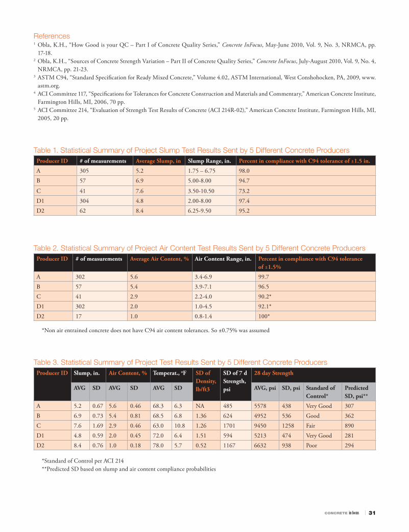
CONCRETE in focus ı 31
References1 Obla, K.H., “How Good is your QC – Part I of Concrete Quality Series,” Concrete InFocus, May-June 2010, Vol. 9, No. 3, NRMCA, pp.
17-18.2 Obla, K.H., “Sources of Concrete Strength Variation – Part II of Concrete Quality Series,” Concrete InFocus, July-August 2010, Vol. 9, No. 4,
NRMCA, pp. 21-23.3 ASTM C94, “Standard Specifi cation for Ready Mixed Concrete,” Volume 4.02, ASTM International, West Conshohocken, PA, 2009, www.
astm.org.4 ACI Committee 117, “Specifi cations for Tolerances for Concrete Construction and Materials and Commentary,” American Concrete Institute,
Farmington Hills, MI, 2006, 70 pp.5 ACI Committee 214, “Evaluation of Strength Test Results of Concrete (ACI 214R-02),” American Concrete Institute, Farmington Hills, MI,
2005, 20 pp.
Table 1. Statistical Summary of Project Slump Test Results Sent by 5 Different Concrete ProducersProducer ID # of measurements Average Slump, in. Slump Range, in. Percent in compliance with C94 tolerance of ±1.5 in.
A 305 5.2 1.75 – 6.75 98.0
B 57 6.9 5.00-8.00 94.7
C 41 7.6 3.50-10.50 73.2
D1 304 4.8 2.00-8.00 97.4
D2 62 8.4 6.25-9.50 95.2
Table 2. Statistical Summary of Project Air Content Test Results Sent by 5 Different Concrete ProducersProducer ID # of measurements Average Air Content, % Air Content Range, in. Percent in compliance with C94 tolerance
of ±1.5%
A 302 5.6 3.4-6.9 99.7
B 57 5.4 3.9-7.1 96.5
C 41 2.9 2.2-4.0 90.2*
D1 302 2.0 1.0-4.5 92.1*
D2 17 1.0 0.8-1.4 100*
*Non air entrained concrete does not have C94 air content tolerances. So ±0.75% was assumed
Table 3. Statistical Summary of Project Test Results Sent by 5 Different Concrete ProducersProducer ID Slump, in. Air Content, % Temperat., oF SD of
Density, lb/ft3
SD of 7 d Strength, psi
28 day Strength
AVG SD AVG SD AVG SD AVG, psi SD, psi Standard of Control*
Predicted SD, psi**
A 5.2 0.67 5.6 0.46 68.3 6.3 NA 485 5578 438 Very Good 307
B 6.9 0.73 5.4 0.81 68.5 6.8 1.36 624 4952 536 Good 362
C 7.6 1.69 2.9 0.46 63.0 10.8 1.26 1701 9450 1258 Fair 890
D1 4.8 0.59 2.0 0.45 72.0 6.4 1.51 594 5213 474 Very Good 281
D2 8.4 0.76 1.0 0.18 78.0 5.7 0.52 1167 6632 938 Poor 294
*Standard of Control per ACI 214**Predicted SD based on slump and air content compliance probabilities

32 ı JANUARY/FEBRUARY 2011
CODES AND SUSTAINABILITYErin Ashley, Ph.D., LEED AP(240) [email protected]
COMMUNICATIONSFrank Cavaliere(240) [email protected]
CONCRETE PROMOTIONGlenn Ochsenreiter(240) [email protected] Huffman(503) [email protected] Hansen(515) [email protected] Kresge(610) [email protected] O’Neill, LEED AP(585) [email protected] Pool(281) [email protected] Miller, P.E.(904) [email protected]
ENGINEERINGColin Lobo Ph.D., P.E.(240) [email protected] Lemay, P.E., S.E., LEED AP(847) [email protected] Obla, Ph.D., P.E.(240) [email protected]
REGULATORY AFFAIRSGary Mullings(240) [email protected]
FINANCIAL ACTIVITIESMichael Olivarri, CPA(240) [email protected] Muzzatti(240) [email protected] Waugh(240) [email protected]
GOVERNMENT AFFAIRSKerri Leininger(240) [email protected] Walgenbach(240) [email protected]
INDUSTRY RELATIONSNicole Maher(240) [email protected]
INFORMATION TECHNOLOGYLawrence Afable(240) [email protected] Zhu(240) [email protected]
MARKETINGGlenn Ochsenreiter(240) [email protected] McBurney(240) [email protected]
MEETINGSNicole Maher(240) [email protected] Moore(240) [email protected]
MEMBERSHIPKathleen Carr-Smith(240) [email protected] Pittmon(240) [email protected]
OFFICE OF THE PRESIDENTRobert Garbini, P.E., President(240) [email protected] Angelastro(240) [email protected]
OPERATIONS/EQUIPMENT MAINTENANCEGary Mullings(240) [email protected]
PUBLICATIONSJacques Jenkins(240) [email protected]
RMC RESEARCH & EDUCATION FOUNDATIONJulia Garbini(240) [email protected] LeFevre(240) [email protected]
SAFETYDavid Ayers, CHMM, CSP, MS(240) [email protected] Mullings(240) [email protected]
TRAINING/EDUCATION/CERTIFICATIONEileen Dickson(240) [email protected] Dickens(240) [email protected]
Who to Call at NRMCA LOCAL: (301) 587-1400
TOLL-FREE: 1 (888) 846-7622 WEB SITE: www.nrmca.org
Appendix A – Calculation of Strength Variation From Water Content Variation
Th e ACI 211 table of strength versus w/cm for non air-entrained concrete and the best-fi t straight line has been plotted below.
Th e slope is -9600 psi. Th e following table shows the calculated change in strength (based on the straight line equation) for a one pound change in cement content for concrete with a water content of 300 lb/yd3 and for diff erent target w/cm values. Th e numbers would be slightly higher for lower water content.
w/cm Change in Strength, psi/lb of cement
0.4 5
0.5 8
0.6 12
0.7 16
It is seen that the strength change for a change in one pound of cement is 8-12 psi for concrete in the 4000 to 5000 psi range and for w/cm of 0.50 to 0.60.
Using the straight line equation, the percentage change in strength for a ±5% change in cement content for concretes for a given water content is calculated and is shown below:
w/cm Change in Strength, %
0.4 3.3%
0.5 4.9%
0.6 7.4%
0.7 11.4%
Th us it is clear that a 5% change in cement content will result in a 5% change in compressive strength only around w/cm of 0.50.
A similar situation occurs when the variation in strength is cal-culated for variation of water-content with the cement held constant at the target cement content. If the water content varies 5% from the target value, the strength variation will depend on the w/c and also slightly on the target value of the water content. From the table below it becomes clear that a 5% change in water content will result in a 5% change in compressive strength only around w/cm of 0.50.
Variation in Strength at Diff erent Water Contents
w/cm 280 lbs 300 lbs 310 lbs
0.4 3.1% 3.3% 3.4%
0.5 4.6% 4.9% 5.1%
0.6 6.9% 7.4% 7.6%
0.7 10.6% 11.4% 11.8%
Higher w/cm concrete mixtures appear to be more vulnerable to cement and water content variations as compared to lower w/cm concrete mixtures. A given percent change in cement or water contents does not lead to the same percent change in compressive strength because strength is related inversely to water-cementitious ratio and not directly to cement or water content as commonly assumed. ■

CONCRETE in focus ı 33
W hat is the water demand of the sand that your company is using to produce concrete? Is it 33 gal/
cy or 42 gal/cy? Can there possibly be a difference of this magnitude? What fac-tors contribute to the water demand of the concrete? How do you determine the water demand of the sand? How can it be used to save money?
Water demand is primarily impacted by the characteristics of the sand. Th e primary characteristics of sand that impact water demand are its particle shape, surface tex-ture and grading. In general, crushed manu-factured sand requires a higher mixing water content than natural river sands that have a more rounded shape and smoother surface texture.
Ground granulated blast furnace slag (slag) and fl y ash enhance the slump of a con-crete mix. A mix design containing 564 lbs/cy of portland cement has less slump than a mix that contains 50% Class F fl y ash. Fly ash, because of its rounded particle shape, reduces the water demand of a concrete mixture for a target slump. Air-entrainers and most water reducers also contribute to a higher slump.
A standard concrete mixture must be evaluated when estimating the water demand. One might choose a portland cement content of 564 lbs/cy, coarse aggregate, water, and the production sand. Th e concrete mixture is tested in laboratory conditions to estimate the quantity of water required to produce a 4-inch slump. Th e following describes proce-dures used by the authors.
A Type II (MH) cement conforming to ASTM C150 is used.
Th e coarse aggregate is manufactured stone from southern Pennsylvania, conform-ing to ASTM C33 Size #57.
Th e sand used was washed, natural sand produced in northeast Maryland and
turn for fi ve revolutions. Approximately 10 pounds of water was weighed, and small amounts were introduced and allowed to mix with the other constituent materials. We added these small increments until it appeared that a 4-inch slump was attained upon visual assessment. Slump tesing was performed in accordance with ASTM C143. Once a 4-inch slump was obtained, the mix-ing was terminated. Th e unit weight and air content was measured and recorded. A set of fi ve compressive strength cylinders was also fabricated. All testing was performed in accordance with ASTM standards.
From this trial batch evaluation proce-dure, the amount of mixing water required to obtain the 4-inch slump was equivalent
conforms to the requirements of ASTM C33 and approved for use by the Maryland State Highway Administration.
Size ∑ Wt Ret %Pass
3/8” 0 100
No. 4 2.0 98.0
No. 8 15.6 84.4
No. 16 26.5 73.5
No. 30 42.7 57.3
No. 50 77.7 22.3
No. 100 96.3 3.7
PAN 100.0 0.0
Total 2.61
Listed below are the mixture proportions used;
Material SP GRAV SSD Wts per cubic yard(lbs) Absolute Volume(cf )
Cement 3.15 564 2.87
SSD Stone 2.87 1800 10.05
SSD Sand 2.59 1454 9.00
Mixing Water 1.00 264 4.23
Air,% 3.00 0.81
A non-air entrained concrete batch of a volume of 0.8 cubic foot was mixed in the quality control laboratory at the author’s pro-duction plant. Th e moisture content of the coarse and fi ne aggregate was determined.
From experience and past performance, 1800 lbs/cy of coarse aggregate was used. For optimum pumping placement, it is esti-mated that 10.0 - 10.3 cubic feet of stone in a cubic yard of concrete appears to provide the best performance.
All of the constituents were weighed according to design mixture proportions. Th e stone, sand and small amount of water were placed in a 2.0 cubic foot mixer. Th e mixer was allowed to turn for fi ve revolu-tions. Th e cement was then added to the mixer. Again, the mixer was allowed to
quality corner
Water Demand – What is it? And what’s it used for? PART IBy Fernando Rodriguez, Rowen Concrete, Inc. and Jack Hoy, Swope & Associates (SIKA Admixtures)
to 300 lbs/cy or 36 gallons per cubic yard. It should be noted at this point that the concrete sands available in this one small regional marketplace have a range of as low as 33 gallons per cubic yard up to as high as 44 gallons per cubic yard. With this in mind, it is easily demonstrated how important it is to be well informed as to the demands of your concrete sands.
Now that the water demand has been determined, it can be used for development of concrete mixtures and mix optimization. Th e information can be used to establish the cementitious materials required for diff er-ent water cement ratios, admixture dosage rates and yield targets. Knowing the water demand of the local materials can help opti-mize cementitious material contents and
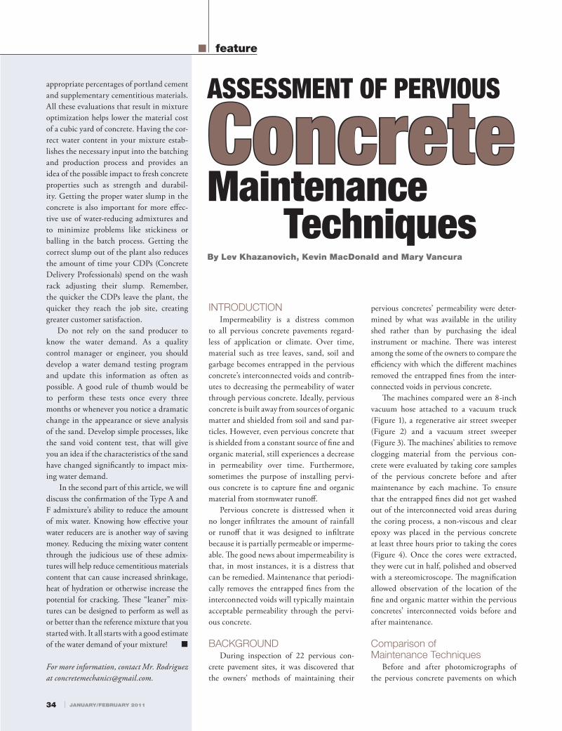
appropriate percentages of portland cement and supplementary cementitious materials. All these evaluations that result in mixture optimization helps lower the material cost of a cubic yard of concrete. Having the cor-rect water content in your mixture estab-lishes the necessary input into the batching and production process and provides an idea of the possible impact to fresh concrete properties such as strength and durabil-ity. Getting the proper water slump in the concrete is also important for more eff ec-tive use of water-reducing admixtures and to minimize problems like stickiness or balling in the batch process. Getting the correct slump out of the plant also reduces the amount of time your CDPs (Concrete Delivery Professionals) spend on the wash rack adjusting their slump. Remember, the quicker the CDPs leave the plant, the quicker they reach the job site, creating greater customer satisfaction.
Do not rely on the sand producer to know the water demand. As a quality control manager or engineer, you should develop a water demand testing program and update this information as often as possible. A good rule of thumb would be to perform these tests once every three months or whenever you notice a dramatic change in the appearance or sieve analysis of the sand. Develop simple processes, like the sand void content test, that will give you an idea if the characteristics of the sand have changed signifi cantly to impact mix-ing water demand.
In the second part of this article, we will discuss the confi rmation of the Type A and F admixture’s ability to reduce the amount of mix water. Knowing how eff ective your water reducers are is another way of saving money. Reducing the mixing water content through the judicious use of these admix-tures will help reduce cementitious materials content that can cause increased shrinkage, heat of hydration or otherwise increase the potential for cracking. Th ese “leaner” mix-tures can be designed to perform as well as or better than the reference mixture that you started with. It all starts with a good estimate of the water demand of your mixture! ■
For more information, contact Mr. Rodriguez at [email protected].
INTRODUCTIONImpermeability is a distress common
to all pervious concrete pavements regard-less of application or climate. Over time, material such as tree leaves, sand, soil and garbage becomes entrapped in the pervious concrete’s interconnected voids and contrib-utes to decreasing the permeability of water through pervious concrete. Ideally, pervious concrete is built away from sources of organic matter and shielded from soil and sand par-ticles. However, even pervious concrete that is shielded from a constant source of fi ne and organic material, still experiences a decrease in permeability over time. Furthermore, sometimes the purpose of installing pervi-ous concrete is to capture fi ne and organic material from stormwater runoff .
Pervious concrete is distressed when it no longer infi ltrates the amount of rainfall or runoff that it was designed to infi ltrate because it is partially permeable or imperme-able. Th e good news about impermeability is that, in most instances, it is a distress that can be remedied. Maintenance that periodi-cally removes the entrapped fi nes from the interconnected voids will typically maintain acceptable permeability through the pervi-ous concrete.
BACKGROUNDDuring inspection of 22 pervious con-
crete pavement sites, it was discovered that the owners’ methods of maintaining their
pervious concretes’ permeability were deter-mined by what was available in the utility shed rather than by purchasing the ideal instrument or machine. Th ere was interest among the some of the owners to compare the effi ciency with which the diff erent machines removed the entrapped fi nes from the inter-connected voids in pervious concrete.
Th e machines compared were an 8-inch vacuum hose attached to a vacuum truck (Figure 1), a regenerative air street sweeper (Figure 2) and a vacuum street sweeper (Figure 3). Th e machines’ abilities to remove clogging material from the pervious con-crete were evaluated by taking core samples of the pervious concrete before and after maintenance by each machine. To ensure that the entrapped fi nes did not get washed out of the interconnected void areas during the coring process, a non-viscous and clear epoxy was placed in the pervious concrete at least three hours prior to taking the cores (Figure 4). Once the cores were extracted, they were cut in half, polished and observed with a stereomicroscope. Th e magnifi cation allowed observation of the location of the fi ne and organic matter within the pervious concretes’ interconnected voids before and after maintenance.
Comparison of Maintenance Techniques
Before and after photomicrographs of the pervious concrete pavements on which
ASSESSMENT OF PERVIOUS
ConcreteConcrete Maintenance TechniquesBy Lev Khazanovich, Kevin MacDonald and Mary Vancura
feature
34 ı JANUARY/FEBRUARY 2011
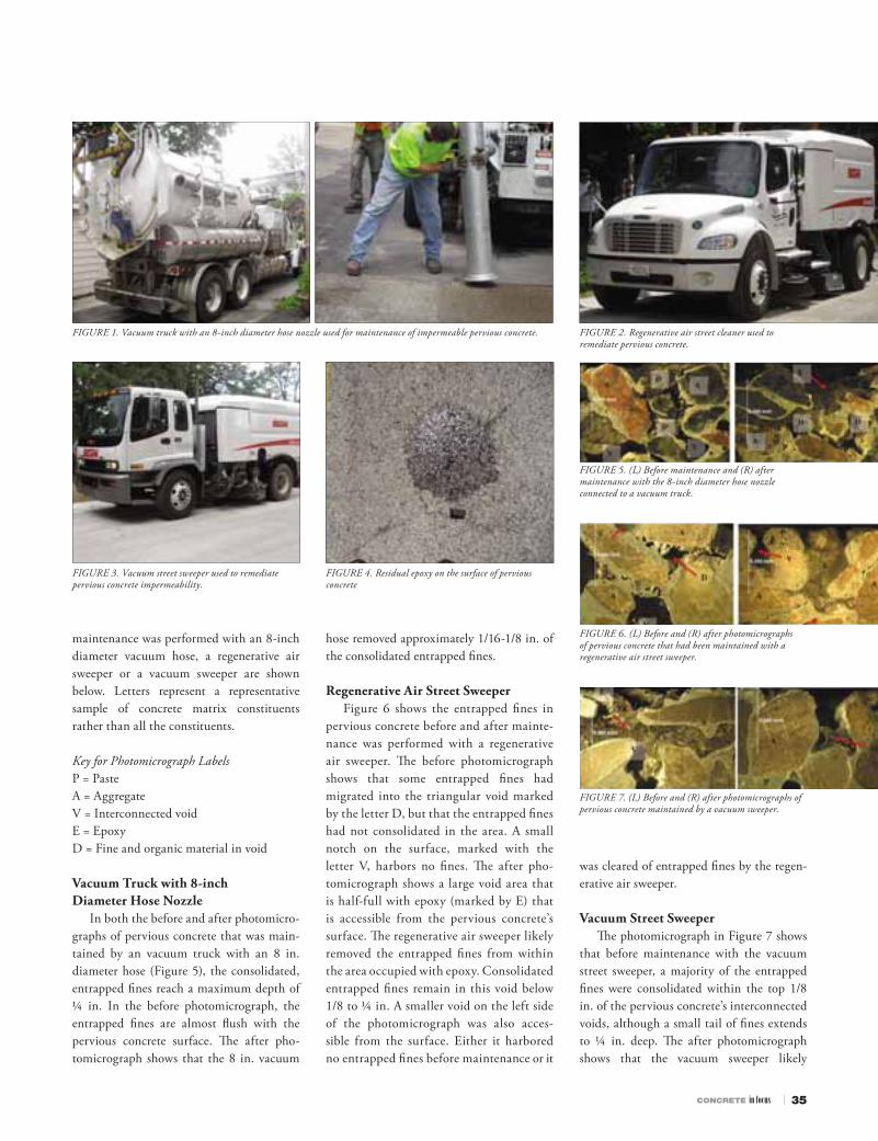
CONCRETE in focus ı 35
FIGURE 1. Vacuum truck with an 8-inch diameter hose nozzle used for maintenance of impermeable pervious concrete.
FIGURE 3. Vacuum street sweeper used to remediate pervious concrete impermeability.
FIGURE 2. Regenerative air street cleaner used to remediate pervious concrete.
FIGURE 4. Residual epoxy on the surface of pervious concrete
FIGURE 5. (L) Before maintenance and (R) after maintenance with the 8-inch diameter hose nozzle connected to a vacuum truck.
FIGURE 6. (L) Before and (R) after photomicrographs of pervious concrete that had been maintained with a regenerative air street sweeper.
FIGURE 7. (L) Before and (R) after photomicrographs of pervious concrete maintained by a vacuum sweeper.
maintenance was performed with an 8-inch diameter vacuum hose, a regenerative air sweeper or a vacuum sweeper are shown below. Letters represent a representative sample of concrete matrix constituents rather than all the constituents.
Key for Photomicrograph LabelsP = PasteA = AggregateV = Interconnected voidE = EpoxyD = Fine and organic material in void
Vacuum Truck with 8-inch Diameter Hose Nozzle
In both the before and after photomicro-graphs of pervious concrete that was main-tained by an vacuum truck with an 8 in. diameter hose (Figure 5), the consolidated, entrapped fi nes reach a maximum depth of ¼ in. In the before photomicrograph, the entrapped fi nes are almost fl ush with the pervious concrete surface. Th e after pho-tomicrograph shows that the 8 in. vacuum
hose removed approximately 1/16-1/8 in. of the consolidated entrapped fi nes.
Regenerative Air Street SweeperFigure 6 shows the entrapped fi nes in
pervious concrete before and after mainte-nance was performed with a regenerative air sweeper. Th e before photomicrograph shows that some entrapped fi nes had migrated into the triangular void marked by the letter D, but that the entrapped fi nes had not consolidated in the area. A small notch on the surface, marked with the letter V, harbors no fi nes. Th e after pho-tomicrograph shows a large void area that is half-full with epoxy (marked by E) that is accessible from the pervious concrete’s surface. Th e regenerative air sweeper likely removed the entrapped fi nes from within the area occupied with epoxy. Consolidated entrapped fi nes remain in this void below 1/8 to ¼ in. A smaller void on the left side of the photomicrograph was also acces-sible from the surface. Either it harbored no entrapped fi nes before maintenance or it
was cleared of entrapped fi nes by the regen-erative air sweeper.
Vacuum Street SweeperTh e photomicrograph in Figure 7 shows
that before maintenance with the vacuum street sweeper, a majority of the entrapped fi nes were consolidated within the top 1/8 in. of the pervious concrete’s interconnected voids, although a small tail of fi nes extends to ¼ in. deep. Th e after photomicrograph shows that the vacuum sweeper likely

36 ı JANUARY/FEBRUARY 2011
removed the entrapped fi nes from the top 1/8 in. of a ¼ inch-deep void.
Other Photomicrographs from After Maintenance
Th e photomicrographs in Figure 8 were additional photos taken of pervious concrete following maintenance by the 8 in. vacuum hose, regenerative air sweeper, or vacuum sweeper. Th e photos reinforce that the entrapped fi nes were mostly concentrated in the top ¼ in. of the pervious concrete and, regardless of the maintenance performed, only the top 1/16-1/8 in. of entrapped fi nes were removed.
FIGURE 8. Photomicrographs of pervious concrete following maintenance by 8 in. vacuum hose, regenerative air sweeper, or vacuum sweeper.
Coarse Sand FinesWhile small fi nes and organic mat-
ter remained within the top ¼ in. of the interconnected void spaces and tended to consolidate into tightly packed masses, the larger fi nes such as coarse sand particles were observed in interconnected voids throughout the depth of the cores. Figure 9 shows an example of coarse sand particles
with fi ne and organic matter depended on the exposure of the pervious concrete to fi ne and organic material, which varied by site.
ACKNOWLEDGEMENTSTh is research was completed with a grant
from the Ready Mixed Concrete (RMC) Research & Education Foundation.
Mark Maloney, Tom Wesolowski and Mike Shaughnessy, City of Shoreview Public Works Department.
Andjela Tomovic, City of Saint Cloud Department ofEngineering.
For more information contact:
Mary VancuraGraduate Research AssistantUniversity of MinnesotaDepartment of Civil Engineering500 Pillsbury Drive S.E.Minneapolis, MN 55455Phone: 612-597-3431E-mail: [email protected]
Kevin MacDonaldVice President of Engineering ServicesCemstone Products Co.2025 Centre Pointe Blvd #300Mendota Heights, MN 55120Phone: 612-363-7111E-mail: [email protected]
Lev KhazanovichAssociate ProfessorUniversity of MinnesotaDepartment of Civil Engineering500 Pillsbury Drive S.E.Minneapolis, MN 55455Phone: 612-624-4764E-mail: [email protected] ■
that migrated 3 in. into a pervious concrete pavement.
FIGURE 9. Pervious concrete exposed to sand during the winter and spring snow melt. Sand particles migrated three inches into the pervious concrete voids.
CONCLUSIONTh ree possible methods of pervious con-
crete pavement maintenance were attempted, and all were equally eff ective at removing the top 1/8” of fi ne and organic material from the pervious concrete pavements. Th e fi ne and organic materials that were responsible for the partial or total impermeability of the per-vious concretes typically consolidated within ¼ in. of the concrete’s surface. Pervious con-crete voids deeper than ¼ in. were rarely fi lled by these materials. If fi nes were found in the interconnected void areas beneath ¼ in., these fi nes were typically larger sand particles and did not appear to impede permeability of the pervious concrete.
Entrapped fi nes were not entirely removed during maintenance. Instead, the total thick-ness of consolidated fi nes within a void space was decreased and the remaining fi nes were disturbed enough so that the pervious con-crete was able to infi ltrate water according to design. Th e rate at which the voids were fi lled
Th e research taking place at the University of Minnesota was funded by the RMC Research & Education Foundation. Th e Foundation supports research and educational programs that will increase professionalism and quality in the concrete industry. Additional information about the Foundation’s work may be found at www.rmc-foundation.org.
Additional pervious concrete resources available from the RMC Research & Education Foundation include:■ Pervious Concrete Research Compilation■ Construction & Maintenance Assessment of Pervious Concrete■ Hydraulic Performance Assessment of Pervious Concrete Pavements for
Stormwater Management Credit■ Portland Cement Pervious Pavement: Field Performance Investigation
on Parking Lot and Roadway PavementsAll of the reports noted above are included on the Foundation’s
Research Supporting Sustainable Development deliverables CD.
Other pervious concrete research projects currently under-way include:■ Heat Island Mitigation Th rough Use of Pervious Concrete■ Pervious Concrete Mix Design for Wearing Course Applications


![[kfut lpuk lEcU/kh if=dk [k.M 32] vad 2 vDVcj 2014 & ekpZ 2015ibm.nic.in/writereaddata/files/08112015170100BMI octob… · · 2015-08-11Kuber Associates & Others, Appellants v](https://img.pdfslide.us/doc/110x75/5aae6ec97f8b9a5d0a8c1ca4/kfut-lpuk-lecukh-ifdk-km-32-vad-2-vdvcj-2014-ekpz-octob2015-08-11kuber.jpg)

![[gdb/TTTTTTTTTTTTTTTTTTTTTTTTT È s¬£ Ý²Í [LHJOLY...0\oo:\sx^klvo aaa \kc]yplvs]] myw 0y\:o\]yxkv?]o 9xvc *u ublft b #*( +-up ifmq tibqf +(0"' &"' , [gdb/ttttttttttttttttttttttttt](https://img.pdfslide.us/doc/110x75/6015c57f84cfbf33e91879ce/gdbttttttttttttttttttttttttt-s-0oosxklvo-aaa-kcyplvs.jpg)