Embed Size (px)
Citation preview
8/7/2019 22 Recent developments in centrifuge technology
http://slidepdf.com/reader/full/22-recent-developments-in-centrifuge-technology 1/5
Please cite this article in press as: H. Anlauf, Recent developments in centrifuge technology, Sep. Purif. Technol. (2007),
doi:10.1016/j.seppur.2007.05.012
ARTICLE IN PRESS+Model
SEPPUR-8901; No.of Pages5
Separation and Purification Technology xxx (2007) xxx–xxx
Recent developments in centrifuge technology
Harald Anlauf ∗
Universit¨ at Karlsruhe (TH), Institut f¨ ur MVM, D-76128 Karlsruhe, Germany
Abstract
Centrifugation represents one of the main groups of mechanical particle-liquid separation processes. There are available various centrifuges
for sedimentation and filtration, which are operating continuously or discontinuously. The tasks for centrifugal separation are very wide spread
from liquid clarification and purification, particle thickening, solids demoistening, particle fractionating and sorting, solids washing, liquid–liquid
separation to extraction of solids or liquids. Applications of centrifuges can be found in all kinds of industry, in environmental protection, water
treatment, etc. In the centrifugal field mass forces are present during the separation process. This leads to specific advantages and disadvantages in
comparison to competing separation processes. Research and development for centrifugal processes today has not coming to an end but several newideas to use centrifugal forces for separation and new technical developments in this field can be observed. After description of some fundamentals
and presentation of an overview of the technical variations some aspects of advantages and disadvantages of centrifuges in comparison to other
separation techniques arediscussed and examples forrecent researchand technical development as well as actual trends in the field of centrifugation
are given.
© 2007 Published by Elsevier B.V.
Keywords: Solid–liquid separation; Centrifugation; Filtration; Sedimentation
1. Introduction
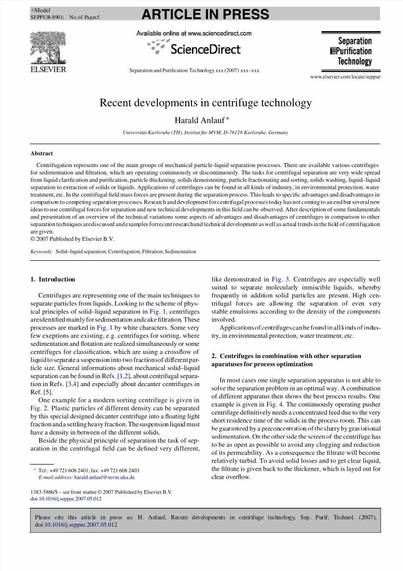
Centrifuges are representing one of the main techniques to
separate particles from liquids. Looking to the scheme of phys-
ical principles of solid–liquid separation in Fig. 1, centrifuges
areidentified mainly for sedimentation andcake filtration. These
processes are marked in Fig. 1 by white characters. Some very
few exeptions are existing, e.g. centrifuges for sorting, where
sedimentation and flotation are realized simultaneously or some
centrifuges for classification, which are using a crossflow of
liquid to separate a suspension into two fractionsof different par-
ticle size. General informations about mechanical solid–liquid
separation can be found in Refs. [1,2], about centrifugal separa-
tion in Refs. [3,4] and especially about decanter centrifuges in
Ref. [5].
One example for a modern sorting centrifuge is given inFig. 2. Plastic particles of different density can be separated
by this special designed decanter centrifuge into a floating light
fraction and a settling heavy fraction. The suspension liquid must
have a density in between of the different solids.
Beside the physical principle of separation the task of sep-
aration in the centrifugal field can be defined very different,
∗ Tel.: +49 721 608 2401; fax: +49 721 608 2403.
E-mail address: [email protected].
like demonstrated in Fig. 3. Centrifuges are especially well
suited to separate molecularly inmiscible liquids, whereby
frequently in addition solid particles are present. High cen-
trifugal forces are allowing the separation of even very
stable emulsions according to the density of the components
involved.
Applications of centrifuges can be found in all kinds of indus-
try, in environmental protection, water treatment, etc.
2. Centrifuges in combination with other separation
aparatuses for process optimization
In most cases one single separation apparatus is not able to
solve the separation problem in an optimal way. A combination
of different apparatus then shows the best process results. One
example is given in Fig. 4. The continuously operating pusher
centrifuge definitively needs a concentrated feed due to the very
short residence time of the solids in the process room. This can
be guaranteed by a preconcentration of the slurry by graviational
sedimentation. On the other side the screen of the centrifuge has
to be as open as possible to avoid any clogging and reduction
of its permeability. As a consequence the filtrate will become
relatively turbid. To avoid solid losses and to get clear liquid,
the filtrate is given back to the thickener, which is layed out for
clear overflow.
1383-5866/$ – see front matter © 2007 Published by Elsevier B.V.
doi:10.1016/j.seppur.2007.05.012
8/7/2019 22 Recent developments in centrifuge technology
http://slidepdf.com/reader/full/22-recent-developments-in-centrifuge-technology 2/5
Please cite this article in press as: H. Anlauf, Recent developments in centrifuge technology, Sep. Purif. Technol. (2007),
doi:10.1016/j.seppur.2007.05.012
ARTICLE IN PRESS+Model
SEPPUR-8901; No.of Pages5
2 H. Anlauf / Separation and Purification Technology xxx (2007) xxx–xxx
Nomenclature
ac centrifugal acceleration
A area
cv volume concentration
C centrifugal factor
F c centrifugal forceg gravity
h height
hcap capillary height
ms, mL solid, liquid mass
pc centrifugal pressure differen
pg, pL gas, liquid pressure
r , R radius
V L liquid volume
x3,50 mean particle size
Greek letters
δ wetting angle
γ L,g surface tension
ρL liquid density
ω angular velocity
To avoid flooding of pusher centrifuges, to increase through-
put and to be able to process even smaller particles, recently
developed pusher centrifuges have not only an integrated pre-
concentration zone (see Fig. 5) but in addition a pulsed feed
[6].
The feed stream is pulsed, which means, that during back
stroke of the pusher plate the slurry valve is open and during thedangerous forward stroke the feed valve is closed.
Fig. 1. Centrifuges in the scheme of solid–liquid separation techniques.
Fig. 2. Decanter centrifuge for sorting (type Flottweg).
Fig. 3. Tasks for centrifugal separation.
Fig. 4. Combination of pusher centrifuge and settling basin.
3. Centrifugal forces and consequences for the
separation process
The use of mass forces in the centrifugal field for the sepa-
ration process leads to specific advantages and disadvantages in
comparison to competing separation processes using the same
or other physical separation principles and other forces like
gas differential pressure (vacuum pump, compressor), hydraulic
pressure (slurry pump) or mechanical pressure (diaphragm, pis-
ton). In many cases not only the application of a centrifuge is
possible, but there are competing techniques and a detailled dis-
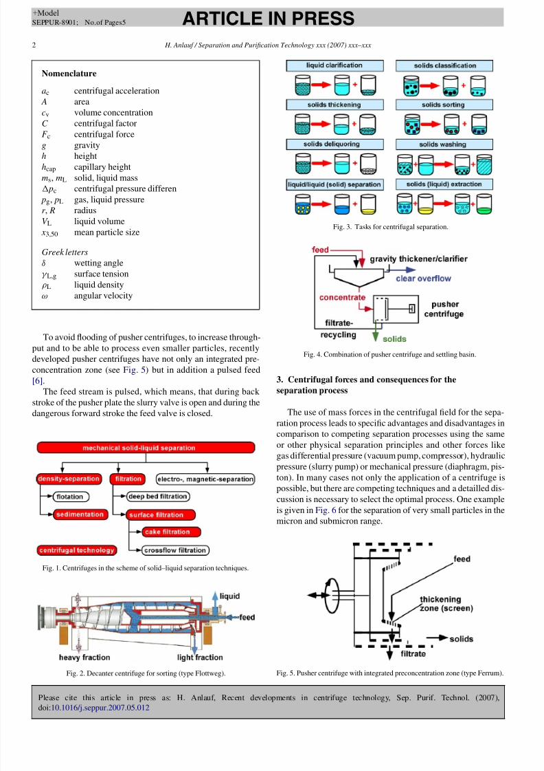
cussion is necessary to select the optimal process. One example
is given in Fig. 6 f or the separation of very small particles in the
micron and submicron range.
Fig. 5. Pusher centrifuge with integrated preconcentration zone (type Ferrum).
8/7/2019 22 Recent developments in centrifuge technology
http://slidepdf.com/reader/full/22-recent-developments-in-centrifuge-technology 3/5
Please cite this article in press as: H. Anlauf, Recent developments in centrifuge technology, Sep. Purif. Technol. (2007),
doi:10.1016/j.seppur.2007.05.012
ARTICLE IN PRESS+Model
SEPPUR-8901; No.of Pages5
H. Anlauf / Separation and Purification Technology xxx (2007) xxx–xxx 3
Fig. 6. Competition of disc stack separator, precoat drum filter and crossflow module.
The principle situation for centrifugal separation is shown in
Fig. 7 and the calculation of the centrifugal force for sedimen-
tation and filtration is given in Eqs. (1) and (2).
Sedimentation:
F c = msac = msrω2= msCg (1)
Filtration:
pc =
F c
A =
mLCg
A =
V LρLCg
A = ρLCgh (2)
An undesired but not avoidable consequence of acting mass
forces in sediments of centrifuges is the remaining concentra-
tion profile like to be seen in Fig. 8. The sediment layers at
the bottom are highly compressed whereby the surface layer of
the sediment remaines very loose packed. Concentration profile
means moisture profile and different rheological behaviour of
the sediment. The slippery upper regions of such sediment may
cause problems during the transport by the screw in decanter
centrifuges.
Fig. 7. Principle situation for particle separation in centrifuges.
Fig. 8. Concentration profile in a sediment of a centrifuge in the equilibrium
state.
To avoid solids transport problems decanter centrifuges with
special designed sludge discharge systems have been developed
(see Fig. 9) [7].
The sluge is compressed maximally at the largest radius of
the double cone bowl and then transported by hydraulic pressure
through the gap of a weir plate to the sludge outlet.
For centrifugal filtration processes one can distinguish
between the phase of filter cake formation and the desaturation
of filter cakes. Both of them show specific effects directly con-nected with the centrifugal forces. Parallel to filtration the mass
forcesare actingdirectly on theparticles andtherefore additional
sedimentation is present in every case. The same phenomeneon
is valid for vacuum or pressure filtration processes but in the
case of filter centrifuges the sedimentation velocity is increased
by the centrifugal factor and predominates in many cases the
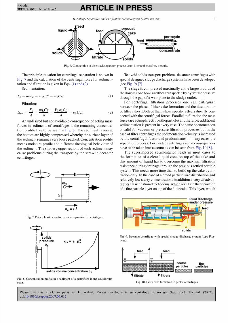
separation process. For peeler centrifuges some consequences
have to be taken into account as can be seen from Fig. 10 [8].
The superimposed sedimentation leads in most cases to
the formation of a clear liquid zone on top of the cake and
this amount of liquid has to overcome the maximal filtration
resistance during drainage through the previous settled particle
system. This needs more time than to build up the cake by fil-tration only. In the case of a broad particle size distribution and
relatively low slurry concentrations in addition a very disadvan-
tagues classification effect occurs, whichresults in the formation
of a fine particle layer on top of the filter cake. This layer, which
Fig. 9. Decanter centrifuge with special sludge discharge system (type Flot-
tweg).
Fig. 10. Filter cake formation in peeler centrifuges.
8/7/2019 22 Recent developments in centrifuge technology
http://slidepdf.com/reader/full/22-recent-developments-in-centrifuge-technology 4/5
Please cite this article in press as: H. Anlauf, Recent developments in centrifuge technology, Sep. Purif. Technol. (2007),
doi:10.1016/j.seppur.2007.05.012
ARTICLE IN PRESS+Model
SEPPUR-8901; No.of Pages5
4 H. Anlauf / Separation and Purification Technology xxx (2007) xxx–xxx
Fig. 11. Ultrasonic level control for peeler centrifuges (type KMP).
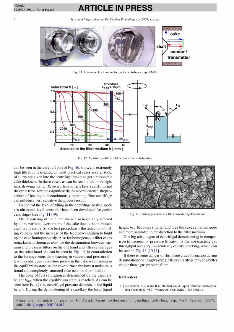
Fig. 12. Moisture profile in a filter cake after centrifugation.
can be seen in the very left part of Fig. 10, shows an extremely
high filtration resistance. In most practical cases several shots
of slurry are given into the centrifuge basket to get a reasonable
cake thickness. In these cases, as can be seen in the more right
hand drawing in Fig. 10, several fine particle layers can form and
the cycle time increasessignificantly. As a consequence, thepro-
cedure of feeding a discontinuously operating filter centrifuge
can influence very sensitive the process result.
To control the level of filling in the centrifuge basket, mod-
ern ultrasonic level controller have been developed for peeler
centrifuges (see Fig. 11) [9].
The dewatering of the filter cake is also negatively affected
by a fine particle layer on top of the cake due to the increased
capillary pressure. So the best procedure is the reduction of fill-
ing velocity and the increase of the feed concentration to buildup the cake homogeneously. Also for homogeneous filter cakes
remarkable differences exist for the desaturation between vac-
uum and pressure filters on the one hand and filter centrifuges
on the other hand. As can be seen in Fig. 12, in contradiction
to the homogeneous demoistening in vacuum and pressure fil-
ters in centrifuges a moisture profile in the cake is remaining in
the equilibrium state. At the cake surface the lowest moisture is
found and completely saturated cake near the filter medium.
The zone of full saturation is determined by the capillary
height hcap, when the equilibrium state is reached. As can be
seen from Eq. (2) the centrifugal pressure depends on the liquid
height. During the demoistening of a capillary the local liquid
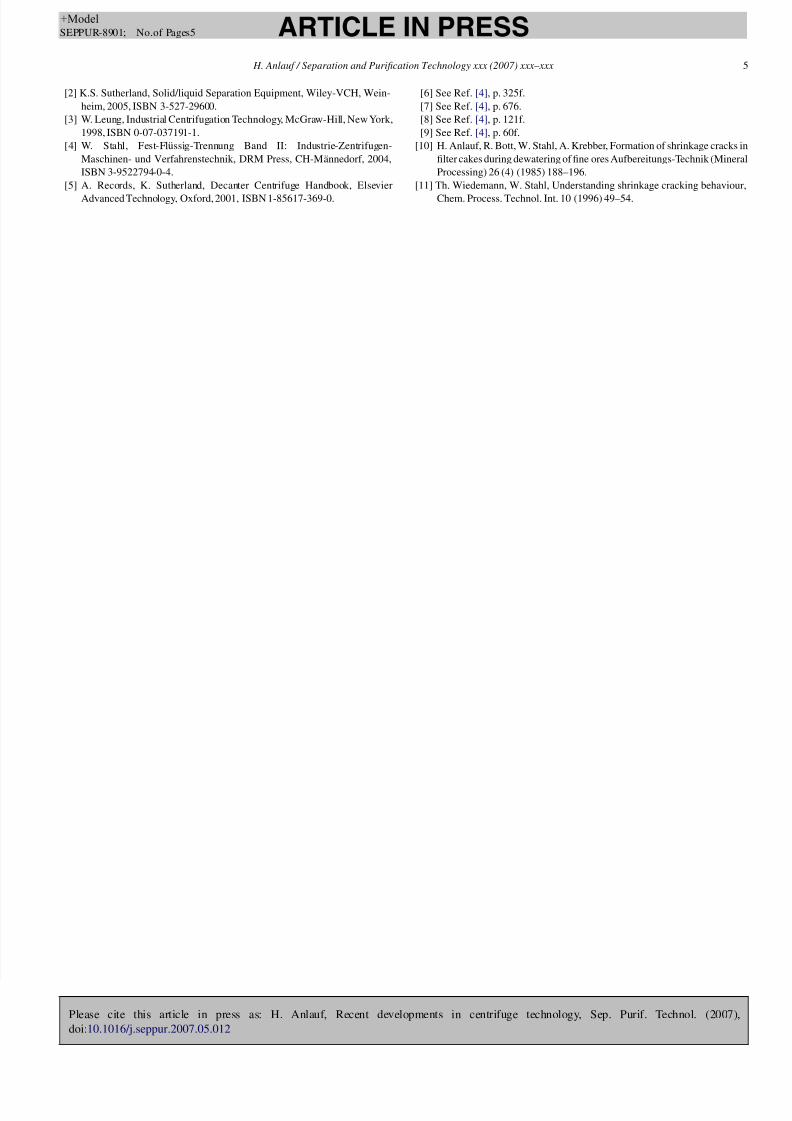
Fig. 13. Shrinkage cracks in a filter cake during desaturation.
height hloc becomes smaller and thus the cake remaines more
and more saturated in the direction to the filter medium.One big advantague of centrifugal demoistening in compar-
ison to vacuum or pressure filtration is the not existing gas
throughput and very low tendency of cake cracking, which can
be seen in Fig. 13 [10,11].
If there is some danger of shrinkage crack formation during
desaturationor duringwashing, a filter centrifuge maybe a better
choice than a gas pressure filter.
References
[1] A. Rushton, A.S. Ward, R.G. Holdich, Solid–liquid Filtration and Separa-
tion Technology, VCH, Weinheim, 1996, ISBN 3-527-28613-6.
8/7/2019 22 Recent developments in centrifuge technology
http://slidepdf.com/reader/full/22-recent-developments-in-centrifuge-technology 5/5
Please cite this article in press as: H. Anlauf, Recent developments in centrifuge technology, Sep. Purif. Technol. (2007),
doi:10.1016/j.seppur.2007.05.012
ARTICLE IN PRESS+Model
SEPPUR-8901; No.of Pages5
H. Anlauf / Separation and Purification Technology xxx (2007) xxx–xxx 5
[2] K.S. Sutherland, Solid/liquid Separation Equipment, Wiley-VCH, Wein-
heim, 2005, ISBN 3-527-29600.
[3] W. Leung, Industrial Centrifugation Technology, McGraw-Hill, New York,
1998, ISBN 0-07-037191-1.
[4] W. Stahl, Fest-Flussig-Trennung Band II: Industrie-Zentrifugen-
Maschinen- und Verfahrenstechnik, DRM Press, CH-Mannedorf, 2004,
ISBN 3-9522794-0-4.
[5] A. Records, K. Sutherland, Decanter Centrifuge Handbook, Elsevier
Advanced Technology, Oxford, 2001, ISBN 1-85617-369-0.
[6] See Ref. [4], p. 325f.
[7] See Ref. [4], p. 676.
[8] See Ref. [4], p. 121f.
[9] See Ref. [4], p. 60f.
[10] H. Anlauf, R. Bott, W. Stahl, A. Krebber, Formation of shrinkage cracks in
filter cakes during dewatering of fine ores Aufbereitungs-Technik (Mineral
Processing) 26 (4) (1985) 188–196.
[11] Th. Wiedemann, W. Stahl, Understanding shrinkage cracking behaviour,
Chem. Process. Technol. Int. 10 (1996) 49–54.