Embed Size (px)
Citation preview
2145392 Gas Turbine
Somsak Chaiyapinunt
Alongkorn Pimpin
Gas turbines, like other heat engines, achieve conversion of heat energy of a fuel into
mechanical energy by carrying out a sequence of processes, i.e. a cycle, on its working fluid.
Typically a parcel of this fluid is first compressed and then heated either by burning a fuel in
the fluid or by bringing the fluid into contact with an external source of heat energy. The hot
high pressure flow then expands back to atmospheric pressure and in doing so provides both
sufficient work to drive the original compression process and residual work to drive an
external load.
Unlike the petrol or diesel engine however in a gas turbine these processes do not take
place within the same compartment but in separate compartments or components, i.e., a
compressor, a combustion chamber, (or heat exchanger) and a turbine. A consequence of this
type of arrangement is that, under a steady rotational speed of the component, i.e., pressure,
temperature, velocity, are steady. Additionally as a parcel of fluid passes from one
component to another component it continually displaces a parcel of fluid in front of it and it
is itself replaced behind by the next parcel. The gas turbine is therefore characterized by
steady flow processes as opposed to the essentially non-flow processes of reciprocating
machinery.
Motivation
Gas turbines are becoming increasingly used as power plants for a wide variety of
applications around the world. Originally they were developed solely for aircraft propulsion
where their inherent low specific weight (i.e. mass/unit power) made them essential for high
speed flight. For this particular purpose they have been developed to a high degree of
efficiency both thermodynamically and mechanically.
Due partly to the impetus from the aircraft engine field and also to other significant
operational advantages, industrial gas turbines have been and are being developed for such
diverse applications as electrical power peak lopping stations, fire fighting pump sets, natural
gas pumping and compressor units, factory power and process heating plants, heavy lorry
propulsion, rail and ship propulsion.
Objective
To study the performance of a gas turbine unit.
Problem statements
The specific problem statements are as follows.
The first experiment is for the specified gas generator turbine speed (or specified gas
flow rate). Find the output power from the power turbine and the efficiency of the power
2
turbine and the gas turbine unit for the adjustable range of the power turbine operating
speeds.
The second experiment is to adjust the speed of gas generator turbine. For the
adjustable range of the gas generator turbine operating speeds, find the compressor delivery
pressure, air mass flow rate, fuel flow, power output and specific fuel consumption at a
specified power turbine speed (or specified gas generator turbine and power turbine speed
ratio).
Approach
General
Under the specified experimental conditions, measures the fuel flow, measures the air
flow, measures the temperature, measures the pressure, measures the speed and measures the
power output.
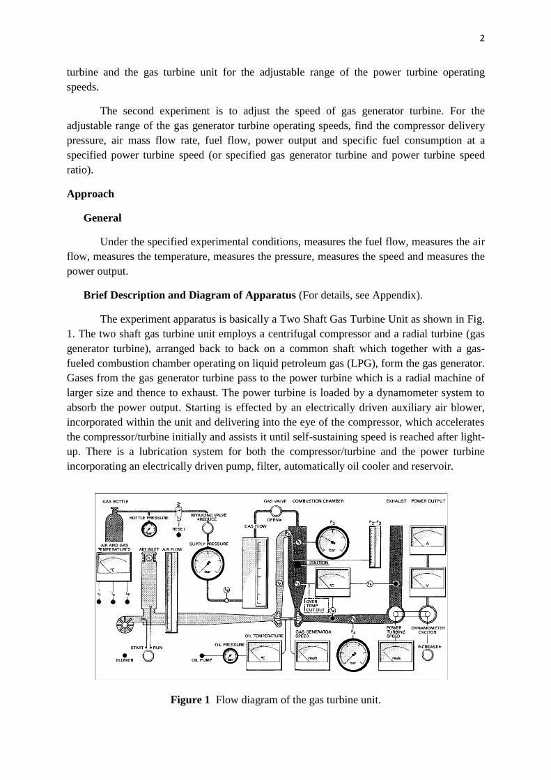
Brief Description and Diagram of Apparatus (For details, see Appendix).
The experiment apparatus is basically a Two Shaft Gas Turbine Unit as shown in Fig.
1. The two shaft gas turbine unit employs a centrifugal compressor and a radial turbine (gas
generator turbine), arranged back to back on a common shaft which together with a gas-
fueled combustion chamber operating on liquid petroleum gas (LPG), form the gas generator.
Gases from the gas generator turbine pass to the power turbine which is a radial machine of
larger size and thence to exhaust. The power turbine is loaded by a dynamometer system to
absorb the power output. Starting is effected by an electrically driven auxiliary air blower,
incorporated within the unit and delivering into the eye of the compressor, which accelerates
the compressor/turbine initially and assists it until self-sustaining speed is reached after light-
up. There is a lubrication system for both the compressor/turbine and the power turbine
incorporating an electrically driven pump, filter, automatically oil cooler and reservoir.
Figure 1 Flow diagram of the gas turbine unit.
3
Operating Instructions
General
The Cussons Gas Turbine Unit is designed to permit analysis of the performance
characteristics of the gas generator, power turbine and combustion chamber using the
instrumentation displayed on the front panel. Operation over a wide range of speed and load
is possible which, together with the facility for varying the speed ratio between the gas
generator and the power turbine, means that a test programmed on the Two Shaft Gas
Turbine system can be carried out. By carefully controlling the speed ratio of the gas
generator and power turbine to a constant value, a coupled power turbine can be simulated,
whereas if the power turbine speed is held constant, then the gas generator simulates a single
spool turbo jet.
Starting
1. Connect the cooling water supply and drain.
2. Connect the gas bottle.
3. Connect the electrical supply and start the exhaust fan blower.
4. Set the air inlet control to the start position.
5. Close the gas valve and open the valve on the gas bottle.
6. Set the dynamometer excitation to maximum.
7. Start the oil pump.
8. Press the reset button.
9. Start the blower.
10. Set the gas pressure to 2.0 bar with the reducing valve.
11. Press the ignition button and hold it in whilst opening the gas valve to give a gas flow
of 0.5 g/s.
12. If ignition, as shown by an increase in T3, does not occur within 5 seconds of gas flow
commencing, close the gas valve to allow unburned gas to clear the system before
continuing from item 11.
13. Release the ignition button.
14. Open the gas valve slowly to give a gas generator speed of 1000 rev/s taking care to
keep combustion chamber temperature below 900C (this operation may take some
minutes depending on the oil temperature).
15. Turn the air inlet control to the run position.
4
16. Switch off the blower.
Operating Limitations
1. During the test program the following limits must not be exceeded:
Gas generator speed 2000 rev/s
Power turbine speed 600 rev/s
Gas generator turbine inlet temperature 900C
2. Set the gas pressure to 1.5 bar before making fuel flow readings.
3. The gas turbine unit has certain safety features built into it. If the combustion
chamber temperature T3 is allowed to exceed 900C due to over fuelling, or if the oil
pressure falls below 1.5 bar, then the gas supply will be shut of by means of a
solenoid valve. To re-start the turbine after operation of the solenoid valve, follow
starting instructions 4-17.
Stopping
1. Close the valve on the bottle.
2. Close the gas valve.
3. Once the turbines have stopped reset the air inlet control to the start position.
4. Re-start the blower.
5. When T4 has dropped below 80C and the oil temperature drops below 40C:
i) Switch off the blower.
ii) Switch off the oil pump.
iii) Turn off the gas supply.
iv) Turn off the water supply.
v) Turn off and disconnect the electrical supply.
Notes on Operating Instructions
Starting
When ignition initially occurs, a slight ‘pop’ is heard, and a sharp rise of combustion
chamber temperature (T3) takes place. If the gas valve is then opened too quickly, T3 will rise
above 950C and the over temperature protection will operate. Should this occur, close the
gas valve, press the ‘reset’ button and restart the turbine according to the starting procedures
described earlier. Whilst accelerating T3 should be kept below 850C by ‘slowly’ opening the
gas valve as the turbine speed increases. When the gas generator speed reaches 1000 rps,
leave the gas valve in this position and turn the air inlet control switch to the run position and
switch off the blower.
5
Operation
When varying the load on the power turbine, sudden large movements of the
dynamometer exciter control should be avoided, so that high transient belt loads (which may
cause the belt to jump the pulleys and cause damage) can be avoided. It is convenient when
taking a set of readings to first set the fuel flow at the desired level by adjustment of the fuel
control valve, and then (if required) trimming the reducing valve to give a fuel supply
pressure of 1.5 bar.
Stopping
When the turbine has been stopped and the system is being cooled by operating the
blower, it is essential to leave the blower running until the temperature of T4 has dropped to
less than 80C and the oil temperature to less than 40C.
Experimental Procedures
Exp 1. Run and maintain the gas generator turbine at a speed about 1200 rps and vary the
speed of the power turbine from 100 to 550 rps (i.e. 100, 200, 250, 300, 350, 400,
450, 500, 550 rps).
Exp 2. Run and maintain the power turbine at a speed about 550 rps and vary the speed of
the gas generator turbine from 1000 to 1400 rps (i.e. 1000,1050, 1100, 1150, 1200,
1300, 1400 rps).
Experimental Results
Exp 1: 1.1 Plot output power vs power turbine speed for a specified gas generator turbine
speed.
1.2 Plot efficiency of the power turbine vs power turbine speed for a specified gas
generator turbine speed.
1.3 Plot efficiency of the gas turbine unit vs power turbine speed for a specified gas
generator speed.
(Note: in this case, the efficiency of the gas turbine unit is defined as the ratio of
the output power from the power turbine to the power input from the external
source (fuel) to the gas turbine unit.)
Exp 2: 2.1 Plot compressor delivery pressure vs gas generator turbine speed.
2.2 Plot fuel flow vs gas generator turbine speed.
2.3 Plot power output vs gas generator turbine speed.
6
2.4 Plot specific fuel consumption vs gas generator turbine speed.
Discuss all graphs in details. (i.e. how each parameter varied with other parameters?, what
does each graph tell you?)
Note: Part of the information described in this lab sheet comes from detail specifications
from the Cussons technology P9005 Two Shaft Gas Turbine Unit
References and Recommended Readings
1. Frost, T.H., A First Course in Gas Turbine Technology, published by G Cussons Limited,
England.
2. Johnson W. R., The handbook of Fluid Dynamics, CRC Press, 1998.
3. Turns, S.R. Thermal Fluid Sciences An Integrated Approach, Cambridge University
Press, 2006.

7
Example of lab data sheet
8
Appendix
1. Fundamental concepts
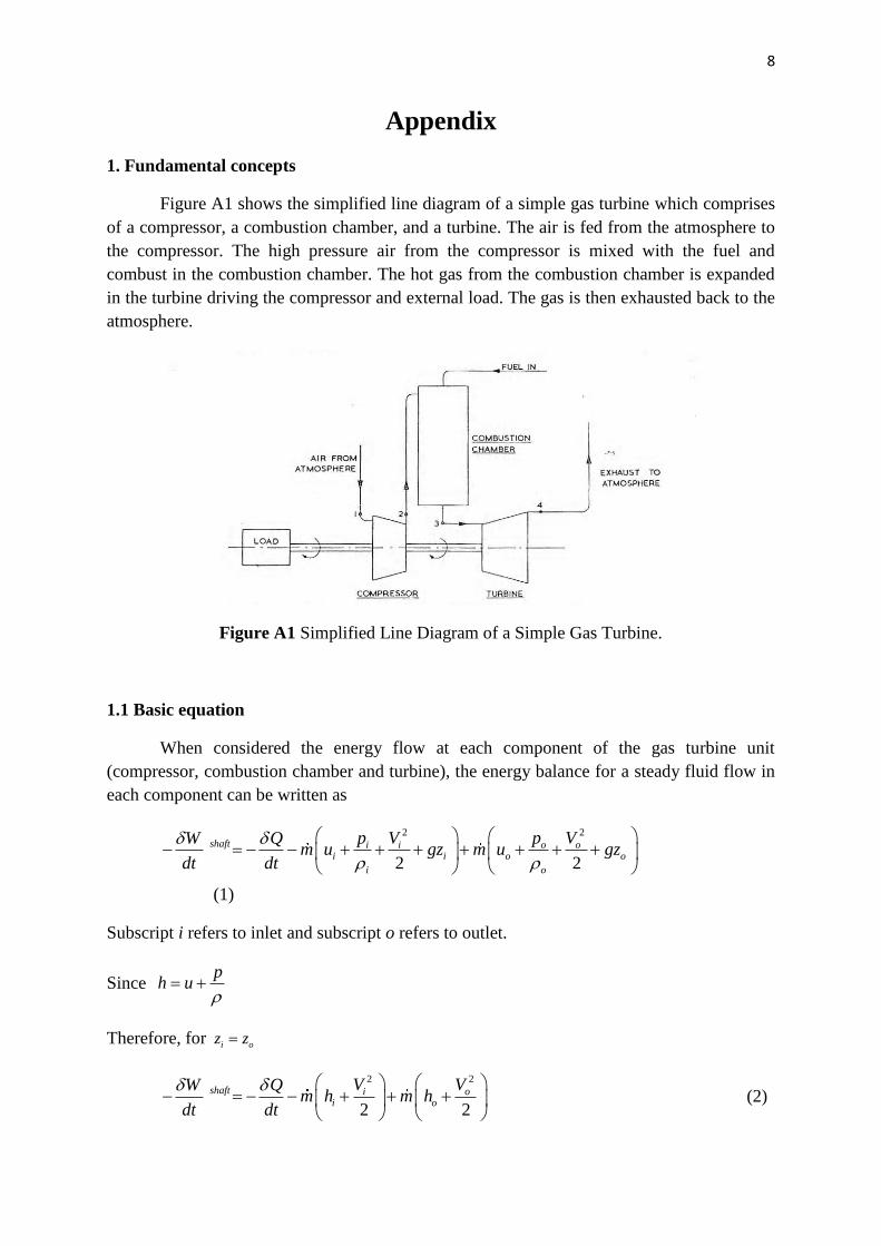
Figure A1 shows the simplified line diagram of a simple gas turbine which comprises
of a compressor, a combustion chamber, and a turbine. The air is fed from the atmosphere to
the compressor. The high pressure air from the compressor is mixed with the fuel and
combust in the combustion chamber. The hot gas from the combustion chamber is expanded
in the turbine driving the compressor and external load. The gas is then exhausted back to the
atmosphere.
Figure A1 Simplified Line Diagram of a Simple Gas Turbine.
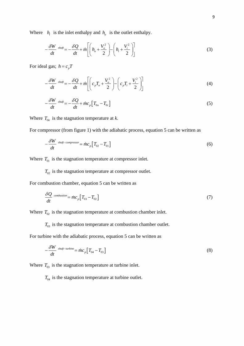
1.1 Basic equation
When considered the energy flow at each component of the gas turbine unit
(compressor, combustion chamber and turbine), the energy balance for a steady fluid flow in
each component can be written as
2 2
2 2
shaft i i o oi i o o
i o
p V p VW Qm u gz m u gz
dt dt
(1)
Subscript i refers to inlet and subscript o refers to outlet.
Since p
h u
Therefore, for i oz z
2 2
2 2
shaft i oi o
V VW Qm h m h
dt dt
(2)
9
Where ih is the inlet enthalpy and
oh is the outlet enthalpy.
2 2
2 2
shaft o io i
V VW Qm h h
dt dt
(3)
For ideal gas; ph c T
2 2
2 2
shaft o ip o p i
V VW Qm c T c T
dt dt
(4)
0 0 shaft
p o i
W Qmc T T
dt dt
(5)
Where 0kT is the stagnation temperature at k.
For compressor (from figure 1) with the adiabatic process, equation 5 can be written as
02 01
shaft compressor
p
Wmc T T
dt
(6)
Where 01T is the stagnation temperature at compressor inlet.
02T is the stagnation temperature at compressor outlet.
For combustion chamber, equation 5 can be written as
03 02 combustion
p
Qmc T T
dt
(7)
Where 02T is the stagnation temperature at combustion chamber inlet.
03T is the stagnation temperature at combustion chamber outlet.
For turbine with the adiabatic process, equation 5 can be written as
04 03
shaft turbine
p
Wmc T T
dt
(8)
Where 03T is the stagnation temperature at turbine inlet.
04T is the stagnation temperature at turbine outlet.
10
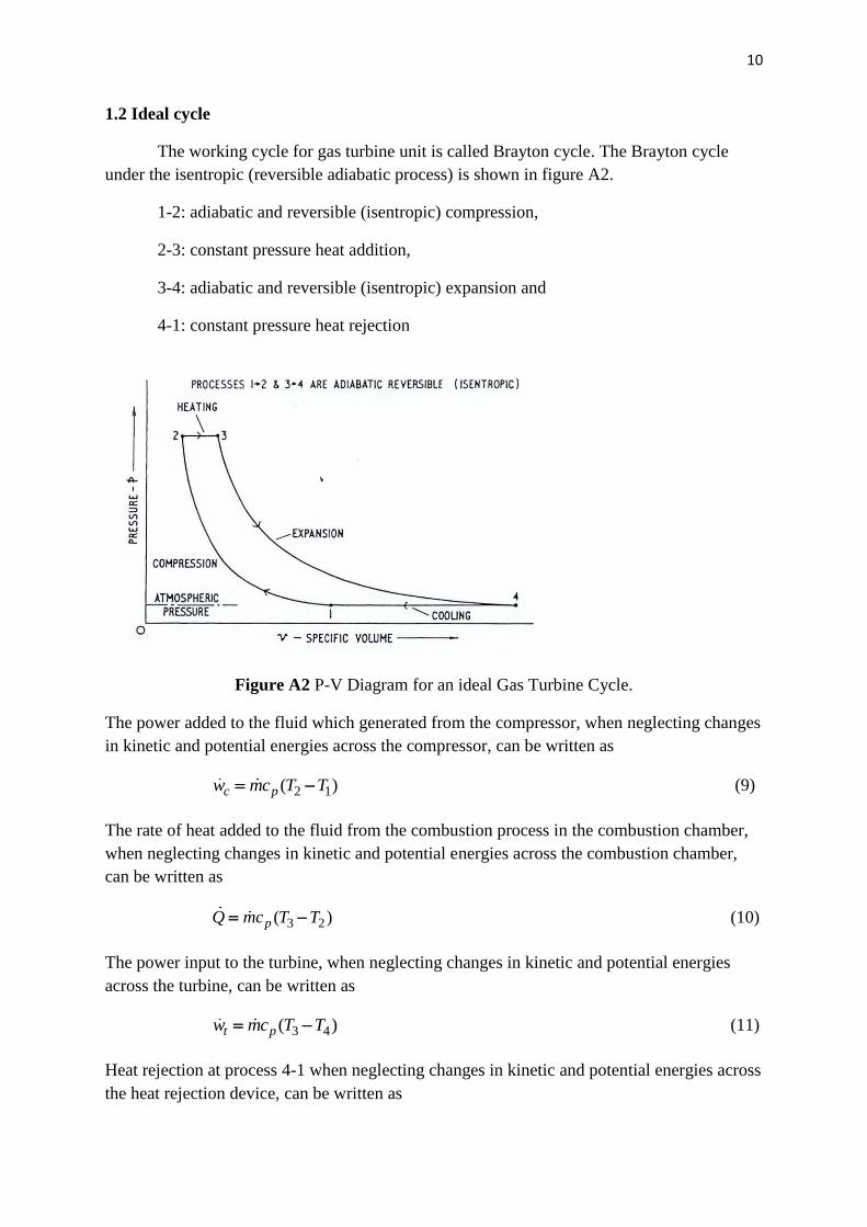
1.2 Ideal cycle
The working cycle for gas turbine unit is called Brayton cycle. The Brayton cycle
under the isentropic (reversible adiabatic process) is shown in figure A2.
1-2: adiabatic and reversible (isentropic) compression,
2-3: constant pressure heat addition,
3-4: adiabatic and reversible (isentropic) expansion and
4-1: constant pressure heat rejection
Figure A2 P-V Diagram for an ideal Gas Turbine Cycle.
The power added to the fluid which generated from the compressor, when neglecting changes
in kinetic and potential energies across the compressor, can be written as
2 1( ) c pw mc T T (9)
The rate of heat added to the fluid from the combustion process in the combustion chamber,
when neglecting changes in kinetic and potential energies across the combustion chamber,
can be written as
3 2( ) pQ mc T T (10)
The power input to the turbine, when neglecting changes in kinetic and potential energies
across the turbine, can be written as
3 4( ) t pw mc T T (11)
Heat rejection at process 4-1 when neglecting changes in kinetic and potential energies across
the heat rejection device, can be written as
11
4 1( ) reject pQ mc T T (12)
1.3 The calculation for the experimental results of the Gas Turbine Unit
For the purpose of understanding the gross behavior of the gas turbine performance,
certain assumptions have been made to simplify the mathematical model of the system. The
assumptions are: steady flow process, pc average between the inlet and outlet condition,
neglecting changes in kinetic and potential energies across the considered component,
neglecting the fuel flow rate when considering the combusted gas flow rate.
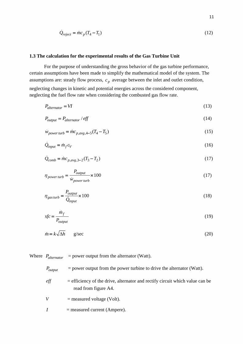
alternatorP VI (13)
/output alternatorP P eff (14)
, ,4 5 4 5( ) power turb p avgw mc T T (15)
input f VQ m c (16)
, ,3 2 3 2( ) comb p avgQ mc T T (17)
100 output
power turbpower turb
P
w (17)
100output
gas turbinput
P
Q (18)
f
output
msfc
P (19)
m k h g/sec (20)
Where alternatorP = power output from the alternator (Watt).
outputP = power output from the power turbine to drive the alternator (Watt).
eff = efficiency of the drive, alternator and rectify circuit which value can be
read from figure A4.
V = measured voltage (Volt).
I = measured current (Ampere).
12
power turbw = power that added to the power turbine (Watt).
inputQ = input heat rate to the system (to the combustion chamber) (Watt).
combQ = added heat from the combustion process in the combustion chamber (Watt).
sfc = specific fuel consumption (kg/(s-Watt)) or (g/(s-Watt)).
power turb = efficiency of the power turbine (%).
gas turb = efficiency of the gas turbine unit (%) (excluding the loss on the
alternator unit).
m = gas flow rate (kg/s) or (g/s).
fm = fuel flow rate (kg/s) or (g/s).
Vc = calorific heat value (kJ/kg) or (kJ/g).
pc = specific heat at constant pressure (J/(kg-K)).
2T = gas generator compressor exit temperature or combustion chamber inlet
temperature (K)
3T = combustion chamber outlet temperature (K)
4T = power turbine inlet temperature (K)
3T = power turbine outlet temperature (K)
k = calibration constant = 11.47 (determined by Cussons and engraved on the
unit).
h = differential pressure reading on the manometer (mmH2O).
Note: Calorific heat value for liquefied petroleum gas (LPG) is 50000 kJ/kg.
13
2. Detail of the Apparatus
The two shaft gas turbine unit is a self contained equipment with a gas generator, power
turbine, loading unit, instrumentation and controls housed on a castor mounted framework.
2.1 Gas Generator
The single shaft generator comprises of a centrifugal compressor, a tubular combustion
chamber and a radial turbine. The compressor and gas generator turbine are close coupled
with the shaft located in a central housing by hydrodynamic bearings.
2.2.1 Compressor
The compressor is a single sided centrifugal type with a multi-bladed aluminum alloy
impeller.
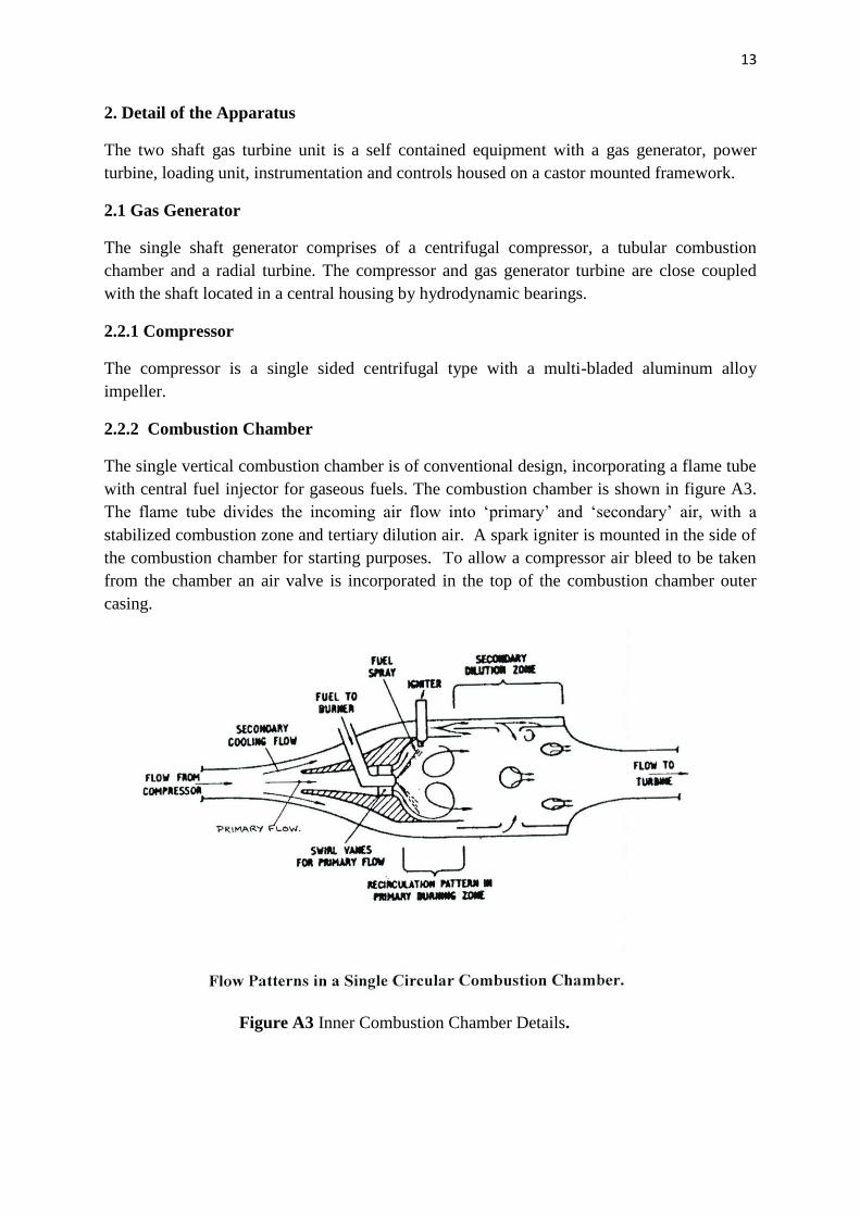
2.2.2 Combustion Chamber
The single vertical combustion chamber is of conventional design, incorporating a flame tube
with central fuel injector for gaseous fuels. The combustion chamber is shown in figure A3.
The flame tube divides the incoming air flow into ‘primary’ and ‘secondary’ air, with a
stabilized combustion zone and tertiary dilution air. A spark igniter is mounted in the side of
the combustion chamber for starting purposes. To allow a compressor air bleed to be taken
from the chamber an air valve is incorporated in the top of the combustion chamber outer
casing.
Figure A3 Inner Combustion Chamber Details.
14
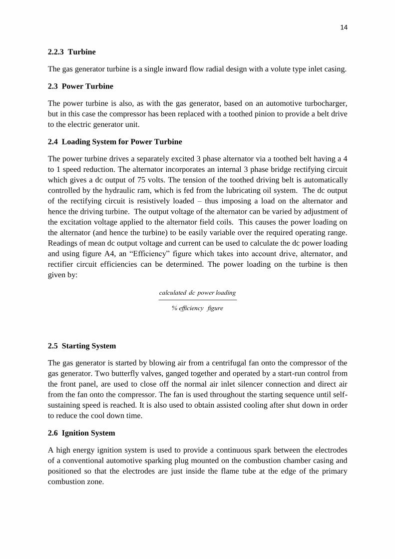
2.2.3 Turbine
The gas generator turbine is a single inward flow radial design with a volute type inlet casing.
2.3 Power Turbine
The power turbine is also, as with the gas generator, based on an automotive turbocharger,
but in this case the compressor has been replaced with a toothed pinion to provide a belt drive
to the electric generator unit.
2.4 Loading System for Power Turbine
The power turbine drives a separately excited 3 phase alternator via a toothed belt having a 4
to 1 speed reduction. The alternator incorporates an internal 3 phase bridge rectifying circuit
which gives a dc output of 75 volts. The tension of the toothed driving belt is automatically
controlled by the hydraulic ram, which is fed from the lubricating oil system. The dc output
of the rectifying circuit is resistively loaded – thus imposing a load on the alternator and
hence the driving turbine. The output voltage of the alternator can be varied by adjustment of
the excitation voltage applied to the alternator field coils. This causes the power loading on
the alternator (and hence the turbine) to be easily variable over the required operating range.
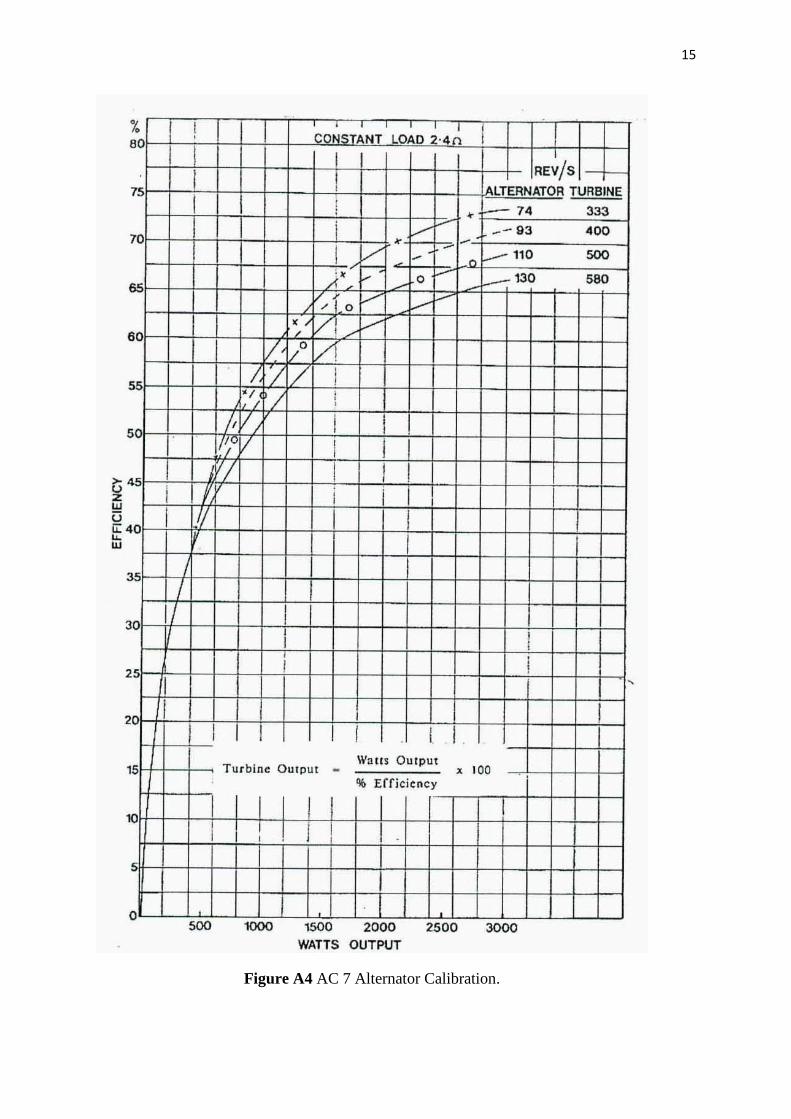
Readings of mean dc output voltage and current can be used to calculate the dc power loading
and using figure A4, an “Efficiency” figure which takes into account drive, alternator, and
rectifier circuit efficiencies can be determined. The power loading on the turbine is then
given by:
figureefficiency%
loadingpowerdccalculated
2.5 Starting System
The gas generator is started by blowing air from a centrifugal fan onto the compressor of the
gas generator. Two butterfly valves, ganged together and operated by a start-run control from
the front panel, are used to close off the normal air inlet silencer connection and direct air
from the fan onto the compressor. The fan is used throughout the starting sequence until self-
sustaining speed is reached. It is also used to obtain assisted cooling after shut down in order
to reduce the cool down time.
2.6 Ignition System
A high energy ignition system is used to provide a continuous spark between the electrodes
of a conventional automotive sparking plug mounted on the combustion chamber casing and
positioned so that the electrodes are just inside the flame tube at the edge of the primary
combustion zone.
15
Figure A4 AC 7 Alternator Calibration.
16
2.7 Lubrication System
The gas generator compressor-turbine and the power turbine bearings are lubricated by a
continuous circulation lubricating system. The system comprises an oil tank, separately
driven gear pump, oil filter and a water cooled oil cooler. The pump draws oil from the tank
and passes it through the full flow oil filter and oil cooler, directly to the main bearings from
which free flowing drain pipes lead back to the oil tank. The system is protected by an oil
pressure switch to shut down the gas turbine in the event of low oil pressure. A small oil
bleed from the main pressure supply pipe is taken to supply the belt tensioning hydraulic ram.
The recommended lubricant is Burmah Castrol “Assurnn T + 10” which is a low viscosity
monograde mineral based detergent oil with an anti-oxidant additive formulated for use with
turbocharged Diesel engines. The normal operating pressure of the lubrication system is 4 to
4.5 bar on starting from cold with the pressure dropping towards 2 bar as the working
temperature in the oil tank rises. The oil cooler ensures that the temperature of the oil fed to
the bearings is maintained at approx. 80C
2.8 Instrumentation.
Instrumentation for both operational and experimental measurement is integrated into the
colored schematic diagram on the instrument and control panel.
2.8.1 Temperature.
From serial number 206 all seven temperatures are measured using type K NiCr/NiA1
thermocouples, whereas previous models used diodes for low temperatures and
thermocouples for high temperatures. The seven temperature channels are:
T1 Air inlet temperature
T2 Gas generator compressor exit temperature
T3 Gas generators turbine inlet temperature
T4 Power turbine inlet temperature
T5 Power turbine exit temperature
Tg Gas (fuel) temperature
To Oil (lubricant) temperature
All the thermocouples are connected via a cold junction compensation unit and break-out unit
to Cussons eight channel thermocouple printed circuit board CBA 219. For each channel
there are two independent outputs, one is for the front panel instrumentation while the other is
a 0-10V dc analogue output available for input to a data logger, computer input or chart
recorder. Three front panel analogue temperature indicators are provided. The three high
temperatures T3, T4 and T5 are connected to a 1000C meter, via cascaded push buttons to
read T4 and T5. With neither button depressed the meter reads T3. Similarly T1, T2 and Tg are
17
connected to a 120C meter which normally reads T2 unless either the T1 or Tg button is
pressed. The oil thermocouple is permanently connected to the 120C oil meter
2.8.2 Pressure
Conventional Bourdon tube pressure gauges are used to measure all pressures other than the
combustion chamber pressure loss (p2 – p3) which is obtained from a differential mercury
manometer. Snubbers are fitted in the P2, P3 and P4 pressure lines.
2.8.3 Air Flow Rate
The air flow is measured at the inlet to the gas generator compressor by a pitot-reverse pitot
tube connected to a differential manometer on the front panel. The air mass flow rate is given
by:
m = k h g/sec
where k = calibration constant (determined by Cussons and engraved on the unit)
h = differential pressure mmH2O
The pitot-reverse pitot method is used as it is not sensitive as a pitot-static tube to flow
pattern distortion effects.
18
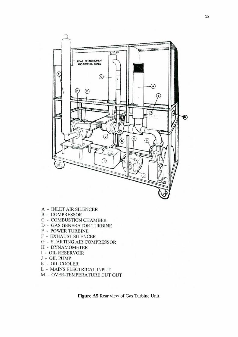
Figure A5 Rear view of Gas Turbine Unit.
19
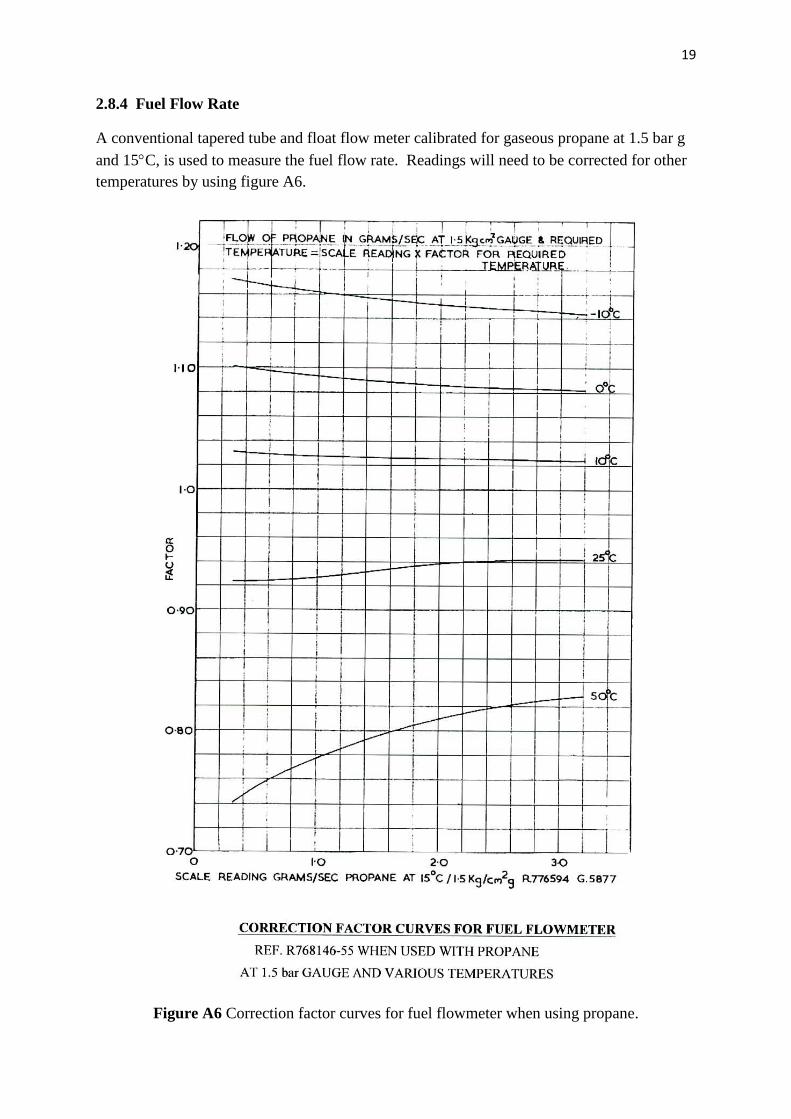
2.8.4 Fuel Flow Rate
A conventional tapered tube and float flow meter calibrated for gaseous propane at 1.5 bar g
and 15C, is used to measure the fuel flow rate. Readings will need to be corrected for other
temperatures by using figure A6.
Figure A6 Correction factor curves for fuel flowmeter when using propane.
20
2.8.5 Rotational Speeds
The gas generator speed and power turbine speed are both measured using two channels of a
four channel frequency to dc conversion printed circuit board CBA 216. The signal for the
gas generator is provided by an inductive pick up sensing a magnetic nut at the compressor
eye, whilst the power turbine speed is obtained by sensing the ac voltage output of the
alternator.
2.8.6 Power Output
The turbine power output can be calculated from the dc voltage applied and current flowing
to the resistive load bank, together with the curve Fig. A4 giving the relationship between dc
power measured and an efficiency factor which takes into account belt, alternator and
rectifying circuit efficiencies.
2.9 Operational Interlocks
A number of operational interlocks or protection devices are built into the service systems to
ensure safe operation of the gas turbine. Pressing the RESET button will energize relay R1
and hence make the fuel, ignition and starting systems operational. The RESET button is a
momentary switch will self latch only if the interlocks associated with the oil pressure switch,
the over temperature cut-out and the starter blower motor thermal trip are correctly
positioned.
2.9.1 Turbine Over Temperature
A comparator circuit contained within the eight channel temperature printed circuit board
continuously monitors the turbine inlet temperature T3. In the event of T3 exceeding the limit
set by the comparator circuit, relay R1 will be unlatched thus switching off the ignition
system and starting blower. The fuel shut-off solenoid valve will also be de-energized.
2.9.2 Loss of Oil Pressure
An oil pressure switch monitors the pressure of the oil used to supply the oil circuit and if its
pressure falls too low the oil pressure switch opens and unlatches the relay R1, thus shutting
down the engine.
2.9.3 Starter Blower Motor
The induction motor which drives the starter blower is protected by a thermal trip in the
blower motor contactor. Auxiliary contacts on the contactor are used to enable relay R1 thus
providing protection should the motor trip during operation.
2.9.4 Oil Pump Motor
The induction motor which drives the oil pump is protected by a thermal trip in the oil pump
motor contactor.
2.9.5 Electrical Power Failure
21
The system is designed to fail safe in that should electrical power be lost in any art of the
protection system or to the unit as a whole, then relay R1 will unlatch and the fuel solenoid
valve will close, thus causing the shut down of the equipment.
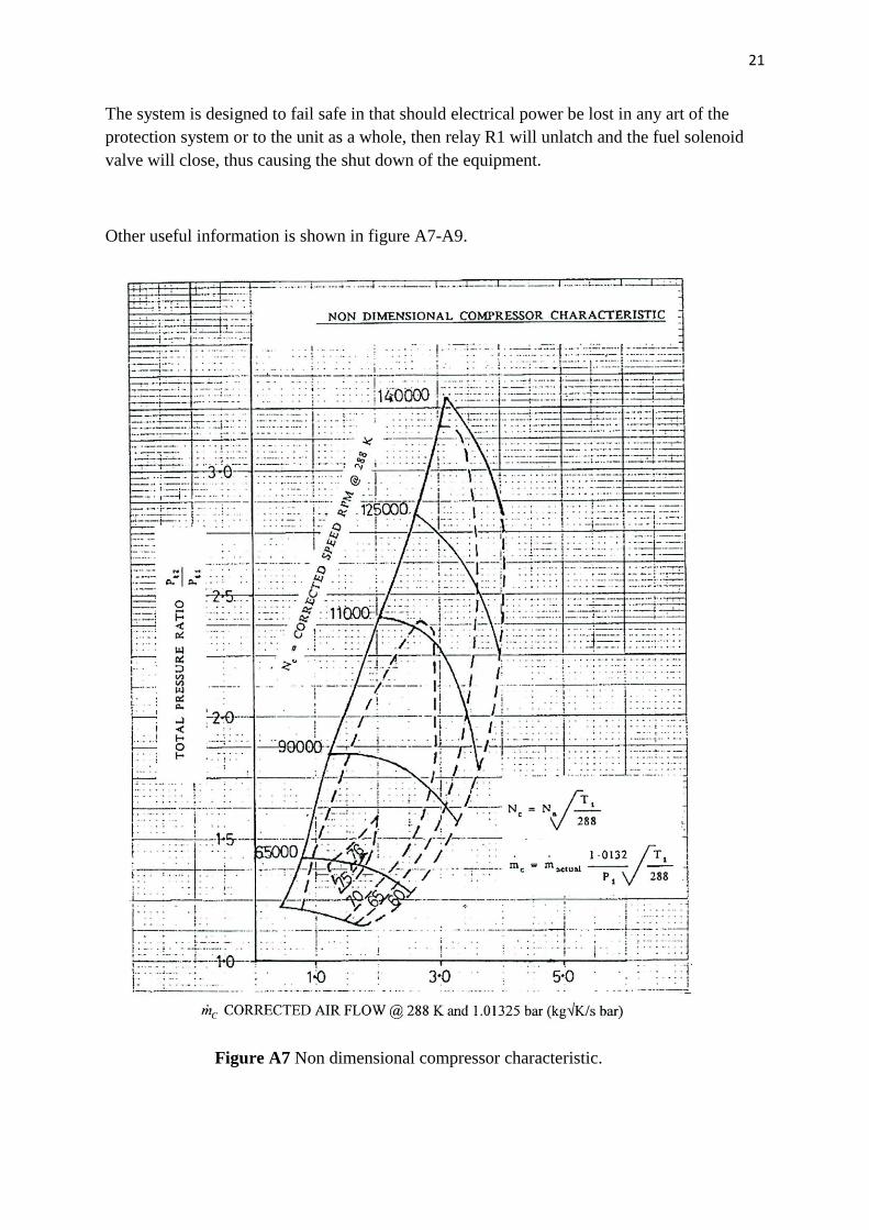
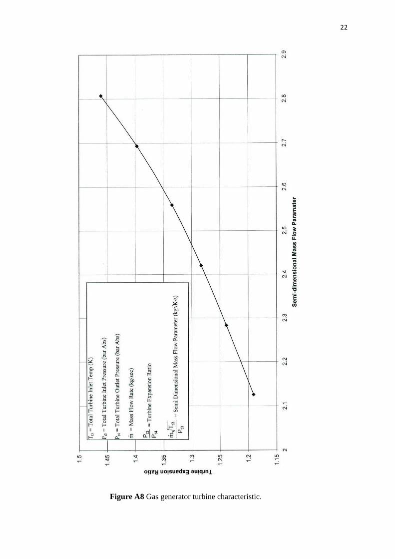
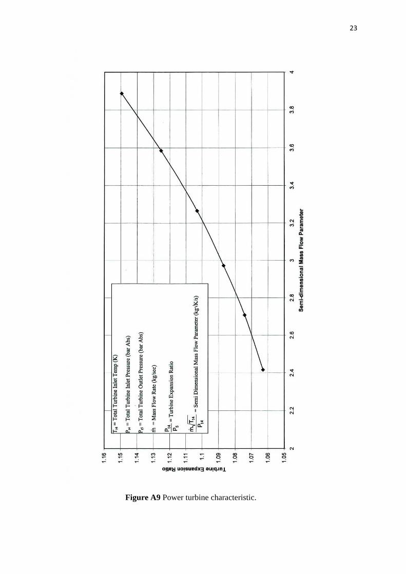
Other useful information is shown in figure A7-A9.
Figure A7 Non dimensional compressor characteristic.
22
Figure A8 Gas generator turbine characteristic.
23
Figure A9 Power turbine characteristic.
24
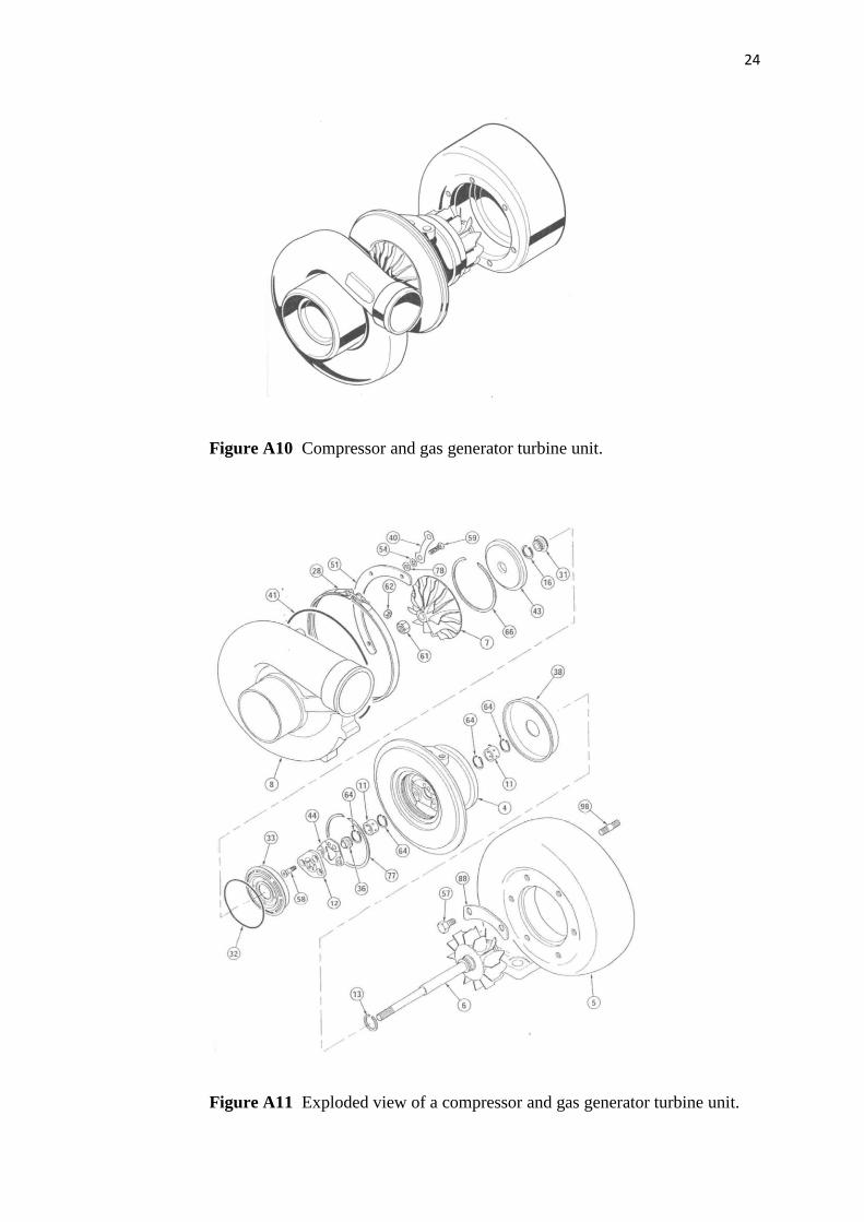
Figure A10 Compressor and gas generator turbine unit.
Figure A11 Exploded view of a compressor and gas generator turbine unit.
25
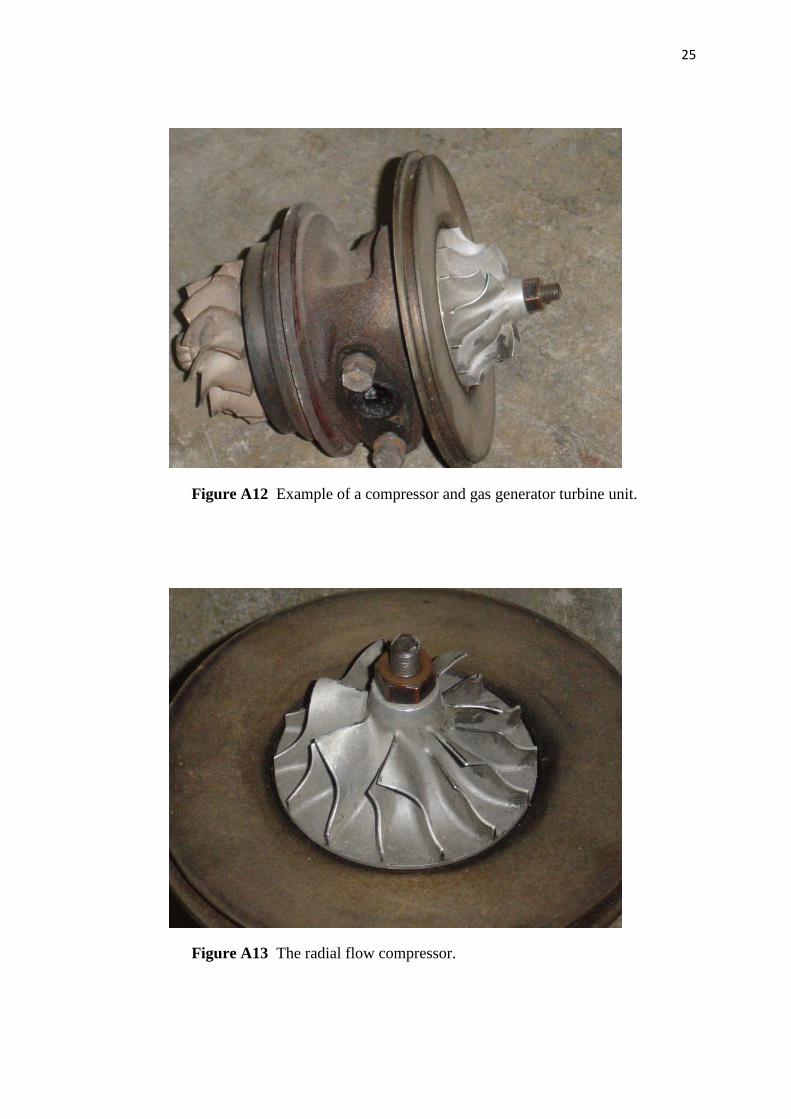
Figure A12 Example of a compressor and gas generator turbine unit.
Figure A13 The radial flow compressor.
26
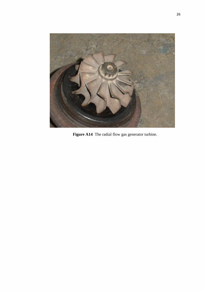
Figure A14 The radial flow gas generator turbine.

27
Table A1 Thermo-Physical Properties of Air (100-1000 K at 1 atm) [3]
28
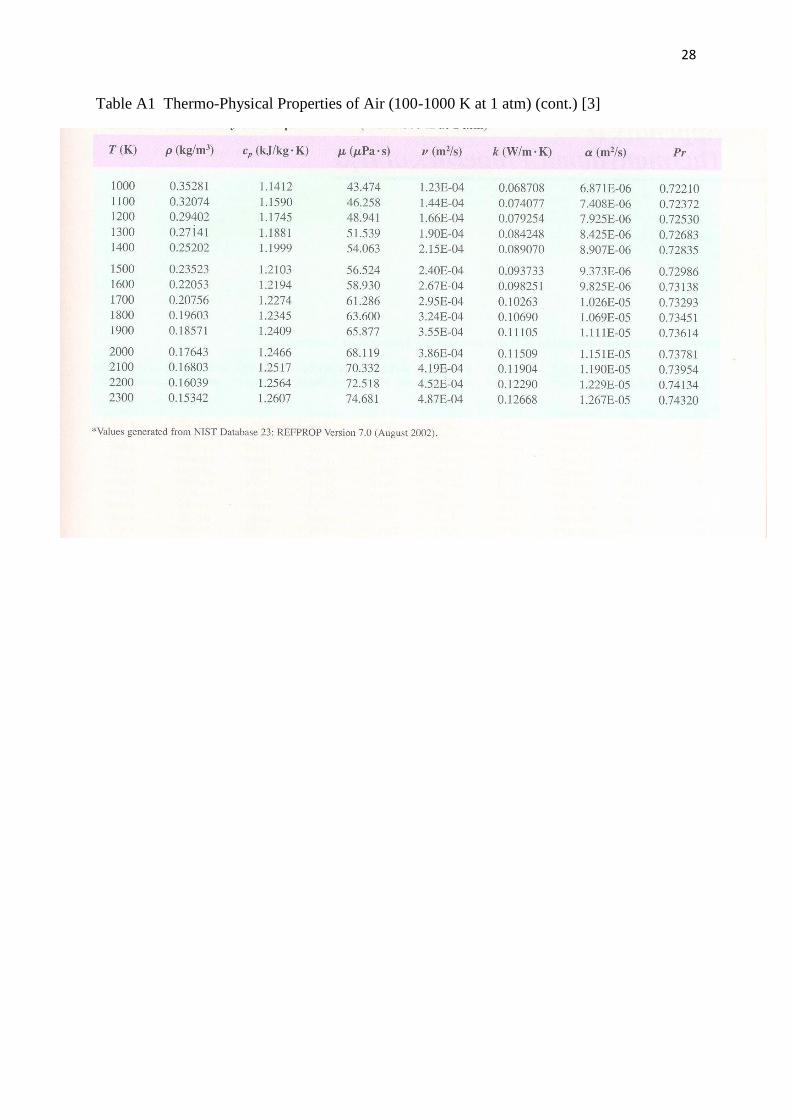
Table A1 Thermo-Physical Properties of Air (100-1000 K at 1 atm) (cont.) [3]