Embed Size (px)
Citation preview
8/4/2019 21 30 Solutions
http://slidepdf.com/reader/full/21-30-solutions 1/6
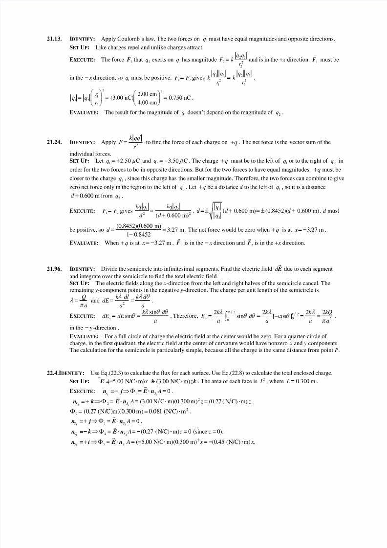
21.13. IDENTIFY: Apply Coulomb’s law. The two forces on3
q must have equal magnitudes and opposite directions.
SET UP: Like charges repel and unlike charges attract.
EXECUTE: The force2
F that2
q exerts on 3q has magnitude
2 3
2 2
2
q qF k
r and is in the + x direction.
1 F must be
in the x direction, so 1q must be positive. 1 2
F F gives1 3 2 3
2 2
1 2
q q q qk k
r r .
2 2
11 2
2
2.00 cm(3.00 nC) 0.750 nC4.00 cm
r q qr
.
EVALUATE: The result for the magnitude of 1q doesn’t depend on the magnitude of
2q .
21.24. IDENTIFY: Apply2
k qqF
r to find the force of each charge on q . The net force is the vector sum of the
individual forces.
SET UP: Let 12.50 Cq and 2 3.50 Cq . The charge q must be to the left of 1q or to the right of
2q in
order for the two forces to be in opposite directions. But for the two forces to have equal magnitudes, q must be
closer to the charge 1q , since this charge has the smaller magnitude. Therefore, the two forces can combine to give
zero net force only in the region to the left of 1q . Let q be a distance d to the left of 1
q , so it is a distance
0.600 md from 2q .
EXECUTE: 1 2F F gives
1 2
2 2( 0.600 m)
kq q kq q
d d .
1
2
( 0.600 m) (0.8452)( 0.600 m)q
d d d q
. d must
be positive, so(0.8452)(0.600 m)
3.27 m1 0.8452
d . The net force would be zero when q is at 3.27 m x .
EVALUATE: When q is at 3.27 m x ,1
F is in the x direction and2
F is in the + x direction.
21.96. IDENTIFY: Divide the semicircle into infinitesimal segments. Find the electric field d E due to each segment
and integrate over the semicircle to find the total electric field.
SET UP: The electric fields along the x-direction from the left and right halves of the semicircle cancel. The
remaining y-component points in the negative y-direction. The charge per unit length of the semicircle isQ
aand
2
k dl k d dE
a a.
EXECUTE: sinsin y
k d dE dE
a. Therefore,
22
0 20
2 2 2 2sin [ cos ] y
k k k kQ E d
a a a a,
in the -direction y .
EVALUATE: For a full circle of charge the electric field at the center would be zero. For a quarter-circle of
charge, in the first quadrant, the electric field at the center of curvature would have nonzero x and y components.
The calculation for the semicircle is particularly simple, because all the charge is the same distance from point P.
22.4.IDENTIFY: Use Eq.(22.3) to calculate the flux for each surface. Use Eq.(22.8) to calculate the total enclosed charge.
SET UP: ˆ ˆ( 5.00 N/C m) (3.00 N/C m) x z E = i+ k . The area of each face is 2 L , where 0.300 m L .
EXECUTE:1 11
ˆˆ ˆ 0s S A n = j E n .
2 2
2
2ˆˆ ˆ (3.00 N C m)(0.300 m) (0.27 ( N C) m)S S A z z n = k E n .
2
2(0.27 (N/C)m)(0.300 m) 0.081 (N/C) m .
3 33ˆˆ ˆ 0S S A n = j E n .
4 44ˆˆ ˆ (0.27 (N/C) m) 0 (since 0).S S A z z n = k E n
5 5
2
5ˆ
ˆ ˆ ( 5.00 N/C m)(0.300 m) (0.45 (N/C) m) .S S A x x n = i E n
8/4/2019 21 30 Solutions
http://slidepdf.com/reader/full/21-30-solutions 2/6
2
5 (0.45 (N/C) m)(0.300 m) (0.135 (N/C) m ).
6 66ˆˆ ˆ (0.45 (N/C) m) 0 (since 0).S S A x x n = i E n
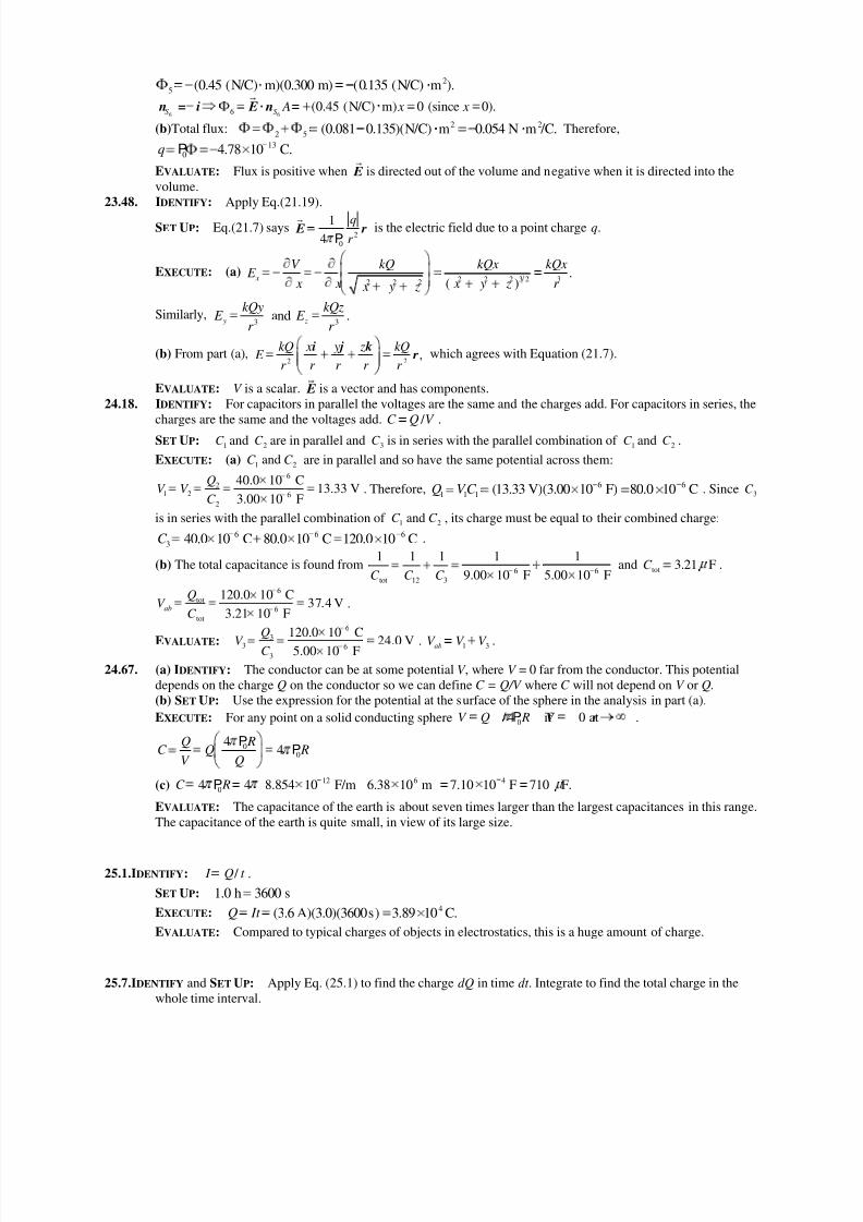
(b)Total flux: 2 2
2 5 (0.081 0.135)(N/C) m 0.054 N m /C. Therefore,13
0 4.78 10 C.q P
EVALUATE: Flux is positive when E is directed out of the volume and negative when it is directed into the
volume.
23.48. IDENTIFY: Apply Eq.(21.19).
SET UP: Eq.(21.7) says2
0
1ˆ
4
q
r E r
Pis the electric field due to a point charge q.
EXECUTE: (a) 2 2 2 3 2 32 2 2
.( )
x
V kQ kQx kQx E
x x x y z r x y z
Similarly,3 3
and . y z
kQy kQz E E
r r
(b) From part (a),2 2
ˆ ˆ ˆ
ˆ,kQ x y z kQ
E r r r r r
i j k r which agrees with Equation (21.7).
EVALUATE: V is a scalar. E is a vector and has components.
24.18. IDENTIFY: For capacitors in parallel the voltages are the same and the charges add. For capacitors in series, the
charges are the same and the voltages add. / C Q V .
SET UP: 1
C and 2C are in parallel and 3
C is in series with the parallel combination of 1
C and 2C .
EXECUTE: (a) 1 2andC C are in parallel and so have the same potential across them:
6
2
1 2 6
2
40.0 10 C13.33 V
3.00 10 F
QV V
C . Therefore, 6 6
1 1 1 (13.33 V)(3.00 10 F) 80.0 10 CQ V C . Since 3C
is in series with the parallel combination of 1 2andC C , its charge must be equal to their combined charge:6 6 6
3 40.0 10 C 80.0 10 C 120.0 10 CC .
(b) The total capacitance is found from6 6
tot 12 3
1 1 1 1 1
9.00 10 F 5.00 10 FC C C and tot
3.21 FC .
6
tot
6
tot
120.0 10 C37.4 V
3.21 10 Fab
QV
C .
EVALUATE: 6
3
3 6
3
120.0 10 C
24.0 V5.00 10 F
Q
V C . 1 3abV V V .
24.67. (a) IDENTIFY: The conductor can be at some potential V , where V = 0 far from the conductor. This potential
depends on the charge Q on the conductor so we can define C = Q/V where C will not depend on V or Q.
(b) SET UP: Use the expression for the potential at the surface of the sphere in the analysis in part (a).
EXECUTE: For any point on a solid conducting sphere 0 / 4 if 0 at .V Q R V r P
00
44
Q RC Q R
V Q
PP
(c)12 6 4
04 4 8.854 10 F/m 6.38 10 m 7.10 10 F 710 F.C RP
EVALUATE: The capacitance of the earth is about seven times larger than the largest capacitances in this range.
The capacitance of the earth is quite small, in view of its large size.
25.1.IDENTIFY: / I Q t .
SET UP: 1.0 h 3600 s
EXECUTE: 4(3.6 A)(3.0)(3600s) 3.89 10 C.Q It
EVALUATE: Compared to typical charges of objects in electrostatics, this is a huge amount of charge.
25.7.IDENTIFY and SET UP: Apply Eq. (25.1) to find the charge dQ in time dt . Integrate to find the total charge in the
whole time interval.
8/4/2019 21 30 Solutions
http://slidepdf.com/reader/full/21-30-solutions 3/6

8/4/2019 21 30 Solutions
http://slidepdf.com/reader/full/21-30-solutions 4/6
SET UP: Since the straight sections produce no field at P, the field at P is 0
4
I B
R.
EXECUTE: 0
4
I B
R. The direction of B is given by the right-hand rule: B is directed into the page.
EVALUATE: For a quarter-circle section of wire the magnetic field at its center of curvature is 0
8
I B
R.
28.31. IDENTIFY: Calculate the magnetic field vector produced by each wire and add these fields to get the total field.
SET UP: First consider the field at P produced by the current1
I in the upper semicircle of wire. See Figure
28.31a.
Consider the three parts of this wire
a: long straight section,
b: semicircle
c: long, straight section
Figure 28.31a
Apply the Biot-Savart law 0 0
2 3
ˆ
4 4
Id Id d
r r
l r l r B = = to each piece.
EXECUTE: part a See Figure 28.31b.
0,d l r =
so 0dB
Figure 28.31b
The same is true for all the infinitesimal segments that make up this piece of the wire, so B = 0 for this piece.
part c See Figure 28.31c.
0,d l r =
so 0 and 0dB B for this piece.
Figure 28.31c
part b See Figure 28.31d.
d l r is directed into the paper for all infinitesimal
segments that make up this semicircular piece, so B
is directed into the paper and B dB(the vector sum
of the d B is obtained by adding their magnitudes
since they are in the same direction).
Figure
28.31d
sin .d r dll r The angle between and is 90 and ,d r Rl r the radius of the semicircle. Thus d R dll r
0 0 1 0 1
3 3 24 4 4
I d I R I dB dl dl
r R R
l r
0 1 0 1 0 1
2 2( )
4 4 4
I I I B dB dl R
R R R
(We used that dl is equal to , R the length of wire in the semicircle.) We have shown that the two straight
sections make zero contribution to , B so 1 0 1 / 4 B I R and is directed into the page.
For current in the direction shown in
Figure 28.31e, a similar analysis gives
2 0 2 / 4 , B I R out of the paper
Figure 28.31e
1 2and B B are in opposite directions, so the magnitude of the net field at P is0 1 2
1 2.
4
I I B B B
R
EVALUATE: When 1 2 , 0. I I B
8/4/2019 21 30 Solutions
http://slidepdf.com/reader/full/21-30-solutions 5/6
28.37. IDENTIFY: Apply Ampere’s law.
SET UP: To calculate the magnetic field at a distance r from the center of the cable, apply Ampere’s law to a
circular path of radius r . By symmetry, (2 )d B r B l ú for such a path.
EXECUTE: (a) For 0
encl 0 0, 2 .
2
μ I a r b I I d μ I B πr μ I B
πr B l ú
(b) For ,r c the enclosed current is zero, so the magnetic field is also zero.
EVALUATE: A useful property of coaxial cables for many applications is that the current carried by the cable
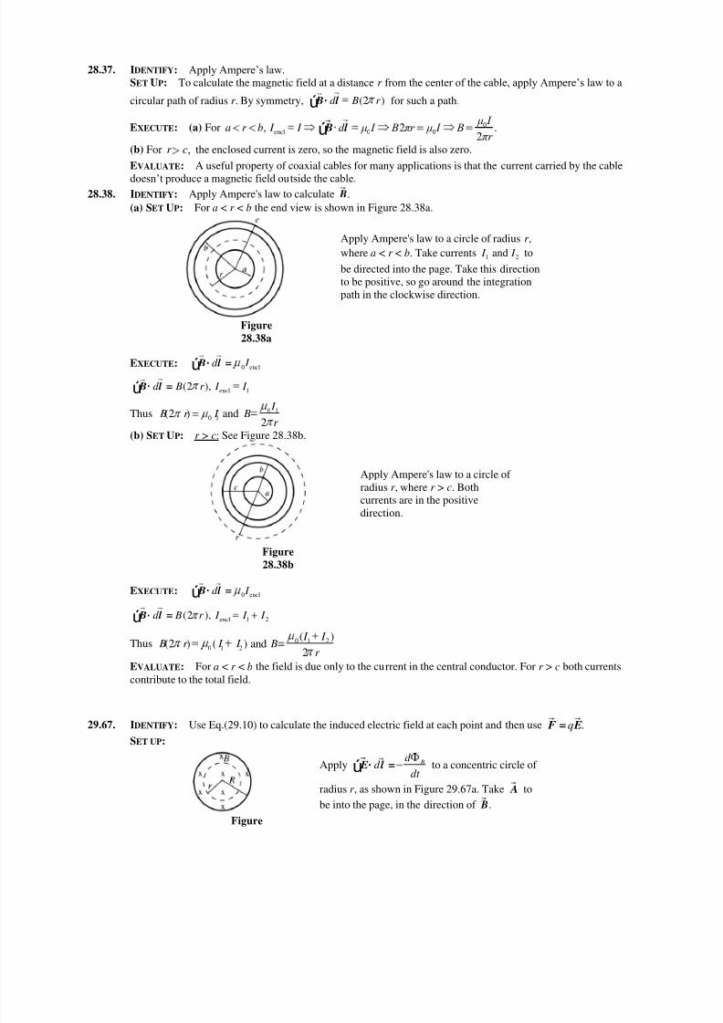
doesn’t produce a magnetic field outside the cable. 28.38. IDENTIFY: Apply Ampere's law to calculate . B
(a) SET UP: For a < r < b the end view is shown in Figure 28.38a.
Apply Ampere's law to a circle of radius r ,
where a < r < b. Take currents 1 2and I I to
be directed into the page. Take this direction
to be positive, so go around the integration
path in the clockwise direction.
Figure
28.38a
EXECUTE: 0 encld I B l =ú
encl 1(2 ),d B r I I B l =ú
Thus 0 1
0 1(2 ) and
2
I B r I B
r
(b) SET UP: r > c: See Figure 28.38b.
Apply Ampere's law to a circle of
radius r , where r > c. Both
currents are in the positive
direction.
Figure
28.38b
EXECUTE: 0 encld I B l =ú
encl 1 2(2 ),d B r I I I B l =ú
Thus 0 1 2
0 1 2
( )(2 ) ( ) and
2
I I B r I I B
r
EVALUATE: For a < r < b the field is due only to the current in the central conductor. For r > c both currents
contribute to the total field.
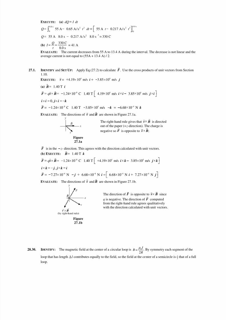
29.67. IDENTIFY: Use Eq.(29.10) to calculate the induced electric field at each point and then use .q F = E
SET UP: Apply Bd
d dt
E l =ú to a concentric circle of
radius r , as shown in Figure 29.67a. Take A to
be into the page, in the direction of . B
Figure
8/4/2019 21 30 Solutions
http://slidepdf.com/reader/full/21-30-solutions 6/6
29.67a
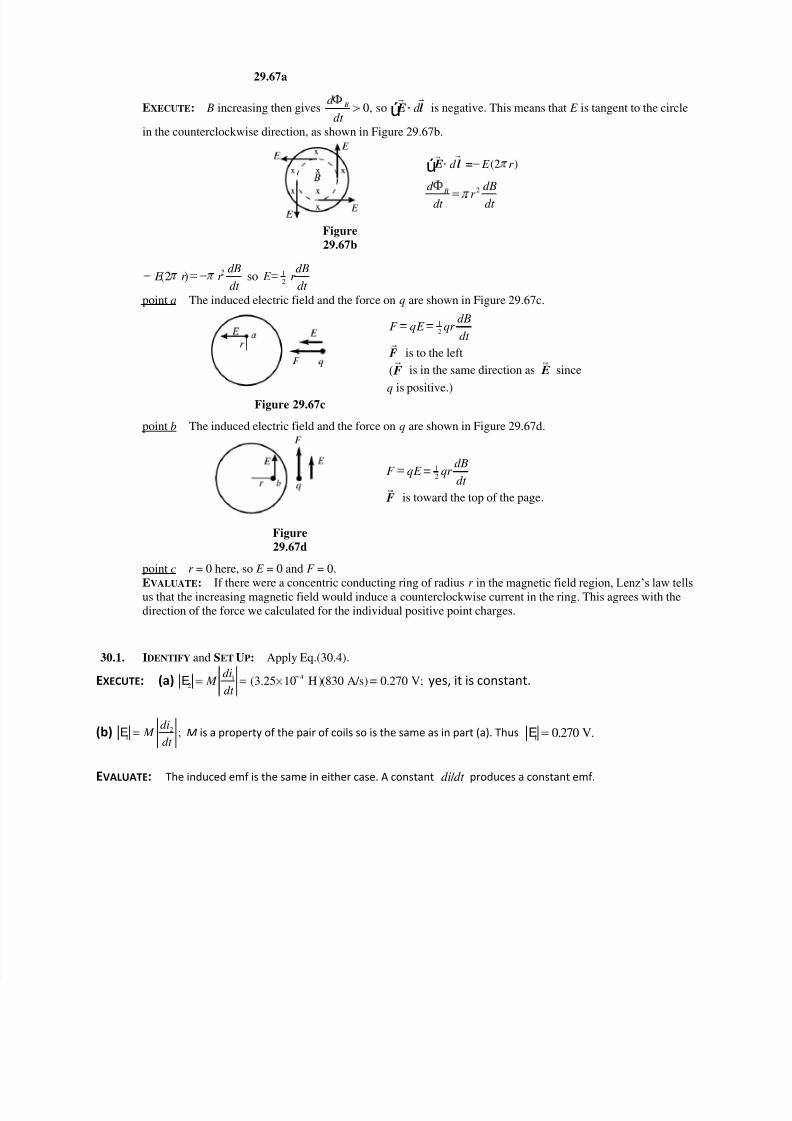
EXECUTE: B increasing then gives 0, so Bd d
dt E l ú is negative. This means that E is tangent to the circle
in the counterclockwise direction, as shown in Figure 29.67b.
(2 )d E r E l =ú
2 Bd dB
r dt dt
Figure
29.67b
2 1
2(2 ) so
dB dB E r r E r
dt dt
point a The induced electric field and the force on q are shown in Figure 29.67c.
1
2
dBF qE qr
dt
F is to the left
( F is in the same direction as E since
q is positive.)Figure 29.67c
point b The induced electric field and the force on q are shown in Figure 29.67d.
1
2
dBF qE qr
dt
F is toward the top of the page.
Figure
29.67d
point c r = 0 here, so E = 0 and F = 0.
EVALUATE: If there were a concentric conducting ring of radius r in the magnetic field region, Lenz’s law tells
us that the increasing magnetic field would induce a counterclockwise current in the ring. This agrees with the
direction of the force we calculated for the individual positive point charges.
30.1. IDENTIFY and SET UP: Apply Eq.(30.4).
EXECUTE: (a) 412
(3.25 10 H)(830 A/s) 0.270 V;di
M dt
E yes, it is constant.
(b) 21
;di
M dt
E M is a property of the pair of coils so is the same as in part (a). Thus1 0.270 V.E
EVALUATE: The induced emf is the same in either case. A constant / di dt produces a constant emf.