Embed Size (px)
Citation preview
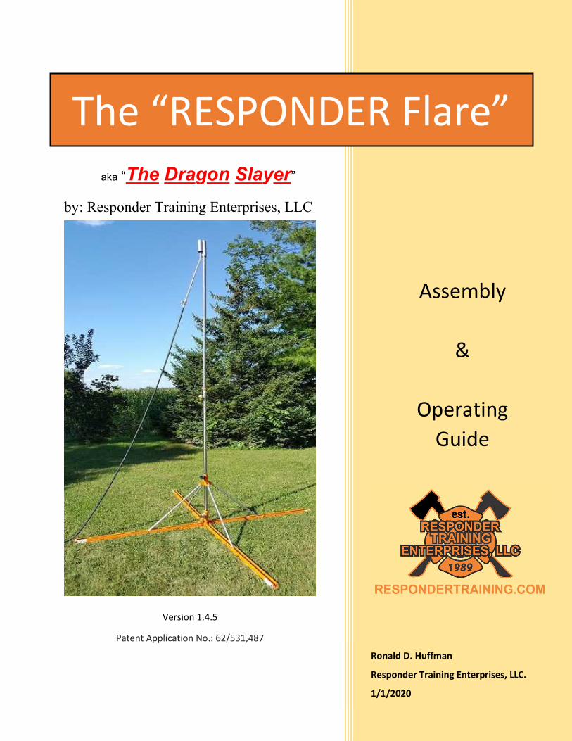
aka “The Dragon Slayer”
Assembly
&
Operating Guide
Ronald D. Huffman
Responder Training Enterprises, LLC.
1/1/2020
The “RESPONDER Flare”
Version 1.4.5
Patent Application No.: 62/531,487
by: Responder Training Enterprises, LLC

Page 1 of 11
Thank you for purchasing our 1-inch propane flaring system. My intention in creating and producing this product was to provide response and service organizations with a quality tool that would exceed anything else currently on the market and last the owner for years to come.
As a career and volunteer firefighter, I know how important it is respond with the tools you need to get the job done quickly and safely. The Responder Flare was designed to be set up without the need for tools. It’s designed to operate on flat and unlevel surfaces and provide you with flow capabilities unlike any other commercially available flaring system. The Responder Flare has been designed to operate on incidents that require limited flow capabilities and support the flow capacities needed for highway, rail and bulk storage facilities.
The option to flow liquid or vapor using 1-inch components can provide your agency the ability to start forcing a tank into auto refrigeration or lower the liquid level much quicker than smaller systems.
Dubbed the “Dragon Slayer” by one of our customers, this flaring system has an industrial look and feel due to its quality, solid, heavy duty construction.
If you have any questions, concerns or comments please contact me.
Be safe brothers and sisters
Ronald D. Huffman Owner, Responder Training Enterprises, LLC (765) 524-4848 Mobile
Designer, manufacturer and distributor of this and many other propane response tools and soon we will be including CNG options as well.
Call me anytime for response tools or our one of a kind propane training course, “Propane Response – 101 to Advanced Tactics”
Photo of the “Dragon” looking down on me during a Propane Live Fire class taught in Greenfield IN.

Page 2 of 11
Table of Contents Specifications ............................................................................................................... 3
Set-Up and Assembly ...................................................................................................... 4
Flaring Operations ........................................................................................................... 5
Adjustable Base Option ............................................................................................... 6
Final Inspection Before Ignition .................................................................................... 6
Ignition ......................................................................................................................... 6
Pilot Burner Supply Change ......................................................................................... 7
Option #1 .................................................................................................................. 7
Option #2 .................................................................................................................. 7
Terminating Operations and Flare Storage ..................................................................... 8
Warranty: ......................................................................................................................... 9
Manufacturer Liability Limitation: ..................................................................................... 9
READ AND FOLLOW ALL SAFETY INFORMATION
IF YOU ARE UNSURE STOP!
REREAD THE INSTRUCTIONS OR
CONTACT RESPONDER TRAINING ENTERPRISES FOR ASSISTANCE

Page 3 of 11
Specifications Name: “Responder Flare” aka “The Dragon Slayer” SKU: FLARE-SSRF1 Flare Stack: 1 inch 304 Stainless Steel Flare Height: 10 feet Footprint: 4 legs = 64 Square Foot Base: Adjustable for uneven surface Inlet: 1 inch Outlet: 1 inch Flow Capacity: 1300+ GPH BTU: 91,000,000 +
Clearance Required: Incident specific, based on radiant heat produced. At full flow, a minimum of 100-foot radius and 400-foot vertical is recommended.
Product: LPG (vapor or liquid) Use with any other material voids all warranties expressed or implied unless specifically approved by the manufacture.
Highlighted text: Indicates special attention should be applied to the information provided
IMPORTANT: Prior to operating the Responder Flare and any of its accessories you must fully read, understand and follow the information in this document. IF YOU ARE UNSURE OF HOW TO CONDUCT ANY FUNCTION OR OPERATION “STOP”, CONSULT THIS DOCUMENT OR CONTACT RESPONDER TRAINING ENTERPRISES, LLC. FOR CLARIFICATION.
FLARING OPERATIONS ARE INHERENTLY DANGEROUS. Failure to follow the appropriate safety measures could result in serious injury or death. In addition to this product literature all appropriate local, State and Federal codes, regulations and guidelines must be identified and followed at all times.
Only personnel that have received proper training and understand the proper use of this product(s) and associated equipment should operate the Responder Flare and/or any of its accessories during training or incident response.
WEAR APPROVED PPE INCLUDING: GLOVES, BODY, HANDS, EYES and RESPIRATORY PROTECTION DURING SET-UP AND OPERATIONS.
A copy of this document should be kept with the flare at all times
Read before using the warranty, liability and additional special information found at the end of this document.

Page 4 of 11
Set-Up and Assembly
1. Open the storage bag and unpack all the components.
2. Stand the base section and loosen the slide lock (A).
3. While holding the top of the base steady and maintaining control, slowly lower Slide (B) and allow the legs to extend.
4. Slide the Pilot Burner Assembly (C) onto the upper flare stack and down to the stop collar (D).
5. Insure that the Pilot Burner control valve (E) is in the off position as pictured.
6. Remove the brass male ACME protective cap (F) and attach the upper section of the flare stack with the pilot burner to the base section (G) (female ACME).
7. Stand the flare assembly.
(A)
(B)
(C)
(D)
(E)
Note: Use caution to ensure that the upper section does not tip and fall during this process. If multiple personnel are available connect the upper and base sections while holding them near horizontal.
(F)
(G)
CAUTION: Pinch/Scissor points exist. Moving parts can create a pinch or cutting action, ensure that no body parts are placed at any location where two components cross or may cause injury.
Page 5 of 11
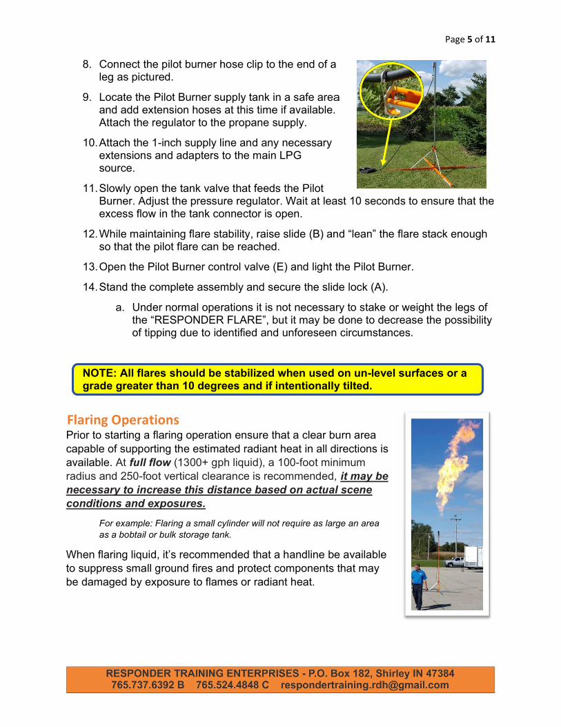
8. Connect the pilot burner hose clip to the end of a leg as pictured.
9. Locate the Pilot Burner supply tank in a safe area and add extension hoses at this time if available. Attach the regulator to the propane supply.
10. Attach the 1-inch supply line and any necessary extensions and adapters to the main LPG source.
11. Slowly open the tank valve that feeds the Pilot Burner. Adjust the pressure regulator. Wait at least 10 seconds to ensure that the excess flow in the tank connector is open.
12. While maintaining flare stability, raise slide (B) and “lean” the flare stack enough so that the pilot flare can be reached.
13. Open the Pilot Burner control valve (E) and light the Pilot Burner.
14. Stand the complete assembly and secure the slide lock (A).
a. Under normal operations it is not necessary to stake or weight the legs of the “RESPONDER FLARE”, but it may be done to decrease the possibility of tipping due to identified and unforeseen circumstances.
NOTE: All flares should be stabilized when used on un-level surfaces or a grade greater than 10 degrees and if intentionally tilted.
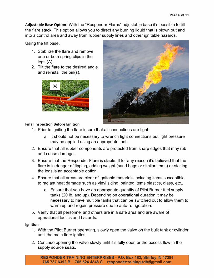
Flaring Operations Prior to starting a flaring operation ensure that a clear burn area capable of supporting the estimated radiant heat in all directions is available. At full flow (1300+ gph liquid), a 100-foot minimum radius and 250-foot vertical clearance is recommended, it may be necessary to increase this distance based on actual scene conditions and exposures.
For example: Flaring a small cylinder will not require as large an area as a bobtail or bulk storage tank.
When flaring liquid, it’s recommended that a handline be available to suppress small ground fires and protect components that may be damaged by exposure to flames or radiant heat.
Page 6 of 11
Adjustable Base Option: With the “Responder Flares” adjustable base it’s possible to tilt the flare stack. This option allows you to direct any burning liquid that is blown out and into a control area and away from rubber supply lines and other ignitable hazards.
Using the tilt base,
1. Stabilize the flare and remove one or both spring clips in the legs (A).
2. Tilt the flare to the desired angle and reinstall the pin(s).
Final Inspection Before Ignition
1. Prior to igniting the flare insure that all connections are tight.
a. It should not be necessary to wrench tight connections but light pressure may be applied using an appropriate tool.
2. Ensure that all rubber components are protected from sharp edges that may rub and cause damage.
3. Ensure that the Responder Flare is stable. If for any reason it’s believed that the flare is in danger of tipping, adding weight (sand bags or similar items) or staking the legs is an acceptable option.
4. Ensure that all areas are clear of ignitable materials including items susceptible to radiant heat damage such as vinyl siding, painted items plastics, glass, etc..
a. Ensure that you have an appropriate quantity of Pilot Burner fuel supply tanks (20 lb. and up). Depending on operational duration it may be necessary to have multiple tanks that can be switched out to allow them to warm up and regain pressure due to auto-refrigeration.
5. Verify that all personnel and others are in a safe area and are aware of operational tactics and hazards.
Ignition 1. With the Pilot Burner operating, slowly open the valve on the bulk tank or cylinder
until the main flare ignites.
2. Continue opening the valve slowly until it’s fully open or the excess flow in the supply source seats.
(A)

Page 7 of 11
a. If the excess flow seats, identify the valve location (for example: half open) and then shut OFF the BULK SUPPLY valve.
i. Wait until the excess flow valve re-opens (usually indicated by a single click).
b. Slowly re-open the tank valve to a point just before the excess flow shuts.
Pilot Burner Supply Change Due to the limited capacity or auto-refrigeration of the Pilot Burners supply tank it may be necessary to switch out the supply during flaring operations if it is maintained during sustained operations.
Option #1 1) To maintain an operating flare, slightly reduce the supply to the main flare
to ensure that excess flow does not shut while the Pilot Burner supply is replaced,
2) Turn off the Pilot Burner supply and switch out the tank.
3) Slowly open the Pilot Burner supply valve until the pilot relights
i. Due to the Pilot Burner valves position (full open) you must use caution when opening the supply valve or the excess flow in the tank connector may activate.
ii. If the pilot does not re-light, close the tank valve, reduce the pressure regulator to 0 psi and wait for the excess flow to re-open (click) and SLOWLY open tank valve again, then increase the regulator pressure to normal operating pressure.
4) Once lit open the main flare feed again to the previous position.
Option #2 1) Shut off the main burner fuel supply
2) Shut off the pilot burner fuel supply
3) Change out pilot burner supply tank
4) Relight the pilot burner as described on page 4
NOTE: FEED LINES AND THE FLARE STACK MAY BE EXTREMELY COLD DUE TO THE EXPANDING LIQUID AND AUTO-REFRIGERATION. THE PILOT BURNER and FLARE TIP MAY BE EXTREMELY HOT. USE CRYOGENIC or DRY APPROPRIATE PPE TO LESSEN THE POSSIBILITY OF FREEZING TO EQUIPMENT OR TO PREVENT BURN INJURIES!
5) With the Pilot Burner operating, slowly open the valve on the bulk tank or cylinder until the main flare ignites.
6) Continue opening the valve until it’s fully open or the excess flow in the supply source seats.
c. If the excess flow seats, identify the valve location (for example:

Page 8 of 11
half open) and then shut OFF the valve.
i. Wait until the excess flow valve re-opens (usually indicated by a single click).
d. Slowly re-open the tank valve to a point just before the excess flow shuts.
3. Immediately after ignition and continuously during operations visually inspect all connections for leaks. A liquid leak detection solution should be used on all connections according to the solution manufacturer’s recommendations.
I. Any identified leaks must be addressed as soon as possible.
II. Any leak that cannot be stopped while under pressure requires operations are terminated until repairs can be made.
FLARING OPERATIONS MUST BE MONITORED CONTINUOUSLY.
NEVER LEAVE A FLARING OPERATION UNATTENDED.
FOLLOW ALL SAFETY RULES Terminating Operations and Flare Storage
Upon completion of flaring operations:
1. Shut off the supply to the main burner.
2. Once the main burner fire dies out, shut OFF the supply valve on the pilot burner tank.
CAUTION: Flare components may be HOT or COLD. Use appropriate personal protective equipment at all times. Flare components can be cooled and ice removed using a handline.
3. Disassemble the flare and all accessories in the reverse order of assembly.
CAUTION: Pinch/Scissor points exist. Moving parts can create a pinch or cutting action, ensure that no body parts are placed at any location where two components cross, seat or may cause injury. 4. Inspect all components for damage and remove the unit from service until
repairs can be made including replacement of any damaged or defective items by a qualified service technician.
5. Insure that all components are clean and dry before storing. Store all flare components in preparation for the next incident.
To limit odors, after each use connect the ends of the hose together due to the odorant used in propane.
Page 9 of 11
Use of any Responder Training Enterprises, LLC provided, manufactured equipment constitutes acceptance of the terms and conditions listed in this document.
Warranty: This warranty and use of the product(s) applies to the original purchaser. The manufacturer guarantees all components against failures in materials and/or workmanship for a period of 1 year from the date of purchase. If any part of the purchased system fails due to materials and/or workmanship the purchaser must contact Responder Training Enterprises, LLC (RTE) for repairs, replacement or refund of the original purchase price of the defective component at the discretion of RTE. RTE may require that the defective component be returned for inspection and repairs. The purchaser must contact Responder Training Enterprises to obtain a Return Goods Authorization number (RGA) prior to returning any component of the system. If the damaged item is deemed to be the result of improper use or neglect, RTE reserves the right to charge for service and/or repairs including shipping to and from RTE.
Do not ship items to anyone other than Responder Training Enterprises. This warranty does not cover consequential damages resulting from the use of the product, including damage caused by flames or heat created during operations, loss of service availability and/or time involved due to warranty issues.
Manufacturer Liability Limitation: Failure to use this product in any manner or purpose other than intended by the manufacturer and/or for products other than identified or described and/or servicing the equipment by anyone other than Responder Training Enterprises, LLC employees or persons trained by Responder Trainings Enterprises, LLC to conduct service on the equipment and/or applying or installing unapproved alterations to any part of the system voids the warranty and releases the manufacturer from any and all liabilities including damages to equipment, property, injuries and/or death caused by the use of the product and any of its accessories.
NOTE: Retailers are not responsible for this product in anyway other than suppling the products as promised. Retailers, persons, agencies, companies and/or corporations providing advertising may not be held liable for manufacturer defects in materials and/or workmanship, improper training unless the training was provided by the aforementioned and/or use of the equipment by the end user for statements and/or advertising made available by Responder Training Enterprises, LLC in any way.
If for any reason the equipment fails to function as intended please contact Responder Training Enterprises, LLC immediately so that we can help you.
Thank you for purchasing this quality product. Ronald D. Huffman
Owner, Responder Training Enterprises
PO Box 182
Shirley, IN 47384
[email protected] – EMAIL
(765) 524-4848 - Cell
http://www.respondertraining.com
Page 10 of 11
Flare Components and Optional Accessories
Optional Accessories
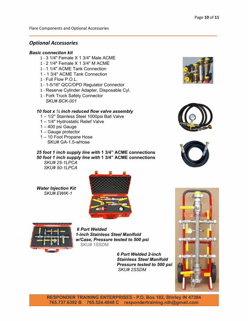
Basic connection kit 1 - 3 1/4" Female X 1 3/4" Male ACME 1 - 2 1/4" Female X 1 3/4" M ACME 1 - 1 1/4" ACME Tank Connection 1 - 1 3/4" ACME Tank Connection 1 - Full Flow P.O.L. 1 - 1-5/16" QCC/OPD Regulator Connector 1 - Reserve Cylinder Adapter, Disposable Cyl. 1 - Fork Truck Safety Connector
SKU# BCK-001 10 foot x ½ inch reduced flow valve assembly
1 – 1/2" Stainless Steel 1000psi Ball Valve 1 – 1/4" Hydrostatic Relief Valve 1 – 400 psi Gauge 1 – Gauge protector 1 – 10 Foot Propane Hose
SKU# GA-1.5-wHose 25 foot 1 inch supply line with 1 3/4” ACME connections 50 foot 1 inch supply line with 1 3/4” ACME connections
SKU# 25-1LPCA SKU# 50-1LPCA
Water Injection Kit
SKU# EWIK-1
6 Port Welded 1-inch Stainless Steel Manifold w/Case, Pressure tested to 500 psi
SKU# 1SSDM
6 Port Welded 2-inch Stainless Steel Manifold Pressure tested to 500 psi SKU# 2SSDM

Page 11 of 11