Embed Size (px)
Citation preview

Translation of the original manual
Assembly and Operating ManualGWB2-finger angular gripper

Imprint
202.00 | GWB | Assembly and Operating Manual | en | 389122
ImprintCopyright:This manual is protected by copyright. The author is SCHUNK GmbH & Co. KG. All rightsreserved. Any reproduction, processing, distribution (making available to third parties),translation or other usage - even excerpts - of the manual is especially prohibited andrequires our written approval.
Technical changes:We reserve the right to make alterations for the purpose of technical improvement.
Document number: 389122
Version: 02.00 | 19/08/2019 | en
© SCHUNK GmbH & Co. KGAll rights reserved.
Dear Customer,thank you for trusting our products and our family-owned company, the leadingtechnology supplier of robots and production machines.Our team is always available to answer any questions on this product and other solutions.Ask us questions and challenge us. We will find a solution!Best regards,Your SCHUNK team
SCHUNK GmbH & Co. KGSpann- und GreiftechnikBahnhofstr. 106 – 134D-74348 Lauffen/NeckarTel. +49-7133-103-0Fax [email protected]

Table of Contents
02.00 | GWB | Assembly and Operating Manual | en | 389122
3
Table of Contents1 General.................................................................................................................... 5
1.1 About this manual ................................................................................................ 51.1.1 Presentation of Warning Labels ............................................................... 51.1.2 Applicable documents .............................................................................. 61.1.3 Sizes .......................................................................................................... 61.1.4 Variants..................................................................................................... 6
1.2 Warranty .............................................................................................................. 61.3 Scope of delivery .................................................................................................. 7
1.3.1 Accessory pack.......................................................................................... 71.4 Accessories ........................................................................................................... 8
1.4.1 Sensors ..................................................................................................... 81.4.2 Sealing kit ................................................................................................. 8
2 Basic safety notes ................................................................................................... 92.1 Intended use......................................................................................................... 92.2 Not intended use.................................................................................................. 92.3 Constructional changes ........................................................................................ 92.4 Spare parts ........................................................................................................... 92.5 Gripper fingers ................................................................................................... 102.6 Ambient conditions and operating conditions ................................................... 102.7 Personnel qualification....................................................................................... 112.8 Personal protective equipment.......................................................................... 122.9 Notes on safe operation ..................................................................................... 122.10 Transport ............................................................................................................ 132.11 Malfunctions....................................................................................................... 132.12 Disposal .............................................................................................................. 132.13 Fundamental dangers......................................................................................... 13
2.13.1 Protection during handling and assembly .............................................. 142.13.2 Protection during commissioning and operation ................................... 142.13.3 Protection against dangerous movements............................................. 152.13.4 Protection against electric shock............................................................ 15
2.14 Notes on particular risks..................................................................................... 16
3 Technical Data ....................................................................................................... 183.1 GWB 100 gripping force diagram ....................................................................... 193.2 Max. permissible forces and moments on the claw jaws / max. finger length of the GWB 100.... 19
Table of Contents
402.00 | GWB | Assembly and Operating Manual | en | 389122
4 Assembly ................................................................................................................ 204.1 Connections........................................................................................................ 20
4.1.1 Mechanical connection........................................................................... 204.1.2 Pneumatic connection............................................................................ 23
4.2 Opening angle limitation .................................................................................... 254.3 Mounting the sensor .......................................................................................... 26
4.3.1 Overview of sensors ............................................................................... 264.3.2 Mounting inductive proximity switch IN 40 ........................................... 274.3.3 Mounting inductive proximity switch IN 80 ........................................... 28
4.4 Top jaws.............................................................................................................. 29
5 Troubleshooting ..................................................................................................... 315.1 Module does not move?..................................................................................... 315.2 Module opens or closes abruptly? .................................................................... 315.3 Gripping force is dropping .................................................................................. 315.4 Opening angle not correct? ................................................................................ 325.5 Gripper opens or closes too slowly?................................................................... 32
6 Maintenance .......................................................................................................... 336.1 Notes .................................................................................................................. 336.2 Maintenance and lubrication intervals .............................................................. 336.3 Lubricants/Lubrication points (basic lubrication) .............................................. 336.4 Disassembly and assembly ................................................................................. 34
6.4.1 Disassembling the GWB 34 - 80 module................................................. 346.4.2 Disassembling the GWB 100 module...................................................... 36
6.5 Servicing and assembling the module ............................................................... 386.5.1 Screw tightening torques ....................................................................... 39
6.6 Assembly drawing............................................................................................... 396.6.1 GWB 34 - 80 assembly ............................................................................ 396.6.2 GWB 100 assembly ................................................................................. 40
7 Translation of original declaration of incorporation ................................................ 41
8 Annex to Declaration of Incorporation.................................................................... 42

General
02.00 | GWB | Assembly and Operating Manual | en | 389122
5
1 General1.1 About this manual
This manual contains important information for a safe andappropriate use of the product.This manual is an integral part of the product and must be keptaccessible for the personnel at all times.Before starting work, the personnel must have read andunderstood this operating manual. Prerequisite for safe working isthe observance of all safety instructions in this manual.Illustrations in this manual are provided for basic understandingand may differ from the actual product design.In addition to these instructions, the documents listed underApplicable documents [} 6] are applicable.
1.1.1 Presentation of Warning Labels
To make risks clear, the following signal words and symbols areused for safety notes.
DANGERDanger for persons!Non-observance will inevitably cause irreversible injury or death.
WARNINGDangers for persons!Non-observance can lead to irreversible injury and even death.
CAUTIONDangers for persons!Non-observance can cause minor injuries.
CAUTIONMaterial damage!Information about avoiding material damage.
General
602.00 | GWB | Assembly and Operating Manual | en | 389122
1.1.2 Applicable documents
• General terms of business *• Catalog data sheet of the purchased product *• Assembly and operating manuals of the accessories *The documents marked with an asterisk (*) can be downloaded onour homepage schunk.com
1.1.3 Sizes
This operating manual applies to the following sizes:• GWB 34• GWB 44• GWB 54• GWB 64• GWB 80• GWB 100
1.1.4 Variants
This operating manual applies to the following variations:• GWBwithout gripping force maintenance• GWBwith gripping force maintenance"O.D. gripping" (AS)• GWBwith gripping force maintenance"I.D. gripping" (IS)• GWBhigh-temperature (V/HT)
1.2 WarrantyIf the product is used as intended, the warranty is valid for 24months from the ex-works delivery date under the followingconditions:• Observe the specified maintenance and lubrication intervals• Observe the ambient conditions and operating conditionsParts touching the workpiece and wear parts are not included inthe warranty.
General
02.00 | GWB | Assembly and Operating Manual | en | 389122
7
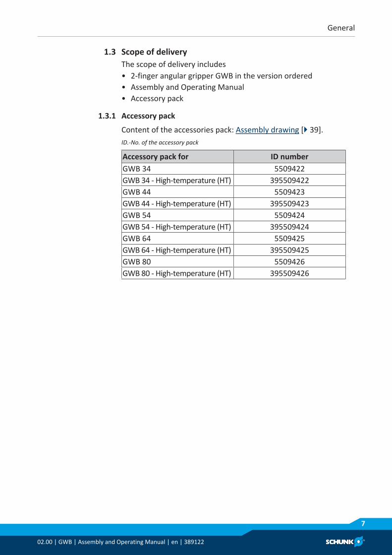
1.3 Scope of deliveryThe scope of delivery includes• 2-finger angular gripper GWB in the version ordered• Assembly and Operating Manual• Accessory pack
1.3.1 Accessory pack
Content of the accessories pack: Assembly drawing [} 39].ID.-No. of the accessory pack
Accessory pack for ID numberGWB 34 5509422GWB 34 - High-temperature (HT) 395509422GWB 44 5509423GWB 44 - High-temperature (HT) 395509423GWB 54 5509424GWB 54 - High-temperature (HT) 395509424GWB 64 5509425GWB 64 - High-temperature (HT) 395509425GWB 80 5509426GWB 80 - High-temperature (HT) 395509426
General
802.00 | GWB | Assembly and Operating Manual | en | 389122
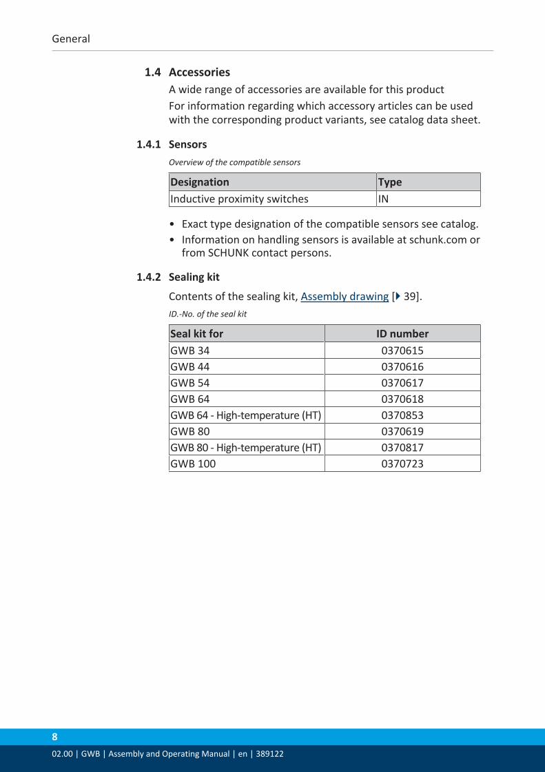
1.4 AccessoriesA wide range of accessories are available for this productFor information regarding which accessory articles can be usedwith the corresponding product variants, see catalog data sheet.
1.4.1 SensorsOverview of the compatible sensors
Designation TypeInductive proximity switches IN
• Exact type designation of the compatible sensors see catalog.• Information on handling sensors is available at schunk.com or
from SCHUNK contact persons.
1.4.2 Sealing kit
Contents of the sealing kit, Assembly drawing [} 39].ID.-No. of the seal kit
Seal kit for ID numberGWB 34 0370615GWB 44 0370616GWB 54 0370617GWB 64 0370618GWB 64 - High-temperature (HT) 0370853GWB 80 0370619GWB 80 - High-temperature (HT) 0370817GWB 100 0370723

Basic safety notes
02.00 | GWB | Assembly and Operating Manual | en | 389122
9
2 Basic safety notes2.1 Intended use
The product is designed exclusively for gripping and temporarilyholding workpieces or objects.• The product may only be used within the scope of its technical
data, Technical Data [} 18].• When implementing and operating components in safety-
related parts of the control systems, the basic safety principlesin accordance with DIN EN ISO 13849-2 apply. The proven safetyprinciples in accordance with DIN EN ISO 13849-2 also apply tocategories 1, 2, 3 and 4.
• The product is intended for installation in a machine/system.The applicable guidelines must be observed and complied with.
• The product is intended for industrial and industry-oriented use.• Appropriate use of the product includes compliance with all
instructions in this manual.
2.2 Not intended useIt is not intended use if the product is used, for example, as apressing tool, stamping tool, lifting gear, guide for tools, cuttingtool, clamping device or a drilling tool.• Any utilization that exceeds or differs from the appropriate use
is regarded as misuse.
2.3 Constructional changesImplementation of structural changesBy conversions, changes, and reworking, e.g. additional threads,holes, or safety devices can impair the functioning or safety of theproduct or damage it.• Structural changes should only be made with the written
approval of SCHUNK.
2.4 Spare partsUse of unauthorized spare partsUsing unauthorized spare parts can endanger personnel anddamage the product or cause it to malfunction.• Use only original spare parts or spares authorized by SCHUNK.
Basic safety notes
1002.00 | GWB | Assembly and Operating Manual | en | 389122
2.5 Gripper fingersRequirements for the gripper fingersStored energy within the product creates the risk of seriousinjuries and significant property damage.• Arrange the gripper fingers in a way that the product reaches
either the position "open" or "closed" in a de-energized state.• Only exchange the gripper fingers when no residual energy
remains in the product.• Make sure that the product and the top jaws are a sufficient
size for the application.
2.6 Ambient conditions and operating conditionsRequired ambient conditions and operating conditionsIncorrect ambient and operating conditions can make the productunsafe, leading to the risk of serious injuries, considerable materialdamage and/or a significant reduction to the product's life span.• Make sure that the product is used only in the context of its
defined application parameters, Technical Data [} 18].• Make sure that the product is a sufficient size for the
application.• Make sure that the environment is free from splash water and
vapors as well as from abrasion or processing dust. Exceptionsare products that are designed especially for contaminatedenvironments.

Basic safety notes
02.00 | GWB | Assembly and Operating Manual | en | 389122
11
2.7 Personnel qualificationInadequate qualifications of the personnelIf the personnel working with the product is not sufficientlyqualified, the result may be serious injuries and significantproperty damage.• All work may only be performed by qualified personnel.• Before working with the product, the personnel must have read
and understood the complete assembly and operating manual.• Observe the national safety regulations and rules and general
safety instructions.The following personal qualifications are necessary for the variousactivities related to the product:
Trained electrician Due to their technical training, knowledge and experience, trainedelectricians are able to work on electrical systems, recognize andavoid possible dangers and know the relevant standards andregulations.
Qualified personnel Due to its technical training, knowledge and experience, qualifiedpersonnel is able to perform the delegated tasks, recognize andavoid possible dangers and knows the relevant standards andregulations.
Instructed person Instructed persons were instructed by the operator about thedelegated tasks and possible dangers due to improper behaviour.
Service personnel ofthe manufacturer
Due to its technical training, knowledge and experience, servicepersonnel of the manufacturer is able to perform the delegatedtasks and to recognize and avoid possible dangers.
Basic safety notes
1202.00 | GWB | Assembly and Operating Manual | en | 389122
2.8 Personal protective equipmentUse of personal protective equipmentPersonal protective equipment serves to protect staff againstdanger which may interfere with their health or safety at work.• When working on and with the product, observe the
occupational health and safety regulations and wear therequired personal protective equipment.
• Observe the valid safety and accident prevention regulations.• Wear protective gloves to guard against sharp edges and
corners or rough surfaces.• Wear heat-resistant protective gloves when handling hot
surfaces.• Wear protective gloves and safety goggles when handling
hazardous substances.• Wear close-fitting protective clothing and also wear long hair in
a hairnet when dealing with moving components.
2.9 Notes on safe operationIncorrect handling of the personnelIncorrect handling and assembly may impair the product's safetyand cause serious injuries and considerable material damage.• Avoid any manner of working that may interfere with the
function and operational safety of the product.• Use the product as intended.• Observe the safety notes and assembly instructions.• Do not expose the product to any corrosive media. This does
not apply to products that are designed for specialenvironments.
• Eliminate any malfunction immediately.• Observe the care and maintenance instructions.• Observe the current safety, accident prevention and
environmental protection regulations regarding the product'sapplication field.

Basic safety notes
02.00 | GWB | Assembly and Operating Manual | en | 389122
13
2.10 TransportHandling during transportIncorrect handling during transport may impair the product'ssafety and cause serious injuries and considerable materialdamage.• When handling heavy weights, use lifting equipment to lift the
product and transport it by appropriate means.• Secure the product against falling during transportation and
handling.• Stand clear of suspended loads.
2.11 MalfunctionsBehavior in case of malfunctions• Immediately remove the product from operation and report the
malfunction to the responsible departments/persons.• Order appropriately trained personnel to rectify the
malfunction.• Do not recommission the product until the malfunction has
been rectified.• Test the product after a malfunction to establish whether it still
functions properly and no increased risks have arisen.
2.12 DisposalHandling of disposalThe incorrect handling of disposal may impair the product's safetyand cause serious injuries as well as considerable material andenvironmental harm.• Follow local regulations on dispatching product components for
recycling or proper disposal.
2.13 Fundamental dangersGeneral• Observe safety distances.• Never deactivate safety devices.• Before commissioning the product, take appropriate protective
measures to secure the danger zone.• Disconnect power sources before installation, modification,
maintenance, or calibration. Ensure that no residual energyremains in the system.
• If the energy supply is connected, do not move any parts byhand.
• Do not reach into the open mechanism or movement area ofthe product during operation.
Basic safety notes
1402.00 | GWB | Assembly and Operating Manual | en | 389122
2.13.1 Protection during handling and assembly
Incorrect handling and assemblyIncorrect handling and assembly may impair the product's safetyand cause serious injuries and considerable material damage.• Have all work carried out by appropriately qualified personnel.• For all work, secure the product against accidental operation.• Observe the relevant accident prevention rules.• Use suitable assembly and transport equipment and take
precautions to prevent jamming and crushing.Incorrect lifting of loadsFalling loads may cause serious injuries and even death.• Stand clear of suspended loads and do not step into their
swiveling range.• Never move loads without supervision.• Do not leave suspended loads unattended.
2.13.2 Protection during commissioning and operation
Falling or violently ejected componentsFalling and violently ejected components can cause serious injuriesand even death.• Take appropriate protective measures to secure the danger
zone.• Never step into the danger zone during operation.

Basic safety notes
02.00 | GWB | Assembly and Operating Manual | en | 389122
15
2.13.3 Protection against dangerous movements
Unexpected movementsResidual energy in the system may cause serious injuries whileworking with the product.• Switch off the energy supply, ensure that no residual energy
remains and secure against inadvertent reactivation.• Never rely solely on the response of the monitoring function to
avert danger. Until the installed monitors become effective, itmust be assumed that the drive movement is faulty, with itsaction being dependent on the control unit and the currentoperating condition of the drive. Perform maintenance work,modifications, and attachments outside the danger zonedefined by the movement range.
• To avoid accidents and/or material damage, human access tothe movement range of the machine must be restricted. Limit/prevent accidental access for people in this area due throughtechnical safety measures. The protective cover and protectivefence must be rigid enough to withstand the maximum possiblemovement energy. EMERGENCY STOP switches must be easilyand quickly accessible. Before starting up the machine orautomated system, check that the EMERGENCY STOP system isworking. Prevent operation of the machine if this protectiveequipment does not function correctly.
2.13.4 Protection against electric shock
Possible electrostatic energyComponents or assembly groups may become electrostaticallycharged. When the electrostatic charge is touched, the dischargemay trigger a shock reaction leading to injuries.• The operator must ensure that all components and assembly
groups are included in the local potential equalisation inaccordance with the applicable regulations.
• While paying attention to the actual conditions of the workingenvironment, the potential equalisation must be implementedby a specialist electrician according to the applicableregulations.
• The effectiveness of the potential equalisation must be verifiedby executing regular safety measurements.

Basic safety notes
1602.00 | GWB | Assembly and Operating Manual | en | 389122
2.14 Notes on particular risks
DANGERRisk of fatal injury from suspended loads!Falling loads can cause serious injuries and even death.• Stand clear of suspended loads and do not step within their
swiveling range.• Never move loads without supervision.• Do not leave suspended loads unattended.• Wear suitable protective equipment.
WARNINGRisk of injury from objects falling and being ejected!Falling and ejected objects during operation can lead to seriousinjury or death.• Take appropriate protective measures to secure the danger
zone.
WARNINGRisk of injury due to unexpected movements!If the power supply is switched on or residual energy remains inthe system, components can move unexpectedly and causeserious injuries.• Before starting any work on the product: Switch off the power
supply and secure against restarting.• Make sure, that no residual energy remains in the system.
WARNINGRisk of injury from crushing and impacts!Serious injury could occur during the base jaw procedure andwhen breaking or loosening the gripper fingers.• Wear suitable protective equipment.• Do not reach into the open mechanism or the movement area
of the product.
WARNINGRisk of injury from sharp edges and corners!Sharp edges and corners can cause cuts.• Use suitable protective equipment.

Basic safety notes
02.00 | GWB | Assembly and Operating Manual | en | 389122
17
WARNINGRisk of injury due to spring forces!Parts are under spring tension on products which clamp usingspring force or which have gripping force maintenance. Whiledisassembling components can move unexpectedly and causeserious injuries.• Disassemble the product cautiously.• Make sure that no residual energy remains in the system.
WARNINGRisk of injury from objects falling during energy supply failureProducts with a mechanical gripping force maintenance can,during energy supply failure, still move independently in thedirection specified by the mechanical gripping forcemaintenance.• Secure the end positions of the product with SCHUNK SDV-P
pressure maintenance valves.
Technical Data
1802.00 | GWB | Assembly and Operating Manual | en | 389122
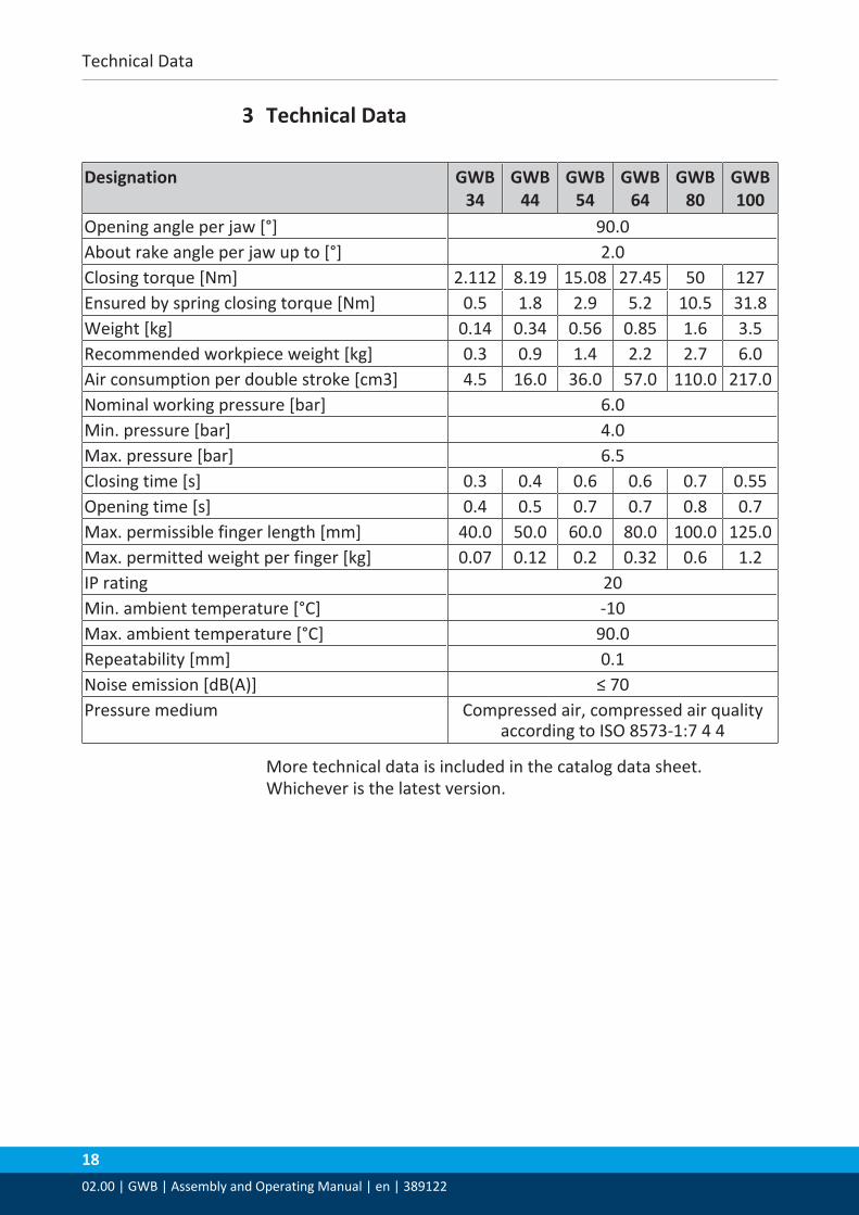
3 Technical Data
Designation GWB34
GWB44
GWB54
GWB64
GWB80
GWB100
Opening angle per jaw [°] 90.0About rake angle per jaw up to [°] 2.0Closing torque [Nm] 2.112 8.19 15.08 27.45 50 127Ensured by spring closing torque [Nm] 0.5 1.8 2.9 5.2 10.5 31.8Weight [kg] 0.14 0.34 0.56 0.85 1.6 3.5Recommended workpiece weight [kg] 0.3 0.9 1.4 2.2 2.7 6.0Air consumption per double stroke [cm3] 4.5 16.0 36.0 57.0 110.0 217.0Nominal working pressure [bar] 6.0Min. pressure [bar] 4.0Max. pressure [bar] 6.5Closing time [s] 0.3 0.4 0.6 0.6 0.7 0.55Opening time [s] 0.4 0.5 0.7 0.7 0.8 0.7Max. permissible finger length [mm] 40.0 50.0 60.0 80.0 100.0 125.0Max. permitted weight per finger [kg] 0.07 0.12 0.2 0.32 0.6 1.2IP rating 20Min. ambient temperature [°C] -10Max. ambient temperature [°C] 90.0Repeatability [mm] 0.1Noise emission [dB(A)] ≤ 70Pressure medium Compressed air, compressed air quality
according to ISO 8573-1:7 4 4
More technical data is included in the catalog data sheet.Whichever is the latest version.
Technical Data
02.00 | GWB | Assembly and Operating Manual | en | 389122
19
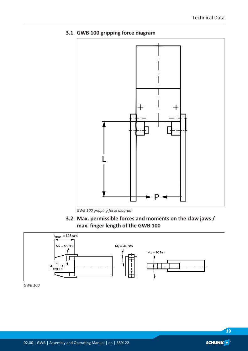
3.1 GWB 100 gripping force diagram
GWB 100 gripping force diagram
3.2 Max. permissible forces and moments on the claw jaws /max. finger length of the GWB 100
GWB 100
Assembly
2002.00 | GWB | Assembly and Operating Manual | en | 389122
4 Assembly4.1 Connections
4.1.1 Mechanical connection
WARNINGRisk of injury when the machine/system moves unexpectedly!Switch off power supply.
Evenness of themounting surface
The values apply to the whole mounting surface to which theproduct is mounted.Requirements for evenness of the mounting surface (Dimensions in mm)
Edge length Permissible unevenness< 100 < 0.02> 100 < 0.05
Assembly
02.00 | GWB | Assembly and Operating Manual | en | 389122
21
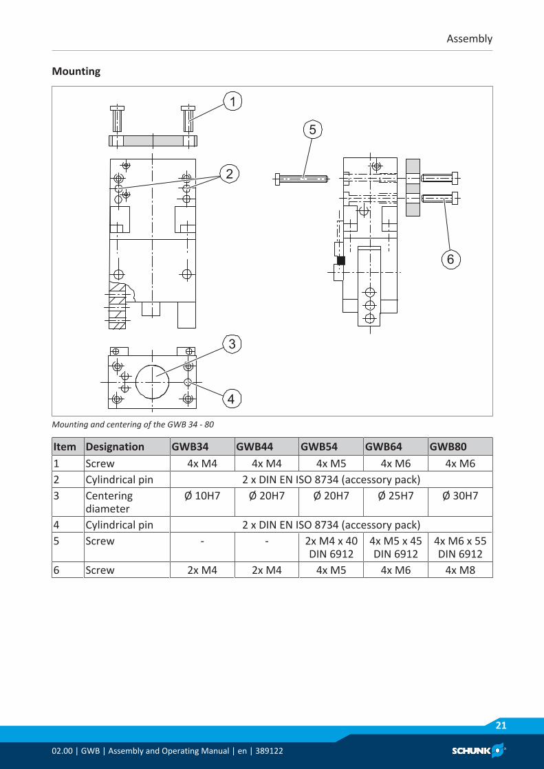
Mounting
Zu /Closed
1
3
4
2
5
6
Mounting and centering of the GWB 34 - 80
Item Designation GWB34 GWB44 GWB54 GWB64 GWB801 Screw 4x M4 4x M4 4x M5 4x M6 4x M62 Cylindrical pin 2 x DIN EN ISO 8734 (accessory pack)3 Centering
diameterØ 10H7 Ø 20H7 Ø 20H7 Ø 25H7 Ø 30H7
4 Cylindrical pin 2 x DIN EN ISO 8734 (accessory pack)5 Screw - - 2x M4 x 40
DIN 69124x M5 x 45DIN 6912
4x M6 x 55DIN 6912
6 Screw 2x M4 2x M4 4x M5 4x M6 4x M8
Assembly
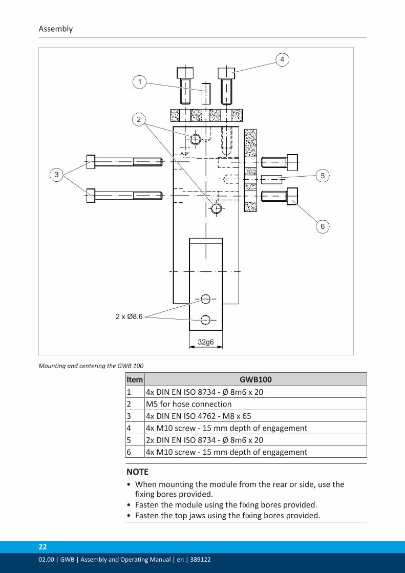
2202.00 | GWB | Assembly and Operating Manual | en | 389122
2 x Ø8.6
32g6
3
4
1
2
5
6
Mounting and centering the GWB 100
Item GWB1001 4x DIN EN ISO 8734 - Ø 8m6 x 202 M5 for hose connection3 4x DIN EN ISO 4762 - M8 x 654 4x M10 screw - 15 mm depth of engagement5 2x DIN EN ISO 8734 - Ø 8m6 x 206 4x M10 screw - 15 mm depth of engagement
NOTE• When mounting the module from the rear or side, use the
fixing bores provided.• Fasten the module using the fixing bores provided.• Fasten the top jaws using the fixing bores provided.
Assembly
02.00 | GWB | Assembly and Operating Manual | en | 389122
23
4.1.2 Pneumatic connection
CAUTIONDamage to the gripper is possible!If the maximum permissible finger weight or the permissiblemass moment of inertia of the fingers is exceeded, the grippercan be damaged.• A jaw movement always has to be without jerks and bounce.• You must therefore implement sufficient reduction and/or
damping.• Observe the diagrams and information in the catalog data
sheet.
NOTE• Observe the requirements for the compressed air supply,
Technical Data [} 18].• In case of compressed air loss (cutting off the energy line), the
components lose their dynamic effects and do not remain in asecure position. However, the use of a SDV-P pressuremaintenance valve is recommended in this case in order tomaintain the dynamic effect for some time. Product variantsare also offered with mechanical gripping force via springs,which also ensure a minimum clamping force in the event of apressure drop.
• Hose-free direct connection: Optionally to ground or to front.• Remove the M3 set-screws (21) from the selected direct
connections and close the lateral hose connections with the M5locking screws supplied.
• Use the O-rings Ø 3 x 1.5 supplied in the accessory kit.• Integrate the one-way flow control valves at a suitable place in
the gripper's pressure supply. Observe the circuit diagram in theprocess (exhaust throttling).
CAUTIONAdjust the speed of the gripper using the one-way flow controlvalves to allow the gripper to open and close smoothly withoutjerking.
Assembly
2402.00 | GWB | Assembly and Operating Manual | en | 389122
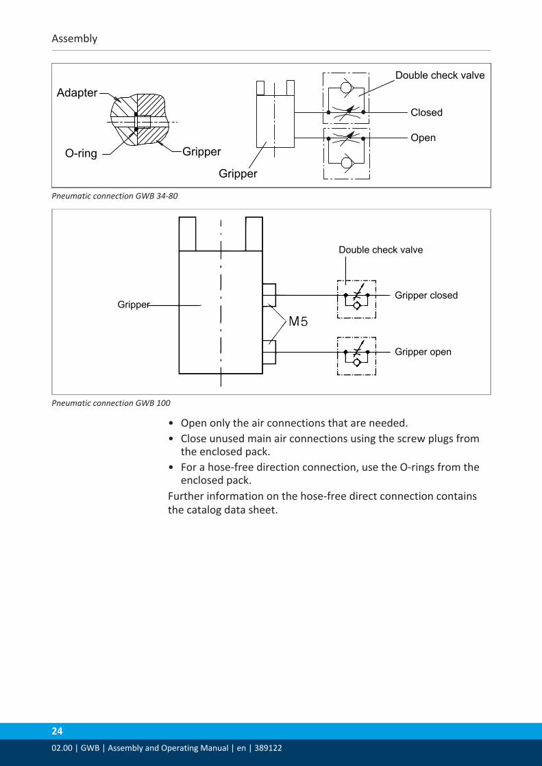
Double check valve
Closed
Open
Adapter
O-ring Gripper
Gripper
Pneumatic connection GWB 34-80
Gripper
Gripper open
Gripper closed
Double check valve
Pneumatic connection GWB 100
• Open only the air connections that are needed.• Close unused main air connections using the screw plugs from
the enclosed pack.• For a hose-free direction connection, use the O-rings from the
enclosed pack.Further information on the hose-free direct connection containsthe catalog data sheet.
Assembly
02.00 | GWB | Assembly and Operating Manual | en | 389122
25
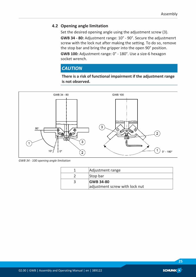
4.2 Opening angle limitationSet the desired opening angle using the adjustment screw (3).GWB 34 - 80: Adjustment range: 10° - 90°. Secure the adjustmenrtscrew with the lock nut after making the setting. To do so, removethe stop bar and bring the gripper into the open 90° position.GWB 100: Adjustment range: 0° - 180°. Use a size-6 hexagonsocket wrench.
CAUTIONThere is a risk of functional impairment if the adjustment rangeis not observed.
GWB 34 - 100 opening angle limitation
1 Adjustment range2 Stop bar3 GWB 34-80
adjustment screw with lock nut
Assembly
2602.00 | GWB | Assembly and Operating Manual | en | 389122
4.3 Mounting the sensor
NOTEObserve the assembly and operating manual of the sensor formounting and connecting.
The product is prepared for the use of sensors.• For the exact type designations of suitable sensors, please see
catalog datasheet and Overview of sensors [} 26].• For technical data for the suitable sensors, see assembly and
operating manual and catalog datasheet.– The assembly and operating manual and catalog datasheet
are included in the scope of delivery for the sensors and areavailable at schunk.com.
• Information on handling sensors is available at schunk.com orfrom SCHUNK contact persons.
4.3.1 Overview of sensors
Designation GWB34 44 54 64 80 100
Inductive proximityswitch IN 40
X X X X X -
Inductive proximityswitch IN 80
X X X X X X
Assembly
02.00 | GWB | Assembly and Operating Manual | en | 389122
27
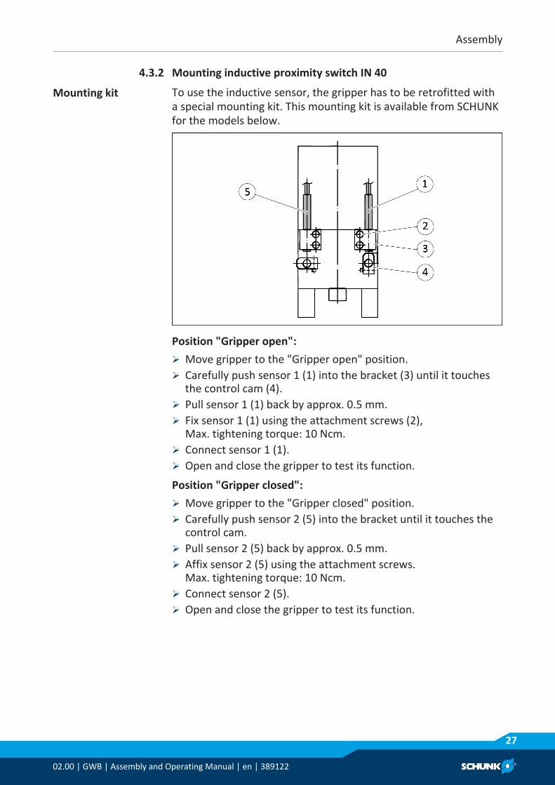
4.3.2 Mounting inductive proximity switch IN 40
Mounting kit To use the inductive sensor, the gripper has to be retrofitted witha special mounting kit. This mounting kit is available from SCHUNKfor the models below.
Position "Gripper open":Ø Move gripper to the "Gripper open" position.Ø Carefully push sensor 1 (1) into the bracket (3) until it touches
the control cam (4).Ø Pull sensor 1 (1) back by approx. 0.5 mm.Ø Fix sensor 1 (1) using the attachment screws (2),
Max. tightening torque: 10 Ncm.Ø Connect sensor 1 (1).Ø Open and close the gripper to test its function.
Position "Gripper closed":Ø Move gripper to the "Gripper closed" position.Ø Carefully push sensor 2 (5) into the bracket until it touches the
control cam.Ø Pull sensor 2 (5) back by approx. 0.5 mm.Ø Affix sensor 2 (5) using the attachment screws.
Max. tightening torque: 10 Ncm.Ø Connect sensor 2 (5).Ø Open and close the gripper to test its function.
Assembly
2802.00 | GWB | Assembly and Operating Manual | en | 389122
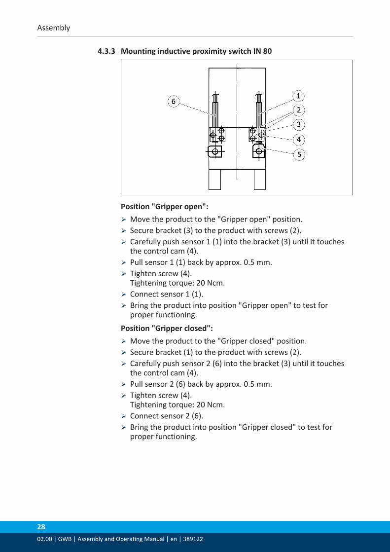
4.3.3 Mounting inductive proximity switch IN 80
Position "Gripper open":Ø Move the product to the "Gripper open" position.Ø Secure bracket (3) to the product with screws (2).Ø Carefully push sensor 1 (1) into the bracket (3) until it touches
the control cam (4).Ø Pull sensor 1 (1) back by approx. 0.5 mm.Ø Tighten screw (4).
Tightening torque: 20 Ncm.Ø Connect sensor 1 (1).Ø Bring the product into position "Gripper open" to test for
proper functioning.
Position "Gripper closed":Ø Move the product to the "Gripper closed" position.Ø Secure bracket (1) to the product with screws (2).Ø Carefully push sensor 2 (6) into the bracket (3) until it touches
the control cam (4).Ø Pull sensor 2 (6) back by approx. 0.5 mm.Ø Tighten screw (4).
Tightening torque: 20 Ncm.Ø Connect sensor 2 (6).Ø Bring the product into position "Gripper closed" to test for
proper functioning.
Assembly
02.00 | GWB | Assembly and Operating Manual | en | 389122
29
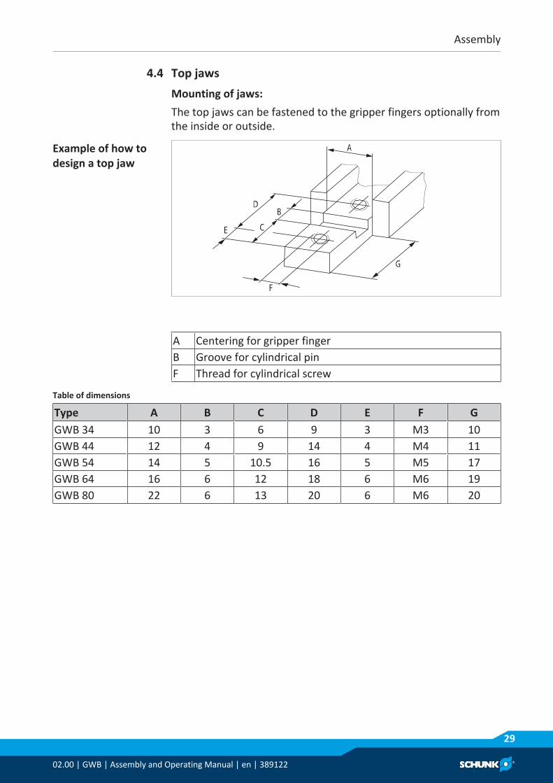
4.4 Top jawsMounting of jaws:The top jaws can be fastened to the gripper fingers optionally fromthe inside or outside.
Example of how todesign a top jaw
A Centering for gripper fingerB Groove for cylindrical pinF Thread for cylindrical screw
Table of dimensions
Type A B C D E F GGWB 34 10 3 6 9 3 M3 10GWB 44 12 4 9 14 4 M4 11GWB 54 14 5 10.5 16 5 M5 17GWB 64 16 6 12 18 6 M6 19GWB 80 22 6 13 20 6 M6 20
Assembly
3002.00 | GWB | Assembly and Operating Manual | en | 389122
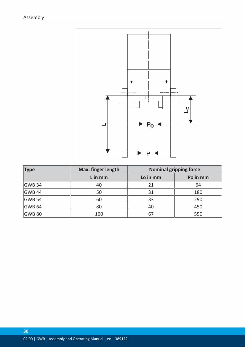
Type Max. finger length Nominal gripping forceL in mm Lo in mm Po in mm
GWB 34 40 21 64GWB 44 50 31 180GWB 54 60 33 290GWB 64 80 40 450GWB 80 100 67 550
Troubleshooting
02.00 | GWB | Assembly and Operating Manual | en | 389122
31
5 Troubleshooting5.1 Module does not move?
Possible cause Corrective actionBase jaws jam in housing, e.g. mountingsurface is not sufficiently even.
Check the evenness of the mounting surface.Mechanical connection [} 20]Loosen the mounting screws of the productand actuate the product again.
Pressure drops below minimum. Check air supply.Pneumatic connection [} 23]Compressed air lines switched. Check compressed air lines.Proximity switch defective or set incorrect. Readjust or change sensor.Unused air connections open. Close unused air connections.Flow control valve closed. Open the flow control valve.Component part defective. Replace component or send it to SCHUNK
for repair.The aperture angle is limited to 0°. Check opening angle limitation.
5.2 Module opens or closes abruptly?Possible cause Corrective actionOne-way flow control valve is missing oradjustet incorrectly.
Install and adjust one-way flow controlvalve.
Loading too large. Check permissible weight and length of thegripper fingers.Mechanical connection [} 20]
5.3 Gripping force is droppingPossible cause Corrective actionCompressed air can escape. Check seals, if necessary, disassemble the
product and replace seals.Too much grease in the mechanicalmovement space.
Clean and lubricate product.
Pressure drops below minimum. Check air supply.Pneumatic connection [} 23]
Component part defective. Replace component or send it to SCHUNKfor repair.
Troubleshooting
3202.00 | GWB | Assembly and Operating Manual | en | 389122
5.4 Opening angle not correct?Possible cause Corrective actionThe aperture angle is limited to 0°. Check opening angle limitation.Pressure drops below minimum. Check air supply.
Pneumatic connection [} 23]
5.5 Gripper opens or closes too slowly?Possible cause Corrective actionOne-way flow control valve is missing oradjustet incorrectly.
Install and adjust one-way flow controlvalve. Pneumatic connection [} 23]
Maintenance
02.00 | GWB | Assembly and Operating Manual | en | 389122
33
6 Maintenance6.1 Notes
Original spare partsUse only original spare parts of SCHUNK when replacing spare andwear parts.
6.2 Maintenance and lubrication intervals
CAUTIONMaterial damage due to hardening lubricants!Lubricants harden more quickly at temperatures above 60°C,leading to possible product damage.• Reduce the lubricant intervals accordingly.
Maintenance- and lubrication interval
Size GWB 34 - 100Interval [Mio. cycles] 2
6.3 Lubricants/Lubrication points (basic lubrication)SCHUNK recommends the lubricants listed.During maintenance, treat all greased areas with lubricant. Thinlyapply lubricant with a lint-free cloth.
Lubricant point LubricantMetallic sliding surfaces Molykote BR 2 plusAll seals Renolit HLT 2Bore hole at the piston Renolit HLT 2

Maintenance
3402.00 | GWB | Assembly and Operating Manual | en | 389122
6.4 Disassembly and assembly
6.4.1 Disassembling the GWB 34 - 80 module
Position of the item numbers Assembly drawing [} 39]
WARNINGRisk of injury due to unexpected movements!If the power supply is switched on or residual energy remains inthe system, components can move unexpectedly and causeserious injuries.• Before starting any work on the product: Switch off the power
supply and secure against restarting.• Make sure, that no residual energy remains in the system.
Ø Remove the compressed air line.Ø Screw the upper part (2) and lower part (1) apart with the four
screws (16).
WARNINGIn the event of a defect, the parts may be under spring tension.Clamp the gripper between "a" and "b" before screwing itapart. Then unclamp it carefully.
Ø Carefully remove the screw (18) and the underlying sealing disk (24).

Maintenance
02.00 | GWB | Assembly and Operating Manual | en | 389122
35
WARNINGThe parts are under spring tension. Clamp the parts between"b" and "c" before taking them apart. Then unclamp themcarefully!
Ø Remove the cylinder piston (6) and the springs (31).Ø Pull out the guide bushing (4).Ø Unscrew the set-screws (20) from the gripper fingers (3). To do
so, insert an Allen key through the assembly bores in the coverhousing (2). The gripper fingers must be in "closed" position forthis purpose.
Ø Mark the installation position of the gripper fingers (3), slideblocks (7) and piston rod (5).
Ø Push the axes (13) out of the cover housing (2).Ø Take the entire lever mechanism (gripper fingers and piston rod
with slide blocks) out of the cover housing.
Maintenance
3602.00 | GWB | Assembly and Operating Manual | en | 389122
6.4.2 Disassembling the GWB 100 module
Position of the item numbers Assembly drawing [} 39]
WARNINGRisk of injury due to unexpected movements!If the power supply is switched on or residual energy remains inthe system, components can move unexpectedly and causeserious injuries.• Before starting any work on the product: Switch off the power
supply and secure against restarting.• Make sure, that no residual energy remains in the system.
WARNINGRisk of injury due to spring forces!The cover is under spring tension.• Carefully disassemble the product.
Ø Remove the bar (9) with the screws (29).Ø Place a workpiece with a length of 64 mm between the fingers (3).Ø Remove the compressed air lines.

Maintenance
02.00 | GWB | Assembly and Operating Manual | en | 389122
37
WARNINGIn the event of a defect, the safety ring (25) and the cover (2)may be under spring tension (F = 500 N). Clamp the gripperbetween position "a" and "b" in a vice in such a manner thatthe cover (2) is also clamped prior to the disassembly. Loosenthe safety ring (25) and then unclamp it carefully.
Ø Carefully remove the safety ring (25) with suitable pliers forsafety rings.
Ø Remove the cover (2).
WARNINGThe parts are under spring tension!(F = 500 N).
Ø Carefully loosen the screw (28) 35 mm. Clamp the gripperbetween the cylinder piston (6) and top edge of the housing.Loosen the screw (28) completely and then carefully unclampthe gripper.
Ø Remove the cylinder piston (6), springs (31) and ring (14).Ø Unscrew the set-screws (32) from the gripper fingers (3).Ø Push the axes (8) out of the housing (1) and mark the
installation position.Ø Remove the entire lever mechanism and mark the installation
position of the gripper fingers (3), bolts (7) and piston rod (5).

Maintenance
3802.00 | GWB | Assembly and Operating Manual | en | 389122
6.5 Servicing and assembling the modulePosition of the item numbers Assembly drawing [} 39]
WARNINGRisk of injury due to spring forces!The cover is under spring tension.• Carefully disassemble the product.
Maintenance • Clean all parts thoroughly and check for damage and wear.• Treat all greased areas with lubricant. Lubricants/Lubrication
points (basic lubrication) [} 33]• Oil or grease bare external steel parts.• Replace all wear parts / seals.
– Position of the wearing parts Assembly drawing [} 39]– Seal kit Sealing kit [} 8]
Assembly Assembly takes place in the opposite order to disassembly.Observe the following:GWB 34- 80: The flat place on the axis (13) must point in thedirection of the set-screw (20).GWB 100: The flat place on the axis (8) must point in the directionof the set-screw (32).• Unless otherwise specified, secure all screws and nuts with
Loctite no. 243 and tighten with the appropriate tighteningtorque. Screw tightening torques [} 39]
Maintenance
02.00 | GWB | Assembly and Operating Manual | en | 389122
39
6.5.1 Screw tightening torques
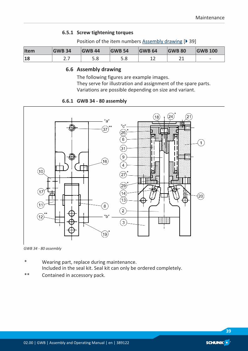
Position of the item numbers Assembly drawing [} 39]
Item GWB 34 GWB 44 GWB 54 GWB 64 GWB 80 GWB 10018 2.7 5.8 5.8 12 21 -
6.6 Assembly drawingThe following figures are example images. They serve for illustration and assignment of the spare parts.Variations are possible depending on size and variant.
6.6.1 GWB 34 - 80 assembly
GWB 34 - 80 assembly
* Wearing part, replace during maintenance.Included in the seal kit. Seal kit can only be ordered completely.
** Contained in accessory pack.
Maintenance
4002.00 | GWB | Assembly and Operating Manual | en | 389122
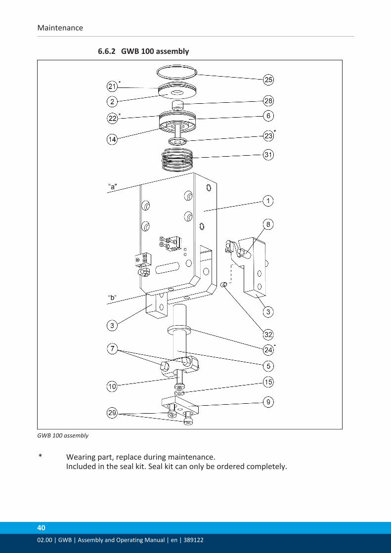
6.6.2 GWB 100 assembly
GWB 100 assembly
* Wearing part, replace during maintenance.Included in the seal kit. Seal kit can only be ordered completely.

Translation of original declaration of incorporation
02.00 | GWB | Assembly and Operating Manual | en | 389122
41
7 Translation of original declaration of incorporationin terms of the Directive 2006/42/EG, Annex II, Part 1.B of the European Parliament and ofthe Council on machinery.
Manufacturer/Distributor
SCHUNK GmbH & Co. KG Spann- und Greiftechnik Bahnhofstr. 106 – 134 D-74348 Lauffen/Neckar
We hereby declare that on the date of the declaration the following partly completedmachine complied with all basic safety and health regulations found in the directive2006/42/EC of the European Parliament and of the Council on machinery. The declarationis rendered invalid if modifications are made to the product.
Product designation: 2-finger angular gripper / GWB / pneumaticID number 0307125 ... 0307140
The partly completed machine may not be put into operation until conformity of themachine into which the partly completed machine is to be installed with the provisions ofthe Machinery Directive (2006/42/EC) is confirmed.
Applied harmonized standards, especially:
EN ISO 12100:2010 Safety of machinery - General principles for design -Risk assessment and risk reduction
The manufacturer agrees to forward on demand the relevant technical documentation forthe partly completed machinery in electronic form to national authorities.The relevant technical documentation according to Annex VII, Part B, belonging to thepartly completed machinery, has been created.
Person authorized to compile the technical documentation: Robert Leuthner, Address: see manufacturer's address
Lauffen/Neckar, August 2019 p.p. Ralf Winkler, Manager for development
of gripping system components
Annex to Declaration of Incorporation
4202.00 | GWB | Assembly and Operating Manual | en | 389122
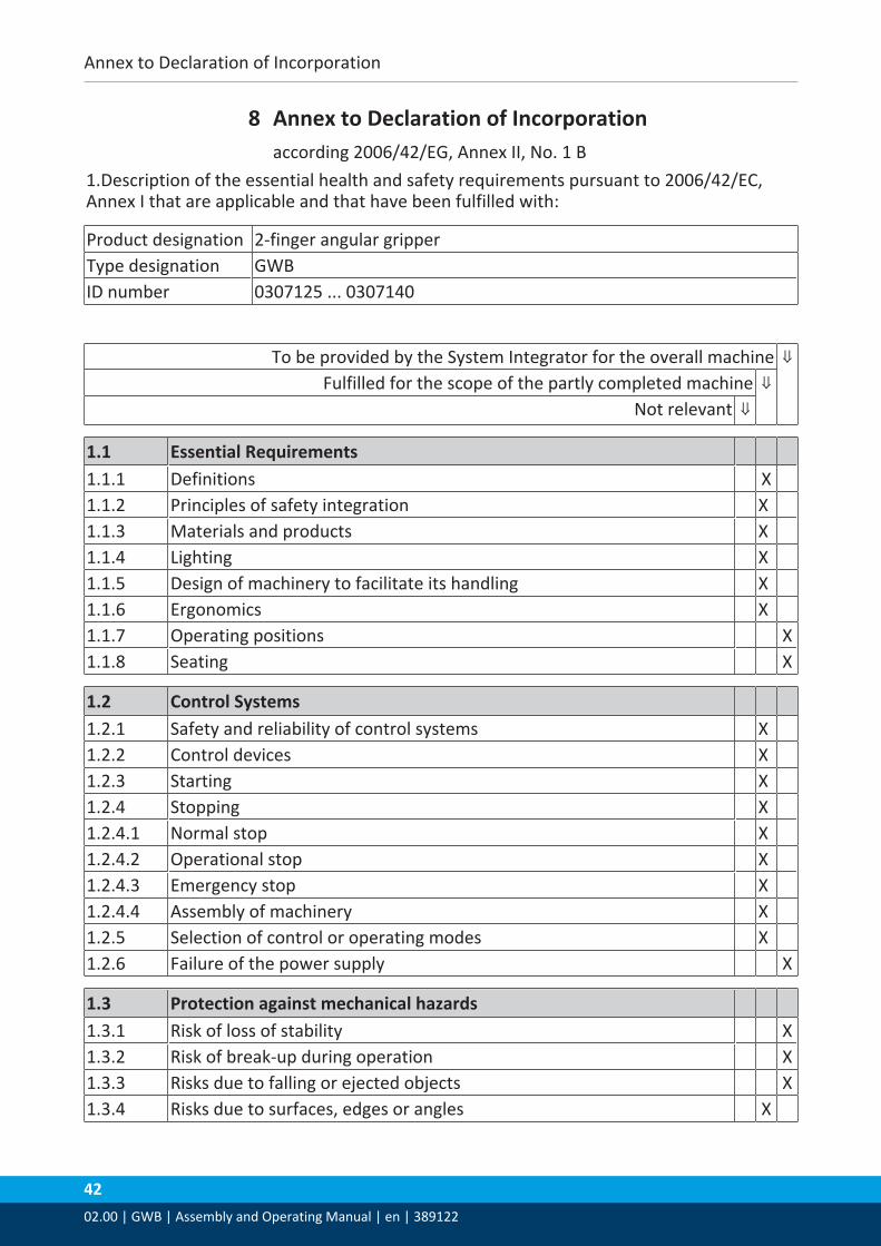
8 Annex to Declaration of Incorporationaccording 2006/42/EG, Annex II, No. 1 B
1.Description of the essential health and safety requirements pursuant to 2006/42/EC,Annex I that are applicable and that have been fulfilled with:
Product designation 2-finger angular gripperType designation GWBID number 0307125 ... 0307140
To be provided by the System Integrator for the overall machine ⇓Fulfilled for the scope of the partly completed machine ⇓
Not relevant ⇓
1.1 Essential Requirements1.1.1 Definitions X1.1.2 Principles of safety integration X1.1.3 Materials and products X1.1.4 Lighting X1.1.5 Design of machinery to facilitate its handling X1.1.6 Ergonomics X1.1.7 Operating positions X1.1.8 Seating X
1.2 Control Systems1.2.1 Safety and reliability of control systems X1.2.2 Control devices X1.2.3 Starting X1.2.4 Stopping X1.2.4.1 Normal stop X1.2.4.2 Operational stop X1.2.4.3 Emergency stop X1.2.4.4 Assembly of machinery X1.2.5 Selection of control or operating modes X1.2.6 Failure of the power supply X
1.3 Protection against mechanical hazards1.3.1 Risk of loss of stability X1.3.2 Risk of break-up during operation X1.3.3 Risks due to falling or ejected objects X1.3.4 Risks due to surfaces, edges or angles X

Annex to Declaration of Incorporation
02.00 | GWB | Assembly and Operating Manual | en | 389122
43
1.3 Protection against mechanical hazards1.3.5 Risks related to combined machinery X1.3.6 Risks related to variations in operating conditions X1.3.7 Risks related to moving parts X1.3.8 Choice of protection against risks arising from moving parts X1.3.8.1 Moving transmission parts X1.3.8.2 Moving parts involved in the process X1.3.9 Risks of uncontrolled movements X
1.4 Required characteristics of guards and protective devices1.4.1 General requirements X1.4.2 Special requirements for guards X1.4.2.1 Fixed guards X1.4.2.2 Interlocking movable guards X1.4.2.3 Adjustable guards restricting access X1.4.3 Special requirements for protective devices X
1.5 Risks due to other hazards1.5.1 Electricity supply X1.5.2 Static electricity X1.5.3 Energy supply other than electricity X1.5.4 Errors of fitting X1.5.5 Extreme temperatures X1.5.6 Fire X1.5.7 Explosion X1.5.8 Noise X1.5.9 Vibrations X1.5.10 Radiation X1.5.11 External radiation X1.5.12 Laser radiation X1.5.13 Emissions of hazardous materials and substances X1.5.14 Risk of being trapped in a machine X1.5.15 Risk of slipping, tripping or falling X1.5.16 Lightning X
1.6 Maintenance1.6.1 Machinery maintenance X1.6.2 Access to operating positions and servicing points X1.6.3 Isolation of energy sources X1.6.4 Operator intervention X1.6.5 Cleaning of internal parts X

Annex to Declaration of Incorporation
4402.00 | GWB | Assembly and Operating Manual | en | 389122
1.7 Information1.7.1 Information and warnings on the machinery X1.7.1.1 Information and information devices X1.7.1.2 Warning devices X1.7.2 Warning of residual risks X1.7.3 Marking of machinery X1.7.4 Instructions X1.7.4.1 General principles for the drafting of instructions X1.7.4.2 Contents of the instructions X1.7.4.3 Sales literature X
The classification from Annex 1 is to be supplemented from hereforward.
2 Supplementary essential health and safety requirements for certaincategories of machinery
X
2.1 Foodstuffs machinery and machinery for cosmetics or pharmaceuticalproducts
X
2.2 Portable hand-held and/or guided machinery X2.2.1 Portable fixing and other impact machinery X2.3 Machinery for working wood and material with similar physical
characteristicsX
3 Supplementary essential health and safety requirements to offsethazards due to the mobility of machinery
X
4 Supplementary essential health and safety requirements to offsethazards due to lifting operations
X
5 Supplementary essential health and safety requirements for machineryintended for underground work
X
6 Supplementary essential health and safety requirements for machinerypresenting particular hazards due to the lifting of persons
X