Embed Size (px)
Citation preview

Gain Enhancement of An Ultra Wide Band
Rectangular Antenna
Cengizhan Mustafa Dikmen
Kocaeli University
Köseköy Vocational School
Kocaeli, Turkey
Gonca Çakır
Kocaeli University
Electronics and Communication Engineering
Kocaeli, Turkey
Abstract—In this study, an ultra wide band simple
geometry rectangular antenna which radiates at 3-12 GHz is
designed and the gain of the antenna is enhanced step by step
without using any additional structure to prevent enlargement
the size of the antenna. The proposed antenna has a size of
80mm width and 38 mm length. The gain of the antenna is
enhanced at whole radiation bandwith. The gain increment is
minimum 1.5 dB and maximum 4 dB which depends on
radiation frequency. The gain of proposed antenna varies from
4 to 7.2 dB. Return loss and enhancement of the gain is
simulated at each stage.
Keywords—rectangular microstrip antenna, gain
enhancement, ultra wide band antenna.
I. INTRODUCTION
As we know Federal Communication Commission (FCC) declared 3.1-10.6 GHz frequency range as UWB (ultra wide band). There have been many UWB antenna studies since the declaration. Some of them are about gain enhancement of microstrip antennas because of low gain characteristic. There are different techniques to increase the gain of them. In some studies, reflective surface is placed at the back side of the antenna. Some of them uses horn antennas and the other uses frequency selective surfaces. The other studies focus on modification of the structure of reference antennas. For example, gain of a vivaldi antenna is enhanced about 1dB [1]. In another study, it’s used a ring slot on path with the filter increases gain [2]. Another study two slots are located on a bow tie antenna to increase the gain [3]. Another technique is to locate an air gap between the dielectric material and the ground plate of the antenna [4]. In another study slots are located on the ground plane to increase the gain of the horse shoe antenna. The gain is increased about 1 dB [5]. Locating two blocks at each side of the antenna increases the gain at both low and high end frequencies [6]. Locating additional blocks on the same antenna affects the gain especially at only high frequencies [7]. Some studies which uses rectangular patch has gain which varies between 1 dB and 5.5 dB [8]. In another study, impedance bandwith is studied and the gain varies from 3 dB to 5.7 dB [9]. Some types of u shape rectangular antenna have a gain range 2.8-6.8 dB [10]. The techniques that used in some studies increase the gain at high end frequencies [5,7,11].
In this study, rectangular shaped antenna is designed to enhance the gain that radiates at 3-12 GHz. The structure of reference antenna is modified step by step to improve gain characteristic. In addition, the changes on the reference antenna is performed without extra structures. It is well known that band gap or locating horn antenna at the back of microstrip antenna or enlargement of the reference antenna increase the gain. But our purpose is just to modify the
reference antenna without enlargement. The other goal of this study is to increase the gain at whole bandwith. The gain of the proposed antenna reached to 4-7.2 dB. As a result, the gain is increased about 1.5-4 dB at the whole radiation frequencies. All the simulations are performed by Computer Simulation Technology Microwave Studio (CST MWS) program.
II. STRUCTURE OF THE ANTENNA AND DESIGNING STAGES
The antenna is designed with a rectangular patch. Thewidth W is 80 mm and the length L is 38 mm (Fig. 1). Rogers RT5800 type dielectric material (εr=2,2) which thickness of h=0.762mm is used.
Fig. 1. Design of the antenna.
The reference antenna has a rectangular geometry patch. The patch is notched and extended asymmetrically to increase the gain. The notch has a size of P4=4 mm and P5=12 mm. The proposed antenna has a u-shape patch geometry. The lengths of the patch which is modified are P1=10.2 mm, P2=7.8 mm, P3=6.8 mm, P6=5.8 mm and P7=4.8 mm. The patch of the antenna is fed by a feed line that length FL is 21.8 mm. The width of the feed line FW is 10 mm. To match impedance of the antenna to 50 ohm, the FG
gap is set to 0.8 mm. A strip line is located S1=2mm awayfrom the edge of the ground line. The height of the strip isS4=4 mm and the width is SW=2 3mm. The ground layersurrounds the edge of the antenna with the line which thewidth is S2=3 mm and E2=2 mm. The length E1 is 26 mm.Two square slot are located to ground layer which is G3=9.2mm and G6=9 mm. The square slot has a dimension of
2018 International Conference on Electrical Engineering and Computer Science (ICEECS)
101

G1=G2=16 mm. The height of the ground layer is G4=19.36mm and G5=20 mm.
Fig. 2. Structural designing steps.
The gain is enhanced at five different stages. At the first stage, a simple rectangular antenna which radiates at UWB frequency range is designed. It’s well known that there is no exact procedure to design an UWB antenna. That’s why, many simulations are performed to obtain UWB radiation. The antenna is fed by a coplanar feed line (Fig. 2a). The reference antenna radiates at 3-12 GHz frequency range (Fig. 3). The gain of the reference antenna varies between 2 and 4 dB at the whole bandwidth (Fig. 4). At the second step the
patch is notched (Fig. 2b). The notch increases the gain about 0.5 dB at 6-10 GHz. Then the patch is extended for 3 mm at the right side and a strip is located at the opposite side (Fig. 3c). At this stage antenna radiates asymmetrically because of the asymmetric structure modification. To make it clear visibility that the gain enhancement of the reference antenna for first three stages is shown at Figure 4. This modification increases the gain 1dB at 4.5 and 5.5 GHz, 2 dB at 9 GHz. At the next stage ground layer is extended as a strip along the edge of the antenna (Fig. 2d). At this stage the current is directed along the strips and the gain is enhanced 0.5-4 dB at the whole bandwith (Fig. 5). At this stage the radiation of the antenna is directed to yz plane at 4-5 GHz. As seen at Figure 6 the directivity of the antenna at 4 and 5.5 GHz has a fork shape and the modification at this stage provide us more directional radiation. Finally, two square slot is inserted at the bottom edge of the ground layer. It provides 0.5-1 dB gain enhancement at 4, 6, 7, 5 and 10 GHz. Figure 7 shows that the final gain comparison of both reference and the proposed antenna. The gain of the proposed antenna is enhanced 1.5 dB at 4 GHz. On the other way, the increment of gain reaches to 4 dB maximum at 5.5 GHz. The gain exceeds 7 dB level at this frequency. Figure 8 shows that the 3D perspective view of directivity for rectangular and proposed antenna. It is clear that the modified antenna is more directive and the gain is increased at every radiation frequency. If we compare the surface current distribution, we see that the current especially concentrated on the structures of the modified parts of the antenna (Fig. 9).
Fig. 3. S11 simulations of antennas at each stage.
Fig. 4. The gain enhancement for the first three designing steps.
(a)
(b)
(c)
(d)
(e)
102
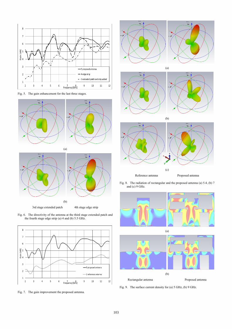
Fig. 5. The gain enhancement for the last three stages.
(a)
(b)
3rd stage extended patch 4th stage edge strip
Fig. 6. The directivity of the antenna at the third stage extended patch and
the fourth stage edge strip (a) 4 and (b) 5.5 GHz.
Fig. 7. The gain improvement the proposed antenna.
(a)
(b)
(c)
Reference antenna Proposed antenna
Fig. 8. The radiation of rectangular and the proposed antenna (a) 5.4, (b) 7
and (c) 9 GHz.
(a)
(b)
Rectangular antenna Proposed antenna
Fig. 9. The surface current density for (a) 5 GHz, (b) 9 GHz.
103

III. CONCLUSION
In this study, gain improvement for an UWB rectangular antenna is performed. The goal of this study is to increase the gain of the reference antenna without enlargement the structural size which is 80x38mm using any additional FSS structure or reflective layer structures. The gain of the rectangular antenna is enhanced step by step and the effects of each stages are analyzed. The modifications that applied to reference antenna increased the gain 1,5-4 dB. The gain of the proposed antenna varies between 4-7.2 dB. The gain is enhanced at whole radiation frequencies without any gain loss. In the future studies these modifications can be applied to any other simple geometries. Additionally, using reflective surface or horn antenna with this design, will be able to provide us much better gain enhancement.
REFERENCES
[1] G. K. Pandey., H. S. Singh, P. K. Bharti, A. Pandey, “High Gain Vivaldi Antenna for Radar and Microwave Imaging Applications”,International Journal of Signal Processing Systems, vol. 3, no. 1,p.35-39, June 2015.
[2] M. C. Tang, T. Shi, and R. W. Ziolkowski, “ Planar UltrawidebandAntennas With Improved Realized Gain Performance”, IEEETransactions on Antennas and Propagation, vol. 64, no. 1, p.61-69, January 2016.
[3] M. Yang, X. Yin, Z. N. Chen, Rong Y., H. Qian, “Planar Image-rejectBow-tie Antenna with Gain Enhancement for SuperheterodyneApplications”, IEEE Antennas and Wireless Propagation Letters, vol.15, p.658-661, 2016.
[4] R. Saha, S. Maity, N. Trigunayat, “ Enhancementof Gain, Bandwidthand Directivity of a Patch Antenna by Increasing Dielectric Layers of
the Substrate through Micromachining Technique for RFID Application”, International Conference on Advances in Computer Engineering and Applications (ICACEA), Ghaziabad, India, p.321-324, 2015.
[5] V. Tiwari, K. Vyas, N. Goyal, “Gain Enhancement of a CPW-FedHorse Shoe Shaped Slot Antenna with Defected Ground Structuresfor WiMax/WLAN Applications”, IEEE International Conference onRecent Advances and Innovations in Engineering, Jaipur, India, p.1-4, May 2014.
[6] Y. Ranga, K. P. Esselle, A. R. Weily, “A simple thin antenna with an enhanced gain for MB-OFDM UWB systems”, 4th International Conference on Signal Processing and Communication Systems(ICSPCS), Gold Coast, Queensland, p.1-4, November 2010.
[7] Y. R. Ranga, S. G. Hay, A. K. Verma, K.P. Esselle, “An UltraWideband Antenna with Proximity-Coupled Multiple Shallow Cavities for Uniform Gain”, International Symposium on Communications and Information Technologies (ISCIT), Jaipur, India, p.1-5, May 2014.
[8] M. A. Hassanien, E. K. I. Hamad, “Compact Rectangular U-shped Slot Microstrip Patch Antenna for UWB Applications”, Middle East Conference on Antennas and Propagatio (MECAP), Cairo, Egypt,October 2010.
[9] A. B. Abde-rahman, A. Z. El Dein, M. A. Mostafa, “Impedance Bandwith Enhancement of UWB Monopole Antenna by Using Rectangular Shaped Slot”, 28th National Radio Science Conference (NRSC 2011), Egypt, April 2011.
[10] M. N. Moghadasi, M. Koohestani, “A Simple Fed Planar Rectangular Slot Monopole Antenna”, Loughborough Antennas & Propogation Conference, Loughborough, UK, p.1-4, November 2011.
[11] J. S. Khinda, M. R. Tripathy, “Wideband Triangular Antenna design with enhanced Gain Bandwidth for Wireless CommunicationApplications”, Proceedings of 2015 RAECS UIET Panjab University Chandigarh, December 2015.
104