Embed Size (px)
Citation preview
NEW SARAIGHAT BRIDGE‐ A VITAL LINK TO GATEWAY OF NORTH EAST
V. N. HeggadeSenior Vice President & Member
Board of Management of Gammon India Limited. Mumbai
93ARKEY CONFERENCE SERVICE CELL, PUNE
Managed by
AbstractThe Brahmaputra River is the major International waterways of the North East. Due to its higher bed slope compared to other major rivers in India, the river has a tendency to roll instead of flowing down as a sheet producing vertical eddies culminating in huge siltation.The new Saraighat bridge is a three-lane bridge across the river to connect Guwahati city with North Guwahati parallel to 1275m long existing Saraighat Rail cum Road Bridge which was inaugurated by then Prime minister Pandit Jawaharlal Nehru. The bridge consists of continuous spans of 105m + 150m + 8x122.948m + 150m + 105m giving the overall length as 1493.584m between Expansion Joints.The bridge superstructure was realised by cast-in-situ balanced cantilever method of construction. The deck section has a 9.0m carriageway with 2.0m wide footpath on one side and anti-crash barrier on both sides of carriageway, with the overall deck-width of 13.875m. The deck is supported on POT-fixed and POT/PTFE-sliding bearings, placed on hollow R.C. piers with semicircular cut and ease waters, the latter resting on double-D caissons. The bridge is located in the highest seismic zone V. A line of two Fixed POT bearings is provided on the central pier and the guided POT/PTFE-sliding bearings are provided on all other supports. Shock Transmission Units (STUs) are provided to distribute the horizontal seismic forces among the supports.
Key words : Caissons, Cofferdams, Cantilever Construction, Seismic Transmission units, Expansion joints.
2 0 1 7
INTRODUCTION
Guwahati's 'urban form' is somewhat like a starfish. With
a core in the central areas, the city has tentacles
extending in the form of growth corridors towards south,
north, east and west. The most important corridor is
along the Guwahati-Shillong (GS) Road towards the
south (almost 15 km from the city-center). The GS Road
is an important commercial area with retail, wholesale
and offices developed along the main road. The city is
having notable changes in its morphology with rapid
expansion.
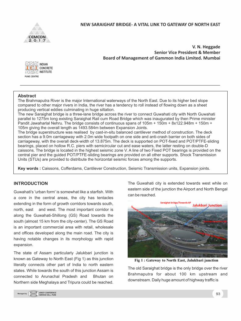
The state of Assam particularly Jalukbari junction is
known as Gateway to North East (Fig 1) as this junction
literally connects other part of India to north eastern
states. While towards the south of this junction Assam is
connected to Arunachal Pradesh and Bhutan on
Northern side Meghalaya and Tripura could be reached.
The Guwahati city is extended towards west while on
eastern side of the junction the Airport and North Bengal
can be reached.
The old Saraighat bridge is the only bridge over the river
Brahmaputra for about 100 km upstream and
downstream. Daily huge amount of highway traffic is

is forced to take Saraighat Bridge in order to enter city
and northeast States, resulting in slow moving long
queues, almost choking the vehicular flow. This traffic
jam on the way to city is responsible for the further
increment in travel time. It takes about 75-90 min to reach
city due to high level of congestion.
The old Saraighat Bridge (Fig 2) was the first rail-cum-
road bridge constructed over the in Brahmaputra River
Guwahati. This bridge is a vital link and connects North
bank of Guwahati city to that of South bank as such has
become a very important urban structure over the period
catering for ever increasing traffic intensity due to
unremitting growth of the city. It was opened to traffic in
April 1962 by then Prime Minister . The Jawaharlal Nehru
Lachit Borphukan Park is situated on the south end and
Chilarai Park situated on the north end of the bridge. The
bridge was built for the North Frontier Railway.
Guwahati is the largest city in Assam and one of the
fastest developing cities in India. With the rapid growth of
population in the city and ever-increasing traffic on old
bridge which connects rest of India North East, the road
traffic problems were also increasing at an alarming rate
resulting in perennial traffic jams on the bridge. To ease
out this problem, NHAI (National Highway Authority Of
India) proposed new Saraighat bridge around 40 metres
south of the existing old Saraighat bridge in the year
2006. The bridge, which will connect the city's south and
north banks, is expected to reduce the pressure of traffic
on old Saraighat bridge, however the same necessitated
later Signal free elevated corridor at Jalukbari junction (
Fig 3 ) as a Gateway North East.
The traffic intersection at Jalukbari touches the
approach of the bridge and the existing roads. The flyover
is 244 metres long and have six lanes. Each three-lane
carriageway has separate foundations, substructure and
superstructure.
Three numbers of loops and ramps each, an underpass
and approach embankment made up of retaining walls
touch the existing roads in all direction providing a signal
free intersection to majority of the North eastern states.
2.0 NEW SARAIGHAT BRIDGE
2.1 General
The Brahmaputra, is the longest river in Asia, having a
multi-channel river system having a high braiding
tendency.
The nature and behaviors of Brahmaputra is quite
different than that of other Indian rivers - its Flow
concentration, unpredictable shifting of main course,
innumerable sand-bars, deflected flow pattern coupled
with high bed scour tendency make difficult for
successful construct ions besides having
inconsiderable suitable construction period .
The flood discharge of Brahmaputra (Fig 4) is 90400
M3/sec (4th in world) with an observed average
velocity of 5.00 m/sec.
reaction in terms of conservatism leading to huge
financial drain on the country's exchequer.
It is one of the largest rivers in Asia with a total length of
about 2900 km, originating from China,out of which a
stretch of about 920 km lies in the northeast region of
Indian Catchment area of about 1.80 lac Sq. Km, keeping
94ARKEY CONFERENCE SERVICE CELL, PUNE
Managed by
a width of 10-16 km. Its annual sediment load is
estimated to be about 397 million ton. Extensive river
training works needed to establish works and it has been
traditionally considered as extremely difficult for bridging
Seasonal Change in the course of River and Water depth
at different locations, result in change in construction
methodology and materials, plant & machineries
movement/ logistics to desired locations.
Early onset of monsoon, prolonged monsoon and
unprecedented flash floods pose constant disruption in
works. The peak working season is practically, reduced
to 4 months only i.e, from 15th Nov. to 15th March.
2.2 Salient features of the bridge
The vital urban transportation link new Saraighat bridge
is a three-lane bridge across the river Brahmaputra to
connect Guwahati city with North Guwahati parallel to
1275m long existing Saraighat Rail cum Road Bridge.
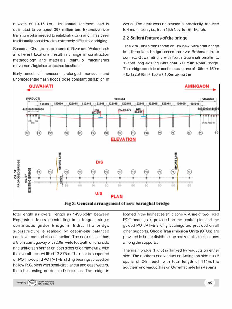
The bridge consists of continuous spans of 105m + 150m
+ 8x122.948m + 150m + 105m giving the
total length as overall length as 1493.584m between
Expansion Joints culminating in a longest single
continuous girder bridge in India. The bridge
superstructure is realised by cast-in-situ balanced
cantilever method of construction. The deck section has
a 9.0m carriageway with 2.0m wide footpath on one side
and anti-crash barrier on both sides of carriageway, with
the overall deck-width of 13.875m. The deck is supported
on POT-fixed and POT/PTFE-sliding bearings, placed on
hollow R.C. piers with semi-circular cut and ease waters,
the latter resting on double-D caissons. The bridge is
located in the highest seismic zone V. A line of two Fixed
POT bearings is provided on the central pier and the
guided POT/PTFE-sliding bearings are provided on all
other supports. Shock Transmission Units (STUs) are
provided to better distribute the horizontal seismic forces
among the supports.
The main bridge (Fig 5) is flanked by viaducts on either
side. The northern end viaduct on Amingaon side has 6
spans of 24m each with total length of 144m.The
southern end viaduct has on Guwahati side has 4 spans
95ARKEY CONFERENCE SERVICE CELL, PUNE
Managed by

of 27m with total length of 108m.
The main bridge superstructure has around 18500 cum
of M50 grade of concrete in combination with 9300 cum of
M60 grade of concrete. While the High Tensile strands
was around 1500 t, the un tensioned steel accounted for
6631 t in superstructure of main bridge. The foundations
and substructure together has around 83600 cum of M35
grade of concrete embedded with 4550 t of reinforcement
steel.
This contract was an item rate contract with the complete
designs made available during tender stage itself.
However, original designer was not available during the
execution after the award of the job for any clarifications
on the designs and drawings. The contract like this where
the final design of the structure is dictated by construction
methodology to be used is well suited for lumpsum
contracting model where designs are done by contractor
himself. As that it may be, during the construction of the
viaduct the structural cracks appeared on the piers. It was
quite apparent that the reinforcement provided in the
piers were inadequate. Therefore the decision was taken
to get the entire design rechecked as such the job was
almost like a design build contract.
While redesigning superstructure of main bridge it was
found that depth of the girder needs to be increased but
as viaducts were completed already, increasing the
height of Girder was not possible. So for a short length
Concrete strength had to be augmented to M60 grade
from M50 grade.
All these designing activities have eaten up sufficient
working times which lead to the delay in completion of the
project. Time cycle for casting of segments by CLC
gantries has been increased due to increase in quantity
of Reinforcement steel & H.T. Strands for Superstructure
while redesigning.
The designed founding level of wells as per the tendered
design was found to be inadequate. The depths of the
revised founding levels were generally increased by 5
metres and in some cases up to 10m even.
3.0 FOUNDATIONS
The main bridge has 11 numbers ( P7 to P17) of pier well
foundations out of which 7 numbers are constructed by
floating steel caissons while rest are constructed by
island method. Generally well foundations are 16m by
10m size double D wells being designed
96ARKEY CONFERENCE SERVICE CELL, PUNE
Managed by

with the top of 3.0m thick well cap at RL 40.0m and
founding levels at RL -11.40m. The design scour is
around the RL 7.684m providing the grip of around
19.0m. However, due to redesigning during construction,
the final founding levels are varying and for some
foundations had to be taken down to the RL-21.10m
making the total depth of double D well foundation to
Existing Saraighat Bridge is just 40m (upstream) away
from new Bridge & under influence zone of foundation of
existing Bridge.Special precaution has been taken while
execution of well foundation works of new Bridge under
high current of water and sand blow which could be
encountered during the sinking of new wells which may
jeopardise the old bridge.
At some locations protruded Reinforcement steel were
cut due to abrasive action of silt content in water coupled
with high water current during the flood.
To sink double D wells of 61m deep & to keep tilts & shifts
within a permissible limit, utmost caution has been taken
by adopting pre-defined methodology of sinking. Well
foundations which were very near to crude oil pipeline at
P7 & P17 locations were completed successfully without
diverting these pipelines. Special structures were to be
designed & constructed for support of these Oil
Pipelines.
Brahmaputra river at this location has an annual mean
discharge of 46,100m3/sec with the maximum recorded
discharge of 72,400m3/sec. On the alluvial soil bed, the
river rolls at the maximum mean velocity of 5m/sec.\
Early Flood / Flash Flood in the river restricts the working
season to a very short period of six months from
November to April. In the Himalayan rivers, the available
working season gets shifted due to flash floods,
unexpected rains etc. imposing challenges for planning
and resource mobilisation. Due to very short working
season available for construction, it demands huge
mobilization & meticulous resource planning for
execution, transportation of concrete & other
construction materials by barge across the river under
heavy water current. The short working season
warranted additional precautions like, sinking of wells up
to safe grip (below scour level), removing obstructions /
dredged materials accumulated near the well for clear
water passage, if plugging of well was not possible at the
end of working season, covering of the at the top etc.
Even in working season, it is very difficult for execution of
deep caisson foundations against heavy water current in
River Brahmaputra because of the narrow passage way
of water at this location. As the bottom of Well cap is at
LWL of RL 40.0m additional coffer dam has been
constructed to retain the water for executing the Well cap.
When well foundations are chosen where the velocity
and depth of the water is low, sand islands or artificial
cofferdams (Fig. 8) are constructed, providing sand bags
to support the sand in the location of pitching of
cuttingedge. The sand island or construction of
cofferdam bund is an ingenuous application, which is in
practice in India for many years. Here, the island is made
to bring the ground level above water level and wells are
constructed on the level surface. The four of the
foundations near the banks were constructed using this
technology.
At the location of the foundations Balli piles ( Fig 8 )were
driven almost to the diameter of 20 m to accommodate
16m X 10m double D well and the Balli piled cofferdam
97ARKEY CONFERENCE SERVICE CELL, PUNE
Managed by

walls were filled with sand bags to retain the sand island
with in. After pitching the cutting edge the curb walls of
4.5m height are installed and the reinforcement inside
are fixed prior to the commencement of concreting. The
material inside is gradually scooped out to facilitate the
sinking under its own weight. As the sinking proceeds, the
steining is built up in lifts of 2.325 m to further the sinking
due to increase in weight. The double D well is divided
into two compartments, the drifting, i.e., shift and the
tilting, is controlled by dredging the appropriate
compartment. Normally, the tilt of 1 in 80 and shift of 150
mm is considered to be tolerance limits and the design
caters for the same.
Cranes and grabs were deployed for well sinking. It was
ensured that the could bite into the soil and be closed
when operated from top. The length and breadth in both
opened and closed condition was kept as small as
possible, yielding maximum quantum of earth carrying
capacity.
The concrete grade of M35 was produced in the batching
plant installed on Guwahati side as well as at the crushing
plant on Amingaon side was transported by transit
mixers. In the river, transit mixers were mounted on the
barges and concrete placement (Fig9) was done either
by pumping or by cranes. Once the founding levels were
reached, the bottom plugging was completed using
tremies followed with sand filling up to scour depth.
At depths more than 5.0 m, particularly for foundations P9
to P15 the bottom section of steel caisson (cofferdam)
) was constructed in a fabrication yard (Fig. 14), brought
to the edge of the river on a rail track and slipped into river
via a judiciously designed tilting slipway and floated to the
location. The floating caissons were designed to achieve
the desired stability and the draught requirement during
floatation. Then the caisson was towed to the location by
tugs and held in position by tethering arrangement for
concreting.
Once in position, the caisson was lowered by filling up the
annular space between the double wall with water to sink
and embed to the riverbed. Further the space was filled
up with concrete due to which the sinking progressed. As
the caisson sank due to concreting of steining in lifts,
further formwork sections were added and the process
continued.
4.0 SUBSTRUCTURE
The piers were hollow tapering from the top of well cap
with the size 14m x 7m to the bottom of pier cap to the size
98ARKEY CONFERENCE SERVICE CELL, PUNE
Managed by

of 12m x 5m.
In the direction of the water flow on both ends the circular
ease waters of radius 3.5m at bottom tapering to 2.5m at
top have been provided in piers with in the above size.
The thickness of hollow piers were 1.0m uniform from top
to bottom.
The reinforcements for the piers were embedded in to
3.0m thick well before being cast and the tapering hollow
pier ( Fig 12 ) of 15.0m height was cast in 6 lifts.
Heavy pier cap with 420 cum of concrete & 65 MT of
reinforcement steel was cast on cantilever brackets
without taking support from bottom. POT/PTFE bearings
up to 4410 MT used in this project. Pier head unit of
20.66m length cast on cantilever brackets. Shock
Transmission Unit (STU) & Freezing Arrangement is
provided due to seismic zone – 5.
In case of multi-span continuous bridges, the horizontal
forces due to seismic in longitudinal direction is mainly
absorbed by fixed pier as such there is no uniform
distribution of horizontal forces among the piers. One
way of achieving this is by integral bridge without
bearings so that seismic distribution is uniform on all
piers. But this gives rise to provision of very large
expansion joints which may not be feasible. The shock
transmission units designed to connect the
superstructure with substructure to form a temporary
rigid link provides an opportunity to distribute the sudden
loads due to seismic and braking etc. uniformly on all
piers apart from allowing the movement for slowly
induced loads due to temperature, creep and shrinkage.
Within the cylinder provided in STU, viscous fluid passes
from one compartment to another through a small
designed passage. Under the sudden load like seismic
and braking it gets locked as the fluid cannot pass from
one compartment to another suddenly as such
superstructure and substructure is integrated for
structural response. For other slowly applied loads like
temperature, creep and shrinkage, there is little
resistance for the passage of fluid as such the movement
is accommodated in STUs. The STU was first used by
Steinman for Carquinez Bridge in California in 1927.
In new Saraighat bridge STUs were very effectively used
(Fig14). In this bridge, first time STUs have been adopted
in such a large magnitude perhaps in India. The total
99ARKEY CONFERENCE SERVICE CELL, PUNE
Managed by

length of the main bridge of 1.50 Km is conceptualized by
a single girder between piers P6 to P18 having 12 spans
(2*105+2*150+4*129.948). The expansion provision at
P6 & P18 locations being 450mm, the construction was
done by cast in situ balanced cantilever construction
method. Shock Transmission Units (STU) are provided to
distribute the horizontal seismic forces among the
supports . There are 3 Nos. of STU's installed in each pier
having max. capacity of load 4000 Kn. In total 30 Nos. of
STU has been installed on all piers except central Pier of
the bridge which has fixed bearing. The approx. weight
of STU is around 3 MT and it is kept in position with the
help of 12 Nos. vertical bolt of dia. 40mm and grade 12.9,
the capacity of bolt is 60T. The STU's are fixed to the pier
cap with 10 Nos. of horizontal bolt of length 9.2 meter on
either side of base plate fixed on the vertical side of the
pier caps.
The central pier P12 is equipped with fixed and
longitudinally guided bearings without STUs, while the
other piers are provided with 3 numbers STUs of 4.5 MN
capacity and 2 numbers longitudinally guided bearings.
As the structure is idealized to originate expansion and
contraction from pier P12, on either side as the piers are
moving outwardly, longitudinal movement absorption
capacity of STUs as well as bearing keeps on increasing
as can be seen from the Fig 15.In the absence of STUs,
the central pier would have to be catered for
approximately 80 MN instead of 6.3 MN and the
expansion provision requirement at P6 and P18 locations
would have been unmanageable. Perhaps the largest
single girder bridge of 1.5 Km in India would not have
been possible without the provision of STUs.
5.0 SUPERSTRUCTURE
5.1 Design aspects
As has been depicted in the Fig 5 the bridge is a
continuous bridge from P6 to P18 where the abutment
spans P6-P7 & P17-P18 are 105m in length that are
flanked towards the river sides by penultimate spans P7-
P8 & P17-P16 of 150m lengths each. In the river portion
there are 8 spans of 122.948m each. The cross section
for both spans (L) 150m and 122.948 m varied from root
depth (h) of 8.0m to mid span depth (t) of 3.5m (Fig 15
)The charts of parametric studies conducted by
100ARKEY CONFERENCE SERVICE CELL, PUNE
Managed by

José Diogo Honórioas as a part of master thesis titled
Conceptual design of long-span cantilever constructed
concrete bridges is produced in Fig 16.
The charts of parametric studies conducted by José
Diogo Honórioas as a part of master thesis titled
Conceptual design of long-span cantilever constructed
concrete bridges is produced in Fig 16.
The ratio h/t values remain an average 3 to 4.2 for
various span lengths as per the conventional design
recommendations. In Brahmaputra bridge the same is on
lower side (2.28) compared to that of recommended
guidelines and practice for both 150m and 123 m spans.
In fact one of the challenges to designer was to mate
150m penultimate spans with the adjacent 123 m span
and adhering to recommended parametric dimensioning
according to relationships depicted in Fig 16.
A closer look at Fig 16 allows us to know that almost all
the L/h values are between 15 and 20. From the trend line
traced we can also see that the longer the span becomes,
the closer L/h is to 20. The L/h values of 15.375 for 123 m
span and 18.75 for 150m span is in line with this trend in
new Saraighat bridge.
The greatest variations of values occur in the L/t ratio.
Once again, the longer the span, the higher the L/t value,
as seen on the Fig 16. From this Fig we can say that for a
span between 100 m and 150 m, the preferred L/t value is
around 45 and this value keeps on growing until 85 when
it reaches the greatest span dimension ever – 301 m.
There seem to be an almost perfect linear relation
between L/t and h/t in the parametric study of number of
cantilever bridges in the said thesis. For h/t of values
around 4, L/t is about 75. When the ratio is between 2.5
and 3 the aesthetically recommended L/t has an average
value of 45.
5.1.1 Camber-Correction
There were overall 11 number of pier well foundations
from P7 to P17 from where the balanced cantilever
construction was to be carried out. As the working season
in Brahmaputra river is normally barely 6 months and
also all the foundations and later superstructure cannot
be tackled simultaneously from all 11 piers due to huge
resource requirement, the time gap between the
realisation of different spans is large and also erratic
depending upon the readiness of pier foundations. Since
the structure is continuous from P6 to P18, the balanced
cantilever determinate spans during construction are to
be mated following a sequence of construction (Fig 17)
based on construction stage design rendering the
structure to indeterminacy in 7 construction stages. The
penultimate spans of 150m were
to be connected to its adjacent spans of 122.948 m
(Fig15), the same posed additional complexities in terms
of design and construction for mating these
asymmetrical cantilevers.
Taking the above complexities in to considerations, the
camber corrections had to be carried out for following
stages of deformations in Saraighat bridge.
• Deflections caused during cantilever construction
• Deformation of cantilever segment before closure due
to dead load of cantilever segments, traveler and closure
segment.
• Deformations of the continuous system after closure
101ARKEY CONFERENCE SERVICE CELL, PUNE
Managed by

at midspans, the stressing of continuity tendons and
placement of superimposed dead load
During the cantilever construction, each addition of a
new segment contributes to the deflection of cantilever
arm as it exists at that time. The contribution may be
considered as consisting of deflection of the cantilever
tip, rotation of the end section about a horizontal
transverse axis. The stressing of tendons anchored in the
particular segment will cause opposing deflection.
The subsequent advancement of cantilever gantry will
increase the bending moment in cantilever arm due to
weight of gantry, and therefore also contribute to the
deflection. This contribution, however, will exist only in
the construction phase. It is important, therefore, to
predict accurately the deflection curve of the various
cantilevers so as to provide adequate camber adjustment
of the form gantries for cast in situ construction.
The cantilever construction may be described as a cyclic
operation where each cycle comprises placement of
concrete, stressing of cables and advancing gantries, all
of which cause deflections. The first two
contribute the most, but in senses opposite to each other.
The deflection will comprise an elastic part, which
becomes effective immediately, and a time dependent
part which will develop due to reduction in the magnitude
of the modulus of elasticity of concrete over the next few
years.
These deflections will depend on the age of concrete in
the cantilever arm at the time considered, as well as on
environmental factors. Furthermore, the contribution
from the post tensioning will depend on the prestressing
force and its losses over time.
During cantilever segmental operation, the deflection will
occur on a statically determinate system. The factors
which effect the deflection can be:
• Dead load of the segment (concrete weight).
• Weight of the gantry or segment placing equipment,
• Cantilever pre stress, considering instantaneous and
time dependent losses, and
• The modulus of Elasticity of concrete E, creep, and
shrinkage.
Before the casting of continuity units, deflections of tip
point occur in the time interval that begins immediately
after the form gantry has been removed from the tip of the
completed cantilever and ends after the stitch segment
102ARKEY CONFERENCE SERVICE CELL, PUNE
Managed by
(m) has been cast. They are caused by following actions:
• Loss of prestress during the time interval
• Creep during this time interval
• Self-weight of the closure segment.
After achieving continuity of cantilever arms, the
structure becomes statically indeterminate and
continues to undergo additional deformations for the
following reasons:
1. Residual plastic deformation due to self-weight and
cantilever prestressing,
2. Residual loss of prestress in cantilever tendons
3. Continuity prestress, including its losses,
4. Removal of cantilever gantry ( which is a reverse
loading on continuous structure),
5. Release of temporary bearing restraints if any ( which
too is a reverse loading on continuous structure),
6. Superimposed dead load,
7. Residual foundation settlement and column
deformation occurring after closure – if any.
The calculation of items (2) to (7) above is made for final
continuous system. Item (1) is calculated for cantilevers,
taking in to account the redistribution of moment due to
change of system.
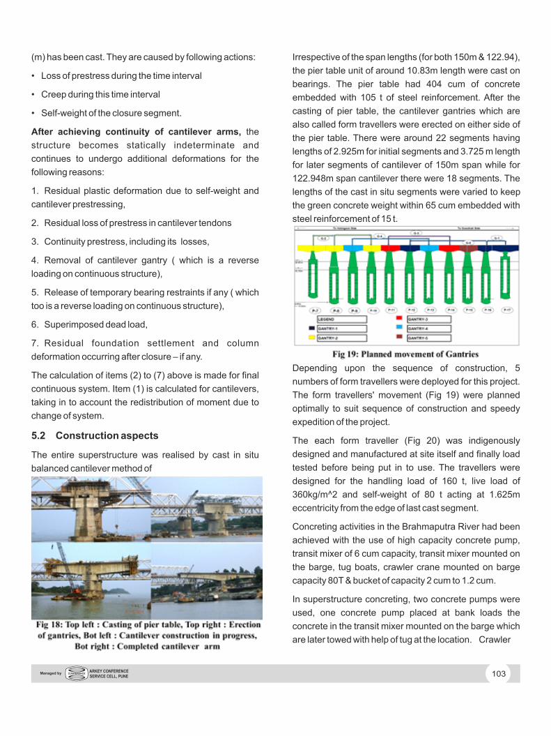
5.2 Construction aspects
The entire superstructure was realised by cast in situ
balanced cantilever method of
Irrespective of the span lengths (for both 150m & 122.94),
the pier table unit of around 10.83m length were cast on
bearings. The pier table had 404 cum of concrete
embedded with 105 t of steel reinforcement. After the
casting of pier table, the cantilever gantries which are
also called form travellers were erected on either side of
the pier table. There were around 22 segments having
lengths of 2.925m for initial segments and 3.725 m length
for later segments of cantilever of 150m span while for
122.948m span cantilever there were 18 segments. The
lengths of the cast in situ segments were varied to keep
the green concrete weight within 65 cum embedded with
steel reinforcement of 15 t.
Depending upon the sequence of construction, 5
numbers of form travellers were deployed for this project.
The form travellers' movement (Fig 19) were planned
optimally to suit sequence of construction and speedy
expedition of the project.
The each form traveller (Fig 20) was indigenously
designed and manufactured at site itself and finally load
tested before being put in to use. The travellers were
designed for the handling load of 160 t, live load of
360kg/m^2 and self-weight of 80 t acting at 1.625m
eccentricity from the edge of last cast segment.
Concreting activities in the Brahmaputra River had been
achieved with the use of high capacity concrete pump,
transit mixer of 6 cum capacity, transit mixer mounted on
the barge, tug boats, crawler crane mounted on barge
capacity 80T & bucket of capacity 2 cum to 1.2 cum.
In superstructure concreting, two concrete pumps were
used, one concrete pump placed at bank loads the
concrete in the transit mixer mounted on the barge which
are later towed with help of tug at the location. Crawler
103ARKEY CONFERENCE SERVICE CELL, PUNE
Managed by

crane mounted on the barge with concrete bucket helped
in lifting the concrete to the second concrete pump placed
on the deck for the further pumping. The whole cycle of
concreting in the river for the superstructure came to 8
cum per hour.
On an average following time cycle was achieved for
realization of a segment :
1) Gantry Unlocking : 1 Day
2) Gantry Movement : 0.5 Day
3) Gantry Locking : 1 Day
4) Gantry Alignment : 0.5 Day
5) Reinforcement fixing,
binding and fixing
of shuttering : 5 Days
6) Cable Profiling : 1 Day
7) Stopper Fixing/checking: 1 Day
8) Concreting : 1 Day
9) Cable threading/waiting period of concrete for
achieving 70% strength for post tensioning. : 5 Days
Total = 16 days.
During the construction as the cantilever progression
takes place, the deck had to be stabilised against the
overturning and also had to be restrained against
translation as most of the piers were supported on
longitudinally guided POT/PTFE bearings.
The 14 numbers of 19K15 stabilising (Fig 22) cables were
anchored to pier cap from bottom of pier table in addition
to 4 numbers of sand jacks. The translation or sliding of
the deck during construction was restrained by freezing
the bearings through end stoppers anchored by PT bars.
In order to be able to follow the evolution of cantilever
deflections towards the goal as indicated above in the
camber correction section, two survey points were
placed in the top slab concrete of each new segment, one
over the axis of each web, say 100mm behind the front
edge of the segment. The level of each point represented
the level of segment next to the segment joint in
subsequent survey checks. The longitudinal profile
constituted by the points would be a polygon whose
angles determine the final road profile.
When measured deflections were compared to the
predetermined ones, further corrections were to be
introduced in consideration of circumstances like the
following:
• Temperature difference due to solar radiation, heat of
hydration, etc,
• Any particular thermo-hygrometric condition e.g. high
humidity under bridge deck which passes at low height
over a water surface,
104ARKEY CONFERENCE SERVICE CELL, PUNE
Managed by

• Settlement / rotation of foundation, and
• Any additional load on the bridge, e.g. construction
load, furnishing, etc.
• The difference in the theoretical and actual creep and
shrinkage losses.
During the cantilever operation, the cantilever is the
system in constant evolution as such no fixed level is
available. The 'difference' between segment joints was
not only in level but also in slope.
The pre-pour survey check served to fine-tune the
traveller position in respect of the already built part of the
cantilever arm. The main concern was to set the traveller
to the right projection in respect of the previous segment.
At this time the deflection of the traveller proper had to be
introduced as an additional camber.
The post pour survey check served to determine the as-
built shape of the longitudinal profile in respect of the
desired profile at that step, in particular the position of the
newly poured segment with respect to the previous one.
In order to achieve the desired longitudinal Deck-profile,
the geometry control should focus on the difference of
slope as-built between subsequent segments; this could
be done graphically e.g. by drawing the longitudinal
profile made up by the bolts in each web line. Whenever
the discrepancy was detected between the desired curve
and as built curve, it had to be corrected over a few
following segments.
6.0 CONCLUSIONS
Bridging the mighty river Brahmaputra is one of the major
challenges for bridge engineers and could be done only
by an experienced and techno savvy bridge builder.
Some of the achievements while overcoming the
challenges were :
• Successful completion of 11 numbers of Double D
type Well Foundations with 57m avg. depth without any
major problems of tilt & shift in the river Brahmaputra.
• Continuous superstructure of Single PSC Box Girder
of 1494 m in length having an finger type expansion joints
at the ends of capacity 500mm with overall deck width of
13.875.
• Successful completion of shoring to maintain stability
of approach road of existing Saraighat Bridge.
• The use of STUs in large magnitude for the first time in
the country. Perhaps the adoption of the above STUs
helped in withstanding earthquake on 25th April' 2015 in
Nepal & North Eastern part of India on 7.3 in Richter
Scale. This Bridge structure under construction
sustained this massive earthquake without any damage.
• Indigenously designed, manufactured and load tested
5 numbers of gantries in use at a time.
• Specially designed stabilizing and bearing freezing
arrangement for peculiar bearing layout provided with in
bridge system.
• Special attention to pre camber monitoring during
superstructure construction.
7.0 REFERENCES
1. José Diogo Honório, Conceptual design of long-span
cantilever constructed concrete bridges, TRITA-BKN.
Master thesis 254, Structural Design & Bridges 2007
ISSN 1103-4297, ISRN KTH/BKN/EX—254—SE.
105ARKEY CONFERENCE SERVICE CELL, PUNE
Managed by

2. V N Heggade, Bearings & their configurations with in
bridge system, The bridge and Structural Engineer, Vol
43/Number 4/December 2013, pp 23-35.
3. Dr. V. K. Raina, Avinash Y. Mahendrakar, Amrendra N.
Singh, Philosophy of CAMBER-CORRECTION to obtain
correct deck-profile in cantilever construction….
Bhramaputra Bridge at Guwahati, India, ING-IABSE
seminar Mysore 2014 on Elevated transport corridors. Pp
160-169.
106ARKEY CONFERENCE SERVICE CELL, PUNE
Managed by