Embed Size (px)
Citation preview
1 | P a g e
PRE FEASIBILITY REPORT
FOR OBTAINING
PRIOR ENVIRONMENT CLEARANCE
FOR PROPOSED
1) Set up of 1 x50 TPH AFBC Boiler
and 2) Enhancement of CRM Production capacity from 0.8 MTPA to 1.0 MTPA
OF
JINDAL STAINLESS LIMITED
LOCATED AT
Kalinganagar Industrial Complex, Duburi, Dist. Jajpur - 755026, Orissa, India
Tel: +91 06726 266031 - 33 Fax: +91 06726 266006
E-mail: [email protected]
2016
2 | P a g e
Executive Summary Introduction of Project / Background Information
2.1 Identification of project and project proponent
2.2 Nature of the project
2.3 Need for the project and its importance to the country and or region
2.4 Demand-supply gap
2.5 Imports vs. indigenous production
2.6 Export possibility
2.7 Domestic / export markets
2.8 Employment generation (direct and indirect)
Project Description
3.1 Type of project including interlinked and interdependent Projects
3.2 Location with coordinates
3.3 Details of alternate sites & environmental considerations
3.4 Size or magnitude of operation
3.5 Project description with process details
3.6 Raw material required along with estimated quantity, likely source, marketing area of final
product’s mode of transport of raw material and finished product
3.7 Resource optimization/recycling and reuse envisaged in the project
3.8 Availability of water its source, energy/ power requirement and source
3.9 Quantity of wastes to be generated (liquid and solid) and scheme for their management
/disposal
3.10 Schematic representations of the feasibility drawing which give information of EIA purpose
Site Analysis
4.1 Connectivity
4.2 Land form, land use and land ownership
PPRREE FFEEAASSIIBBIILLIITTYY RREEPPOORRTT
INDEX
3 | P a g e
4.3 Topography
4.4 Existing land use pattern
4.5 Existing infrastructure
4.6 Soil classification
4.7 Climatic data from secondary sources
4.8 Social infrastructure available.
Planning Brief
5.1 Planning concept
5.2 Population projection
5.3 Land use planning (break up along with green belt etc.)
5.4Assessment of infrastructure demand (physical & social)
5.5 Amenities / facilities
Proposed Infrastructure
6.1 Industrial area (processing area)
6.2 Residential area (non processing area)
6.3 Green belt
6.4 Social infrastructure
6.5 Connectivity
6.6 Drinking water management (source & supply of water)
6.7 Sewarage system & Industrial waste management
6.8 Solid waste management
6.9 Power requirement & supply
Rehabilitation and resettlement plan
Project Schedule & Cost Estimates 8.1 Project schedule
8.2 Cost of the project Analysis of Proposal
Analysis of proposal (final recommendations)
9.1 Basic estimates
9.2 Project cost estimate
4 | P a g e
1.0 EXECUTIVE SUMMARY
Jindal Stainless Limited (JSL) is an Integrated Stainless Steel Plant of 1.6 MTPA, located at Kalinga
Nagar Industrial Complex (KNIC), Jajpur Road, Dist- Jajpur, Odisha. JSL is now intends to set up
additional 1 x50 TPH AFBC Boiler to supplement rated steam to the existing 13 MW TG along with
WHRB and associated finishing facilities of Cold Rolling Mill for enhancement of production capacity
from 0.8 MTPA to 1.0 MTPA.
By installation of the above facilities there will be no change in existing capacity of 1.6 MTPA
Integrated Stainless Steel productions at JSL.
There shall be no additional land requirement for this proposed project. The proposed project shall
come up inside the existing plant premises of JSL.
The total plant area available for the existing JSL complex is of 526.09 Hectares. The land required
inside the existing premises for set up of 1x50 TPH AFBC Boiler is approximately 1317 square
meters and 21340 square meters are to be required for enhancement of CRM Production capacity
from 0.8 MTPA to 1.0 MTPA.
The estimated Capital Cost for set up of 1x50 TPH AFBC Boiler is of 20 Crore and cost to be incurred
for installation of associated finishing facilities for enhancement of CRM production capacity from
0.8 MTPA to 1.0 MTPA is of 300 Crores. Hence total estimated cost for both the proposed project is
of 320 Crores which also includes the machinery cost to be incurred for installation of pollution
control equipments.
The total water required for both the proposed project will be approximately 1750 m3/d. Out of which 1150 m3/day water shall be required for operation of 1 x 50 TPH AFBC Boiler plant and 600 m3/day raw water shall be utilised for proposed additional project of CRM. Source of water shall be the RO treated waste water and the shortfall amount shall be sourced from River Brahmani for which permission has been obtained from Water Resource Department, Govt. of Odisha. Hence, there shall be no additional permission required from Water Resource Department, Govt. of Odisha for this proposed project. Green belt development is an ongoing process at JSL. Already 34 % (177 Hectares) of the total plant
area is under green belt coverage with suitable plant species have been planted all along the
internal road, raw material storage & handling, ash/dust prone areas. It is planned to plant further
saplings considering the parameters as type, height, leaf area, crown area, growing nature, water
requirement etc. Green belt will be progressively developed on land.
5 | P a g e
2.0 INTRODUCTION OF PROJECT / BACKGROUND INFORMATION 2.1 IDENTIFICATION OF THE PROJECT AND PROJECT PROPONENT Jindal Stainless Limited is one of the largest integrated manufacturers of stainless steel in India. A leader and a name synonymous with Enterprise, Excellence and Success, the company’s ethos mirrors most characteristics similar to the metal it produces; Akin to stainless steel Jindal Stainless Limited is innovative and versatile in its thought process; strong and unrelenting in its operations. The state-of-the-art unit of Jindal Stainless is located at Kalinga Nagar Industrial Complex, Jajpur Road, Dist-Jajpur in the state of Odisha. The plant is having the Integrated Stainless Steel production capacity of 1.6 MTPA with world class technology and equipments sourced from Siemens VAI, SMS Siemag and Andritz Sundwig.
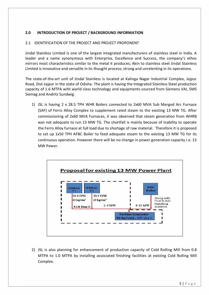
1) JSL is having 2 x 28.5 TPH WHR Boilers connected to 2x60 MVA Sub Merged Arc Furnace
(SAF) of Ferro Alloy Complex to supplement rated steam to the existing 13 MW TG. After
commissioning of 2x60 MVA Furnaces, it was observed that steam generation from WHRB
was not adequate to run 13 MW TG. The shortfall is mainly because of inability to operate
the Ferro Alloy furnace at full load due to shortage of raw material. Therefore it is proposed
to set up 1x50 TPH AFBC Boiler to feed adequate steam to the existing 13 MW TG for its
continuous operation. However there will be no change in power generation capacity i.e. 13
MW Power.
2) JSL is also planning for enhancement of production capacity of Cold Rolling Mill from 0.8
MTPA to 1.0 MTPA by installing associated finishing facilities at existing Cold Rolling Mill
Complex.
6 | P a g e
M/s. Jindal Stainless Limited is one of the largest stainless steel conglomerates in India and ranks
amongst the top 10 stainless steel conglomerates in the world. The promoters of the group are
highly qualified and have global experience in the field of Stainless Steel production.
2.2 NATURE OF THE PROJECT
As per EIA Notification 2006, the proposed project falls under Schedule in serial No. 3 (a) - Metallurgical Industry (ferrous & non- ferrous). As the existing project is a Integrated Stainless Steel Plant complex, the project is categorized as Category A as per EIA Notification, 2006. 2.3 NEED FOR THE PROJECT AND ITS IMPORTANCE TO THE COUNTRY AND/OR REGION
Due to rapid industrial & infrastructure development globally, there is constant increase in need of stainless
steel in the market today, stainless steel has already established itself in sectors like automotive, railway &
transport (ART), architecture, building & construction (ABC), chemical & petrochemical industries, capital
goods, kitchenware and food processing industries. Increasing number of sectors such as plumbing and
overhead water tanks are also realising the advantage of shifting to stainless steel. This environment-friendly
metal can be easily recycled.
2.4 DEMAND-SUPPLY GAP
The Indian Steel industry has entered into new development stage from 2005-2006 riding high on
the resurgent economy and rising demand of Steel. Rapid rise in production has resulted in India to
become 5th largest producer of Steel. It is estimated that, India’s Steel consumption will continue to
grow at nearly 16% rate annually, fuelled by the demand of construction project. The National Steel
Policy envisaged steel production to reach 110 million tonnes by 2020. So considering the huge
demand of steel, this project is important for partially fulfilling of demand. 2.5 IMPORTS VS. INDIGENOUS PRODUCTION
Imports are not expected to impose a significant threat to domestic players in future. 2.6 EXPORT POSSIBILITY First priority to meet domestic demand, should also take into account the large export possibilities. 2.7 DOMESTIC / EXPORT MARKETS The Stainless Steel shall be sold in domestic/global market. 2.8 EMPLOYMENT GENERATION (DIRECT & INDIRECT) DUE TO THE PROJECT Total manpower currently is 7500 including Contractor’s employee and additional about 100 manpower will be required during expansion excluding contractor’s employee. An equal number are expected to be in indirect employment.
7 | P a g e
3.0 PROJECT DESCRIPTION 3.1 TYPE OF PROJECT INCLUDING INTERLINKED AND INTERDEPENDENT PROJECTS
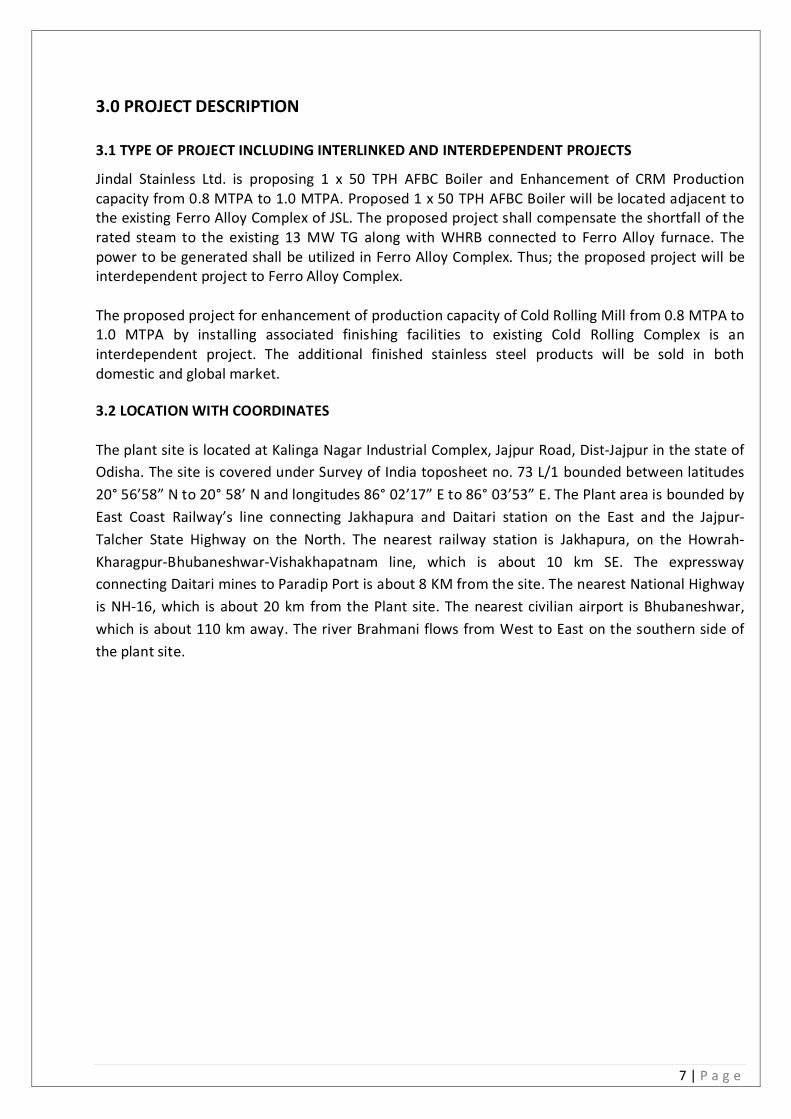
Jindal Stainless Ltd. is proposing 1 x 50 TPH AFBC Boiler and Enhancement of CRM Production capacity from 0.8 MTPA to 1.0 MTPA. Proposed 1 x 50 TPH AFBC Boiler will be located adjacent to the existing Ferro Alloy Complex of JSL. The proposed project shall compensate the shortfall of the rated steam to the existing 13 MW TG along with WHRB connected to Ferro Alloy furnace. The power to be generated shall be utilized in Ferro Alloy Complex. Thus; the proposed project will be interdependent project to Ferro Alloy Complex. The proposed project for enhancement of production capacity of Cold Rolling Mill from 0.8 MTPA to 1.0 MTPA by installing associated finishing facilities to existing Cold Rolling Complex is an interdependent project. The additional finished stainless steel products will be sold in both domestic and global market. 3.2 LOCATION WITH COORDINATES The plant site is located at Kalinga Nagar Industrial Complex, Jajpur Road, Dist-Jajpur in the state of
Odisha. The site is covered under Survey of India toposheet no. 73 L/1 bounded between latitudes
20° 56’58” N to 20° 58’ N and longitudes 86° 02’17” E to 86° 03’53” E. The Plant area is bounded by
East Coast Railway’s line connecting Jakhapura and Daitari station on the East and the Jajpur-
Talcher State Highway on the North. The nearest railway station is Jakhapura, on the Howrah-
Kharagpur-Bhubaneshwar-Vishakhapatnam line, which is about 10 km SE. The expressway
connecting Daitari mines to Paradip Port is about 8 KM from the site. The nearest National Highway
is NH-16, which is about 20 km from the Plant site. The nearest civilian airport is Bhubaneshwar,
which is about 110 km away. The river Brahmani flows from West to East on the southern side of
the plant site.
8 | P a g e
9 | P a g e
3.3 DETAILS OF ALTERNATE SITES & ENVIRONMENTAL CONSIDERATIONS
No alternative sites considered as the proposed expansion will be carried out in the existing Plant
premises of JSL.
3.4 SIZE OR MAGNITUDE OF OPERATION
JSL is proposed to set up 1 x50 TPH AFBC Boiler to supplement rated steam to the existing 13 MW
TG along with WHRB and associated finishing facilities of Cold Rolling Mill for enhancement of CRM
production capacity from 0.8 MTPA to 1.0 MTPA in its existing Plant premises.
The operational process includes basic raw material requirement, sizing of equipment, utilities and
services, infrastructure facilities and sources of waste generation, their quantity, treatment and
safe disposal of the waste.
3.5 PROJECT DESCRIPTION WITH PROCESS DETAILS M/s. Jindal Stainless Ltd. is proposing for set up 1 x50 TPH AFBC Boiler and enhancement of CRM
production capacity from 0.8 MTPA to 1.0 MTPA. Project description with process details of above
mentioned project are described below.
3.5.1 1 X 50 TPH AFBC BOILER
Main plant and Equipments:
The basis of technical parameters of the Boiler and Auxiliary equipment are discussed hereunder,
which describes the general requirements.
Feed water system:
Feed water system will be consisted of the following:
I. Deaerator Vapour tank/feed water storage tank.
II. Feed water pump.
III. Feed water control station.
Boiler Feed Water pumping station:-
Pumping station would be provided after the de-aerator on the water-side of the steam generator.
Pumps provide the necessary head for working medium (water) suitable for the boiler pressure
feed water pumping station is divided as follows;
I. Pump suction piping.
II. Feed pump
III. Cooling water system
IV. Minimum flow and balancing leak off line.
V. Pump discharge piping
10 | P a g e
Steam Generator
The boiler will be designed for 50 TPH steam generation, 51 kg/cm2.pressure, 405 ± 5 deg C super
heated steam output designed for firing with 100 % F grade coal. This boiler will be of Bi-Drum
design, Header type boiler tank, Natural circulation, water tube balanced draft, under bed fuel
feeding system, Bottom supported pressure parts and bed plate design.
Fuel combustion will be in an atmospheric bed combustor (AFBC) fixed at the boiler bottom. Fuel
will be stored in bunker. Drag chain feeders would be connected at the bottom of surge hoppers
(below the bunker).The fuel
As a complete unit the boiler plant would be equipped with the following circuits.
Feed water and steam system.
Pressure parts circuit.
Boiler steam circuit.
Boiler blow down circuit.
Sample coolers.
Chemical dosing system.
Combustor/Furnace.
Combustion Air/Over fire air system.
Fuel feeding system.
Start-up oil firing system.
Flue gas circuit.
Bed ash/Fly ash handling system.
Refractory and insulation.
Electric and Instrumentation.
Electrostatic precipitator.
Chimney.
The main parameters of the boiler will be:
Maximum continuous rating : 50 TPH
Steam pressure : 51 kg/cm2
Steam temperature : 405± 5 Deg C
Fuel Fired : F Grade Coal
The boiler will be divided into a combustion zone i.e. furnace and non-combustion zone i.e.
economizer, air heater etc. The furnace sides will be front and rear are of membrane panel
construction providing a gas tight sealing. For all the water wall bottom headers, Water would be
fed through supply pipes from down comers. The side wall, front wall, rear wall panel tubes top
headers would be connected to the steam drum through risers. The front wall panel tubes form the
roof of the furnace.
11 | P a g e
Feed water will be pumped by feed water pumps from deaerator to economizer through feed water
control station. The feed water from economizer outlet is then led to the steam drum. Steam will
be generated in the furnace membrane wall tubes. The resulting water-steam mixture from the
riser tubes of membrane panel returns to the steam drum where the separation of steam from
water takes place. The saturated seam is led through the supply pipes to the PSH inlet header. From
the PSH inlet header steam passes through the coils to PSH o/l header, then steam is led to
Attemperator and then the Sec SH inlet header. Finally from the SSH outlet header steam will be
passed to the main steam will be passed to the main steam line to steam header.
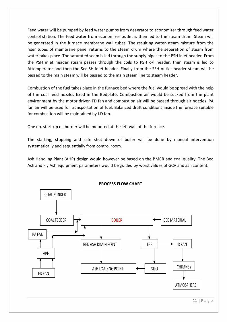
Combustion of the fuel takes place in the furnace bed where the fuel would be spread with the help
of the coal feed nozzles fixed in the Bedplate. Combustion air would be sucked from the plant
environment by the motor driven FD fan and combustion air will be passed through air nozzles .PA
fan air will be used for transportation of fuel. Balanced draft conditions inside the furnace suitable
for combustion will be maintained by I.D fan.
One no. start-up oil burner will be mounted at the left wall of the furnace.
The starting, stopping and safe shut down of boiler will be done by manual intervention
systematically and sequentially from control room.
Ash Handling Plant (AHP) design would however be based on the BMCR and coal quality. The Bed
Ash and Fly Ash equipment parameters would be guided by worst values of GCV and ash content.
PROCESS FLOW CHART
12 | P a g e
3.5.2 ENHANCEMENT OF CRM PRODUCTION CAPACITY FROM 0.8 MTPA TO 1.0 MTPA
JSL is planning an expansion to increase the production capacity of its CRAP product by a quantity of
2,00,000 MT annually by installing following machinery and equipment in its existing CRM Facility in
Jajpur, Orissa.
2 Nos. of 20 HI Cold Rolling Mill
4 Nos. of Bright Annealing Line
1 No. of Pickling Line
2 Nos. of Slitting Line
20 HI COLD ROLLING MILL
The 20 HI Cold Rolling Mills will consist of main rolling mill stand, terminal equipment and other
accessories.
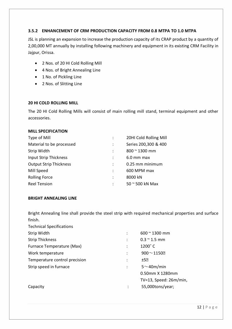
MILL SPECIFICATION
Type of Mill : 20HI Cold Rolling Mill
Material to be processed : Series 200,300 & 400
Strip Width : 800 ~ 1300 mm
Input Strip Thickness : 6.0 mm max
Output Strip Thickness : 0.25 mm minimum
Mill Speed : 600 MPM max
Rolling Force : 8000 kN
Reel Tension : 50 ~ 500 kN Max
BRIGHT ANNEALING LINE
Bright Annealing line shall provide the steel strip with required mechanical properties and surface
finish.
Technical Specifications
Strip Width : 600 ~ 1300 mm
Strip Thickness : 0.3 ~ 1.5 mm
Furnace Temperature (Max) : 1200˚ C
Work temperature : 900~1150
Temperature control precision : ±5
Strip speed in furnace : 5~40m/min
0.50mm X 1280mm
TV=13, Speed: 26m/min,
Capacity : 55,000tons/year;
13 | P a g e
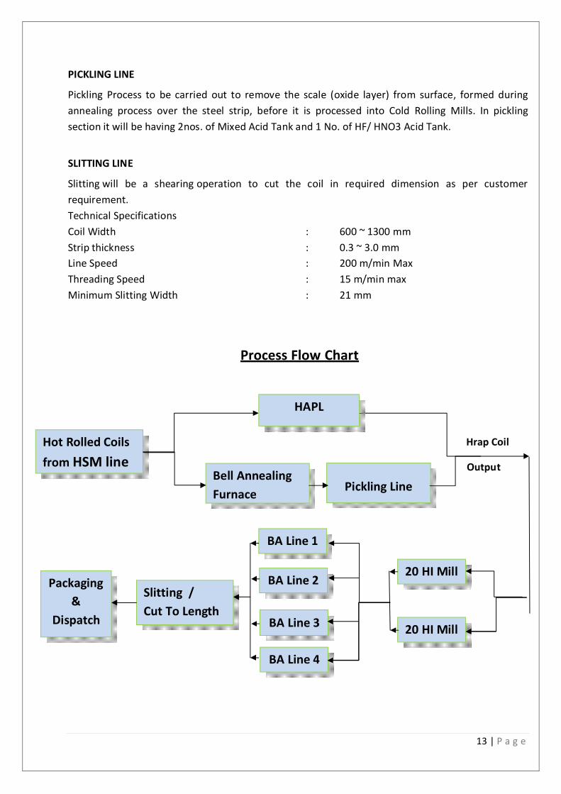
PICKLING LINE
Pickling Process to be carried out to remove the scale (oxide layer) from surface, formed during
annealing process over the steel strip, before it is processed into Cold Rolling Mills. In pickling
section it will be having 2nos. of Mixed Acid Tank and 1 No. of HF/ HNO3 Acid Tank.
SLITTING LINE
Slitting will be a shearing operation to cut the coil in required dimension as per customer
requirement.
Technical Specifications
Coil Width : 600 ~ 1300 mm
Strip thickness : 0.3 ~ 3.0 mm
Line Speed : 200 m/min Max
Threading Speed : 15 m/min max
Minimum Slitting Width : 21 mm
Process Flow Chart
Hrap Coil
Output
Hot Rolled Coils
from HSM line Bell Annealing
Furnace
Slitting /
Cut To Length
20 HI Mill
Pickling Line
20 HI Mill
BA Line 1
BA Line 2
BA Line 3
BA Line 4
Packaging
&
Dispatch
HAPL
14 | P a g e
3.6 RAW MATERIAL REQUIRED ALONG WITH ESTIMATED QUANTITY, LIKELY SOURCE, MARKETING
AREA OF FINAL PRODUCT’S MODE OF TRANSPORT OF RAW MATERIAL AND FINISHED
PRODUCT Major raw materials required for 1 x 50 TPH AFBC Boiler will be Coal and Bio-mass of 550 TPD
approx. which will be received by railways and road. Major final product of CRM will be transported
through railway line with the help of our own railway siding.
3.7 RESOURCE OPTIMIZATION/RECYCLING AND REUSE ENVISAGED IN THE PROJECT
Fly ash to be generated will be sent to brick manufacturing and asbestos manufacturing
plants. Bottom ash to be sent to existing ash pond in slurry form through pipeline.
No other major solid waste generation from the plant has been envisaged. However,
material collected by the dust collectors (Bag Filters) will automatically be recycled in the
process.
STP treated water will be used for plantation and sludge will be utilized as manure for green
belt development
Acidic waste effluent to come up from proposed pickling line of CRM Complex shall be
treated in our existing ETP of CRM Complex and further reuse in various plant activities.
There will no discharge to outside from the project premises. 3.8 AVAILABILITY OF WATER ITS SOURCE, ENERGY/ POWER REQUIREMENT AND SOURCE
The total water required for both the proposed project will be approximately 1750 m3/day. Out of which 1150 m3/day water shall be required for operation of 1 x 50 TPH AFBC Boiler plant and rest 600 m3/day raw water shall be required for proposed additional project of CRM. Source of water shall be the RO treated waste water and the shortfall amount shall be sourced from River Brahmani for which permission has been obtained from Water Resource Department, Govt. of Odisha. Hence, there shall be no additional permission required from Water Resource Department, Govt. of Odisha for this proposed project. 3.9 QUANTITY OF WASTES TO BE GENERATED (LIQUID AND SOLID) AND SCHEME FOR THEIR
MANAGEMENT /DISPOSAL For the proposed project fly ash to be generated shall be sent to brick manufacturers and asbestos manufacturers for 100 % utilization. Bottom ash shall be sent to existing bottom ash pond. It is also proposed to install a neutralization pit where proper neutralizing arrangement for treatment of the effluent coming from CPP to be carried out and the treated effluent will be reused in in-house plant activities. Acidic waste effluent to come up from proposed pickling line of CRM Complex shall be treated in our existing ETP of CRM Complex and further reuse in various plant activities.
3.10 SCHEMATIC REPRESENTATIONS OF THE FEASIBILITY DRAWING WHICH GIVE INFORMATION
OF EIA PURPOSE
Process Flow sheet for both the proposed project is given in section 3.5 of this report.
15 | P a g e
4.0 SITE ANALYSIS
4.1 CONNECTIVITY
The site of the stainless steel plant is located in Jajpur district of Orissa. The site is covered under
Survey of India toposheet no. 73 L/1 bounded between latitudes 20° 56’58” N to 20° 58’ N and
longitudes 86° 02’17” E to 86° 03’53” E. The plant area is bounded by East Coast Railway’s line
connecting Jakhapura and Daitari station on the east and the Jajpur- Talcher State Highway on the
north. The nearest railway station is Jakhapura, on the Howrah-Kharagpur-Bhubaneshwar-
Vishakhapatnam line, which is about 10 km towards SE. The expressway connecting Daitari mines to
Paradip Port is about 8 km W from the site. The nearest National Highway is NH-6, which is about
20 km E of the plant at its nearest point. The nearest civilian airport is Bhubaneshwar, which is
more than 110 km away. The proposed project area falls within Duburi village. The river Brahmani
flows from west to east on the southern side of the plant site.
4.2 LAND FORM, LAND USE AND LAND OWNERSHIP
The exiting land is industrial land. Addition of new products will be carried out within existing premises. No new land is required for the proposed set up. The proposed project will not cause any permanent or temporary change to land use. 4.3 TOPOGRAPHY
As no new major construction/land required due to addition of new products, topography will not
be changed .The study area forms part of inland tract and are characterized by flat terrain .
4.4 EXISTING LAND USE PATTERN The existing land is used for industrial purpose. No additional land will be required for proposed plant.
4.5 EXISTING INFRASTRUCTURE
Existing infrastructure includes provisions of appropriate water supply, power connection, storage
facilities for raw-material and products and production, utility sheds and administrative office.
4.6 SOIL CLASSIFICATION
As no new construction/land required due to addition of new products, soil classification will not changed.
4.7 CLIMATIC DATA FROM SECONDARY SOURCES
As no new construction/land required due to addition of new products, climate will not changed.
4.8 SOCIAL INFRASTRUCTURE AVAILABLE
Already a well establish social infrastructure is available in and around the plant site as the plant
area comes under Kalinga Nagar Industrial Complex.
5.0 PLANNING BRIEF
16 | P a g e
5.1 PLANNING CONCEPT (TYPE OF INDUSTRIES, FACILITIES, TRANSPORTATION ETC.) TOWN AND COUNTRY PLANNING / DEVELOPMENT AUTHORITY CLASSIFICATION
The proposed project will be located inside the existing premises of Jindal Stainless Limited. at Kalinga Nagar Industrial Complex, Jajpur Road Dist-Jajpur, Odisha. The proposed project is a part of integrated stainless steel plant with 1 x50 TPH AFBC Boiler to supplement rated steam to the existing 13 MW TG along with WHRB and associated finishing facilities of Cold Rolling Mill for enhancement of production capacity from 0.8 MTPA to 1.0 MTPA. Infrastructure facilities in this Kalinganagar Industrial Complex are well developed and have well connectivity by road and rail. The nearest town Jajpur Road is 12.0 km away and easily accessible by road where all facilities such as schools, collages, hospitals and markets are available. 5.2 POPULATION PROJECTION
In the area, trained manpower is already available and in the proposed project local workers will be given priorities for employment. There will not be significant increase in population due to proposed project as this is a very small project. The additional people influx due to the proposed project can be easily accommodated in the Jajpur Road and nearby villages. The development of new residential facility is not anticipated.
5.3 LAND USE PLANNING (BREAKUP ALONG WITH GREEN BELT ETC.).
The proposed expansion project will be located inside the existing premises of Jindal Stainless Limited. at Kalinga Nagar Industrial Complex, Jajpur Road, Dist Jajpur, Orissa and land use is already notified as Industrial purpose. The proposed project will be constructed with well developed green belt all around the boundary of the plots as well as all around the various units. Total land of the entire JSL Complex is 526.09 Ha and out of which 177 Ha. (34 %) has been covered under green belt development. Suitable plant species has been planted all along the plant premises in consultation with the forest department. However, green belt development is a ongoing process at JSL. 5.4 ASSESSMENT OF INFRASTRUCTURE DEMAND (PHYSICAL & SOCIAL) The road and rail infrastructure is already well developed in the area which requires for the transport of the raw material and finished goods to the various part of the country. The manpower is local and their social infrastructure is also developed. The inflow of money in terms of direct and indirect employment will further improve the physical and social infrastructure.
5.4 AMENITIES / FACILITIES
As all the additional amenities and facilities for drinking water, medical dispensary first aid box, communication facilities, emergency vehicle for shifting the workers during accident etc. are available with the existing plant; the same can cater the need for this proposed project.
17 | P a g e
6.0 PROPOSED INFRASTICTURE
6.1 INDUSTRIAL AREA (PROCESSING AREA)
The infrastructural facilities are already developed in the premises of the unit as per the requirement and additional facilities for the expansion purpose will be provided as per the requirement.
6.2 RESIDENTIAL AREA (NON – PROCESSING AREA)
The development of residential area has not envisaged.
6.3 GREEN BELT
The greenbelt coverage area is more than 34% (177.47 Ha) of the total plant area.
6.4 SOCIAL INFRASTRUCTURE
The social infrastructure in the region is well developed due to plant area come under Kalinganagar Nagar Indtrial Complex .
6.5 CONNECTIVITY (TRAFFIC AND TRANSPORTATION ROAD / RAIL / METRO / WATERWAYS ETC.)
The connectivity in terms of traffic, transportation road is already developed and good. There are well connected roads in the area. The nearest railway station is existing at Sukinda Road which is at 2.5 KM from the plant site. 6.6 DRINKING WATER MANAGEMENT (SOURCE & SUPPLY OF WATER). Source of water for the plant is from River Brahmani. Water treatment plant is available inside the plant for treatment of river water. Further drinking water filtration units are available at all sections and subsections of the plant.
6.7 SEWERAGE SYSTEM
Sewage treatment plant has been provided for the treatment of domestic effluent and treated effluent will be utilized for green belt development. INDUSTRIAL WASTE MANAGEMENT (LIQUID EFFLUENT)
A neutralisation pit has been envisaged for 1 x 50 TPH AFBC Boiler for treatment of cooling tower blow down, Boiler Blow down, DM Plant rejects. Further shall be used in slurry preparation of bottom ash.
For effluents generated from proposed plant facilities of CRM, existing ETP of CRM will cater the need for treatment and further shall be reused in plant activities.
18 | P a g e
6.8 SOLID WASTE MANAGEMENT 6.8.1 1 X 50 TPH AFBC BOILER The company will make inventory of all types of solid waste that are expected during the construction activity before standing the work. The transportation of construction spoil will be allowed only to designed dumpsites. Careful design, planning and good site management would minimize waste of materials such as concrete, mortars and cement grouts. Construction waste will be segregated as much as possible at site itself to increase the feasibility of recycling concrete and masonry as filling material and steel pieces as saleable scrap. Litter disposal and collection points will be established sound the construction work sites. The various waste materials arising out of the technological processes would be reutilized to the extent possible. Coal ash will be utilized for cement making, brick making, low /waste land reclamation, etc. and the unutilized portion will be used to backfill nearby abandoned mines. Soiled cotton / cloth wastes (generated during cleaning of machines and equipment) will be collected in bins burnt in the furnace of steel melting shop. Electric wastes and used batteries will be collected and given to authorized recyclers. Domestic garbage will be collected from the township and plant in containers; biodegradable, inserts and non-bio gradable materials in segregated manner. The biodegradable material will be composed and used as manure inside the premises. Recyclable materials like packaging materials, empty drums, bottles, glass, metals, paper, plastic, etc. will be given to recyclers. Non-recyclable materials will be disposed in sanitary landfill sites as per the local laws and regulations. 6.9.2 ENHANCEMENT OF CRM PRODUCTION CAPACITY FROM 0.8 MTPA TO 1.0 MTPA The company will make inventory of all types of solid waste that are expected during the construction activity before standing the work. The transportation of construction spoil will be allowed only to designed dumpsites. Careful design, planning and good site management would minimize waste of materials such as concrete, mortars and cement grouts. Construction waste will be segregated as much as possible at site itself to increase the feasibility of recycling concrete and masonry as filling material and steel pieces as saleable scrap. Litter disposal and collection points will be established sound the construction work sites. The various waste materials arising out of the technological processes would be reutilized to the extent possible. The mill scale generated from the process will be reutilised in the integrated steel plant. The ETP sludge will be disposed off in TSDF 6.10 POWER REQUIRMENT & SUPPLY /STORES 6.10.1 1 X 50 TPH AFBC BOILER Power requirement for this will be sourced from own power station of JSL. The proposing 50 TPH
AFBC Boiler to be located inside existing premises to supplement the steam required for 13 MW
Turbine along with WHRB attached to 2x60 MVA SAF’s.
6.10.2 ENHANCEMENT OF CRM PRODUCTION CAPACITY FROM 0.8 MTPA TO 1.0 MTPA Power requirement is 32 MVA which will be sourced from own power station of JSL.
19 | P a g e
7.0 REHABILITATION AND RESETTLEMENT PLAN No rehabilitation and resettlement plan has been made as the area designated for the project is
situated inside the JSL plant premises. The plant and allied activities will provide job opportunities
for eligible persons and many will find employment in ancillary & other services connected with this
project. The proposed long term activity will open up market and opportunities growth for self
employed and cultivators. To this extent, the impact will be significantly beneficial since un-
employment and under employment is the main socio-economic problem faced by the people in
this area
20 | P a g e
8.0 PROJECT SCHEDULE AND COST OF ESTIMATES 8.1 1 X 50 TPH AFBC BOILER The estimated capital cost of the plant worked out to be Rs 20Cr. This is covering the cost of main plant, auxiliary plant, equipments, pollution control etc. 8.2 ENHANCEMENT OF CRM PRODUCTION CAPACITY FROM 0.8 MTPA TO 1.0 MTPA The estimated capital cost of the plant worked out to be Rs 300Cr. This is covering the cost of main plant, auxiliary plant, equipments, pollution control etc. The completion schedule of the proposed plant is 12 months from zero date. 9.0 ANALYSIS OF PROPOSAL (FINAL RECOMMENDATIONS)
The proposed project will improve the economic condition of the area and local people. The employment of local people in primary and secondary sectors of project will upgrade the prosperity of the region.