Embed Size (px)
Citation preview
An award providing opportunity for water industry operational staff to share their in the field innovations & fixes to problems so that others in the water industry can benefit.
2015 PASS Award Winner Frank Rinaldo from North East Water with Jillian Busch (L) and David Barry (R) from Aqualift Project Delivery
2015
2015
WINNE
RWIN
NER
2015 WINNER Frank Rinaldo Sluice Valve Top Remover Tool
Mark ChilinskiWinneke Alum Injection Line Dilution
Marty HaynesFloating Magazine Type Chlorine Pill Dispenser
Ben OtteryFilter Inspection Extension Arm
Victor PalmerBiofilm Removal at Yarra Glen Treatment Plant
2
4
6
8
10
Contents
2015
2015
WINN
ER
WINN
ER
Sluice Valve Top Remover Tool Frank Rinaldo, Operations Officer - Myrtleford, North East WaterTHE PROBLEM The problem was the time it took to remove the top of a sluice valve to access the packing to install new rubber cones to seal any leaks. A large hole (1 m diameter) was required to access the top of the sluice valve to be able to have enough room to leverage a wedge under it so it could be hit numerous times with a sledge hammer to loosen the top and remove it. Most of the old mains were put in very deep so as you can imagine it was very time consuming and labour intensive job to dig such a large diameter hole just to remove the top of the sluice valve. This was a common activity that required the better part of a day to complete.
How did the problem impact you or your work situation?
In certain situations (near roads, on footpaths, in public areas etc) it was difficult to dig such a large hole just to remove the top of the sluice valve. These large holes also posed a safety risk of traffic and manual handling if they needed to be dug in roads or under concrete. The large holes also posed a risk to onlookers if they were dug in public places, and hence required barricading and signs which added to the time it took to complete the job before I constructed this tool.
How long had the problem been occurring? The problem has been occurring ever since sluice valves were put into the retic, well before I started in the water industry. As we now use the tool I developed all the time to remove the tops of sluice valves, there is no need to dig the large hole previously required to conduct the job, consequently we don’t have any pictures of the problem before I developed this tool. However below is a demonstration of the problem.
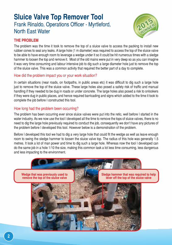
Before I developed this tool we had to dig a very large hole that could fit the wedge as well as leave enough room to swing the sledge hammer to loosen the sluice valve top. The radius of this hole was generally 1.5 metres. It look a lot of man power and time to dig such a large hole. Whereas now the tool I developed can do the same job in a hole 1/10 the size, making this common task a lot less time consuming, less dangerous and less impacting to the environment.
Wedge that was previously used to remove the top of the sluice valve
Sledge hammer that was required to help lever off the top of the sluice valve
2
THE SOLUTIONAfter digging up so many sluice valves, I thought there must be an easier way to remove the top of them without digging such a large diameter hole. So I thought of ways to make a tool that could be used to leverage the top off in a narrow space. That was when I started developing this tool.
Who helped work on the solution?I worked on this solution by myself, and now all the Operators have one in their work utes.
Describe the solution.The solution is a tool consisting of a metal rod with two pronged slides at the bottom that you slip under the base of the sluice valve top. There is a heavy metal sleeve that slides up and down along the rod. The sleeve hits a metal stopper at the top of the rod, effectively creating a jackhammer action and allowing the sluice valve top to be lifted. The job can now be carried out on ground level without having to dig a large 1 metre diameter hole just to get the top of the sluice valve to replace the rubber cones. The hole now only has to be 10 cm in diameter and easily dug using a jetter. Even if the bolt securing the valve key head sheared off while trying to remove it you could still hammer it off and not have to cut it off.
How has it helped you at work?The tool has greatly reduced the time it takes to remove the top and packing flange of a sluice valve to install new rubber cones to stop leaks. Instead of taking 3-8 hours the job now takes 1-2 hours. The tool has also reduced safety risks with the job; these include manual handling to dig such a large hole, trips and falls caused by the hole and traffic risks at times when the sluice valve is under a road.
Suggest improvements.The prototype has worked very well which is why it’s still the one we use today. However future tools could be made a bit more heavy duty.
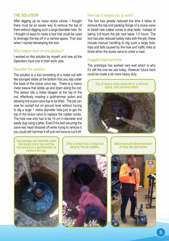
Tool prongs are inserted under the sluice valve top and the
tool works as a jackhammer to remove the top.
Above ground demonstration of how the tool works
Only a small hole is required (dug by the jet rodder).
Top of sluice valve removed in a minimal space, with minimal effort.
3
Winneke Alum Injection Line Dilution Mark Chilinski, Water Supply Officer, Melbourne WaterTHE PROBLEM Winneke Treatment Plant is designed to produce up to 560 ML/d. The treatment process includes clarification, filtration, chlorination, fluoridation and pH correction. Aluminium Sulphate is the primary coagulant used in the clarification process.
The Alum dosing lines at Winneke are approximately 120 m long before being mixed with service water prior to injection into the Plant raw water inlet structure. The return sample loop time before the dosed water analyser recognises a change in dose can be up to one hour when the plant is operating at minimum flow rates. Whenever dosing line duties were rotated the plant experienced high dosed water pH alarms, often exceeding our allowable HACCP limits. Further investigations proved that at the point of service water addition a syphoning and dilution effect was occurring on the Alum solution in the standby line whilst it was not in operation. This problem had become more evident as the plant is currently operating at very low flows therefore increasing the turnover time of the Alum solution.
How did the problem impact you or your work situation?The high pH alarms required us to manually manipulate the Alum dosing pump outputs every time we changed pump duties to avoid water quality incidents and improve the continuity in alum dosing for optimal coagulation pH. It also required us to produce multiple excursion reports to capture each pH event
How long had the problem been occurring?The problem was inherent in the original plant design which has been in operation over 30 years but at typical higher flows it was not so evident due to quicker turnover of the Alum solution at the higher dose rates. Our current operating environment requires us to run at much lower plant flows even to the point of running the plant in Start – Stop mode which requires regular duty changeovers. As a result this problem has become significantly more evident over the past 24 months.
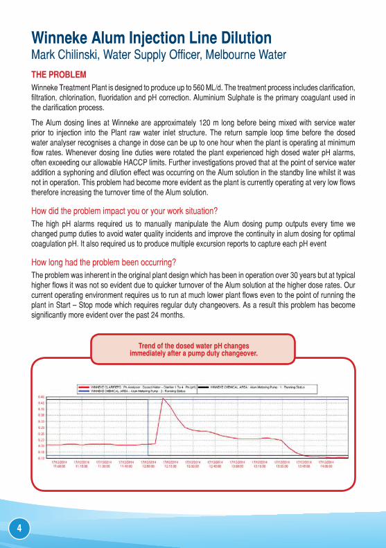
Trend of the dosed water pH changes immediately after a pump duty changeover.
4
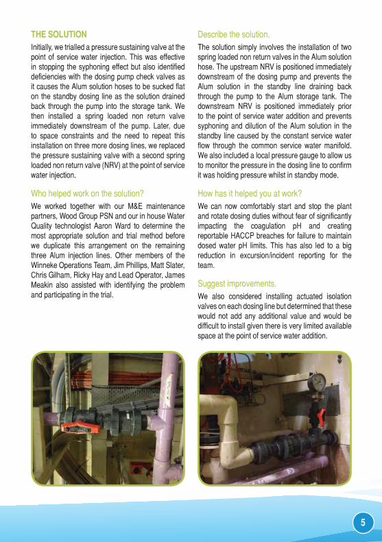
THE SOLUTIONInitially, we trialled a pressure sustaining valve at the point of service water injection. This was effective in stopping the syphoning effect but also identified deficiencies with the dosing pump check valves as it causes the Alum solution hoses to be sucked flat on the standby dosing line as the solution drained back through the pump into the storage tank. We then installed a spring loaded non return valve immediately downstream of the pump. Later, due to space constraints and the need to repeat this installation on three more dosing lines, we replaced the pressure sustaining valve with a second spring loaded non return valve (NRV) at the point of service water injection.
Who helped work on the solution?We worked together with our M&E maintenance partners, Wood Group PSN and our in house Water Quality technologist Aaron Ward to determine the most appropriate solution and trial method before we duplicate this arrangement on the remaining three Alum injection lines. Other members of the Winneke Operations Team, Jim Phillips, Matt Slater, Chris Gilham, Ricky Hay and Lead Operator, James Meakin also assisted with identifying the problem and participating in the trial.
Describe the solution.The solution simply involves the installation of two spring loaded non return valves in the Alum solution hose. The upstream NRV is positioned immediately downstream of the dosing pump and prevents the Alum solution in the standby line draining back through the pump to the Alum storage tank. The downstream NRV is positioned immediately prior to the point of service water addition and prevents syphoning and dilution of the Alum solution in the standby line caused by the constant service water flow through the common service water manifold. We also included a local pressure gauge to allow us to monitor the pressure in the dosing line to confirm it was holding pressure whilst in standby mode.
How has it helped you at work?We can now comfortably start and stop the plant and rotate dosing duties without fear of significantly impacting the coagulation pH and creating reportable HACCP breaches for failure to maintain dosed water pH limits. This has also led to a big reduction in excursion/incident reporting for the team.
Suggest improvements.We also considered installing actuated isolation valves on each dosing line but determined that these would not add any additional value and would be difficult to install given there is very limited available space at the point of service water addition.
5
Floating Magazine Type Chlorine Pill Dispenser
Marty Haynes, Water Plant Operator, Port Macquarie-Hastings CouncilTHE PROBLEM It is difficult to maintain adequate chlorine levels in reservoirs with low demand. Reservoirs need to be manually dosed with chlorine pills but current methods including floating pool dispensers and floating baskets are inadequate because all pills dissolve at the same time which creates a spike in levels that quickly dissipates over a few days.
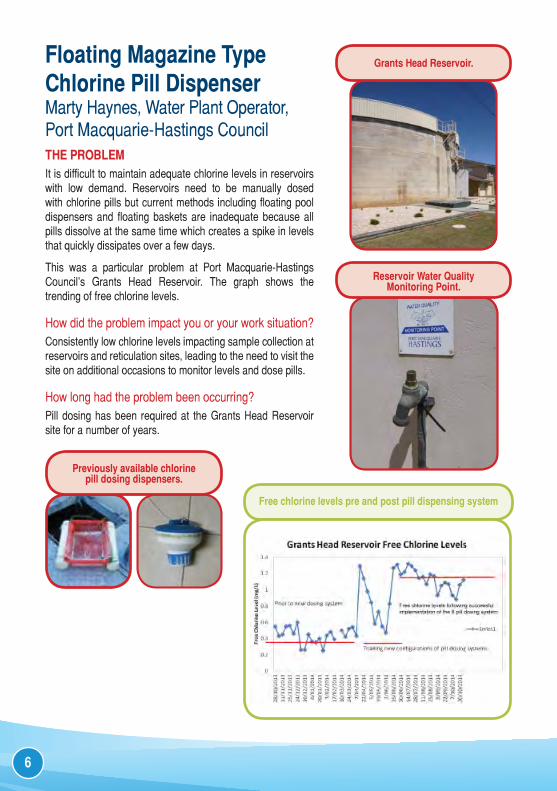
This was a particular problem at Port Macquarie-Hastings Council’s Grants Head Reservoir. The graph shows the trending of free chlorine levels.
How did the problem impact you or your work situation?Consistently low chlorine levels impacting sample collection at reservoirs and reticulation sites, leading to the need to visit the site on additional occasions to monitor levels and dose pills.
How long had the problem been occurring? Pill dosing has been required at the Grants Head Reservoir site for a number of years.
Previously available chlorine pill dosing dispensers.
Grants Head Reservoir.
Reservoir Water Quality Monitoring Point.
Free chlorine levels pre and post pill dispensing system
6
THE SOLUTIONI wanted to provide a longer lasting chlorine pill dispenser to reduce the required number of visits to the Reservoir site and ensure adequate chlorine disinfection was taking place.
Who helped work on the solution?As the designated operator for the water quality sampling runs in this area, I investigated and implemented this solution for the problem.
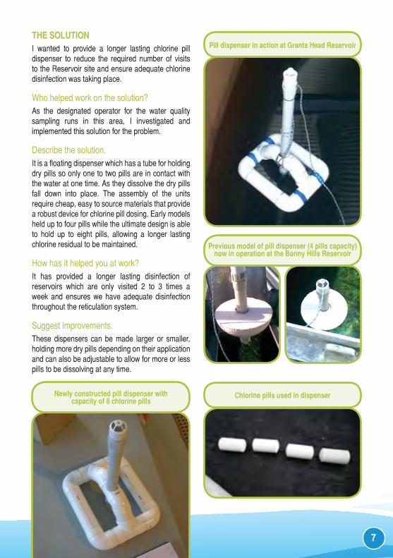
Describe the solution.It is a floating dispenser which has a tube for holding dry pills so only one to two pills are in contact with the water at one time. As they dissolve the dry pills fall down into place. The assembly of the units require cheap, easy to source materials that provide a robust device for chlorine pill dosing. Early models held up to four pills while the ultimate design is able to hold up to eight pills, allowing a longer lasting chlorine residual to be maintained.
How has it helped you at work?It has provided a longer lasting disinfection of reservoirs which are only visited 2 to 3 times a week and ensures we have adequate disinfection throughout the reticulation system.
Suggest improvements.These dispensers can be made larger or smaller, holding more dry pills depending on their application and can also be adjustable to allow for more or less pills to be dissolving at any time.
Previous model of pill dispenser (4 pills capacity) now in operation at the Bonny Hills Reservoir
Newly constructed pill dispenser withcapacity of 8 chlorine pills
Pill dispenser in action at Grants Head Reservoir
Chlorine pills used in dispenser
7
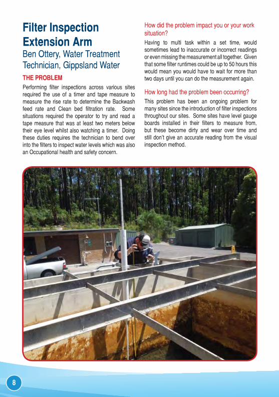
Filter Inspection Extension ArmBen Ottery, Water Treatment Technician, Gippsland WaterTHE PROBLEM Performing filter inspections across various sites required the use of a timer and tape measure to measure the rise rate to determine the Backwash feed rate and Clean bed filtration rate. Some situations required the operator to try and read a tape measure that was at least two meters below their eye level whilst also watching a timer. Doing these duties requires the technician to bend over into the filters to inspect water levels which was also an Occupational health and safety concern.
How did the problem impact you or your work situation?Having to multi task within a set time, would sometimes lead to inaccurate or incorrect readings or even missing the measurement all together. Given that some filter runtimes could be up to 50 hours this would mean you would have to wait for more than two days until you can do the measurement again.
How long had the problem been occurring? This problem has been an ongoing problem for many sites since the introduction of filter inspections throughout our sites. Some sites have level gauge boards installed in their filters to measure from, but these become dirty and wear over time and still don’t give an accurate reading from the visual inspection method.
8
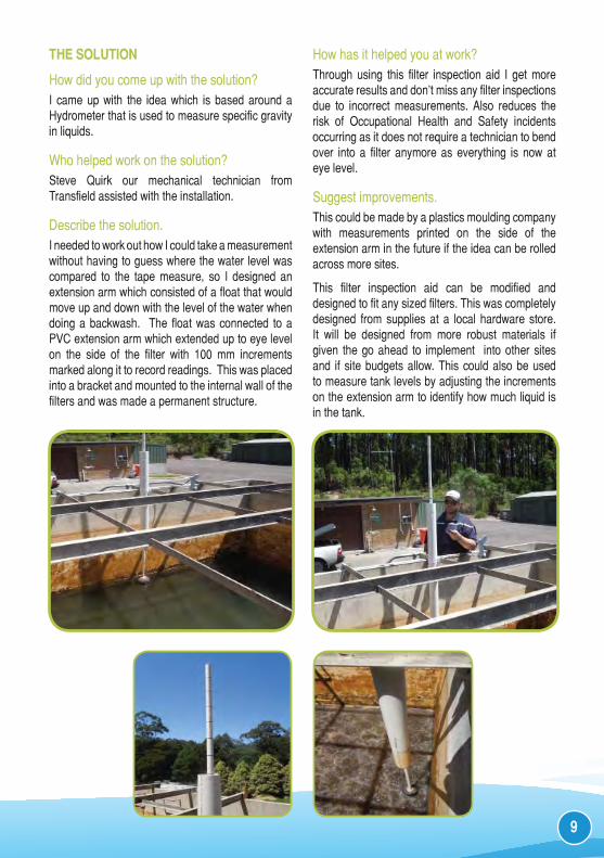
THE SOLUTION
How did you come up with the solution?I came up with the idea which is based around a Hydrometer that is used to measure specific gravity in liquids.
Who helped work on the solution?Steve Quirk our mechanical technician from Transfield assisted with the installation.
Describe the solution.I needed to work out how I could take a measurement without having to guess where the water level was compared to the tape measure, so I designed an extension arm which consisted of a float that would move up and down with the level of the water when doing a backwash. The float was connected to a PVC extension arm which extended up to eye level on the side of the filter with 100 mm increments marked along it to record readings. This was placed into a bracket and mounted to the internal wall of the filters and was made a permanent structure.
How has it helped you at work?Through using this filter inspection aid I get more accurate results and don’t miss any filter inspections due to incorrect measurements. Also reduces the risk of Occupational Health and Safety incidents occurring as it does not require a technician to bend over into a filter anymore as everything is now at eye level.
Suggest improvements.This could be made by a plastics moulding company with measurements printed on the side of the extension arm in the future if the idea can be rolled across more sites.
This filter inspection aid can be modified and designed to fit any sized filters. This was completely designed from supplies at a local hardware store. It will be designed from more robust materials if given the go ahead to implement into other sites and if site budgets allow. This could also be used to measure tank levels by adjusting the increments on the extension arm to identify how much liquid is in the tank.
9
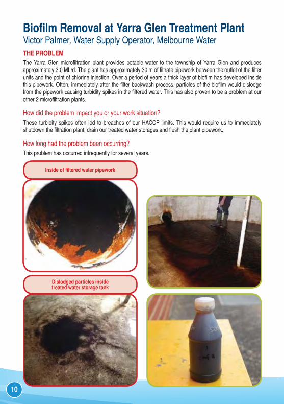
Biofilm Removal at Yarra Glen Treatment PlantVictor Palmer, Water Supply Operator, Melbourne WaterTHE PROBLEM The Yarra Glen microfiltration plant provides potable water to the township of Yarra Glen and produces approximately 3.0 ML/d. The plant has approximately 30 m of filtrate pipework between the outlet of the filter units and the point of chlorine injection. Over a period of years a thick layer of biofilm has developed inside this pipework. Often, immediately after the filter backwash process, particles of the biofilm would dislodge from the pipework causing turbidity spikes in the filtered water. This has also proven to be a problem at our other 2 microfiltration plants.
How did the problem impact you or your work situation?These turbidity spikes often led to breaches of our HACCP limits. This would require us to immediately shutdown the filtration plant, drain our treated water storages and flush the plant pipework.
How long had the problem been occurring?This problem has occurred infrequently for several years.
Dislodged particles inside treated water storage tank
Inside of filtered water pipework
10
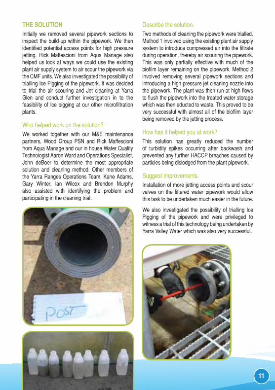
THE SOLUTIONInitially we removed several pipework sections to inspect the build-up within the pipework. We then identified potential access points for high pressure jetting. Rick Maffescioni from Aqua Manage also helped us look at ways we could use the existing plant air supply system to air scour the pipework via the CMF units. We also investigated the possibility of trialling Ice Pigging of the pipework. It was decided to trial the air scouring and Jet cleaning at Yarra Glen and conduct further investigation in to the feasibility of Ice pigging at our other microfiltration plants.
Who helped work on the solution?We worked together with our M&E maintenance partners, Wood Group PSN and Rick Maffescioni from Aqua Manage and our in house Water Quality Technologist Aaron Ward and Operations Specialist, John deBoer to determine the most appropriate solution and cleaning method. Other members of the Yarra Ranges Operations Team, Kane Adams, Gary Winter, Ian Wilcox and Brendon Murphy also assisted with identifying the problem and participating in the cleaning trial.
Describe the solution.Two methods of cleaning the pipework were trialled. Method 1 involved using the existing plant air supply system to introduce compressed air into the filtrate during operation, thereby air scouring the pipework. This was only partially effective with much of the biofilm layer remaining on the pipework. Method 2 involved removing several pipework sections and introducing a high pressure jet cleaning nozzle into the pipework. The plant was then run at high flows to flush the pipework into the treated water storage which was then educted to waste. This proved to be very successful with almost all of the biofilm layer being removed by the jetting process.
How has it helped you at work?This solution has greatly reduced the number of turbidity spikes occurring after backwash and prevented any further HACCP breaches caused by particles being dislodged from the plant pipework.
Suggest improvements.Installation of more jetting access points and scour valves on the filtered water pipework would allow this task to be undertaken much easier in the future.
We also investigated the possibility of trialling Ice Pigging of the pipework and were privileged to witness a trial of this technology being undertaken by Yarra Valley Water which was also very successful.
11
Award Objectives• To create an opportunity which encourages water industry
operational staff to share their in-the-field innovations and/or fixes to problems so that others in the water industry can benefit.
• To provide an application process which is easy to complete and utilises a standard template. This will give all water industry operational staff the same opportunity for presenting their innovation.
• To provide the opportunity for operational staff to receive recognition for their innovation and efforts.
• To encourage operational staff to become aware of and involved with the Water Industry Operators Association of Australia (WIOA).
To allow WIOA to share the good ideas and innovations with other Members through the Operator magazine and/or other publications.
The ProcessThe PASS application template and more details on the Award can be found on the WIOA web site or from the WIOA office.
JudgingAll PASS applications received in the 12 month period ending 1st March annually, will be assessed by an independent panel on a number of criteria, including:
• Commonality of the problem• Benefit to OH&S, water quality, and/or the environment• Financial and sustainability benefits• Application to other industries• Uniqueness, adaptability and simplicity
RewardThe person who submits the PASS application deemed best in that particular year will be announced the winner of the PASS Award at the WIOA NSW Conference. Aqualift Pacific Pty Ltd, as the PASS Award sponsor, will provide sponsorship of $2000 for the winner to join the WIOA team on their annual operational tour of New Zealand including attendance at the NZ WIOG operations conference.
Water Industry Operators Association of Australia PO Box 6012, Shepparton 3632Phone: 03 5821 6744 Fax: 03 5821 6033
www.wioa.org.auWIOA celebrates the sharing of good ideas by publishing all of the 2015 entries for the PASS Award. The authors, WIOA and Aqualift Project Delivery are not responsible for the outcomes of any actions taken on the basis of information in this document, nor for any errors or omissions. The authors, WIOA and Aqualift Project Delivery disclaim all and any liability to any person in respect of anything and the consequences of anything done or omitted to be done by a person in reliance upon the whole or any part of this document. If further expert advice is required the services of a professional should be sought.