Embed Size (px)
Citation preview

Total Length: 730mm (28.7in)
Beam: 180mm (7.09in)
Speed: 60+ km/hr
Motor: Water cooled 2815 out-runner brushless motor (included)
Radio System: 2.4G 2CH Digital Proportional Transmitter (included w/RTR version only)
Speed Control: Water cooled 60A Brushless ESC w/BEC (included)
Drive System: 4mm Flex Shaft Direct Drive
Battery: Two packs of 7.4V 4000mAh 30C+ LiPo Pack (not included)
Specification:Instruction Manual

Safety Precautions• Be very careful to avoid touching the propeller anytime while the model is powered. If your fingers, hands, etc.
come in contact with the spinning propeller, you may be severely injured. This model is capable of inflicting property damage and severe personal injury if a collision occurs. Race your boat responsibly, stay clear of people, full-scale boats and wildlife.
• The metal hardware on your boat can be sharp. Be careful handling the parts.• The brushless motor may become hot. After a run allow the motor to cool before touching it.
Specifications & Description ChangesAll pictures, descriptions, and specifications founded in this instruction manual are subject to changes without notice. Hobbyking maintains no responsibility for inadvertent errors in this manual.
Items Required For Completion & Battery Pack Recommendations
You will need to purchase the following items to operate your H-King Marine brushless motor boat. We highly need to purchase the following items to operate your H-King Marine brushless motor boat.
Battery RecommendationTwo pack of 7.4V 4000mAh 30C+ Lipo battery pack
Charger Recommendation3S LiPo Balance Charger and power supply, or multi-functional intelligent charger (such as Turnigy Accucel 6).
IntroductionThank you for purchasing this H-King Marine brushless racing boat! This manual contains the instructions you need to safely prepare, operate, and maintain your R/C boat. Read over this manual thoroughly before operating the model.
Caution for LiPo battery:
The ESC features a low voltage cut off at 3.2V per cell. When driving your boat, as soon as you notice the boat slow down, that indicates that the ESC low voltage cut-off has initiated. You should immediately drive the boat back to shore slowly. Recharge battery and race again. Don’t keep racing the boat when the ESC low voltage cut-off initiates, otherwise you will allow battery over-discharge, causing damage to the battery pack.

● Water cool 2815 out-runner brushless motor (included) (Pre-installed)● 60A Water cooling Brushless ESC w/BEC (Pre-installed)● Powerful Steering 37g Servo (Pre-installed)● 2.4GHz 2CH Pistol Transmitter (RTR Version only)● Display Boat Stand
HXT4mm Plugs (2pcs)
2 pcs of Allen Key(2.5mm,2mm)
Rudder set
Water proofballoon for RX
Boat Stand
Cable Strap
Three Blade Metal Propeller
Contents of Set
Scottfree Racing
Transmitter
3
60A ESC
Circuit & Cooling System Diagram
RECEIVER
Please use this diagram to connect water cooling system and electronic circuit.
Preparing Your Boat For Operation
Assembling the boat standInsert three ABS pipes into the holes of two boat stands shown as photos, compress boat stands and ABS pipes tightly, then stick EVA to the four corners, this will protect the hull bottom from scratches during construction and storage.

installing the rudder and propellerConcerning the package safety, the rudder and propeller are not pre-installed. They are packed well in the kits bag. Follow the belowing steps to install them by yourself easily.
1. Loosen the screw on the propeller shaft by 7mm Spanner, put the propeller in then retighten the screw.
2. Insert the rudder support into the support which is already installed on the rear of hull. Thread the two pcs of M3 screw in, Apply two pcs of M3 nut on the screws, retighten the screws and nuts by 2.5mm Allen Key and 5.5mm Spanner.
3. Thread the silicone tube in the brass water inlet.
4. Loosen the adjuster on the servo horn so as to push rudder rod to thread in the adjuster located in the rudder horn. Make sure the rudder centered and then Retighten the two adjuster with 2.5mm Allen Key.
Rudder AssemblyNOTE: Please install rudder and support on the right
support which is pre-installed on the rear of hull in factory. Installing rudder and support on the right side is effective for good performance and stability.
1
Installing transmitter batteries (RTR version only)NOTE: The transmitter is not water resistant and should
never come in contact with water.
1. Install four fresh “AA” batteries. Follow the diagram located in the bottom of the battery tray for proper battery orientation.
2. Turn the transmitter “ON”.
4
2.5mm

5
Receiver connection diagram
NOTE: We recommend you 2 packs of 7.4V 4000mAh 30C+ Lipo battery for maximum performance. Using the provided battery straps which are already installed on the battery locators inside the hull to secure the battery. The battery locators help align the batteries for the best running center of gravity for maximum performance. Below are the batteries location inside the hull.
NOTE: There is a water proof rubber ring glued along the slot of hull, always make sure it’s securely positioned before re-install the upper deck.
Scottfree battery locator
Caution: Before racing boat, Please use balloon supplied in tool bag to wrap receiver for water proofing.
Installing the Battery
21
1. Rotate the plastic lock on hatch 90 degrees either to left or right.
2. Lift up and remove the hatch.3. Attach battery connector.
6
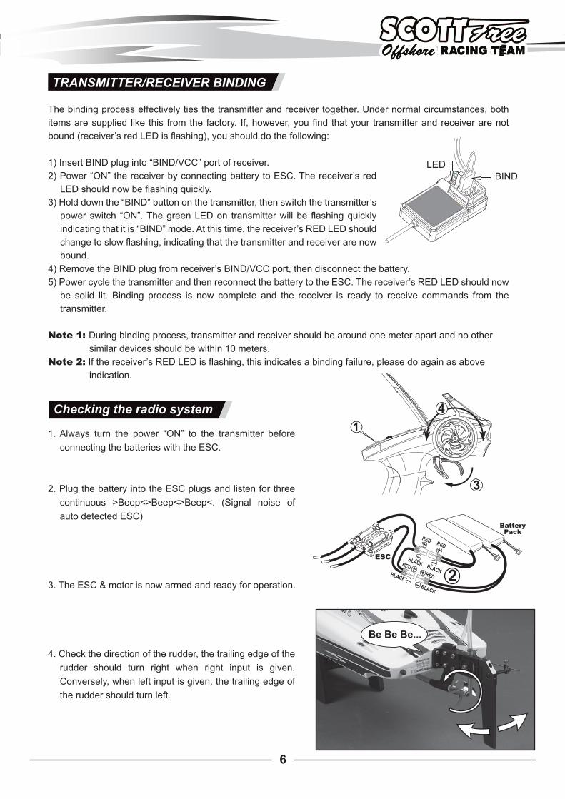
Checking the radio system
1. Always turn the power “ON” to the transmitter before connecting the batteries with the ESC.
2. Plug the battery into the ESC plugs and listen for three continuous >Beep<>Beep<>Beep<. (Signal noise of auto detected ESC)
3. The ESC & motor is now armed and ready for operation.
4. Check the direction of the rudder, the trailing edge of the rudder should turn right when right input is given. Conversely, when left input is given, the trailing edge of the rudder should turn left.
TRANSMITTER/RECEIVER BINDING
The binding process effectively ties the transmitter and receiver together. Under normal circumstances, both items are supplied like this from the factory. If, however, you find that your transmitter and receiver are not bound (receiver’s red LED is flashing), you should do the following:
1) Insert BIND plug into “BIND/VCC” port of receiver.2) Power “ON” the receiver by connecting battery to ESC. The receiver’s red
LED should now be flashing quickly.3) Hold down the “BIND” button on the transmitter, then switch the transmitter’s
power switch “ON”. The green LED on transmitter will be flashing quickly indicating that it is “BIND” mode. At this time, the receiver’s RED LED should change to slow flashing, indicating that the transmitter and receiver are now bound.
4) Remove the BIND plug from receiver’s BIND/VCC port, then disconnect the battery. 5) Power cycle the transmitter and then reconnect the battery to the ESC. The receiver’s RED LED should now
be solid lit. Binding process is now complete and the receiver is ready to receive commands from the transmitter.
Note 1: During binding process, transmitter and receiver should be around one meter apart and no other similar devices should be within 10 meters.
Note 2: If the receiver’s RED LED is flashing, this indicates a binding failure, please do again as above indication.
BIND

7
Transmitter introduction
ST.REV TH.REVBIND
R.LED
ST.TRIM TH.TRIM ST.DR
G.LED
OFF POWER ON
Steering reverse
R LED
Throttle reverse
Bind
G LED
Steering DR
Power
Throttle TRIM
Steering TRIM
ST.REV TH.REVBIND
R.LED
ST.TRIM TH.TRIM ST.DR
G.LED
OFF POWER ON
EPA AdjustmentFunctionUse this when performing left and right steering angle adjustments. End Point Adjustment (EPA) adjusting value range: 0%-100%
Setting1. Steering (right side) angle adjustment Rotate “ST/R” knob to the left end point means minimum value 0%, right end point means maximum value 100%.2. Steering (left side) angle adjustment Rotate “ST/L” knob to the left end point means minimum value 0%, right end point means maximum value 100%.
CAUTION:When adjusting this function, make sure the direction is in agreement with the boat direction, you can adjust by the STEERING “REV-NOR” switch.
ST.REV TH.REVBIND
R.LED
ST.TRIM TH.TRIM ST.DR
G.LED
OFF POWER ON
Trim AdjustmentSteering trimAdjust “ST/TRIM” “R/L” so that rudder is centered prior to operation, you may also adjust this control to make the boat run straight during operation.
CAUTION:When adjusting steering trim, make sure the direction is in agreement with the boat direction, you can adjust by the STEERING “REV-NOR” switch.
Throttle trimAdjust “TH/TRIM” “B/F” to stop propeller from turning while the throttle trigger is in the neutral position.
8
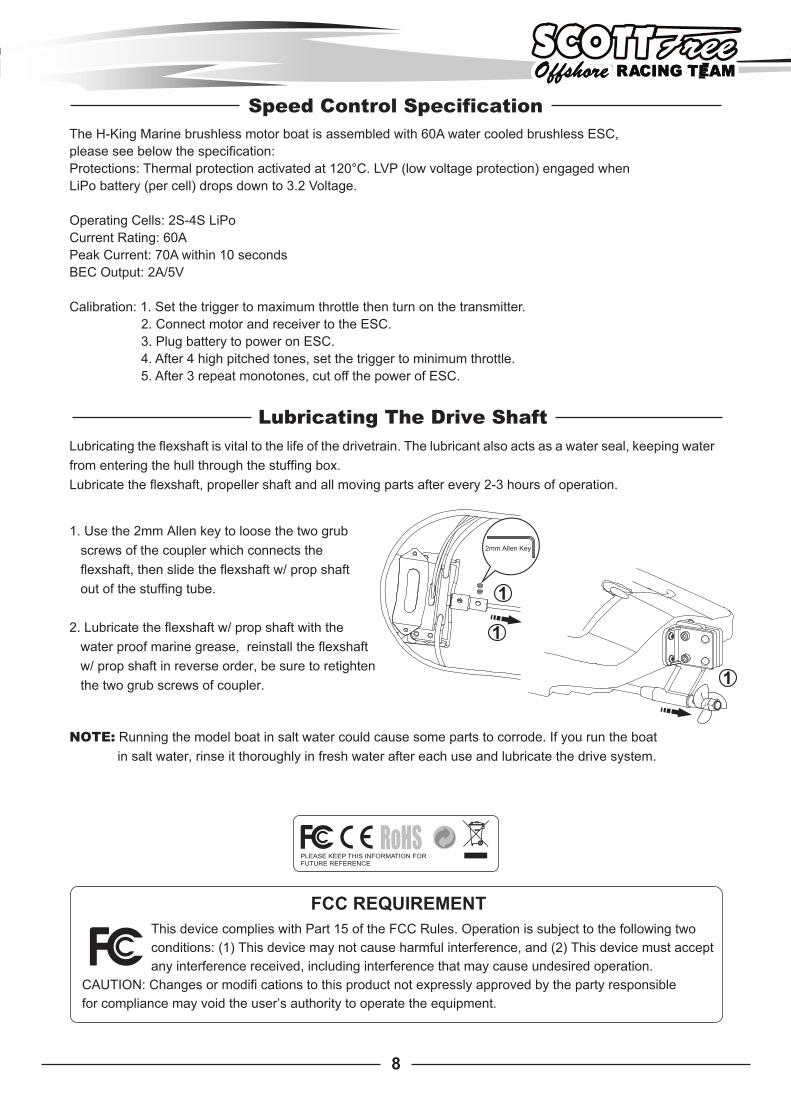
Speed Control SpecificationThe H-King Marine brushless motor boat is assembled with 60A water cooled brushless ESC, please see below the specification:Protections: Thermal protection activated at 120°C. LVP (low voltage protection) engaged whenLiPo battery (per cell) drops down to 3.2 Voltage.
Operating Cells: 2S-4S LiPoCurrent Rating: 60APeak Current: 70A within 10 secondsBEC Output: 2A/5V
Calibration: 1. Set the trigger to maximum throttle then turn on the transmitter. 2. Connect motor and receiver to the ESC. 3. Plug battery to power on ESC. 4. After 4 high pitched tones, set the trigger to minimum throttle. 5. After 3 repeat monotones, cut off the power of ESC.
1. Use the 2mm Allen key to loose the two grub screws of the coupler which connects the flexshaft, then slide the flexshaft w/ prop shaft out of the stuffing tube.
2. Lubricate the flexshaft w/ prop shaft with the water proof marine grease, reinstall the flexshaft w/ prop shaft in reverse order, be sure to retighten the two grub screws of coupler.
NOTE: Running the model boat in salt water could cause some parts to corrode. If you run the boat in salt water, rinse it thoroughly in fresh water after each use and lubricate the drive system.
Lubricating The Drive ShaftLubricating the flexshaft is vital to the life of the drivetrain. The lubricant also acts as a water seal, keeping water from entering the hull through the stuffing box.Lubricate the flexshaft, propeller shaft and all moving parts after every 2-3 hours of operation.
FCC REQUIREMENTThis device complies with Part 15 of the FCC Rules. Operation is subject to the following twoconditions: (1) This device may not cause harmful interference, and (2) This device must acceptany interference received, including interference that may cause undesired operation.
CAUTION: Changes or modifi cations to this product not expressly approved by the party responsiblefor compliance may void the user’s authority to operate the equipment.