Embed Size (px)
Citation preview

THE TRANSCEIVER

Solid Design Basics and HF ExpertiseRaising the Bar
Contesters and DXers are always looking for that competitive edge to magically pull out the weak signal that is either the rare country or multiplier they need to climb up the list. Larger antennas, higher gain pre-amps and other devices in line are great. However, what happens inside the radio with all those signals coming down your feedline can defeat all your efforts. With the design of the IC-7851, Icom’s engineers focused on a new Local Oscillator (LO) that drastically reduces the phase noise. As a result of this design, the purity of the LO achieves a Reciprocal Mixing Dynamic Range (RMDR) of 110dB. In addition to the incredibly clean LO allowing you to hear the weak signals, the new spec-trum scope design enables you to see the weak ones! Faster processors, higher input gain, higher display resolution and a cleaner signal from the receiver’s LO will give you a new window into the RF world. Adding this performance and functionality for both receivers give you a dual scope portal.
THE TRANSCEIVER
1

Competitive Advantage: Reciprocal Mixing Dynamic RangeR e c i p r o c a l M i x i n g D y n a m i c R a n g e
RMDR: 110dB Raising the Bar
IC-7851 IC-7800
IC-7851 IC-7800
Design advances developed by the Icom HF engineers for the Local
Oscillator (LO) enable the IC-7851 to set a new benchmark for amateur
radio receivers. The goal was to dramatically reduce the phase noise
that degrades the target signal due to the sum of the entire signal pres-
ent. The result was a RMDR of 110dB*. Below is a comparison of the
improvement over the IC-7800.
RMDR
RMDR (Reciprocal Mixing Dynamic Range) is the relative level of an
undesired signal, offset “n” kHz from the RX passband, which will raise
noise floor by 3 dB. The local oscillator phase noise will mix with strong
unwanted signals and unavoidably generate noise which masks a
wanted signal.
Breaking the boundaries of traditional designs, the IC-7851 employs a
Direct Digital Synthesizer (DDS) along with a Phase Locked Oscillator for
the LO. The C/N ratio excels beyond the IC-7800 and other similar class
HF transceivers. This design significantly reduces noise components in
both receive and transmit signals.
Improved Phase Noise CharacteristicsPhase noise is coherent in radio circuit design and the new LO design in-
troduced in the IC-7851 makes some major breakthroughs while utilizing
the 64MHz, up-conversion receiver design introduced in the IC-7800.
An impressive 20dB improvement is seen with the IC-7851’s 10 kHz mea-
surement and more than 30dB improvement at a 1 kHz measurement in
comparison to the IC-7800.
Phase Noise Characteristics ComparisonsReceiving Frequency: 14.2 MHz Mode: CW 1st LO frequency: 78.655 MHz
LO C/N Characteristics Comparisons
Crystal Clear LO (Local Oscillator) Design
1.2kHz Optimum Roofing Filter
Optimum Roofing Filter Characteristic Diagram
Optimum Roofing Filter
Despite the trend to switch to a down conversion
or a hybrid conversion receive design, Icom
bel ieves in the so l id per formance of the
up-conversion design. In an up-conversion
receiver, suppression of image interference and
reduce distortion from electric components is
easily overcome. A flat consistent performance
is delivered over a wider frequency range.
The IC-7851 introduces a new 1.2kHz Optimum Roofing Filter, greatly
improving the in-band adjacent signal performance. This newly devel-
oped f i l ter overcomes the gap of a narrower roofing f i l ter in an
up-conversion receiver.
* At a 1kHz offset frequencyReceiving frequency: 14.2 MHz Mode: CW, IF BW: 500 HzRoofing Filter IC-7800 = 3 kHz, IC-7851 = 1.2 kHz
RMDR Comparison
RMDR(dB)
IC-7851
IC-7800
1kHz
110
78
2kHz
116
87
10kHz
121
106
20kHz
124
112
1 kHz 10 kHz 100 kHz 1 MHz100 Hz 10 MHz
-160
-150
-140
-130
-120
-110
-100
-90
-80
Frequency Offset
-70 dBc/Hz -70 dBc/Hz
1 kHz 10 kHz 100 kHz 1 MHz100 Hz 10 MHzFrequency Offset
Receiving Frequency: 14.2 MHz Mode: CW 1st LO frequency: 78.655 MHz
SPAN = 20 kHz, RBW = 30 Hz, VBW = 10 Hz
-160
-150
-140
-130
-120
-110
-100
-90
-80
-10
0
-20
-30
-40
-50
-60
-70
-80
-90
-100
-10
0
-20
-30
-40
-50
-60
-70
-80
-90
-100
2

Twice the Speed, Sensitivity, Resolution and More Control
Scope DSPTMS320C6745 by Texas Instruments32-bit floating point2250 MFLOPS370 MHz clock speed
Mini spectrum scope and audio scope Mini dual spectrum scope and audio scope
Following the design linage of the IC-7800, the IC-7851 uses a dedicated
DSP unit for the Fast Fourier Transform (FFT) spectrum. The 2250
MFLOPS DSP processor enables a new dual scope function and signifi-
cantly faster sweep speeds and better accuracy than in the IC-7800.
S p e c t r u m S c o p e
Improved Spectrum Scope
The waterfall display captures signal strengths over time. This allows
you to see signals that may not be apparent on a normal scope. Addi-
tionally, the combination of the scope attenuator and the wide screen
mode gives you a better view of
weaker signals as band conditions
change. For the u l t imate scope
enhancement, the IC-7851 has a
digital video interface (DVI-I) for a
larger display.
High Resolution Spectrum Waterfall Display
By connecting a human interface device (such as a USB mouse, trackball
or touchpad) to the USB port on the rear panel, you gain control over the
spectrum display pointer for “Click-and-Listen” receiver control. Fix/Center
mode, sweep speed and other settings are controllable.
Click Control
Audio Scope FunctionThe audio scope simultaneously shows an oscilloscope and FFT for receive
and transmit audio. Adjust your transmit audio by watching your compressor
level, equalization and mic gain settings to give you the audio you want for
SSB. The oscilloscope shows the CW waveform. On receive, you can see the
power of your filtering by watching filtering adjustments take out interfering
signals including filter width and notch filter placement. The processing power
in the IC-7851 allows for dual mini band scopes as well as the audio scope.
Span Width
Resolution *1
Sweep Speed
Display Dynamic Range
Noise Floor Level
IC-7851
5kHz–1000kHz
1 pixel minimum *2
29.3 frames/Sec *3
100dB
–30dBμ
IC-7800
5kHz–500kHz
20 pixels minimum *4
4 frames/Sec *3
80dB
–19dBμ
*1 Number of dots shown at the 60 dB level, when receiving a signal.
*2 SPAN = More than 20 kHz, SPEED = Slow
*3 SPAN = Less than 20 kHz, SPEED = Fast
*4 SPAN = 500 kHz, SPEED = Slow
Spectrum scope with waterfall
(wide screen setting)
• Attenuator: 0 dB, –10 dB, –20 dB and –30 dB
• FFT scope with waterfall and FFT scope without waterfall
• Waveform color and drawing (outline or fill) settings
for the FFT scope
• Level: 0dB, –10 dB, –20 dB and –30 dB
• Sample rate: 1ms/Div, 3ms/Div, 10ms/Div, 30ms/Div,
100ms/Div and 300ms/Div, 5 Div width
• Waveform color setting
Dual scope example (Vertically aligned) Dual scope example (Horizontally aligned)
While you can watch both receivers on the scope of the IC-7800, within
the limits of the scope bandwidth, the IC-7851 introduces the new dual
scope – the ability of watching both receivers in separate spectrum
scopes. The dual scope function is vital for watching for multipliers or
band openings in contests, or working all bands/modes on a DXpedition.
Dual Scope Function
Scope Comparison
Specifications for the audio scope Specifications for the oscilloscope
<For example>• Left click to change operating frequency
• Click a button (either left or right) and move right or left side on the screen to increase or decrease the operating frequency (similar to rotating the main dial)
• Right click to temporarily change the receive frequency. Release the mouse button to return.
3

REF 0.0 dBm MKR 14.16 MHzDL −30.0 dBm
10 dB/
0dB
−8.73dBm*A_Write Norm B_Blank Norm
START 0 Hz STOP 30.00 MHz
RBW 300 kHz VBW 300 kHz SWP 200ms ATT 10 dB
MARKER1 4 . 16 MHz
Premium components yield premium performance
The IC-7851 continues the +40dBm, 3rd order
intercept point and 110dB receiver dynamic
range benchmark set by the IC-7800. To
achieve this superb receiver performance, the
entire analog circuitry and components have
been re-engineered to match the DSP units. A
newly designed LO amplifier generates high
output while keeping flat frequency character-
istics over a 60MHz wide range.
BPF unit
Triple DSP Power
Digi-Sel Preselector
The IC-7851 incorporates h igh-grade,
long-term reliable mechanical relays rather
than PIN diodes for switching the Band Pass
Filters (BPF). This deployment of relays re-
moves secondary
distortion products
from the primary
s t a g e o f s i g n a l
processing.
1.2kHzOptimum Roofing Filter3, 6, 15kHz High-Spec 1st IF filters
Automatic Preselector
High Performance OCXO Unit
The IC-7851 uses
t he OC XO (Oven
Control Crystal Oscil-
lator) unit which is
s t a b l e t o w i t h i n
±0.05ppm at 0°C to
50°C. This specifica-
tion means that even on the 50MHz band,
frequency error is less than 2.5Hz! In addition,
a 10MHz reference frequency can be input
and output for accurate tuning.
OCXO unit
PA unit and heat sink
The push-pull power
a m p l i f i e r s u s i n g
power MOS-FETs
wo r k o n 4 8 V D C.
They provide a pow-
erfu l 200W output
power a t fu l l du t y
cycle and low transmit intermodulation. An
effective cooling system maintains internal
tempera tures w i th in a sa fe range and
prevents thermal runaway.
200W Output Power at Full Duty Cycle
Solid Aluminum Main Dial Knob
B a s i c F u n c t i o n s
The main dial tuning
knob is pure func-
t i o n a l b e a u t y .
M a c h i n e d f r o m a
s o l i d a l u m i n u m
block, the main dial
tuning knob gives you a solid operational feel.
The diamond engraved accents are cosmetic
perfection – expected only from a radio of this
caliber.
Dynamic Range (dB)
SpacingRoofingFilter Bandwidth
IC-7851
1kHz
100
99
15kHz
1.2kHz
2kHz
101
105
5kHz
104
111
20 kHz
114
113
Dynamic Range Characteristics
Three separate 24-bit AD/DA converters and
dedicated DSP processors are at the heart of
the IC-7851. With one AD/DA and DSP dedi-
cated to the spectrum scope and two 24-bit
AD/DA and DSP chips for the receivers and
transmit circuits, there is plenty of DSP power
for the most demanding RF environment.
The IC-7851 has multiple AGC loops. The AGC voltages detected in front of and behind the digital IF
filter in the DSP unit. The first AGC loop prevents saturation of the 1st IF amplifier. The other AGC loop
detects the AGC voltage at the digital IF filter output which has only passed the intended signal and
draws the full potential from the
digital IF filter. Combining the
digital IF filter, manual notch,
and the 1st IF stage, these are
all controlled by the DSP unit.
110dB of ultra wide dynamic
range in the receiver means the
IF amplifier is distor tion free
from strong signals.
Dual AGC Loops
Simple receiver system configuration is the
best way to eliminate sources of the spuri-
ous signals and distortion from transceivers.
The IC-7851 uses a double conversion
system composed of a D-MOS FET 1st
mixer and image rejection mixer for the 2nd
stage. The 1st mixer stage is driven with a
signal from the high-drive Local Oscillator
with excel lent C/N. The image reject ion
mixer for the 2nd stage reduces signal dis-
tortion through IF processing and provides
a high-fidelity signal to the DSP unit. This
system provides wide dynamic range, reduc-
ing the distor tion from strong signals and
lower intermodulation.
Image Rejection Mixer
BPF
AGC Loop line
A/D
D/A
AGCDETAGCDETAGCDET
AGCDETAGCDETAGCDET
2nd Mixer (Image Rejection Mixer) Receiver DSP Unit
AMPAMPAMPIF
AMPIF
AMPIF
AMP
IFAMP
IFAMP
IFAMP
IFAMP
IFAMP
IFAMP
90 degreesPhase shifter90 degrees
Phase shifter90 degrees
Phase shifter
Transmit/Receiver DSP (left) andReceiver DSP (right)
ADSP-21489by Analog Devices32-bit floating point DSP 2400 MFLOPS393 MHz clock speed
The preselector
wo rks be tween
1 . 5 M H z a n d
3 0 M H z a n d
rejects distortion
c o m p o n e n t s
d e r i v e d f r o m
out of band interference such as multi-multi
operation or strong broadcast stations. It auto-
matically tracks the intended signal keeping
the preselector’s bandwidth centered on the
operating frequency. The center frequency of
the preselector is manually adjustable from
the DIGI-SEL tuning knob on the front panel.
Intercept Point+40dBm IP3
Dynamic range 110dB
Antenna Terminal input
Re
ce
ive
r o
utp
ut
Noise Floor level
+40dBm IP3 (3rd Order Intercept Point)
BPF Switching: Mechanical Relays
Three high-spec 1st IF “Roofing” filters plus
the new 1.2kHz Optimum Roofing Fil ter
allow only signals within the filter passband
to the 1st IF amplifier stage. You can select
the filter width from 15kHz, 6kHz, 3kHz and
1.2kHz, depending on your operating mode.
(FM mode is fixed at 15kHz)
Four 1st IF “Roofing” Filters
Dynamic Range (typical)
Automatic Preselector bandwidth characteristics
At 14 MHz band
4
RTTY mode display
RTTY, PSK31 as well as the new PSK63
modes are avai lable at your f inger t ips
without the use of a computer. The built-in
Modulator/Demodulators are activated by via
the radio’s functions buttons or an optional
USB keyboard. TX memories make contacts a
snap and communications logs can be stored
on an SD memory card.
SD Memory Card Slot
The DSP controlled RF speech compressor
provides additional punch while maintaining the
original tone quality of the operator. The IC-7851
utilizes the 32-bit DSP for the RF speech com-
pressor, providing the maximum punch without
the fuzzy sound. It’s great for breaking through the
noise and hash to complete the QSO.
Operational functionality for the most advanced operators
Digital RF Speech Compressor
Improved Automatic Antenna Tuner
Save operator profi les,
digi tal voice keyer, CW
memory keyer, RTTY/PSK
logs, IC-7851 “Screen
Shots” and various other
operational settings to your SD Memory card.
The automatic antenna tuner utilizes tune-
setting memories to record the best tuner
configuration for the lowest SWR. This allows
a faster response time when jumping bands or
moving around in the same band.
Filter preset screen
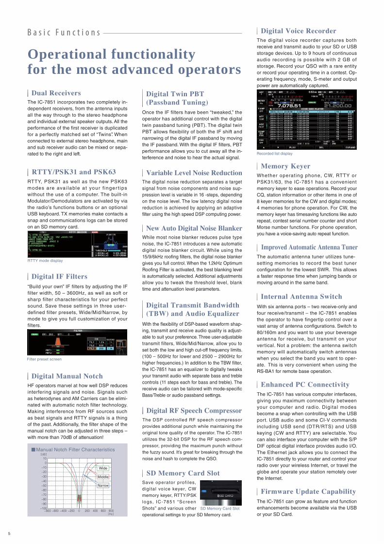
Recorded list display
Digital Voice RecorderThe digital voice recorder captures both
receive and transmit audio to your SD or USB
storage devices. Up to 9 hours of continuous
audio recording is possible with 2 GB of
storage. Record your QSO with a rare entity
or record your operating time in a contest. Op-
erating frequency, mode, S-meter and output
power are automatically captured.
RTTY/PSK31 and PSK63
SD Memory Card Slot
New Auto Digital Noise BlankerWhile most noise blanker reduces pulse type
noise, the IC-7851 introduces a new automatic
digital noise blanker circuit. While using the
15/9/6kHz roofing filters, the digital noise blanker
gives you full control. When the 1.2kHz Optimum
Roofing Filter is activated, the best blanking level
is automatically selected. Additional adjustments
allow you to tweak the threshold level, blank
time and attenuation level parameters.
Variable Level Noise ReductionThe digital noise reduction separates a target
signal from noise components and noise sup-
pression level is variable in 16 -steps, depending
on the noise level. The low latency digital noise
reduction is achieved by applying an adaptive
filter using the high speed DSP computing power.
Firmware Update CapabilityThe IC-7851 can grow as feature and function
enhancements become available via the USB
or your SD Card.
Digital Transmit Bandwidth (TBW) and Audio Equalizer
With the flexibility of DSP-based waveform shap-
ing, transmit and receive audio quality is adjust-
able to suit your preference. Three user-adjustable
transmit filters, Wide/Mid/Narrow, allow you to
set both the low and high cut-off frequency limits.
(100 – 500Hz for lower and 2500 – 2900Hz for
higher frequencies.) In addition to the TBW filter,
the IC-7851 has an equalizer to digitally tweaks
your transmit audio with separate bass and treble
controls (11 steps each for bass and treble). The
receive audio can be tailored with mode-specific
Bass/Treble or audio passband settings.
Digital Twin PBT (Passband Tuning)
Once the IF filters have been “tweaked,” the
operator has additional control with the digital
twin passband tuning (PBT). The digital twin
PBT allows flexibility of both the IF shift and
narrowing of the digital IF passband by moving
the IF passband. With the digital IF filters, PBT
performance allows you to cut away all the in-
terference and noise to hear the actual signal.
Dual ReceiversThe IC-7851 incorporates two completely in-
dependent receivers, from the antenna inputs
all the way through to the stereo headphone
and individual external speaker outputs. All the
performance of the first receiver is duplicated
for a perfectly matched set of “Twins”. When
connected to external stereo headphone, main
and sub receiver audio can be mixed or sepa-
rated to the right and left.
Digital Manual NotchHF operators marvel at how well DSP reduces
interfering signals and noise. Signals such
as heterodynes and AM Carriers can be elimi-
nated with automatic notch filter technology.
Making interference from RF sources such
as beat signals and RTTY signals is a thing
of the past. Additionally, the filter shape of the
manual notch can be adjusted in three steps –
with more than 70dB of attenuation!
Digital IF Filters“Build your own” IF filters by adjusting the IF
filter width, 50 – 3600Hz, as well as soft or
sharp filter characteristics for your perfect
sound. Save these settings in three user-
defined filter presets, Wide/Mid/Narrow, by
mode to give you full customization of your
filters.
Manual Notch Filter Characteristics
B a s i c F u n c t i o n s
Enhanced PC ConnectivityThe IC-7851 has various computer interfaces,
giving you maximum connectivity between
your computer and radio. Digital modes
become a snap when controlling with the USB
port. USB audio and some CI-V commands
including USB send (DTR/RTS) and USB
keying (CW and RTTY) are selectable. You
can also interface your computer with the S/P
DIF optical digital interface provides audio I/O.
The Ethernet jack allows you to connect the
IC-7851 directly to your router and control your
radio over your wireless Internet, or travel the
globe and operate your station remotely over
the Internet.
Internal Antenna Switch With six antenna ports – two receive-only and
four receive/transmit – the IC-7851 enables
the operator to have fingertip control over a
vast array of antenna configurations. Switch to
80/160m and you want to use your beverage
antenna for receive, but transmit on your
vertical. Not a problem: the antenna switch
memory will automatically switch antennas
when you select the band you want to oper-
ate. This is very convenient when using the
RS-BA1 for remote base operation.
Memory KeyerWhether operat ing phone, CW, RTTY or
PSK31/63, the IC-7851 has a convenient
memory keyer to ease operations. Record your
CQ, station information or other items in one of
8 keyer memories for the CW and digital modes;
4 memories for phone operation. For CW, the
memory keyer has timesaving functions like auto
repeat, contest serial number counter and short
Morse number functions. For phone operation,
you have a voice-saving auto repeat function.
Middle
Narrow
Wide
5

Ethernet Connector (LAN)
Other Outstanding Features
[Antenna]
• BNC type RX input/output connectors for
receiver antennas or external attenuators
[Receiver]
• General coverage receiver covers from 30Hz to
60MHz* (* Some frequency ranges are not guaranteed.)
• Two types of preamplifiers:
Preamp 1: improves intermodulation characteristics
Preamp 2: High gain preamp for high bands
• A seven step attenuator (3, 6, 9, 12, 18, 21dB and OFF)
• A dedicated 50MHz band mixer using a Quad FET
• Twin peak filters for better RTTY signal reception
[Transmitter]
• Speech compressor increases average talk
power (SSB mode)
• TX monitor functions
• Fifty sub-audible tones (CTCSS) for repeater
access
• VOX (Voice operated transmission) capability
• All mode power control
Base station
[CW]
• DSP controlled CW keying waveform shaping
• Multi-function electronic keyer with adjustable
keying speed, dot/dash ratio, keyer type, rise time
and paddle polarity
• Electronic keyer speed popup
• CW pitch control from 300 to 900Hz (5Hz pitch)
• CW reverse mode operation for receiving USB
side signal
• Double key jacks for front and rear panels
• Full break-in and semi break-in functions
• CW/AM auto tuning function helps to zero in on
intended signals within ±500Hz range
• Soft and sharp audio filter shapes for the Audio
Peak Filter (APF)
[Operation]
• Set mode functions for flexible and speedy settings
• Memo pads stores up to 10 operating frequencies
and modes
• Quick split function and split lock functions
• Quick Dualwatch function
• SSB/CW synchronous tuning
• RIT and ∂TX variable up to 9.999kHz
• UTC/Local clock and timer function
• 1Hz pitch tuning and display
• 101 memory channels with 10-character channel name
• Built-in voice synthesizer announces the oper-
ating frequency, mode, and S-meter level
• Programmed scan, memory scan, select
memory scan, VSC scan and ∂f scan
• Auto tuning step function
• Dial lock function
• Main dial tension control
• Programmable band edge beeps
• S/P DIF input/output connectors
• BNC type transverter connector
• External speaker connectors for Main/Sub receivers
• FFT scope waveform averaging function for
PSK and RTTY decoder
• Screen saver function
Main Switch
AC Power Cord Receptacle
S/P DIF In/Out Jacks
USB Connector (Type-A)
External Display Connector (DVI-I)
Breaker Switch
Ground Terminal
ALC Level Pot
Antenna Connectors
Reference Frequency In/Out Jack
Receive Antenna Connectors B
Transverter Jack
Receive Antenna Connectors A
CI-V Remote Control Jack
S-meter OutputJack
External Keypad Jack
KeyJack
ALC Input Jack
TX/RX Control Jack
(Relay)
ACC Socket B ACC Socket A
USB Connector(Type-B)
External DCOutput Jack
External Speaker Jacks
• Most functions of your transceiver, including interference rejection
functions and IF filter settings, can be controlled.
• The spectrum scope with the waterfall function can be observed.
• Received voice recording function.
• Optional RC-28 USB remote encoder provides a hardware dial/transmit
functions for a realistic dial operation.
• The IC-7851 can wake-up from the standby mode through the RS-BA1 software.
IP Network
PC (Remote station)Windows® PC
Remote base operation is made easy as the IC-7851 operating system in-
corporates the remote base server software. A computer is not required in
the shack for audio or rig control. Up to three, unique user log-in/password
configurations are part of the internal server. As the rig control has a prior-
ity of service, the controls will feel like you are right in front of your rig.
Simplified Remote Control (Optional RS-BA1)
Optional RS-BA1 main features
6

SPECIFICATIONS
TRANSMITTER
RECEIVER
ANTENNA TUNER
GENERAL
Mode
No. of memory channels
Antenna connector
Operating temp. range
Frequency stability
Frequency resolution
Power supply requirement
Current drain
Dimensions (W×H×D,
projections not included)
Weight (approximate)
Receive system
Intermediate frequencies
Sensitivity (typical)
Squelch sensitivity
Selectivity
Spurious and image
rejection ratio
Audio output power
RIT variable range
Output power
Modulation system
Spurious emissions
Carrier suppression
Unwanted sideband
suppression
∂TX variable range
Microphone impedance
Matching impedance
range
Minimum operating
power
Tuning accuracy
Insertion loss
USB, LSB, CW, RTTY, PSK31/63, AM, FM
101 (99 regular, 2 scan edges)
SO-239×4 and BNC×2 (50Ω unbalanced (Tuner off))
0°C to +50°C; +32°F to +122°F
Less than ±0.05ppm (0°C to +50°C @ 54MHz, after warm up)
1Hz (minimum)
85–265V AC
TX: 800VA (Max. power)
RX: 130VA/120VA typ. (Max. audio/standby)
425×149×435 mm; 16.73×5.87×17.13 in
23.5 kg; 51.8 lb
Double conversion super-heterodyne system
Main receiver: 64.455MHz/36kHz (1st/2nd)
Sub receiver: 64.555MHz/36kHz (1st/2nd)
(HF: Pre-amp 1 ON, 50MHz: Pre-amp 2 ON)
SSB, CW, RTTY, PSK: Less than 5.6μV (Pre-amp: OFF)
FM: Less than 1μV (Pre-amp: OFF)
More than 70dB
More than 2.6W (10% distortion, 8Ω load)
±9.999kHz
SSB/CW/FM/RTTY/PSK: 5–200W
AM: 5–50W
Transverter connector (CW): More than –20dBm
SSB : Digital P.S.N. modulation
AM : Digital low power modulation
FM : Digital phase modulation
HF bands: More than 60dB
50MHz band: More than 70dB
More than 63dB
More than 70dB
±9.999kHz
600Ω (8-pin connector)
HF bands: 16.7Ω to 150Ω unbalanced (VSWR better than 3:1)
50MHz: 20Ω to 125Ω unbalanced (VSWR better than 2.5:1)
HF bands: 8W
50MHz band: 15W
VSWR 1.5:1 or less
Less than 1.0 dB (after tuning)
(Unit: MHz)
Receiver
Transmit0.1357–0.1378
10.100–10.150
24.890–24.990
1.810–1.999
14.000–14.350
28.000–29.700
3.500–3.800
18.068–18.168
50.000–52.000
7.000–7.200
21.000–21.450
All stated specifications are subject to change without notice or obligation.
OPTIONS Some options may not be available in some countries. Please ask your dealer for details.
HM-36 HAND MICROPHONE SP-33 EXTERNAL SPEAKER
Wooden box speaker.
SM-30 DESKTOP MICROPHONE CT-17 CI-V LEVEL
CONVERTER
RS-BA1 IP REMOTE
CONTROL SOFTWARE Windows® based software
RC-28 USB REMOTE ENCODERFor use with RS-BA1
THE TRANSCEIVER
Frequency coverage*1
0.030–60.000*2
*1 Showing EUR version. Varies according to version. *2 Some frequency bands are not guaranteed. SSB, CW, RTTY, PSK(BW=2.4kHz, at 10dB S/N)
AM (BW=6kHz, at 10dB S/N)
FM (BW=15kHz, at 12dB
SINAD)
SSB (BW=2.4kHz, sharp)
CW/RTTY/PSK (BW=500Hz, sharp)
AM (BW=6kHz)
FM (BW=15kHz)
0.1–1.799MHz
0.5μV
6.3μV
–
More than
2.4kHz/–3dB
500Hz/–3dB
6.0kHz/–3dB
12.0kHz/–6dB
Less than
3.6kHz/–60dB
700Hz/–60dB
15.0kHz/–60dB
20.0kHz/–60dB
1.8–29.990MHz
0.16μV
2μV
0.5μV(28–29.9MHz)
50–54MHz
0.13μV
1μV
0.32μV
SM-50 DESKTOP
MICROPHONEIC-PW1/IC-PW1EURO
HF+50MHz 1kW LINEAR AMPLIFIER
SP-34 EXTERNAL SPEAKER
Automatic antenna tuner and compact detach
able controller are standard. 2 exciter inputs and
4 antenna connectors are available.
4 audio filters; headphone jack; can
connect to 2 transceivers.
Input impedance: 8Ω Max. input: 5WDynamic microphone with
[UP/DOWN] switches.
Supplied accessories: (* May differs depending on version) • Rack mount handles • SD card • AC power cable • Spare fuses • Plugs
Icom, Icom Inc. and Icom logo are registered trademarks of Icom Incorporated (Japan) in Japan, the United States, the United Kingdom, Germany,
France, Spain, Russia, Australia, New Zealand, and/or other countries. Windows is either registered trademark or trademark of Microsoft
Corporation in the United States and/or other countries. All other trademarks are the properties of their respective holders.
15HS0110* © 2015 Icom Inc.
12421 Willows Road NE,Kirkland, WA 98034, U.S.A.Phone: +1 (425) 454-8155Fax: +1 (425) 454-1509E-mail: [email protected]: http://www.icomamerica.com
Unit 1 / 103 Garden Road,Clayton, VIC 3168 AustraliaPhone: +61 (03) 9549 7500Fax: +61 (03) 9549 7505 E-mail: [email protected]: http://www.icom.net.au
Blacksole House, Altira Park, Herne Bay, Kent, CT6 6GZ, U.K.Phone: +44 (0) 1227 741741Fax: +44 (0) 1227 741742E-mail: [email protected]: http://www.icomuk.co.uk
Zac de la Plaine, 1 Rue Brindejonc des Moulinais, BP 45804, 31505 Toulouse Cedex 5, FrancePhone: +33 (5) 61 36 03 03Fax: +33 (5) 61 36 03 00E-mail: [email protected]: http://www.icom-france.com
Ctra. Rubi, No. 88 "Edificio Can Castanyer" Bajos A 08174, Sant Cugat del Valles, Barcelona, SpainPhone: +34 (93) 590 26 70Fax: +34 (93) 589 04 46E-mail: [email protected]: http://www.icomspain.com
Glenwood Centre #150-6165 Highway 17A, Delta, B.C., V4K 5B8, CanadaPhone: +1 (604) 952-4266Fax: +1 (604) 952-0090E-mail: [email protected]: http://www.icomcanada.com
6F No. 68, Sec. 1 Cheng-Teh Road, Taipei, Taiwan, R.O.C.Phone: +886 (02) 2559 1899Fax: +886 (02) 2559 1874E-mail: [email protected]: http://www.asia-icom.com
No.101, Building 9, Caifuxingyuan Park, No.188 Maoting Road, Chedun Town, Songjiang District, Shanghai, 201611, ChinaPhone: +86 (021) 6153 2768Fax: +86 (021) 5765 9987E-mail: [email protected]: http://www.bjicom.com
Rua Itororó, 444 Padre EustáquioBelo Horizonte MG, CEP: 30720-450, BrazilPhone: +55 (31) 3582 8847Fax: +55 (31) 3582 8987E-mail: [email protected]
39C Rennie Drive, Airport Oaks,Auckland, New ZealandPhone: +64 (09) 274 4062Fax: +64 (09) 274 4708E-mail: [email protected]: http://www.icom.co.nz
Communication EquipmentAuf der Krautweide 2465812 Bad Soden am Taunus, GermanyPhone: +49 (6196) 76685-0Fax: +49 (6196) 76685-50E-mail: [email protected]: http://www.icomeurope.com
Printed in Japan
Your local distributor/dealer:
Count on us!www.icom.co.jp/world1-1-32, Kami-minami, Hirano-Ku, Osaka 547-0003, Japan Phone: +81 (06) 6793 5302 Fax: +81 (06) 6793 0013