Embed Size (px)
Citation preview
8/6/2019 2014 f1 Technical Regulations - Published on 20.07
http://slidepdf.com/reader/full/2014-f1-technical-regulations-published-on-2007 1/77
2014 FORMULA ONE TECHNICAL REGULATIONS
SUMMARY
ARTICLE 1 : DEFINITIONS1.1 Formula One Car1.2 Automobile1.3 Land Vehicle1.4 Bodywork1.5 Wheel1.6 Complete wheel1.7 Automobile Make1.8 Event1.9 Weight1.10 Cubic capacity1.11 Pressure charging1.12 Cockpit1.13 Sprung suspension1.14 Survival cell1.15 Camera1.16 Camera housing1.17 Cockpit padding1.18 Brake caliper1.19 Electronically controlled1.20 Open and closed sections1.21 Power train1.22 Power unit1.23 Engine1.24 Energy Recovery System (ERS)1.25 Motor Generator Unit - Kinetic (MGUK)1.26 Motor Generator Unit - Heat (MGUH)1.27 Energy Store (ES)
ARTICLE 2 : GENERAL PRINCIPLES2.1 Role of the FIA
8/6/2019 2014 f1 Technical Regulations - Published on 20.07
http://slidepdf.com/reader/full/2014-f1-technical-regulations-published-on-2007 2/77
3.5 Width behind the rear wheel centre line
3.6 Overall height3.7 Front bodywork3.8 Bodywork in front of the rear wheels3.9 Bodywork between the rear wheels3.10 Bodywork behind the rear wheel centre line3.11 Bodywork around the front wheels3.12 Bodywork facing the ground3.13 Skid block
3.14 Overhangs3.15 Aerodynamic influence3.16 Upper bodywork3.17 Bodywork flexibility3.18 Driver adjustable bodyworkARTICLE 4 : WEIGHT4.1 Minimum weight4.2 Ballast4.3 Adding during the raceARTICLE 5 :POWER UNIT 5.1 Engine specification5.2 Other means of propulsion and energy recovery 5.3 Power unit dimensions5.4 Weight and centre of gravity5.5 Torque control 5.6 Exhaust systems5.7 Variable geometry systems5.8 Fuel systems5.9 Ignition systems5.10 Energy Recovery System 5.11 Engine ancillaries (coolant, lubricant and scavenge pumps) 5.12 Engine intake air5.13 Materials and construction - Definitions5.14 Materials and construction – General5.15 Materials and construction – Components5.16 Materials and construction – Pressure charging and exhaust systems5.17 Materials and construction – Energy recovery and storage systems5.18 Starting the engine5.19 Electric mode 5 20 Stall prevention systems
8/6/2019 2014 f1 Technical Regulations - Published on 20.07
http://slidepdf.com/reader/full/2014-f1-technical-regulations-published-on-2007 3/77
ARTICLE 7 : OIL AND COOLANT SYSTEMSAND CHARGE AIR COOLING
7.1 Location of oil tanks7.2 Longitudinal location of oil system7.3 Catch tank7.4 Transversal location of oil system7.5 Coolant header tank7.6 Cooling systems7.7 Oil and coolant lines
ARTICLE 8 : ELECTRICAL SYSTEMS8.1 Software and electronics inspection8.2 Control electronics8.3 Start systems8.4 Data acquisition8.5 Telemetry8.6 Driver controls and displays8.7 Driver radio8.8 Accident data recorders (ADR)8.9 Track signal information display8.10 Medical warning system8.11 Installation of electrical systems or components
ARTICLE 9 : TRANSMISSION SYSTEM9.1 Transmission types9.2 Clutch control9.3 Traction control9.4 Clutch disengagement9.5 Gearboxes9.6 Gear ratios9.7 Reverse gear9.8 Torque transfer systems
ARTICLE 10 : SUSPENSION AND STEERING SYSTEMS10.1 Sprung suspension10.2 Suspension geometry
10.3 Suspension members10.4 Steering10.5 Suspension uprights
ARTICLE 11 : BRAKE SYSTEM11.1 Brake circuits and pressure distribution11.2 Brake calipers
8/6/2019 2014 f1 Technical Regulations - Published on 20.07
http://slidepdf.com/reader/full/2014-f1-technical-regulations-published-on-2007 4/77
12.6 Specification of tyres
12.7 Tyre gases12.8 Wheel assembly
ARTICLE 13 : COCKPIT13.1 Cockpit opening13.2 Steering wheel13.3 Internal cross section13.4 Position of the driver’s feet
ARTICLE 14 : SAFETY EQUIPMENT14.1 Fire extinguishers14.2 Master switch14.3 Rear view mirrors14.4 Safety belts14.5 Rear light14.6 Cockpit padding14.7 Wheel retention14.8 Seat fixing and removal14.9 Head and neck supports
ARTICLE 15 : CAR CONSTRUCTION15.1 Permitted materials15.2 Roll structures15.3 Structure behind the driver15.4 Survival cell specifications15.5 Survival cell safety requirements
ARTICLE 16 : IMPACT TESTING16.1 Conditions applicable to all impact tests16.2 Frontal test 116.3 Frontal test 216.4 Side test16.5 Rear test16.6 Steering column test
ARTICLE 17 : ROLL STRUCTURE TESTING17.1 Conditions applicable to both roll structure tests17.2 Principal roll structure test17.3 Second roll structure test
ARTICLE 18 : STATIC LOAD TESTING18.1 Conditions applicable to all static load tests
8/6/2019 2014 f1 Technical Regulations - Published on 20.07
http://slidepdf.com/reader/full/2014-f1-technical-regulations-published-on-2007 5/77
19.3 Properties
19.4 Composition of the fuel19.5 Air19.6 Safety19.7 Fuel approval19.8 Sampling and testing at an Event
ARTICLE 20 : TELEVISION CAMERAS AND TIMING TRANSPONDERS20.1 Presence of cameras and camera housings20.2 Location of camera housings20.3 Location and fitting of camera and equipment20.4 Transponders20.5 Installation
ARTICLE 21 : FINAL TEXT
8/6/2019 2014 f1 Technical Regulations - Published on 20.07
http://slidepdf.com/reader/full/2014-f1-technical-regulations-published-on-2007 6/77
8/6/2019 2014 f1 Technical Regulations - Published on 20.07
http://slidepdf.com/reader/full/2014-f1-technical-regulations-published-on-2007 7/77
1.12 Cockpit :
The volume which accommodates the driver.
1.13 Sprung suspension :
The means whereby all complete wheels are suspended from the body/chassis unit by a springmedium.
1.14 Survival cell :
A continuous closed structure containing the fuel tank and the cockpit.
1.15 Camera :Television cameras the dimensions of which are defined in Drawing 6.
1.16 Camera housing :
A device which is identical in shape and weight to a camera and which is supplied by therelevant competitor for fitting to his car in lieu of a camera.
1.17 Cockpit padding :
Non-structural parts placed within the cockpit for the sole purpose of improving driver comfortand safety. All such material must be quickly removable without the use of tools.
1.18 Brake caliper :
All parts of the braking system outside the survival cell, other than brake discs, brake pads,caliper pistons, brake hoses and fittings, which are stressed when subjected to the brakingpressure. Bolts or studs which are used for attachment are not considered to be part of thebraking system.
1.19 Electronically controlled :Any command system or process that utilises semi-conductor or thermionic technology.
1.20 Open and closed sections :A section will be considered closed if it is fully complete within the dimensioned boundary towhich it is referenced, if it is not it will be considered open.
1.21 Power train :
The power unit and associated torque transmission systems, up to but not including the drive
shafts.1.22 Power unit :
The internal combustion engine, complete with its ancillaries, any energy recovery system andall actuation systems necessary to make them function at all times.
1.23 Engine
8/6/2019 2014 f1 Technical Regulations - Published on 20.07
http://slidepdf.com/reader/full/2014-f1-technical-regulations-published-on-2007 8/77
1.26 Motor Generator Unit - Heat (MGUH) :
The Heat Motor Generator Unit is the electrical machine linked to the exhaust turbine of apressure charging system as part of the ERS.
1.27 Energy Store (ES) :
The part of ERS that stores energy, including its safety control electronics and a minimalhousing.
8/6/2019 2014 f1 Technical Regulations - Published on 20.07
http://slidepdf.com/reader/full/2014-f1-technical-regulations-published-on-2007 9/77
ARTICLE 2 : GENERAL PRINCIPLES
2.1 Role of the FIA : The following technical regulations for Formula One cars are issued by the FIA.
2.2 Amendments to the regulations :
Changes to these regulations may only be made in accordance with the provisions of the 2009Concorde Agreement.
2.3 Dangerous construction :
The stewards of the meeting may exclude a vehicle whose construction is deemed to bedangerous.
2.4 Compliance with the regulations :
Automobiles must comply with these regulations in their entirety at all times during an Event.
Should a competitor introduce a new design or system or feel that any aspect of theseregulations is unclear, clarification may be sought from the FIA Formula One TechnicalDepartment. If clarification relates to any new design or system, correspondence must include:
- A full description of the design or system.
- Drawings or schematics where appropriate.
- The competitor's opinion concerning the immediate implications on other parts of thecar of any proposed new design.
- The competitor's opinion concerning any possible long term consequences or newdevelopments which may come from using any such new designs or systems.
- The precise way or ways in which the competitor feels the new design or system willenhance the performance of the car.
2.5 New systems or technologies :
Any new system, procedure or technology not specifically covered by these regulations, butwhich is deemed permissible by the FIA Formula One Technical Department, will only beadmitted until the end of the Championship during which it is introduced. Following this theFormula One Commission will be asked to review the technology concerned and, if they feel itadds no value to Formula One in general, it will be specifically prohibited.
Any team whose technology is prohibited in this way will then be required to publish full
technical details of the relevant system or procedure. 2.6 Measurements :
All measurements must be made while the car is stationary on a flat horizontal surface.
2.7 Duty of Competitor :
It is the duty of each competitor to satisfy the FIA technical delegate and the stewards of the
8/6/2019 2014 f1 Technical Regulations - Published on 20.07
http://slidepdf.com/reader/full/2014-f1-technical-regulations-published-on-2007 10/77
ARTICLE 3 : BODYWORK AND DIMENSIONS
One of the purposes of the regulations under Article 3 below is to minimize the detrimental effectthat the wake of a car may have on a following car.
Furthermore, infinite precision can be assumed on certain dimensions provided it is clear that suchan assumption is not being made in order to circumvent or subvert the intention of the relevantregulation.
For illustrations refer to drawings 1A-17A in the Appendix to these regulations.
3.1 Wheel centre line :
The centre line of any wheel shall be deemed to be half way between two straight edges,perpendicular to the surface on which the car is standing, placed against opposite sides of thecomplete wheel at the centre of the tyre tread.
3.2 Height measurements :
All height measurements will be taken normal to and from the reference plane.
3.3 Overall width :
The overall width of the car, excluding tyres, must not exceed 1800mm with the steeredwheels in the straight ahead position.
3.4 Width ahead of the rear wheel centre line :
3.4.1 Bodywork width between the front and the rear wheel centre lines must not exceed 1400mm.
Bodywork width ahead of the front wheel centre line must not exceed 1650mm.
3.4.2 In order to prevent tyre damage to other cars, any bodywork outboard of the most inboardpart of the bodywork used to define the area required by Article 3.7.5, and which is more than450mm ahead of the front wheel centre line, must be at least 10mm thick (being the minimumdistance when measured normal to the surface in any direction) with a 5mm radius applied toall extremities.
3.4.3 In order to avoid the spread of debris on the track following an accident, the outer skins of thefront wing endplates and any turning vanes in the vicinity of the front wheels (and any similarlyvulnerable bodywork parts in this area), must be made predominantly from materials whichare included for the specific purpose of containing debris.
The FIA must be satisfied that all such parts are constructed in order to achieve the statedobjective.
3.5 Width behind the rear wheel centre line :
3.5.1 The width of bodywork behind the rear wheel centre line and less than 150mm above thereference plane must not exceed 1000mm.
3 5 2 The width of bodywork behind the rear wheel centre line and more than 150mm above the
8/6/2019 2014 f1 Technical Regulations - Published on 20.07
http://slidepdf.com/reader/full/2014-f1-technical-regulations-published-on-2007 11/77
3.7.2 Any horizontal section taken through bodywork located forward of a point lying 450mm
forward of the front wheel centre line, less than 250mm from the car centre line, and between125mm and 200mm above the reference plane, may only contain two closed symmetricalsections with a maximum total area of 5000mm 2. The thickness of each section may notexceed 25mm when measured perpendicular to the car centre line.
Once fully defined, the sections at 125mm above the reference plane must be projectedvertically to join the profile required by Article 3.7.3. A radius no greater than 10mm may beused where these sections join.
3.7.3 Forward of a point lying 450mm ahead of the front wheel centre line and less than 250mm
from the car centre line and less than 125mm above the reference plane, only one singlesection may be contained within any longitudinal vertical cross section parallel to the carcentre line. Furthermore, with the exception of local changes of section where the bodyworkdefined in Article 3.7.2 attaches to this section, the profile, incidence and position of thissection must conform to Drawing 7.
3.7.4 In the area bounded by lines between 450mm and 1000mm ahead of the front wheel centreline, 250mm and 400mm from the car centre line and between 75mm and 275mm above thereference plane, the projected area of all bodywork onto the longitudinal centre plane of the
car must be no more than 20,000mm2
.3.7.5 Ahead of the front wheel centre line and between 750mm and 825mm from the car centre line
there must be bodywork with a projected area of no less than 95,000mm 2 in side view. Anyintersection of this bodywork with a lateral vertical plane or a horizontal plane must form onecontinuous line.
3.7.6 Only a single section, which must be open, may be contained within any longitudinal verticalcross section taken parallel to the car centre line forward of a point 150mm ahead of the frontwheel centre line, less than 250mm from the car centre line and more than 125mm above thereference plane.
Any cameras or camera housings approved by the FIA in addition to a single inlet aperture forthe purpose of driver cooling (such aperture having a maximum projected surface area of 1500mm 2 and being situated forward of the section referred to in Article 15.4.3) will be exemptfrom the above.
3.7.7 No bodywork situated more than 1950mm forward of rear face of the cockpit entry templatemay be more than 550mm above the reference plane.
3.8 Bodywork in front of the rear wheels :
3.8.1 Other than the rear view mirrors (including their mountings), each with a maximum area of 12000mm² and 14000 mm 2 when viewed from directly above or directly from the siderespectively, no bodywork situated more than 330mm behind the front wheel centre line andmore than 330mm forward of the rear wheel centre line, which is more than 600mm above
8/6/2019 2014 f1 Technical Regulations - Published on 20.07
http://slidepdf.com/reader/full/2014-f1-technical-regulations-published-on-2007 12/77
a) The volume between 50mm forward of the rear wheel centre line and 300mm rearward
of the rear face of the cockpit entry template, which is more than 25mm from the carcentre line and more than 100mm above the reference plane.
b) The volume between 300mm rearward of the rear face of the cockpit entry templateand the rear face of the cockpit entry template, which is more than 125mm from the carcentre line and more than 100mm above the reference plane.
c) The volume between the rear face of the cockpit entry template and 450mm forward of the rear face of the cockpit entry template, which is more than 350mm from the carcentre line and more than 100mm above the reference plane.
d) The volume between the rear face of the cockpit entry template and 450mm forward of the rear face of the cockpit entry template, which is more than 125mm from the carcentre line and more than 675mm above the reference plane.
The surfaces lying within these volumes, which are situated more than 55mm forward of therear wheel centre line, must not contain any apertures (other than those permitted by Article3.8.5) or contain any vertical surfaces which lie normal to the car centre line.
3.8.5 Once the relevant bodywork surfaces are defined in accordance with Article 3.8.4, apertures,
any of which may adjoin or overlap each other, may be added for the following purposes only:- Single apertures either side of the car centre line for the purpose of exhaust exits. These
apertures may have a combined area of no more than 50,000mm 2 when projected ontothe surface itself. No point on an aperture may be more than 350mm from any otherpoint on the aperture.
- Apertures either side of the car centre line for the purpose of allowing suspensionmembers and driveshafts to protrude through the bodywork. Only one aperture may beadded for each suspension member and no such aperture may have an area greaterthan 12,000 mm 2 when projected onto the surface itself. No point on an aperture maybe more than 200mm from any other point on the aperture.
3.8.6 The impact absorbing structures defined by Article 15.5.2 must be fully enclosed by bodywork,such that no part of the impact structure is in contact with the external air flow. When cut by alongitudinal vertical plane, the bodywork enclosing these impact structures must not formclosed sections in the region between 450mm and 875mm forward of the rear edge of thecockpit template.
3.8.7 With the exception of a transparent windscreen, antenna or pitot tubes, no bodywork higherthan the top of the front roll structure will be permitted forward of it.
3.9 Bodywork between the rear wheels :
3.9.1 No bodywork situated between 50mm and 330mm forward of the rear wheel centre line maybe more than 730mm above the reference plane.
3 9 2 No bodywork situated between 50mm forward of the rear wheel centre line and 150mm
8/6/2019 2014 f1 Technical Regulations - Published on 20.07
http://slidepdf.com/reader/full/2014-f1-technical-regulations-published-on-2007 13/77
With the exception of minimal parts solely associated with adjustment of the section in
accordance with Article 3.18 :- When viewed from the side of the car, no longitudinal cross section may have more than
two sections in this area, each of which must be closed.
- No part of these longitudinal cross sections in contact with the external air stream mayhave a local concave radius of curvature smaller than 100mm.
Once the rearmost and uppermost section is defined, ‘gurney’ type trim tabs may be fitted tothe trailing edge. When measured in any longitudinal cross section no dimension of any suchtrim tab may exceed 20mm.The chord of the rearmost and uppermost closed section must always be smaller than thechord of the lowermost section at the same lateral station.
Furthermore, the distance between adjacent sections at any longitudinal plane must liebetween 10mm and 15mm at their closest position, except, in accordance with Article 3.18,when this distance must lie between 10mm and 50mm.
3.10.3 In order to ensure that the individual profiles and the relationship between these two sections
can only change whilst the car is in motion in accordance with Article 3.18, they must bebridged by means of pairs of rigid impervious supports arranged such that no part of thetrailing edge of the forward section may be more than 200mm laterally from a pair of supports.These pairs of supports must :
- Be located no more than 355mm from the car centre line.
- Fully enclose each complete section such that their inner profiles match that of eachsection. With the exception of minimal local changes where the two sections areadjacent to each other, their outer profiles must be offset from the inner profiles bybetween 8mm and 30mm and may not incorporate any radius smaller than 10mm(‘gurney’ type trim tabs may however be fitted between the supports).
- Be aligned as a pair so as to provide a bearing across their full thickness and along aprofile length of at least 10mm when the distance between the two sections is at itsclosest position.
- Not be recessed into the wing profiles (where a recess is defined as a reduction insection at a rate greater than 45° with respect to a lateral axis).
- Be arranged so that any curvature occurs only in a horizontal plane.- Be between 2mm and 5mm thick.
- Be rigidly fixed to their respective sections.
- Be constructed from a material with modulus greater than 50GPa.
Th ill b i d h i h h h i i li i h A i l
8/6/2019 2014 f1 Technical Regulations - Published on 20.07
http://slidepdf.com/reader/full/2014-f1-technical-regulations-published-on-2007 14/77
3.10.7 No part of the car more than 375mm from the car centre line may be more than 350mm
behind the rear wheel centre line.3.10.8 In side view, the projected area of any bodywork lying between 300mm and 950mm above the
reference plane and between the rear wheel centre line and a point 600mm behind it andmore than 355mm from the car centre line must be greater than 330000mm².
3.10.9 Any horizontal section between 600mm and 750mm above the reference plane, taken throughbodywork located rearward of a point lying 50mm forward of the rear wheel centre line andless than 75mm from the car centre line, may contain no more than two closed symmetricalsections with a maximum total area of 5000mm 2. The thickness of each section may not
exceed 25mm when measured perpendicular to the car centre line.Once fully defined, the section at 745mm above the reference plane may be extruded upwardsto join the sections defined in Article 3.10.2. A fillet radius no greater than 10mm may be usedwhere these sections join.
3.11 Bodywork around the front wheels :
3.11.1 With the exception of the air ducts described in Article 11.4 and the mirrors described inArticle 3.8.1, in plan view, there must be no bodywork in the area formed by the intersection
of the following lines :- A longitudinal line parallel to and 900mm from the car centre line.
- A transverse line 450mm forward of the front wheel centre line.
- A diagonal line from 450mm forward of the front wheel centre line and 400mm from thecar centre line to 750mm forward of the front wheel centre line and 250mm from thecar centre line.
- A transverse line 750mm forward of the front wheel centre line.
- A longitudinal line parallel to and 165mm from the car centre line.
- A diagonal line running forwards and inwards, from a point 875mm forward of the rearface of the cockpit entry template and 240mm from the car centre line, at an angle of 4.5° to the car centre line.
- A diagonal line from 875mm forward of the rear face of the cockpit entry template and240mm from the car centre line to 625mm forward of the rear face of the cockpit entrytemplate and 415mm from the car centre line.
- A transverse line 625mm forward of the rear face of the cockpit entry template.
For reference this area is shown in Drawing 17A in the Appendix to these regulations.
3.11.2 With the exception of the air ducts described in Article 11.4, in side view, there must be nobodywork in the area formed by two vertical lines, one 325mm behind the front wheel centreline, one 450mm ahead of the front wheel centre line, one diagonal line intersecting the
8/6/2019 2014 f1 Technical Regulations - Published on 20.07
http://slidepdf.com/reader/full/2014-f1-technical-regulations-published-on-2007 15/77
The step plane must be 50mm above the reference plane.
3.12.2 Additionally, the surface formed by all parts lying on the reference plane must :- Cover the area which is bounded by two transversal lines, one 330mm behind the front
wheel centre line and the other on the rear wheel centre line, and two longitudinal lines150mm either side of the car centre line.
- Have a maximum width of 500mm.
- Be symmetrical about the car centre line.
- Have a 50mm radius (+/-2mm) on each front corner when viewed from directly beneaththe car, this being applied after the surface has been defined.
3.12.3 The surface lying on the reference plane must be joined around its periphery to the surfaceslying on the step plane by a vertical transition. If there is no surface visible on the step planevertically above any point around the periphery of the reference plane, this transition is notnecessary.
3.12.4 The boundaries of the surfaces lying on the reference and step planes may be curved upwardswith maximum radii of 25mm and 50mm respectively. Where the vertical transition meets the
surfaces on the step plane a radius, no greater than 25mm, is permitted.A radius in this context will be considered as an arc applied perpendicular to the boundary andtangential to both surfaces.
The surface lying on the reference plane, the surfaces lying on the step plane, the verticaltransitions between them and any surfaces rearward of the surfaces lying on the reference orstep planes, must first be fully defined before any radius can be applied or the skid block fitted.Any radius applied is still considered part of the relevant surface.
3.12.5 All parts lying on the reference and step planes, in addition to the transition between the twoplanes, must produce uniform, solid, hard, continuous (no fully enclosed holes) , rigid (nodegree of freedom in relation to the body/chassis unit), impervious surfaces under allcircumstances.
3.12.6 To help overcome any possible manufacturing problems, and not to permit any design whichmay contravene any part of these regulations, a horizontal tolerance of 3mm is permittedwhen assessing whether a surface is visible from beneath the car. In addition to this, anabsolute vertical tolerance of +/- 3mm is permissible across the surfaces lying on the referenceand step planes between a point lying 330mm behind the front wheel centre line and the rearwheel centre line.
3.12.7 No bodywork which is visible from beneath the car and which lies between the rear wheelcentre line and a point 350mm rearward of it may be more than 125mm above the referenceplane. With the exception of the aperture described below, any intersection of the surfaces inthis area with a lateral or longitudinal vertical plane should form one continuous line which isvisible from beneath the car
8/6/2019 2014 f1 Technical Regulations - Published on 20.07
http://slidepdf.com/reader/full/2014-f1-technical-regulations-published-on-2007 16/77
3.12.9 In an area lying 450mm or less from the car centre line, and from 400mm forward of to 350mm
rearward of the rear wheel centre line, any intersection of any bodywork visible from beneaththe car with a lateral or longitudinal vertical plane should form one continuous line which isvisible from beneath the car.
When assessing the compliance of bodywork surfaces in this area the aperture referred to inArticle 3.12.7 need not be considered.
3.12.10 In an area lying 650mm or less from the car centre line, and from 385mm rearward of the frontwheel centre line to 350mm forward of the rear wheel centre line, any intersection of anybodywork visible from beneath the car with a lateral or longitudinal vertical plane should form
one continuous line which is visible from beneath the car.3.12.11 When intersected by a horizontal plane, all sprung parts of the car which are between 450mm
forward and 325mm rearward of the front wheel centre line and less than 200mm above thereference plane may contain no more than one single section which must be symmetricalabout the car centre line.
Any cameras or camera housings fitted in accordance with Article 20, including theirmountings, will not be considered when assessing compliance with this Article.
3.12.12 From 330mm rearward of the front wheel centre line to 450mm forward of the cockpit entrytemplate, the periphery of all bodywork less than 600mm from the car centre line whenviewed from beneath the car, must contain no radii less than 50mm in a horizontal plane.
3.12.13 Compliance with Article 3.12 must be demonstrated with the panels referred to in Articles15.4.7 and 15.4.8 and all unsprung parts of the car removed.
3.13 Skid block :
3.13.1 Beneath the surface formed by all parts lying on the reference plane, a rectangular skid block,with a 50mm radius (+/-2mm) on each front corner, must be fitted. This skid block maycomprise no more than three pieces, the forward one of which may not be any less than1000mm in length, but must :
a) Extend longitudinally from a point lying 330mm behind the front wheel centre line to therear wheel centre line.
b) Be made from an homogeneous material with a specific gravity between 1.3 and 1.45.
c) Have a width of 300mm with a tolerance of +/- 2mm.
d) Have a thickness of 10mm with a tolerance of +/- 1mm.
e) Have a uniform thickness when new.
f) Have no holes or cut outs other than those necessary to fit the fasteners permitted by3.13.2 or those holes specifically mentioned in g) below.
g) H i l l d h l th iti f hi h d t il d i D i g 1 I
8/6/2019 2014 f1 Technical Regulations - Published on 20.07
http://slidepdf.com/reader/full/2014-f1-technical-regulations-published-on-2007 17/77
8/6/2019 2014 f1 Technical Regulations - Published on 20.07
http://slidepdf.com/reader/full/2014-f1-technical-regulations-published-on-2007 18/77
3.16.3 In order that a car may be lifted quickly in the event of it stopping on the circuit, the principalrollover structure must incorporate a clearly visible unobstructed opening designed to permit astrap, whose section measures 60mm x 30mm, to pass through it.
3.17 Bodywork flexibility :
3.17.1 Bodywork may deflect no more than 20mm vertically when a 1000N load is applied verticallyto it 800mm forward of the front wheel centre line and 795mm from the car centre line. Theload will be applied in a downward direction using a 50mm diameter ram to the centre of areaof an adapter measuring 300mm x 150mm, the 300mm length having been positioned parallelto the car centre line. Teams must supply the adapter when such a test is deemed necessary.
The deflection will be measured along the loading axis at the bottom of the bodywork at thispoint and relative to the reference plane.
3.17.2 Bodywork may deflect no more than 10mm vertically when a 500N load is applied vertically toit 450mm forward of the rear wheel centre line and 650mm from the car centre line. The loadwill be applied in a downward direction using a 50mm diameter ram and an adapter of thesame size. Teams must supply the latter when such a test is deemed necessary.
3.17.3 Bodywork may deflect by no more than one degree horizontally when a load of 1000N is
applied simultaneously to its extremities in a rearward direction 925mm above the referenceplane and 20mm forward of the forward edge of the rear wing endplate.
3.17.4 Bodywork may deflect no more than 2mm vertically when a 500N load is appliedsimultaneously to each side of it 200mm behind the rear wheel centre line, 325mm from thecar centre line and 970mm above the reference plane. The deflection will be measured at theouter extremities of the bodywork at a point 345mm behind the rear wheel centre line.
The load will be applied in a downward direction through pads measuring 200mm x 100mmwhich conform to the shape of the bodywork beneath them, and with their uppermost
horizontal surface 970mm above the reference plane. The load will be applied to the centre of area of the pads. Teams must supply the latter when such a test is deemed necessary.
3.17.5 Bodywork may deflect no more than 5mm vertically when a 2000N load is applied vertically toit at three different points which lie on the car centre line and 100mm either side of it. Each of these loads will be applied in an upward direction at a point 380mm rearward of the frontwheel centre line using a 50mm diameter ram in the two outer locations and a 70mm diameterram on the car centre line. Stays or structures between the front of the bodywork lying on thereference plane and the survival cell may be present for this test, provided they are completely
rigid and have no system or mechanism which allows non-linear deflection during any part of the test.
Furthermore, the bodywork being tested in this area may not include any component which iscapable of allowing more than the permitted amount of deflection under the test load(including any linear deflection above the test load), such components could include, but arenot limited to :
8/6/2019 2014 f1 Technical Regulations - Published on 20.07
http://slidepdf.com/reader/full/2014-f1-technical-regulations-published-on-2007 19/77
3.17.7 The forward-most aerofoil element lying behind the rear wheel centre line and which lies morethan 730mm above the reference plane may deflect no more than 2mm vertically when a 200Nload is applied vertically. The load will be applied in line with the trailing edge of the element atany point across its width. The loads will be applied using a suitable adapter, supplied by therelevant team, which :
- May be no more than 50mm wide.
- Which extends no more than 10mm forward of the trailing edge.
- Incorporates an 8mm female thread in the underside.
3.17.8 In order to ensure that the requirements of Article 3.15 are respected, the FIA reserves theright to introduce further load/deflection tests on any part of the bodywork which appears tobe (or is suspected of), moving whilst the car is in motion.
3.18 Driver adjustable bodywork :
3.18.1 The incidence of the rearmost and uppermost closed section described in Article 3.10.2 may bevaried whilst the car is in motion provided :
- It comprises only one component that must be symmetrically arranged about the car
centre line with a minimum width of 708mm.- With the exception of minimal parts solely associated with adjustment of the section, no
parts of the section in contact with the external airstream may be located any more than355mm from of the car centre line.
- With the exception of any minimal parts solely associated with adjustment of therearmost and uppermost section, two closed sections are used in the area described inArticle 3.10.2.
- Any such variation of incidence maintains compliance with all of the bodyworkregulations.
- When viewed from the side of the car at any longitudinal vertical cross section, thephysical point of rotation of the rearmost and uppermost closed section must be fixedand located no more than 20mm below the upper extremity and no more than 20mmforward of the rear extremity of the area described in Article 3.10.2 at all times.
- The design is such that failure of the system will result in the uppermost closed sectionreturning to the normal high incidence position.
- Any alteration of the incidence of the uppermost closed section may only becommanded by direct driver input and controlled using the control electronics specifiedin Article 8.2.
3.18.2 The adjustable bodywork may be activated by the driver at any time prior to the start of therace and, for the sole purpose of improving overtaking opportunities during the race, after thedriver has completed a minimum of two laps after the race start or following a safety car
8/6/2019 2014 f1 Technical Regulations - Published on 20.07
http://slidepdf.com/reader/full/2014-f1-technical-regulations-published-on-2007 20/77
ARTICLE 4 : WEIGHT
4.1 Minimum weight :The weight of the car must not be less than 660kg at all times during the Event.
If, when required for checking, a car is not already fitted with dry-weather tyres, it will beweighed on a set of dry-weather tyres selected by the FIA technical delegate.
4.2 Ballast :
Ballast can be used provided it is secured in such a way that tools are required for its removal.It must be possible to fix seals if deemed necessary by the FIA technical delegate.
4.3 Adding during the race :
With the exception of compressed gases, no substance may be added to the car during therace. If it becomes necessary to replace any part of the car during the race, the new part mustnot weigh any more than the original part.
8/6/2019 2014 f1 Technical Regulations - Published on 20.07
http://slidepdf.com/reader/full/2014-f1-technical-regulations-published-on-2007 21/77
ARTICLE 5 :POWER UNIT
5.1 Engine specification : 5.1.1 Only 4-stroke engines with reciprocating pistons are permitted.
5.1.2 Engine cubic capacity must not exceed 1600cc .
5.1.3 Crankshaft rotational speed must not exceed 15000rpm.
5.1.4 Fuel mass flow must not exceed 100kg/h.
5.1.5 Below 10500rpm the fuel mass flow must not exceed Q (kg/h) = 0.009 N(rpm)+ 5.
5.1.6 Pressure charging may only be effected by the use of a sole single stage compressor linked to asole single stage exhaust turbine by a common shaft parallel to the engine crankshaft andwithin 25mm of the car centre line. An electrical motor generator (MGUH) may be directlycoupled to the same shaft.
5.1.7 All engines must have six cylinders arranged in a 90° “V” configuration and the normal sectionof each cylinder must be circular.
5.1.8 Engines must have two inlet and two exhaust valves per cylinder.
Only reciprocating poppet valves are permitted.The sealing interface between the moving valve component and the stationary enginecomponent must be circular .
5.1.9 Engine exhaust gases may only exit the cylinder head through outlets outboard of the cylinderbore centre line and not from within the “V” centre.
5.1.10 The crankshaft may only have three connecting rod bearing journals.
5.2 Other means of propulsion and energy recovery :
5.2.1 The use of any device, other than the engine described in 5.1 above, and one MGUK, to propel the car, is not permitted.
5.2.2 The maximum power used to propel or brake the car through the MGUK must not exceed120kW .
5.2.3 Energy input from the MGUK to the ES may not exceed 2MJ in any one lap and energy releasedfrom the ES to the MGUK may not exceed 4MJ in any one lap.
The difference between the maximum and minimum state of charge of the ES may not exceed4MJ at any time the car is on the track.
Measurements will be taken at the input to and the output from the ES and at the electricoutput from the MGUK.
A flux diagram may be found in the Appendix to these regulations.
8/6/2019 2014 f1 Technical Regulations - Published on 20.07
http://slidepdf.com/reader/full/2014-f1-technical-regulations-published-on-2007 22/77
5.2.8 The MGUH may only recover energy from or give back energy to the car via its mechanical link
to the exhaust turbine of a pressure charging system. This mechanical link must be of fixedspeed ratio to the exhaust turbine and may be clutched.
5.2.9 With the exception of a single ERS, the total amount of recoverable energy stored on the carmust not exceed 300kJ. Any which may be recovered at a rate greater than 2kW must notexceed 20kJ.
5.2.10 Cars must be fitted with homologated sensors which provide all necessary signals to the FIAdata logger in order to verify the requirements above are being respected.
5.3 Power unit dimensions :5.3.1 Cylinder bore diameter must be 80mm (+/- 0.1mm) .
5.3.2 The crankshaft centre line must lie on the car centre line and 90mm (+/-0.5mm) above thereference plane. The power unit may only transmit torque to the drive train by means of asingle output shaft that must be co-axial with the crankshaft. The output shaft must rotateclockwise when viewed from the front of the car.
5.3.3 Valve stem diameter must not be less than 5mm.
5.3.4 Any timing gear between crankshaft and camshaft must not be less than 8mm wide.5.3.5 The entire power unit (with the exception of the items listed in Article 5.3.8) must be installed
between two vertical planes normal to the car centre line separated by 700mm or in a box150mm long, 250mm wide and 800mm high which lies symmetrically about the car centre lineimmediately ahead of the front vertical plane.
5.3.6 Power unit mountings may only comprise six M12 studs for connection to the survival cell andsix M12 studs for connection to the transmission.
The mounting faces of the studs for connection to the survival cell must lie on the forward of the two planes described in Article 5.3.5 and be located at Y215/Z15(2), Y340/Z260(2) andY175/Z420(2).
The mounting faces of the studs for connection to the transmission must lie on one verticalplane normal to the car centre line and be located at Y100/Z15(2), Y150/Z140(2) andY255/Z345(2).
The distance between the two planes is fixed at 500mm.
A tolerance of +/- 0.2mm will be permitted on all of the above dimensions.No additional load path from the survival cell to the gearbox, with a connection to the powerunit, is permitted.
5.3.7 The ES must be installed wholly within the survival cell.
5 3 8 When establishing conformity with Article 5.3.5 the power unit will not include :
8/6/2019 2014 f1 Technical Regulations - Published on 20.07
http://slidepdf.com/reader/full/2014-f1-technical-regulations-published-on-2007 23/77
- Studs used to mount the power unit to the chassis and gearbox.
- Water system accumulators.- Heat exchangers and their associated hoses, pipes and other accessories.
- Hydraulic system.
- Fuel feed pumps and their associated accessories.
- Any ancillary equipment associated with the engine air valve system.
5.4 Weight and centre of gravity :
5.4.1 The overall weight of the power unit must be a minimum of 155kg .
5.4.2 The centre of gravity of the power unit may not lie less than 200mm above the referenceplane.
5.4.3 The longitudinal and lateral position of the centre of gravity of the power unit must fall withina region that is the geometric centre of the power unit , +/- 50mm. The geometric centre of thepower unit in a lateral sense will be considered to lie on the centre of the crankshaft and at themid point between the centres of the forward and rear most cylinder bores longitudinally.
5.4.4 The total weight of the part of the ES that stores energy, i.e. the cells (including any clampingplates) and electrical connections between cells, must be no less than 20kg and must notexceed 25kg.
5.4.5 When establishing conformity with Articles 5.4.1, 5.4.2, 5.4.3 and Appendix 4 of the F1Sporting Regulations, the homologated power unit will include :
- The intake system up to and including the air filter, including any inlet air compressorbut excluding charge air heat exchanger.
- Fuel rail and injectors.
- Ignition coils.
- All power unit mounted sensors and wiring.
- All power unit coolant pumps and oil pumps and fuel high pressure pumps (deliveringmore than 10 bars), including motors and actuators.
- The exhaust line from the engine exhaust flange up to (but not including) the tail pipe,including any turbine and energy recovery system.
- Oil tanks, catch tanks or any breather system connected to them.
- The ERS including the ES.
- The alternator/regulator.
8/6/2019 2014 f1 Technical Regulations - Published on 20.07
http://slidepdf.com/reader/full/2014-f1-technical-regulations-published-on-2007 24/77
- Water system accumulators.
- Heat exchangers and their associated accessories (including but not limited to tubes,hoses, supports brackets and fasteners) .
- Hydraulic system (e.g. pumps, accumulators, manifolds, servo-valves, solenoids,actuators) except servo-valve and actuator for power unit control.
- Fuel feed pumps delivering less than 10 bar and their associated accessories (includingbut not limited to tubes, hoses, supports brackets and fasteners) .
- Any ancillary equipment associated with the power unit air valve air system, such as
hoses, regulators, reservoirs or compressors.Furthermore, any parts which are not ordinarily part of a power unit will not be included whenassessing its weight. Examples of this could be, but are not limited to :
- Wiring harnesses having only a partial association with engine actuators or sensors.
- The ES for Article 5.4.2 only.
- Ballast. This is permitted on the power unit (subject to the requirements of Article 4.2)but any in excess of 2kg will be removed from it before measuring power unit weight.
5.5 Torque control :
5.5.1 The only means by which the driver may control acceleration torque to the driven wheels is viaa single chassis mounted foot (accelerator) pedal.
5.5.2 Designs which allow specific points along the accelerator pedal travel range to be identified bythe driver or assist him to hold a position are not permitted.
5.5.3 The minimum and maximum accelerator pedal travel positions must correspond to theminimum and maximum available torque with the currently selected power unit torque map .
5.6 Exhaust systems :
Engine exhaust systems may incorporate no more than two exits and the final 100mm of anytailpipe must be cylindrical .
5.7 Variable geometry systems :
5.7.1 With the exception of devices needed for control of pressure charging systems, v ariablegeometry exhaust systems are not permitted. No form of variable geometry turbine (VGT) or
variable nozzle turbine (VNT) or any device to adjust the gas throat section at the inlet to theturbine wheel is permitted.
5.7.2 Variable valve timing and variable valve lift profile systems are not permitted.
5.8 Fuel systems :
5.8.1 The pressure of the fuel supplied to the injectors may not exceed 500bar. Only those injectors
8/6/2019 2014 f1 Technical Regulations - Published on 20.07
http://slidepdf.com/reader/full/2014-f1-technical-regulations-published-on-2007 25/77
5.9 Ignition systems :
5.9.1 Ignition is only permitted by means of a single ignition coil and single spark plug per cylinder.The use of plasma, laser or other high frequency ignition techniques is forbidden.
5.9.2 Only conventional spark plugs that function by high tension electrical discharge across anexposed gap are permitted.
Spark plugs are not subject to the materials restrictions described in Articles 5.14 and 5.15 .
5.10 Energy Recovery System (ERS) :
5.10.1 The ERS must connect at any point in the rear wheel drivetrain before the clutch.
5.10.2 The system will be considered shut down when all energy is contained within the ES modulesand no high voltage is present on any external or accessible part of any ERS module.
The shutdown process must take no longer than two seconds from activation.
It must be possible to shut down the ERS via the following means :
- The switch required by Article 14.2.1.
- The switches required by Article 14.2.2.
- The switch or button required by Article 9.4.
5.10.3 The ERS must shut down when the ECU required by Article 8.2 initiates an anti-stall engine shutoff.
5.10.4 All cars must be fitted with an ERS status light which :
- Is in working order throughout the Event even if the main hydraulic, pneumatic orelectrical systems on the car have failed.
- Is located in the same general location as the light required by Article 8.10 .- Is green only when the system is shut down and no electrical insulation fault has been
detected.
- Remains powered for at least 15 minutes if the car comes to rest with its enginestopped.
- Is marked with a “HIGH VOLTAGE” symbol.
5.11 Engine ancillaries (coolant, lubricant and scavenge pumps) :
Engine ancillaries must be mechanically driven directly from the engine with a fixed speed ratioto the crankshaft.
5.12 Engine intake air :
Other than engine sump breather gases, exhaust gas recirculation, and fuel for the normalpurpose of combustion in the engine the spraying of any substance into the engine intake air
8/6/2019 2014 f1 Technical Regulations - Published on 20.07
http://slidepdf.com/reader/full/2014-f1-technical-regulations-published-on-2007 26/77
5.13.3 Intermetallic Materials (e.g. TiAl, NiAl, FeAl, Cu 3Au, NiCo) – These are materials where thematerial is based upon intermetallic phases, i.e. the matrix of the material consists of greaterthan 50%v/v intermetallic phase(s). An intermetallic phase is a solid solution between two ormore metals exhibiting either partly ionic or covalent, or metallic bonding with a long rangeorder, in a narrow range of composition around the stoichiometric proportion.
5.13.4 Composite Materials – These are materials where a matrix material is reinforced by either acontinuous or discontinuous phase. The matrix can be metallic, ceramic, polymeric or glassbased. The reinforcement can be present as long fibres ( fibre length greater than 10mm ) orshort fibres, whiskers and particles (discontinuous reinforcement). Nanoscale reinforcedmaterials are to be considered as composites. (a reinforcement is considered to benanoscale if any dimension of the reinforcement is less than 100nm.)
5.13.5 Metal Matrix Composites (MMC’s) – These are composite materials with a metallic matrixcontaining a phase of greater than 2%v/v which is not soluble in the liquid phase of themetallic matrix.
5.13.6 Ceramic Materials (e.g. Al 2O3, SiC, B4C, Ti5Si3, SiO2, Si3N4) – These are inorganic, non-metallicsolids.
5.14 Materials and construction – General :
5.14.1 Unless explicitly permitted for a specific application , the following materials may not be usedanywhere on the power unit :
a) Magnesium based alloys.
b) Metal Matrix Composites (MMC’s).
c) Intermetallic materials.
d) Alloys containing more than 5% by weight of Iridium or Rhenium.
e) Copper based alloys containing more than 2.75% Beryllium.f) Any other alloy class containing more than 0.25% Beryllium.
g) Tungsten base alloys.
h) Ceramics and ceramic matrix composites.
5.14.2 Coatings are free provided the total coating thickness does not exceed 25% of the sectionthickness of the underlying base material in all axes. In all cases the relevant coating must notexceed 0.8mm.
5.15 Materials and construction – Components :
5.15.1 Pistons must respect article 5.14. Titanium alloys are not permitted.
5.15.2 Piston pins must be manufactured from an iron based alloy and must be machined from asingle piece of material.
8/6/2019 2014 f1 Technical Regulations - Published on 20.07
http://slidepdf.com/reader/full/2014-f1-technical-regulations-published-on-2007 27/77
No welding is allowed between the front and rear bearing journals.
5.15.6 Valves must be manufactured from intermetallic materials or from alloys based on Aluminium,Iron, Nickel, Cobalt or Titanium. However, hollow structures cooled by sodium, lithium orsimilar are also permitted.
In addition, the restrictions detailed in Articles 5.14.2 and 15.1.2 do not apply to valves .
5.15.7 Reciprocating and rotating components :
a) Reciprocating and rotating components must not be manufactured from graphiticmatrix, metal matrix composites or ceramic materials, this restriction does not apply to
the clutch and any seals.b) Rolling elements of rolling element bearings must be manufactured from an iron based
alloy or from a ceramic material .
c) Alltiming gears between the crankshaft and camshafts (including hubs) must bemanufactured from an iron based alloy.
d) High pressure fuel pumps elements may be manufactured from a ceramic material.
5.15.8 Static components :
a) Other than inserts within them, engine crankcases and cylinder heads must bemanufactured from cast or wrought aluminium or iron alloys.
No composite materials or metal matrix composites are permitted either for the wholecomponent or locally.
b) Any metallic structure whose primary or secondary function is to retain lubricant orcoolant within the engine must be manufactured from an iron based alloy or analuminium alloy.
c) All threaded fasteners must be manufactured from an alloy based on Cobalt, Iron orNickel.
Composite materials are not permitted.
d) Valve seat inserts, valve guides and any other bearing component may be manufacturedfrom metallic infiltrated pre-forms with other phases which are not used forreinforcement.
e) Ballast and torsional damper elements may be manufactured in a Tungsten based
material.5.16 Materials and construction – Pressure charging and exhaust systems :
5.16.1 All components of the exhaust line, from cylinder head to final gas exhaust end, must bemanufactured from an alloy based on Cobalt, Iron or Nickel.
8/6/2019 2014 f1 Technical Regulations - Published on 20.07
http://slidepdf.com/reader/full/2014-f1-technical-regulations-published-on-2007 28/77
5.17 Materials and construction – Energy recovery and storage systems and electronic systems :
5.17.1 All metallic casings for the energy recovery and storage systems and electronic systems mustbe manufactured in iron, aluminium or titanium based alloys and must comply with all aspectsof Article 5.14 except for power electronic cooling base plate where metal matrix compositemay be used.
5.17.2 No lead based solders are permitted in the electronic systems or in the energy recovery andstorage system.
5.17.3 Energy storage devices are not subject to Articles 5.14.1a), b) and c) nor to 5.14.2.
5.17.4 Permanent magnets in electrical machines are not subject to Articles 5.14.1 a), b), c) or h) norto Article 5.14.2.
5.18 Starting the engine :
It must be possible for the driver to start the engine at any time when seated normally at thewheel and without any external assistance.
5.19 Electric mode :
The car must be run in electric mode (no ignition and no fuel supply to the engine) at all timeswhen being driven in the pit lane.
5.20 Stall prevention systems :
If a car is equipped with a stall prevention system, and in order to avoid the possibility of a carinvolved in an accident being left with the engine running, all such systems must be configuredto stop the engine no more than ten seconds after activation.
5.21 Replacing power unit parts :
The parts listed below may be changed without incurring a penalty under Article 28.4 of the F1Sporting Regulations. If changing any of these parts involves breaking a seal this may be donebut must carried out under FIA supervision. Any parts changed may only be replaced by parts homologated in accordance with Appendix 4 of the F1 Sporting Regulations.
- Power unit electronic boxes (ECU's, power modules, control boxes).- Fuel filters.- High pressure f uel pumps.
- Oil filters.- Oil tank , catch tank and breather systems.- Exhaust systems downstream of the turbine .- Supports and brackets related to the ancillaries , mentioned above.- Screws, nuts, dowels or washers related to the ancillaries , mentioned above.
8/6/2019 2014 f1 Technical Regulations - Published on 20.07
http://slidepdf.com/reader/full/2014-f1-technical-regulations-published-on-2007 29/77
- Oil scavenging pumps.- Oil supply pumps.- Oil air separators.- Water pumps.- Electric and electronic sensors.
8/6/2019 2014 f1 Technical Regulations - Published on 20.07
http://slidepdf.com/reader/full/2014-f1-technical-regulations-published-on-2007 30/77
8/6/2019 2014 f1 Technical Regulations - Published on 20.07
http://slidepdf.com/reader/full/2014-f1-technical-regulations-published-on-2007 31/77
6.5 Refuelling :
6.5.1 A cover must be fitted over any refuelling connector at all times when the car is running on thetrack. The cover and its attachments must be sufficiently strong to avoid accidental opening inthe event of an accident.
6.5.2 No fuel intended for immediate use in a car may be more than ten degrees centigrade belowambient temperature. When assessing compliance, the ambient temperature will be thatrecorded by the FIA appointed weather service provider one hour before any practice sessionor two hours before the race. This information will also be displayed on the timing monitors.
The temperature of fuel intended for use in a car must be measured via an FIA approved andsealed sensor.
6.5.3 The use of any device on board the car to decrease the temperature of the fuel is forbidden.
6.6 Fuel draining and sampling :
6.6.1 Competitors must provide a means of removing all fuel from the car.
6.6.2 Competitors must ensure that a one litre sample of fuel may be taken from the car at any timeduring the Event.
Except in cases of force majeure (accepted as such by the stewards of the meeting), if a sampleof fuel is required after a practice session the car concerned must have first been driven backto the pits under its own power.
6.6.3 All cars must be fitted with a –2 'Symetrics' male fitting in order to facilitate fuel sampling. If anelectric pump on board the car cannot be used to remove the fuel an externally connected onemay be used provided it is evident that a representative fuel sample is being taken. If anexternal pump is used it must be possible to connect the FIA sampling hose to it and any hosebetween the car and pump must be -3 in diameter and not exceed 2m in length. Details of the
fuel sampling hose may be found in the Appendix to these regulations.6.6.4 The sampling procedure must not necessitate starting the engine or the removal of bodywork
(other than the cover over any refuelling connector).
8/6/2019 2014 f1 Technical Regulations - Published on 20.07
http://slidepdf.com/reader/full/2014-f1-technical-regulations-published-on-2007 32/77
ARTICLE 7 : OIL AND COOLANT SYSTEMSAND CHARGE AIR COOLING
7.1 Location of oil tanks :All oil storage tanks must be situated between the front wheel axis and the rearmost gearboxcasing longitudinally, and must be no further than the lateral extremities of the survival cell arefrom the longitudinal axis of the car.
7.2 Longitudinal location of oil system :
No other part of the car containing oil may be situated behind the complete rear wheels.
7.3 Catch tank :
In order to avoid the possibility of oil being deposited on the track, the engine sump breathermust vent into the main engine air intake system.
7.4 Transversal location of oil system :
No part of the car containing oil may be more than 700mm from the car centre line.
7.5 Coolant header tank :
The coolant header tank on the car must be fitted with an FIA approved pressure relief valve
which is set to a maximum of 3.75 bar gauge pressure, details of the relief valve may be foundin the Appendix to these regulations. If the car is not fitted with a header tank, an alternativeposition must be approved by the FIA.
7.6 Cooling systems :
The cooling systems of the engine must not intentionally make use of the latent heat of vaporisation of any fluid.
7.7 Oil and coolant lines :
7.7.1 No lines containing coolant or lubricating oil may pass through the cockpit.7.7.2 All lines must be fitted in such a way that any leakage cannot result in the accumulation of fluid
in the cockpit.
7.7.3 No hydraulic fluid lines may have removable connectors inside the cockpit.
8/6/2019 2014 f1 Technical Regulations - Published on 20.07
http://slidepdf.com/reader/full/2014-f1-technical-regulations-published-on-2007 33/77
8/6/2019 2014 f1 Technical Regulations - Published on 20.07
http://slidepdf.com/reader/full/2014-f1-technical-regulations-published-on-2007 34/77
8/6/2019 2014 f1 Technical Regulations - Published on 20.07
http://slidepdf.com/reader/full/2014-f1-technical-regulations-published-on-2007 35/77
Details of the light control system, which must be fitted to every car, may be found in theAppendix to these regulations.
8.10 Medical warning system :
In order to give rescue crews an immediate indication of accident severity each car mustbe fitted with a warning light which is connected to the FIA data logger.
The light must face upwards and be recessed into the top of the survival cell no more than150mm from the car centre line and the front of the cockpit opening and as near to the clutchdisengagement system, as described in Article 9.4, as is practical.
Details of the light and its control system may be found in the Appendix to these regulations.
8.11 Installation of electrical systems or components :
Competitors must be notified of any changes to the installation instructions for any FIAspecified systems or components before 30 June of the previous season.
8/6/2019 2014 f1 Technical Regulations - Published on 20.07
http://slidepdf.com/reader/full/2014-f1-technical-regulations-published-on-2007 36/77
8/6/2019 2014 f1 Technical Regulations - Published on 20.07
http://slidepdf.com/reader/full/2014-f1-technical-regulations-published-on-2007 37/77
9.5.2 In this context the following parts are not considered part of the gearbox and may be changedwithout incurring a penalty under the F1 Sporting Regulations. If changing any of these partsinvolves breaking an FIA applied seal this may be done but must be carried out under FIAsupervision :
- The clutch assembly and any shaft connecting the clutch to the crankshaft or first motionshaft of the gearbox, provided this is located prior to any mechanical speed reductionfrom the engine.
- The clutch actuator and clutch release bearing(s).
- Inboard driveshaft joints and seals but not their housing if that housing is integral with
the gearbox output shaft and therefore part of the sprung mass.- The hydraulic system prior to the point at which it produces direct mechanical
movement of the gear selection mechanism by means of hydraulic actuator(s).
- Oil, oil pumps, oil filters, oil seals, oil coolers and any associated hoses or pipes.
- Electrical sensors, actuators, servo valves and wiring.
- Any parts associated with the suspension or functioning of the sprung suspension thatare attached to the gearbox casing.
- The rear impact structure provided it can be separated from any gearbox casing.
- Any other component mounted to the casing whose primary purpose is unconnectedwith the transmission of power or selection of gears.
9.6 Gear ratios :
9.6.1 The number of forward gear ratios must be 8 .
9.6.2 Each competitor must nominate the forward gear ratios (calculated from engine crankshaft to
drive shafts) to be employed within their gearbox. These nominations must be declared to theFIA technical delegate at or before the first Event of the Championship. For 2014 only, acompetitor may re-nominate these ratios once within the Championship season, in which casethe original nomination becomes immediately void. Ratio re-nominations must be declared asa set and may only be effected by the substitution of change gears.
9.6.3 No forward gear ratio pair may be :
- Less than 12mm wide when measured across the gear tooth at the root diameter or anypoint 1mm above or below the root diameter. Above this area each side of the gearteeth may be chamfered by a maximum of 10 ˚ . In addition, a chamfer or radius notexceeding 2.0mm may be applied to the sides and the tip of the teeth.
- Less than 85mm between centres.
- Less than 600g in weight (excluding any integral shaft or collar). If an integral shaft orcollar is to be excluded the mass of this may be shown by calculation assuming the gear
8/6/2019 2014 f1 Technical Regulations - Published on 20.07
http://slidepdf.com/reader/full/2014-f1-technical-regulations-published-on-2007 38/77
9.8 Torque transfer systems :
9.8.1 Any system or device the design of which is capable of transferring or diverting torque from aslower to a faster rotating wheel is not permitted.
9.8.2 Any device which is capable of transferring torque between the principal axes of rotation of thetwo front wheels is prohibited.
8/6/2019 2014 f1 Technical Regulations - Published on 20.07
http://slidepdf.com/reader/full/2014-f1-technical-regulations-published-on-2007 39/77
ARTICLE 10 : SUSPENSION AND STEERING SYSTEMS
10.1 Sprung suspension :10.1.1 Cars must be fitted with sprung suspension.
10.1.2 The suspension system must be so arranged that its response results only from changes inload applied to the wheels.
10.2 Suspension geometry :
10.2.1 With the steering wheel fixed, the position of each wheel centre and the orientation of itsrotation axis must be completely and uniquely defined by a function of its principally
vertical suspension travel, save only for the effects of reasonable compliance which doesnot intentionally provide further degrees of freedom.
10.2.2 Any powered device which is capable of altering the configuration or affecting theperformance of any part of the suspension system is forbidden.
10.2.3 No adjustment may be made to the suspension system while the car is in motion.
10.3 Suspension members :
10.3.1 With the exception of minimal local changes of section for the passage of hydraulic brake lines,electrical wiring and wheel tethers or the attachment of flexures, rod ends and sphericalbearings, the cross-sections of each member of every suspension component, when takennormal to a straight line between the inner and outer attachment points, must :
- Intersect the straight line between the inner and outer attachment points.
- Have a major axis no greater than 100mm.
- Have an aspect ratio no greater than 3.5:1.
- Be nominally symmetrical about its major axis.
The major axis will be defined as the largest dimension of any such cross-section.
10.3.2 When assessing compliance with Article 10.3.1, suspension members having sharedattachment points will be considered by a virtual dissection into discrete members.
10.3.3 No major axis of a cross section of a suspension member, when assessed in accordance withArticle 10.3.1, may subtend an angle greater than 5° to the reference plane when projectedonto, and normal to, a vertical plane on the car centre line with the car set to the nominaldesign ride height.
10.3.4 Non-structural parts of suspension members are considered bodywork.
10.3.5 Redundant suspension members are not permitted.
10.3.6 In order to help prevent a wheel becoming separated in the event of all suspension membersconnecting it to the car failing provision must be made to accommodate flexible tethers, each
8/6/2019 2014 f1 Technical Regulations - Published on 20.07
http://slidepdf.com/reader/full/2014-f1-technical-regulations-published-on-2007 40/77
- On the survival cell or gearbox are separated by at least 100mm measured between thecentres of the two attachment points.
- On each wheel/upright assembly are separated by at least 90° radially with respect tothe axis of the wheel and 100mm measured between the centres of the two attachmentpoints.
- Are able to accommodate tether end fittings with a minimum inside diameter of 15mm.
Furthermore, no suspension member may contain more than one tether.
Each tether must exceed 450mm in length and must utilise end fittings which result in a tetherbend radius greater than 7.5mm.
10.4 Steering :
10.4.1 Any steering system which permits the re-alignment of more than two wheels is not permitted.
10.4.2 Power assisted steering systems may not be electronically controlled or electrically powered.No such system may carry out any function other than reduce the physical effort required tosteer the car.
10.4.3 No part of the steering wheel or column, nor any part fitted to them, may be closer to the
driver than a plane formed by the entire rear edge of the steering wheel rim. All parts fixed tothe steering wheel must be fitted in such a way as to minimise the risk of injury in the event of a driver’s head making contact with any part of the wheel assembly.
10.4.4 The steering wheel, steering column and steering rack assembly must pass an impact test,details of the test procedure may be found in Article 16.6.
10.5 Suspension Uprights :
10.5.1 The suspension uprights must be made from a permitted aluminium alloy. Particulate
reinforced aluminium alloy matrix composites are forbidden.10.5.2 The loads from the suspension members and wheel bearings must individually and entirely be
carried by the suspension upright. Exceptionally up to three suspension members may beconnected together by titanium, aluminium alloy or steel components before their load ispassed into the upright.
10.5.3 Suspension uprights may not protrude beyond :
- A vertical plane parallel to the inner face of the wheel rim and displaced from it by
120mm toward the car centre line.- A radius of 180mm from the centre of the wheel when viewed from the side.
The above measurements will be made with the wheel held in a vertical position.
8/6/2019 2014 f1 Technical Regulations - Published on 20.07
http://slidepdf.com/reader/full/2014-f1-technical-regulations-published-on-2007 41/77
ARTICLE 11 : BRAKE SYSTEM
11.1 Brake circuits and pressure distribution :
11.1.1 With the exception of a KERS, all cars must be equipped with only one brake system. Thissystem must comprise solely of two separate hydraulic circuits operated by one pedal, onecircuit operating on the two front wheels and the other on the two rear wheels. This systemmust be designed so that if a failure occurs in one circuit the pedal will still operate the brakesin the other.
11.1.2 The brake system must be designed in order that the force exerted on the brake pads withineach circuit are the same at all times.
11.1.3 Any powered device which is capable of altering the configuration or affecting theperformance of any part of the brake system is forbidden.
11.1.4 Any change to, or modulation of, the brake system whilst the car is moving must be made bythe driver's direct physical input, may not be pre-set and must be under his complete controlat all times.
11.2 Brake calipers :
11.2.1 All brake calipers must be made from aluminium materials with a modulus of elasticity nogreater than 80Gpa.
11.2.2 No more than two attachments may be used to secure each brake caliper to the car.
11.2.3 No more than one caliper, with a maximum of six pistons, is permitted on each wheel.
11.2.4 The section of each caliper piston must be circular.
11.3 Brake discs and pads :
11.3.1 No more than one brake disc is permitted on each wheel.
11.3.2 All discs must have a maximum thickness of 28mm and a maximum outside diameter of 278mm.
11.3.3 No more than two brake pads are permitted on each wheel.
11.4 Air ducts :
Air ducts around the front and rear brakes will be considered part of the braking system andshall not protrude beyond :
- A plane parallel to the ground situated at a distance of 160mm above the horizontalcentre line of the wheel.
- A plane parallel to the ground situated at a distance of 160mm below the horizontalcentre line of the wheel.
- A vertical plane parallel to the inner face of the wheel rim and displaced from it by
8/6/2019 2014 f1 Technical Regulations - Published on 20.07
http://slidepdf.com/reader/full/2014-f1-technical-regulations-published-on-2007 42/77
- Any vertical cross section of any air duct normal to the car centre line inboard of a planeparallel to the inboard face of the wheel rim and displaced 15mm towards the centre
line of the car, must form one tangent continuous curve on its external surface. Thistangent continuous curve may not contain any radius less than 10mm.
All measurements will be made with the wheel held in a vertical position.
11.5 Brake pressure modulation :
11.5.1 No braking system may be designed to prevent wheels from locking when the driver appliespressure to the brake pedal.
11.5.2 No braking system may be designed to increase the pressure in the brake calipers above thatachievable by the driver applying pressure to the pedal under static conditions.
11.6 Liquid cooling :
Liquid cooling of the brakes is forbidden.
11.7 ERS brake valve :
The pressure generated by the driver in the rear brake circuit may be reduced by the use of anERS brake pressure reducing valve. The valve must be manufactured by an FIA designated
supplier and installed in accordance with the fitting instructions which may be found in theAppendix to these regulations.
Any such valve may only be controlled by the control electronics described in Article 8.2.
8/6/2019 2014 f1 Technical Regulations - Published on 20.07
http://slidepdf.com/reader/full/2014-f1-technical-regulations-published-on-2007 43/77
ARTICLE 12 : WHEELS AND TYRES
12.1 Location :
Wheels must be external to the bodywork in plan view, with the rear aerodynamic deviceremoved.
12.2 Number of wheels :
The number of wheels is fixed at four.
12.3 Wheel material :
Wheels must be made from AZ70 or AZ80 magnesium alloys.
12.4 Wheel dimensions :
12.4.1 Complete wheel width must lie between 305mm and 355mm when fitted to the front of thecar and between 365mm and 380mm when fitted to the rear.
12.4.2 Complete wheel diameter must not exceed 660mm when fitted with dry-weather tyres or670mm when fitted with wet weather tyres.
12.4.3 Complete wheel width and diameter will be measured horizontally at axle height, with the
wheel held in a vertical position and when fitted with new tyres inflated to 1.4 bar.12.4.4 Wheel dimensions and geometry must comply with the following specifications :
- The minimum wheel thickness is 3.0mm.
- The minimum bead thickness is 4.0mm (measured from hump to outer edge of the lip).
- The ETRTO standard bead profile is prescribed.
- The tyre mounting widths are 12” (304.8mm +/-0.5mm) front; 13.7” (348.0mm +/-
0.5mm) rear.- The wheel lip thickness is 9mm (+/-1mm).
- The outer lip diameter is 358mm (+/-1mm).
- A lip recess of maximum 1.0mm depth between a radius of 165mm and a radius of 173mm from wheel axis is permitted (for wheel branding, logo, part number, etc.).
- With the exception of the wheel lip, only a single turned profile with a maximum
thickness of 8mm is allowed radially outboard of the exclusion zones specified in Article12.4.5.
- The design of the wheel must meet the general requirements of the tyre supplier for themounting and dismounting of tyres including allowance for sensors and valves.
8/6/2019 2014 f1 Technical Regulations - Published on 20.07
http://slidepdf.com/reader/full/2014-f1-technical-regulations-published-on-2007 44/77
8/6/2019 2014 f1 Technical Regulations - Published on 20.07
http://slidepdf.com/reader/full/2014-f1-technical-regulations-published-on-2007 45/77
12.8.2 The wheel must be attached to the car with a single fastener. The outer diameter of thefastener must not exceed 105mm and the axial length must not exceed 75mm. The wheelfastener may not attach or mount any part to the car except the wheel assembly described inArticle 12.8.1.
12.8.3 A complete wheel must contain a single fixed internal gas volume. No valves, bleeds orpermeable membranes are permitted other than to inflate or deflate the tyre whilst the car isstationary.
12.8.4 Powered devices which assist in the fitting or removal of wheel fasteners may only be powered
by compressed gas.
8/6/2019 2014 f1 Technical Regulations - Published on 20.07
http://slidepdf.com/reader/full/2014-f1-technical-regulations-published-on-2007 46/77
ARTICLE 13 : COCKPIT
13.1 Cockpit opening :
13.1.1 In order to ensure that the opening giving access to the cockpit is of adequate size, thetemplate shown in Drawing 2 will be inserted into the survival cell and bodywork.
During this test the steering wheel, steering column, seat and all padding required by Articles14.6.1-6 (including fixings), may be removed and :
- The template must be held horizontal and lowered vertically from above the car until itslower edge is 525mm above the reference plane.
- Referring to Drawing 2, the edge of the template which lies on the line d-e must be noless than 1800mm behind the line A-A shown in Drawing 5.
Any measurements made from the cockpit entry template (when referred to in Articles 13.1.3,14.3.3, 15.2.2, 15.4.5, 15.4.6, 15.5.4, 16.3 and 18.5), must also be made whilst the template isheld in this position.
13.1.2 The forward extremity of the cockpit opening, even if structural and part of the survival cell,must be at least 50mm in front of the steering wheel.
13.1.3 The driver must be able to enter and get out of the cockpit without it being necessary to opena door or remove any part of the car other than the steering wheel. When seated normally, thedriver must be facing forwards and the rearmost part of his crash helmet may be no more than125mm forward of the rear edge of the cockpit entry template.
13.1.4 From his normal seating position, with all seat belts fastened and whilst wearing his usualdriving equipment, the driver must be able to remove the steering wheel and get out of the carwithin 5 seconds and then replace the steering wheel in a total of 10 seconds.
For this test, the position of the steered wheels will be determined by the FIA technical
delegate and after the steering wheel has been replaced steering control must be maintained.13.2 Steering wheel :
The steering wheel must be fitted with a quick release mechanism operated by pulling aconcentric flange installed on the steering column behind the wheel.
13.3 Internal cross section :
13.3.1 A free vertical cross section , which allows the outer template shown in Drawing 3 to be passedvertically through the cockpit to a point 100mm behind the face of the rearmost pedal when inthe inoperative position, must be maintained over its entire length.The only things which may encroach on this area are the steering wheel and any padding thatis required by Article 14.6.7.
13.3.2 A free vertical cross section, which allows the inner template shown in Drawing 3 to be passedvertically through the cockpit to a point 100mm behind the face of rearmost pedal when in the
8/6/2019 2014 f1 Technical Regulations - Published on 20.07
http://slidepdf.com/reader/full/2014-f1-technical-regulations-published-on-2007 47/77
13.4.2 When he is seated normally, the soles of the driver's feet, resting on the pedals in theinoperative position, must not be situated forward of the front wheel centre line.
8/6/2019 2014 f1 Technical Regulations - Published on 20.07
http://slidepdf.com/reader/full/2014-f1-technical-regulations-published-on-2007 48/77
ARTICLE 14 : SAFETY EQUIPMENT
14.1 Fire extinguishers :
14.1.1 All cars must be fitted with a fire extinguishing system which will discharge into the cockpit andinto the engine compartment.
14.1.2 Any extinguishant listed in the Appendix to the regulations is permitted.
14.1.3 The quantity of extinguishant may vary according to the type of extinguishant used, a list of quantities may be found in the Appendix to these regulations.
14.1.4 When operated, the fire extinguishing system must discharge 95% of its contents at a constant
pressure in no less than 10 seconds and no more than 30 seconds.If more than one container with extinguishant is fitted, they must be released simultaneously.
14.1.5 Each pressure vessel must be equipped with a means of checking its pressure which may varyaccording to the type of extinguishant used. A list of pressures may be found in the Appendixto the regulations.
14.1.6 The following information must be visible on each container with extinguishant :
a) Type of extinguishant ;
b) Weight or volume of the extinguishant ;
c) Date the container must be checked which must be no more than two years after thedate of filling.
14.1.7 All parts of the extinguishing system must be situated within the survival cell and allextinguishing equipment must withstand fire.
14.1.8 Any triggering system having its own source of energy is permitted, provided it is possible tooperate all extinguishers should the main electrical circuits of the car fail.
The driver must be able to trigger the extinguishing system manually when seated normallywith his safety belts fastened and the steering wheel in place.
Furthermore, means of triggering from the outside must be combined with the circuit breakerswitches described in Article 14.2.2. They must be marked with a letter "E" in red inside a whitecircle of at least 100mm diameter with a red edge.
14.1.9 The system must work in any position, even when the car is inverted.
14.1.10All extinguisher nozzles must be suitable for the extinguishant and be installed in such a waythat they are not directly pointed at the driver.
14.2 Master switch :
14.2.1 The driver, when seated normally with the safety belts fastened and the steering wheel inplace, must be able to cut off the electrical circuits to the ignition, all fuel pumps and the rear
8/6/2019 2014 f1 Technical Regulations - Published on 20.07
http://slidepdf.com/reader/full/2014-f1-technical-regulations-published-on-2007 49/77
14.3.2 The reflective surface of each mirror must be at least 150mm wide, this being maintained overa height of at least 50mm. Additionally, each corner may have a radius no greater than 10mm.
14.3.3 All parts of the rear view mirrors, including their housings and mountings, must be situatedbetween 250mm and 500mm from the car centre line and between 550mm and 750mm fromthe rear edge of the cockpit entry template.
14.3.4 The FIA technical delegate must be satisfied by a practical demonstration that the driver, whenseated normally, can clearly define following vehicles.
For this purpose, the driver shall be required to identify any letter or number, 150mm high and100mm wide, placed anywhere on boards behind the car, the positions of which are detailed
below :Height : From 400mm to 1000mm from the ground.
Width : 4000mm either side of the car centre line.
Position : 10m behind the rear wheel centre line.
14.4 Safety belts :
It is mandatory to wear two shoulder straps, one abdominal strap and two straps between thelegs. These straps must be securely fixed to the car and must comply with FIA standard8853/98.
14.5 Rear light :
All cars must have a red light in working order throughout the Event which :
- Has been supplied by an FIA designated manufacturer.
- Faces rearwards at 90° to the car centre line and the reference plane.
- Is clearly visible from the rear.
- Is mounted nominally on the car centre line.
- Is mounted 300mm (+/-5mm) above the reference plane.
- Is no less than 595mm behind the rear wheel centre line measured parallel to thereference plane.
- Can be switched on by the driver when seated normally in the car.
The two measurements above will be taken to the centre of the rear face of the light unit.
14.6 Cockpit padding :
14.6.1 All cars must be equipped with three areas of padding for the driver’s head which :
- Are so arranged that they can be removed from the car as one part.
Are located by two horizontal pegs behind the driver's head and two fixings which are
8/6/2019 2014 f1 Technical Regulations - Published on 20.07
http://slidepdf.com/reader/full/2014-f1-technical-regulations-published-on-2007 50/77
14.6.2 The first area of padding for the driver’s head must be positioned behind him and be between75mm and 90mm thick over an area of at least 40000mm². If necessary, and only for driver
comfort, an additional piece of padding no greater than 10mm thick may be attached to thisheadrest provided it is made from a similar material which incorporates a low friction surface.
14.6.3 Whilst he is seated normally the two further areas of padding for the driver’s head must bepositioned in an area bounded by two vertical lines and one horizontal line through the front,rear and lower extremities of the driver’s helmet (on the car centre line), and the upper surfaceof the survival cell.
Each of these must cover an area greater than 33000mm² when viewed from the side of thecar and be no less than 95mm thick, this minimum thickness being maintained to the upperedges of the survival cell and over their entire length. The minimum thickness will be assessedperpendicular to the car centre line but a radius no greater than 10mm may be applied alongtheir upper inboard edges.
If necessary, and only for driver comfort, an additional piece of padding no greater than 10mmthick may be attached to these headrests provided they are made from a similar materialwhich incorporates a low friction surface.
14.6.4 Forward of the side areas of padding further cockpit padding must be provided on each side of the cockpit rim. The purpose of the additional padding is to afford protection to the driver'shead in the event of an oblique frontal impact and must therefore be made from the samematerial as the other three areas of padding.
These extensions must :
- Be symmetrically positioned about the car centre line and a continuation of the sideareas of padding.
- Be positioned with their upper surfaces at least as high as the survival cell over theirentire length.
- Have a radius on their upper inboard edge no greater than 10mm.
- Be positioned in order that the distance between the two is no less than 320mm.
- Be as high as practicable within the constraints of driver comfort.
14.6.5 All of the padding described above must be so installed that if movement of the driver's head,in any expected trajectory during an accident, were to compress the foam fully at any point, hishelmet would not make contact with any structural part of the car.
Furthermore, for the benefit of rescue crews all of the padding described above must beinstalled using the system described in the Appendix to these regulations. The method of removal must also be clearly indicated.
14.6.6 No part of the padding described above may obscure sight of any part of the driver's helmetwhen he is seated normally and viewed from directly above the car.
8/6/2019 2014 f1 Technical Regulations - Published on 20.07
http://slidepdf.com/reader/full/2014-f1-technical-regulations-published-on-2007 51/77
14.7 Wheel retention :
All cars, whilst under their own power, must be fitted with devices which will retain the wheelfastener in the event of it coming loose.
14.8 Seat fixing and removal :
14.8.1 In order that an injured driver may be removed from the car in his seat following an accident,all cars must be fitted with a seat which, if it is secured, must be done so with no more thantwo bolts. If bolts are used they must be :
- Clearly indicated and easily accessible to rescue crews.
- Fitted vertically.- Removable with the same tool for all teams and which is issued to all rescue crews.
14.8.2 The seat must be equipped with receptacles which permit the fitting of belts to secure thedriver and one which will permit the fitting of a head stabilisation device.
14.8.3 The seat must be removable without the need to cut or remove any of the seat belts.
14.8.4 Details of the tool referred to above, the belt receptacles and the head stabilisation device maybe found in the Appendix to these regulations.
14.9 Head and neck supports :
No head and neck support worn by the driver may be less than 25mm from any structural partof the car when he is seated in his normal driving position.
8/6/2019 2014 f1 Technical Regulations - Published on 20.07
http://slidepdf.com/reader/full/2014-f1-technical-regulations-published-on-2007 52/77
ARTICLE 15 : CAR CONSTRUCTION
15.1 Permitted materials :
15.1.1 The following is the list of permitted materials. These are the only materials permitted to beused in the construction of the Formula One Car provided only that in all cases the material isavailable on a non-exclusive basis and under normal commercial terms to all competitors.
Permitted materials :
1) Aluminium alloys.
2) Silicon carbide particulate reinforced aluminium alloy matrix composites.
3) Steel alloys.
4) Cobalt alloys.
5) Copper alloys containing ≤ 2.5% by weight of Beryllium.
6) Titanium alloys (but not for use in fasteners with <15mm diameter male thread).
7) Magnesium alloys.
8) Nickel based alloys containing 50% < Ni < 69%. 9) Tungsten alloy.
10) Thermoplastics : monolithic, particulate filled, short fibre reinforced.
11) Thermosets : monolithic, particulate filled, short fibre reinforced.
12) Carbon fibres manufactured from polyacrylonitrile (PAN) precursor. (*)
13) Carbon fibres manufactured from polyacrylonitrile (PAN) precursor which have :- A tensile modulus ≤ 550GPa.
- A density ≤ 1.92 g/cm 3.
- Unidirectional or planar reinforcement within their pre-impregnated form, notincluding three dimensional weaves or stitched fabrics (but three dimensionalpreforms and fibre reinforcement using Z-pinning technology are permitted).
- No carbon nanotubes incorporated within the fibre or its matrix.- A permitted matrix, not including a carbon matrix.
14) Aramid fibres.
15) Poly(p-phenylene benzobisoxazole) fibres (e.g. “Zylon”).
8/6/2019 2014 f1 Technical Regulations - Published on 20.07
http://slidepdf.com/reader/full/2014-f1-technical-regulations-published-on-2007 53/77
21) The matrix system utilised in all pre-impregnated materials must be epoxy, cyanate esteror bismaleimide based.
22) Monolithic ceramics.
[Materials marked (*) are permitted only for parts classified as either front, rear or side impactstructures, side intrusion panels or suspension members as regulated by Articles 15.4.3, 15.5.3,15.4.6, 15.4.7 and 10.3 of the Technical Regulations respectively.]
Exceptions :
1) All electrical components (e.g. control boxes, wiring looms, sensors).
2) All seals & rubbers (e.g. rubber boots, o-rings, gaskets, any fluid seals, bump rubbers).
3) Fluids (e.g. water, oils).
4) Tyres.
5) Coatings and platings (e.g. DLC, nitriding, chroming).
6) Paint.
7) Adhesives.8) Thermal insulation (e.g. felts, gold tape, heat shields).
9) All currently regulated materials (e.g. fuel bladder, headrest, extinguishant, padding, skidblock).
10) Brake and clutch friction materials.
11) All parts of power units homologated according to Appendix 4 of the Sporting
Regulations.15.1.2 No parts of the car may be made from metallic materials which have a specific modulus of
elasticity greater than 40GPa / (g/cm 3). Tests to establish conformity will be carried out inaccordance with FIA Test Procedure 03/02, a copy of which may be found in the Appendix tothese regulations.
15.2 Roll structures :
15.2.1 All cars must have two roll structures which are designed to help prevent injury to the driver in
the event of the car becoming inverted.The principal structure must be at least 940mm above the reference plane at a point 30mmbehind the cockpit entry template. The second structure must be in front of the steering wheelbut no more than 250mm forward of the top of the steering wheel rim in any position.
The two roll structures must be of sufficient height to ensure the driver's helmet and his
8/6/2019 2014 f1 Technical Regulations - Published on 20.07
http://slidepdf.com/reader/full/2014-f1-technical-regulations-published-on-2007 54/77
15.2.4 The principal roll structure must have a minimum enclosed structural cross section of 10000mm², in vertical projection, across a horizontal plane 50mm below its highest point. The
area thus established must not exceed 200mm in length or width and may not be less than10000mm 2 below this point.
15.2.5 The second roll structure must have a minimum enclosed structural cross section of 10000mm², in vertical projection, across a horizontal plane 50mm below its highest point.
15.3 Structure behind the driver :
The parts of the survival cell immediately behind the driver which separate the cockpit fromthe car’s fuel tank, and which lie less than 150mm from the car centre line, may be situated nofurther forward than the line a-b-c-d-e shown in Drawing 2.
In order to validate the integrity of this structure the survival cell must pass an impact testagainst a solid vertical barrier placed at right angles to the car centre line. Details of the testprocedure may be found in Article 16.3.
15.4 Survival cell specifications :
15.4.1 Every survival cell must incorporate three FIA supplied transponders for identificationpurposes. These transponders must be a permanent part of the survival cell, be positioned inaccordance with Drawing 6 and must be accessible for verification at any time.
15.4.2 The survival cell must have an opening for the driver, the minimum dimensions of which aregiven in Article 13.1. Any other openings in the survival cell must be of the minimum size toallow access to mechanical components.
15.4.3 An impact absorbing structure must be fitted in front of the survival cell. This structure neednot be an integral part of the survival cell but must be solidly attached to it.
It must have a minimum external cross section, in horizontal projection, of 9000mm² at a point50mm behind its forward-most point. Furthermore :
- No part of this cross-section may lie more than 500mm above the reference plane.
- The centre of area of this section must be no more than 185mm above the referenceplane.
- No part of this section may be more than 50mm below its centre of area.
15.4.4 Referring to Drawing 5 :
The external width of the survival cell between the lines B-B and C-C must be no less than450mm and must be at least 60mm per side wider than the cockpit opening when measurednormal to the inside of the cockpit aperture. These minimum dimensions must be maintainedover a height of at least 350mm.
The width of the survival cell may taper forward of the line B-B but, if this is the case, the outersurface must not lie closer to the car centre line than a plane which has a linear taper to a
8/6/2019 2014 f1 Technical Regulations - Published on 20.07
http://slidepdf.com/reader/full/2014-f1-technical-regulations-published-on-2007 55/77
Following the application of the permitted radii, the external cross-sections of the survival cellbetween the lines A-A and B-B must, over their respective minimum widths, have a minimum
height of 325mm at the line B-B reducing at a linear rate to a minimum height of 225mm at theline A-A. Furthermore, no part of any external cross section in this area which lies more than250mm above the reference plane may contain any concave radius of curvature.
The minimum height of the survival cell between the lines A-A and B-B need not be arrangedsymmetrically about the horizontal centre line of the relevant section but must be maintainedover its entire width.
The maximum height of the survival cell between the lines A-A and B-B is 625mm above the
reference plane.No part of section s taken at the line s A-Aand B-B may lie more than 525mm and 625mmrespectively above the reference plane.
The minimum height of the survival cell between the lines B-B and C-C is 550mm.
15.4.5 When the test referred to in Article 13.1.1 is carried out and the template is in position with itslower edge 525mm above the reference plane, the shape of the survival cell must be such thatno part of it is visible when viewed from either side of the car. The parts of the survival cell
which are situated each side of the driver's head must be no more than 550mm apart.In order to ensure that the driver’s head is not unduly exposed and for him to maintain goodlateral visibility he must, when seated normally and looking straight ahead with his head as farback as possible, have his eye visible when viewed from the side. The centre of gravity of hishead must lie below the top of the survival cell at this position. When viewed from the side of the car, the centre of gravity of the driver’s head will be deemed to be the intersection of avertical line passing through the centre of his ear and a horizontal line passing through thecentre of his eye.
15.4.6 In order to give additional protection to the driver in the event of a side impact a flat test panelof uniform construction, which is designed and constructed in order to represent a section of the survival cell sides, must pass a strength test. Details of the test procedure may be found inArticle 18.7.
Referring to Drawing 5, with the exception of local re-enforcement and/or inserts, all parts of the survival cell which are as wide or wider than the minimum widths stipulated in Article15.4.4, including any radii applied, must be manufactured to the same specification as a singlepanel which satisfies the requirements of Article 18.7. Furthermore, parts to this tested
specification must cover an area which :- Begins no less than 300mm high at the line A-A tapering at a linear rate to a minimum of
450mm high at the line B-B.
- Lies between two horizontal lines 100mm and 550mm above the reference planebetween the line B-B and the rear of the survival cell
8/6/2019 2014 f1 Technical Regulations - Published on 20.07
http://slidepdf.com/reader/full/2014-f1-technical-regulations-published-on-2007 56/77
c) Be constructed from 16 plies of Zylon and two plies of carbon, precise lay-up detailsmust be followed and may be found in the Appendix to these regulations.
d) Be permanently attached to the survival cell with an appropriate adhesive which hasbeen applied over their entire surface.
Cut-outs in these panels totalling 35000mm² per side will be permitted for fitting around sideimpact structures, wiring loom holes and essential fixings.
15.4.8 Once the requirements of Articles 15.4.4, 15.4.6, 15.5.1, 15.5.2, 15.5.4, 15.5.5, 16.1, 16.2, 16.3,17.1, 17.2, 17.3, 18.1, 18.2, 18.3, 18.4, 18.5, 18.6, 18.7 and 18.9 have been met one furtherpanel, which may be made in a maximum of three parts but which is no less than 3.0mm thick,must then be permanently attached to the survival cell. This panel must :
a) In a longitudinal sense, cover the area lying between a vertical plane 300mm to the rearof the line A-A and a vertical plane 650mm forward of the rear edge of the cockpit entrytemplate. A 25mm horizontal linear taper may be included at both ends.
b) In a vertical sense, cover every part of the outer skin of the survival cell in the area lyingbetween two horizontal planes 60mm and 550mm above the reference plane. This willnot apply at the top of this panel where any radius permitted by Article 15.4.4 falls insidethe minimum permitted chassis width nor for the area fitted with the panel defined by
Article 15.4.7.c) If made in more than one part, have all adjacent parts overlapping by a minimum of
25mm. These overlaps may include linear tapers in the thickness of both parts.
d) Overlap the panel defined by Article 15.4.7 along all joining edges by a minimum of 25mm. These overlaps may include linear tapers in the thickness of both parts.
e) Be constructed from seven plies of Zylon and two plies of carbon, precise lay-up detailsmust be followed and may be found in the Appendix to these regulations.
f) Be permanently attached to the survival cell with an appropriate adhesive which hasbeen applied over its entire surface including all overlapping joints.
Cut-outs in this panel totalling 15000mm² per side will be permitted for fitting around wiringloom holes and essential fixings.
15.5 Survival cell safety requirements :
15.5.1 The survival cell and frontal absorbing structure must pass an impact test against a solidvertical barrier placed at right angles to the car centre line. Details of the test procedure may
be found in Article 16.2.15.5.2 Between the front and rear roll structures, on each side of the survival cell, impact absorbing
structures must be fitted and must be solidly attached to it. The purpose of these structures isto protect the driver in the event of a lateral impact and, in order to ensure this is the case, alateral strength test in the vicinity of the driver's seating position must be carried out
8/6/2019 2014 f1 Technical Regulations - Published on 20.07
http://slidepdf.com/reader/full/2014-f1-technical-regulations-published-on-2007 57/77
Furthermore, when viewed from the side, the lowest and highest points of the impactabsorbing structure between its rear face and 50mm aft of the rear wheel centre line may not
be separated vertically by more than 275 mm.Between the rear face and the rear wheel centre line no dimension of the area thus definedmay diminish nor may any part of the structure or gearbox which is visible from below, otherthan the permitted radii, be higher than the lower edge of the rear face. Pockets of minimumsize within the structure are permitted for the sole purpose of attaching suspension members.
This structure must pass an impact test and must be constructed from materials which will notbe substantially affected by the temperatures it is likely to be subjected to during use. Detailsof the test procedure may be found in Article 16.5.
Only those parts of the structure which genuinely contribute to its performance during theimpact test, and which are designed and fitted for that sole purpose, will be considered whenassessing compliance with any of the above.
15.5.4 The survival cell must also be subjected to six separate static load tests :
1) On a vertical plane passing through the centre of the fuel tank.
2) On a vertical plane passing through the rearmost point at which the outer end of theforward-most front wheel tether would make contact with the survival cell when swungabout the inner attachment.
3) On a vertical plane 375mm forward of the rear edge of the cockpit entry template ;
4) From beneath the fuel tank.
5) On each side of the cockpit opening.
6) From beneath the cockpit floor.
Details of the test procedures may be found in Article 18.2.
15.5.5 To test the attachments of the frontal, side and rear impact absorbing structures static sideload tests must be carried out. Details of these test procedures may be found in Articles 18.6,18.8 and 18.9.2.
8/6/2019 2014 f1 Technical Regulations - Published on 20.07
http://slidepdf.com/reader/full/2014-f1-technical-regulations-published-on-2007 58/77
ARTICLE 16 : IMPACT TESTING
16.1 Conditions applicable to all impact tests :
16.1.1 All tests must be carried out in accordance with FIA Test Procedure 01/00, in the presence of an FIA technical delegate and by using measuring equipment which has been calibrated to thesatisfaction of the FIA technical delegate. A copy of the test procedure may be found in theAppendix to these regulations.
16.1.2 Any significant modification introduced into any of the structures tested shall require that partto pass a further test.
16.1.3 The reference survival cell must have passed every static load test described in Articles 15.2,
15.5.4 and 15.5.5 before being subjected to any impact test.16.2 Frontal test 1:
All parts which could materially affect the outcome of the test must be fitted to the teststructure which must be solidly fixed to the trolley through its engine mounting points but notin such a way as to increase its impact resistance.
The fuel tank must be fitted and may contain water.
A dummy weighing at least 75kg must be fitted with safety belts described in Article 14.4fastened. However, with the safety belts unfastened, the dummy must be able to moveforwards freely in the cockpit.
The extinguishers, as described in Article 14.1 must also be fitted.
For the purposes of this test, the total weight of the trolley and test structure shall be 780kg(+1%/-0) and the velocity of impact not less than 15 metres/second.
The resistance of the test structure must be such that during the impact either :
- The peak deceleration over the first 150mm of deformation does not exceed 10g.
- The peak deceleration over the first 60kJ energy absorption does not exceed 20g.
- The average deceleration of the trolley does not exceed 40g.
- The peak deceleration in the chest of the dummy does not exceed 60g for more than acumulative 3ms, this being the resultant of data from three axes.
Or :
- The peak force over the first 150mm of deformation does not exceed 75kN.
- The peak force over the first 60kJ energy absorption does not exceed 150kN.
- The average deceleration of the trolley does not exceed 40g.
- The peak deceleration in the chest of the dummy does not exceed 60g for more than acumulative 3ms, this being the resultant of data from three axes.
8/6/2019 2014 f1 Technical Regulations - Published on 20.07
http://slidepdf.com/reader/full/2014-f1-technical-regulations-published-on-2007 59/77
8/6/2019 2014 f1 Technical Regulations - Published on 20.07
http://slidepdf.com/reader/full/2014-f1-technical-regulations-published-on-2007 60/77
The resistance of the test structure must be such that during the impact :
- The average deceleration of the object, measured in the direction of impact, does notexceed 20g.
- The force applied to any one of the four impactor segments does not exceed 80kN formore than a cumulative 3ms.
- The energy absorbed by each of the four impactor segments must be between 15% and35% of the total energy absorption.
Furthermore, all structural damage must be contained within the impact absorbing structure.
This test must be carried out on the survival cell subjected to the higher loads in the testsdescribed in Articles 18.2-5 and on the side impact absorbing structure(s) which weresubjected to the test described in Article 18.9.
16.5 Rear test :
All parts which will be fitted behind the rear face of the engine and which could materiallyaffect the outcome of the test must be fitted to the test structure. If suspension members areto be mounted on the structure they must be fitted for the test. The structure and the gearboxmust be solidly fixed to the ground and a solid object, having a mass of 780kg (+1%/-0) and
travelling at a velocity of not less than 11 metres/second, will be projected into it.The object used for this test must be flat, measure 450mm (+/-3mm) wide by 550mm (+/-3mm) high and may have a 10mm radius on all edges. Its lower edge must be at the same levelas the car reference plane (+/-3mm) and must be so arranged to strike the structure verticallyand at 90 ° to the car centre line.
During the test, the striking object may not pivot in any axis and the crash structure may besupported in any way provided this does not increase the impact resistance of the parts beingtested.
The resistance of the test structure must be such that during the impact :
- The peak deceleration over the first 225mm of deformation does not exceed 20g.
- The maximum deceleration does not exceed 20g for more than a cumulative 15ms, thisbeing measured only in the direction of impact.
Furthermore, all structural damage must be contained within the area behind the rear wheelcentre line.
This test must be carried out on the rear impact absorbing structure which was subjected tothe test described in Article 18.8.
16.6 Steering column test :
The parts referred to in Article 10.4.4 must be fitted to a representative test structure; anyother parts which could materially affect the outcome of the test must also be fitted The test
Th i f h b h h d i h i h k d l i
8/6/2019 2014 f1 Technical Regulations - Published on 20.07
http://slidepdf.com/reader/full/2014-f1-technical-regulations-published-on-2007 61/77
The resistance of the test structure must be such that during the impact the peak decelerationof the object does not exceed 80g for more than a cumulative 3ms, this being measured only in
the direction of impact.After the test, all substantial deformation must be within the steering column and the steeringwheel quick release mechanism must still function normally.
ARTICLE 17 ROLL STRUCTURE TESTING
8/6/2019 2014 f1 Technical Regulations - Published on 20.07
http://slidepdf.com/reader/full/2014-f1-technical-regulations-published-on-2007 62/77
ARTICLE 17 : ROLL STRUCTURE TESTING
17.1 Conditions applicable to both roll structure tests :
17.1.1 Rubber 3mm thick may be used between the load pads and the roll structure.
17.1.2 Both peak loads must be applied in less than three minutes and be maintained for 10 seconds.
17.1.3 Under the load, deformation must be less than 25mm in the case of the principal roll structureand 50mm in the case of the second roll structure, measured along the loading axis and anystructural failure limited to 100mm below the top of the rollover structure when measuredvertically.
17.1.4 Any significant modification introduced into any of the structures tested shall require that partto pass a further test.
17.2 Principal roll structure test :
A load equivalent to 50kN laterally, 60kN longitudinally in a rearward direction and 90kNvertically, must be applied to the top of the structure through a rigid flat pad which is 200mmin diameter and perpendicular to the loading axis.
During the test, the roll structure must be attached to the survival cell which is supported onits underside on a flat plate, fixed to it through its engine mounting points and wedged laterallyby any of the static load test pads described in Article 18.2.
17.3 Second roll structure test :
A vertical load of 75kN must be applied to the top of the structure through a rigid flat padwhich is 100mm in diameter and perpendicular to the loading axis.
During the test, the rollover structure must be attached to the survival cell which is fixed to aflat horizontal plate.
ARTICLE 18 : STATIC LOAD TESTING
8/6/2019 2014 f1 Technical Regulations - Published on 20.07
http://slidepdf.com/reader/full/2014-f1-technical-regulations-published-on-2007 63/77
ARTICLE 18 : STATIC LOAD TESTING
18.1 Conditions applicable to all static load tests :
18.1.1 The tests described in Articles 18.2, 18.3, 18.4, 18.5, 18.6 and 18.9.2 must be carried out on thesurvival cell which will be subjected to the impact tests described in Article 16.
18.1.2 Every subsequent survival cell produced must also be subjected to the tests described inArticles 18.2, 18.3, 18.4 and 18.5.
However, the tests described in Articles 18.2.1, 18.3, 18.4 and 18.5 may be carried out onsubsequent survival cells with peak loads reduced by 20%. During these tests (on deflectionsgreater than 3.0mm), the deflection across the inner surfaces must not exceed 120% of the
deflection obtained at 80% of the peak load during the first test.18.1.3 Deflections and deformations will be measured at the centre of area of circular load pads and
at the top of rectangular pads.
18.1.4 All peak loads must be applied in less than three minutes, through a ball jointed junction at thecentre of area of the pad, and maintained for 30 seconds.
18.1.5 Following the tests described in 18.2, 18.3, 18.4 and 18.5, permanent deformation must be lessthan 1.0mm (0.5mm in 18.3 and 18.4) after the load has been released for 1 minute.
18.1.6 All tests must be carried out by using measuring equipment which has been calibrated to thesatisfaction of the FIA technical delegate.
18.1.7 A radius of 3mm is permissible on the edges of all load pads and rubber 3mm thick may beplaced between them and the test structure.
18.1.8 For the tests described in 18.2, 18.3, 18.4 and 18.5, the survival cells must always be producedin an identical condition in order that their weights may be compared. If the weight differs bymore than 5% from the one subjected to the impact tests described in Articles 16.2 and 16.3further frontal and side impact tests and roll structure tests must be carried out.
18.1.9 Any significant modification introduced into any of the structures tested shall require that partto pass a further test.
18.2 Survival cell side tests :
18.2.1 For test 1, referred to in Article 15.5.4, pads 100mm long and 300mm high, which conform tothe shape of the survival cell, must be placed against the outermost sides of the survival cellwith the lower edge of the pad at the lowest part of the survival cell at that section.
A constant transverse horizontal load of 25.0kN will be applied and, under the load, there mustbe no structural failure of the inner or outer surfaces of the survival cell.
18.2.2 For test 2), referred to in Article 15.5.4, pads 200mm in diameter which conform to the shapeof the survival cell, must be placed against the outermost sides of the survival cell.
The centre of the pads must pass through the plane mentioned above and the mid point of the
A constant transverse horizontal load of 30 0kN will be applied to the pads and under the
8/6/2019 2014 f1 Technical Regulations - Published on 20.07
http://slidepdf.com/reader/full/2014-f1-technical-regulations-published-on-2007 64/77
A constant transverse horizontal load of 30.0kN will be applied to the pads and, under theload, there must be no structural failure of the inner or outer surfaces of the survival cell andthe total deflection must not exceed 15mm.
18.3 Fuel tank floor test :
A pad of 200mm diameter must be placed in the centre of area of the fuel tank floor and avertical upwards load of 12.5kN applied.
Under the load, there must be no structural failure of the inner or outer surfaces of the survivalcell.
18.4 Cockpit floor test :
A pad of 200mm diameter must be placed beneath the survival cell, on the car centre line andwith its centre 600mm forward of the rear edge of the cockpit entry template, and a verticalupwards load of 15kN applied.
Under the load, there must be no structural failure of the inner or outer surfaces of the survivalcell.
18.5 Cockpit rim tests :
Two pads, each of which is 50mm in diameter, must be placed on both sides of the cockpit rimwith their upper edges at the same height as the top of the cockpit side with their centres at apoint 250mm forward of the rear edge of the cockpit opening template longitudinally.
A constant transverse horizontal load of 15.0kN will then be applied at 90° to the car centreline and, under the load, there must be no structural failure of the inner or outer surfaces of the survival cell and the total deflection must not exceed 20mm.
This test must be repeated at positions 50mm and 150mm forward of the rear edge of thecockpit opening template longitudinally.
18.6 Nose push off test : During the test the survival cell must be resting on a flat plate and secured to it solidly but notin a way that could increase the strength of the attachments being tested.
A constant transversal horizontal load of 40.0kN must then be applied to one side of theimpact absorbing structure, using a pad identical to the ones used in the lateral tests in Article18.2.1, at a point 550mm from the front wheel axis.
The centre of area of the pad must pass through the plane mentioned above and the mid point
of the height of the structure at the relevant section. After 30 seconds of application, theremust be no failure of the structure or of any attachment between the structure and thesurvival cell.
18.7 Side intrusion test :
18 7 1 The test must be carried out in accordance with FIA Test Procedure 02/05 in the presence of
8/6/2019 2014 f1 Technical Regulations - Published on 20.07
http://slidepdf.com/reader/full/2014-f1-technical-regulations-published-on-2007 65/77
ARTICLE 19 : FUEL
8/6/2019 2014 f1 Technical Regulations - Published on 20.07
http://slidepdf.com/reader/full/2014-f1-technical-regulations-published-on-2007 66/77
19.1 Purpose of Article 19 :
19.1.1 The purpose of this Article is to ensure that the fuel used in Formula One is petrol as this termis generally understood.
19.1.2 The detailed requirements of this Article are intended to ensure the use of fuels that arecomposed of compounds normally found in commercial fuels and to prohibit the use of specificpower-boosting chemical compounds. Acceptable compounds and compound classes aredefined in 19.2 and 19.4.3. In addition, to cover the presence of low level impurities, the sum of components lying outside the 19.2 and 19.4.3 definitions are limited to 1% max m/m of thetotal fuel.
19.1.3 Any petrol, which appears to have been formulated in order to subvert the purpose of thisregulation, will be deemed to be outside it.
19.2 Definitions :
Paraffins - Straight chain and branched alkanes.
Olefins - Straight chain and branched mono-olefins and di-olefins.
- Monocyclic mono-olefins (with five or more carbon atoms in the ring) withor without paraffinic side chains.
Di-olefins - Straight chain or branched or monocyclic hydrocarbons (with five or morecarbon atoms in any ring) with or without paraffinic side chains, containingtwo double bonds per molecule.
Naphthenes - Monocyclic alkanes (with five or more carbon atoms in the ring) with orwithout paraffinic side chains.
Aromatics - Monocyclic and bicyclic aromatic rings with or without paraffinic or olefinic
side chains. Only one double bond may be present outside the aromaticring.
Oxygenates - Organic compounds containing oxygen.
Biocomponents - Paraffins, olefins, di-olefins, naphthenes, aromatics and oxygenates, asdefined above, derived in whole or part from biological origins. For thepurposes of quantification, the biocomponent contribution of a givenmolecule is defined as the carbon, hydrogen and oxygen atoms frombiological origin as a percent of the total molecule, on a mass/mass basis.The biocomponent contribution of a co-produced stream is determined asthe bio feedstock percentage on a mass/mass basis.
19.3 Properties :
The only fuel permitted is petrol having the following characteristics :
Electrical conductivity pS/m 200 ASTM D 2624
8/6/2019 2014 f1 Technical Regulations - Published on 20.07
http://slidepdf.com/reader/full/2014-f1-technical-regulations-published-on-2007 67/77
Final Boiling Point oC 210 ISO 3405
Distillation Residue %v/v 2.0 ISO 3405(1) The maximum RVP may rise to 68kPa if a minimum of 2% bio-methanol and/or bio-ethanol are
included in the fuel.
The fuel will be accepted or rejected according to ASTM D 3244 with a confidence limit of 95%.19.4 Composition of the fuel :
19.4.1 The composition of the petrol must comply with the specifications detailed below :
Component Units Min Max Test MethodAromatics wt% 40* GCMSOlefins wt% 17* GCMSTotal di-olefins wt% 1.0 GCMSTotal styrene and alkyl derivatives wt% 1.0 GCMS* Values corrected for fuel oxygen content.
In addition, the fuel must contain no substance which is capable of exothermic reaction in the
absence of external oxygen.19.4.2 The total of individual hydrocarbon components present at concentrations of less than 5%
m/m of the total fuel must be at least 30% m/m of the hydrocarbon component of the fuel.
19.4.3 The only oxygenates permitted are paraffinic mono-alcohols and paraffinic mono-ethers with afinal boiling point below 210°C.
19.4.4 A minimum of 5.75% (m/m) of the fuel must comprise bio-components.
19.4.5 Initially the bio-components are restricted to oxygenates. However, hydrocarbons (as definedin 19.2) and oxygenates (lying outside the 19.4.3 definition) or mixtures thereof, which havebeen produced from biomass, may be included in Formula One fuel as part of the 5.75%biocomponents quota, provided that a suitable analytical procedure is available for theirquantification and to verify their biological origin. Their use in F1 fuel will be dependent onevidence indicating that the supplier is genuinely developing these compounds for use incommercial fuels.
19.4.6 Manganese based additives are not permitted.
19.5 Air :
Only ambient air may be mixed with the fuel as an oxidant.
19.6 Safety :
19.6.1 All competitors must be in possession of a Material Safety Data Sheet for each type of petrol
19.8.2 Fuel samples taken during an Event will be checked for conformity by using a gas
8/6/2019 2014 f1 Technical Regulations - Published on 20.07
http://slidepdf.com/reader/full/2014-f1-technical-regulations-published-on-2007 68/77
chromatographic technique, which will compare the sample taken with an approved fuel.Samples which differ from the approved fuel in a manner consistent with evaporative loss, willbe considered to conform. However, the FIA retains the right to subject the fuel sample tofurther testing at an FIA approved laboratory.
19.8.3 GC peak areas of the sample will be compared with those obtained from the reference fuel.Increases in any given peak area (relative to its adjacent peak areas) which are greater than12%, or an absolute amount greater than 0.1% for compounds present at concentrations below0.8%, will be deemed not to comply.
If a peak is detected in a fuel sample that was absent in the corresponding reference fuel, and
its peak area represents more than 0.10% of the summed peak areas of the fuel, the fuel willbe deemed not to comply.
If the deviations observed (above) by GC indicate that they are due to mixing with anotherFormula One fuel, which has been approved by the FIA for use by the team, the fuel sample willbe deemed to comply, provided that the adulterant fuel is present at no more than 10% in thesample.
ARTICLE 20 : TELEVISION CAMERAS AND TIMING TRANSPONDERS
8/6/2019 2014 f1 Technical Regulations - Published on 20.07
http://slidepdf.com/reader/full/2014-f1-technical-regulations-published-on-2007 69/77
20.1 Presence of cameras and camera housings :
All cars must be fitted with at least five cameras or camera housings at all times throughoutthe Event.
20.2 Location of camera housings :
Camera housings, when used, must be fitted in the same location as cameras. Detailsconcerning the size and weight of all camera housings may be found in the Appendix to theseregulations.
20.3 Location and fitting of camera equipment :
20.3.1 All cars must be equipped with five positions in which cameras or camera housings can befitted. Referring to Drawing 6, all cars must carry (i) a camera in position 4 and (ii) a camera orcamera housing in positions 2 (both sides), 3 and either 1 or 5.
Any decision as to whether a camera or camera housing is fitted in those positions will be byagreement between the relevant Competitor and the Commercial Rights Holder.
20.3.2 Any part provided by the Competitor for the purpose of aligning a camera or camera housing inpositions 2 or 3 correctly will be considered part of the camera or housing provided it is being
fitted for that sole purpose.20.3.3 Any camera or camera housing fitted in positions 2, 3 or 4 shown in Drawing 6 must be
mounted in order that its major axis does not subtend an angle greater than 1° to thereference plane.
20.3.4 Any camera or camera housing fitted in the left hand position 2 shown in Drawing 6 must bemounted in order that its major axis where passing through the centre of the camera lens (orcorresponding position for a camera housing) does not intersect any part of the car lyingforward of the camera or camera housing.
20.4 Transponders :
All cars must be fitted with two timing transponders supplied by the officially appointedtimekeepers. These transponders must be fitted in strict accordance with the instructionsdetailed in the Appendix to these regulations.
20.5 Installation :
Competitors must be notified of any changes to the camera or transponder installation
instructions before 30 June of the previous season.
ARTICLE 21 : FINAL TEXT
8/6/2019 2014 f1 Technical Regulations - Published on 20.07
http://slidepdf.com/reader/full/2014-f1-technical-regulations-published-on-2007 70/77
The final text for these regulations shall be the English version should any dispute arise over
their interpretation.
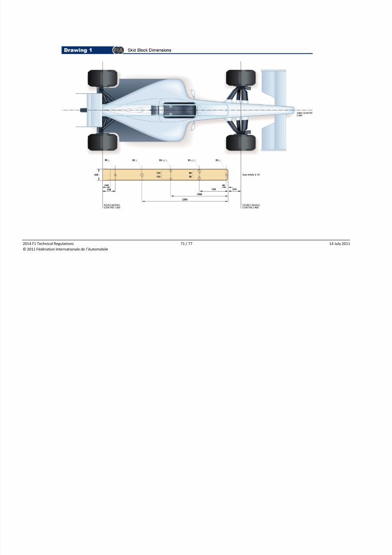
8/6/2019 2014 f1 Technical Regulations - Published on 20.07
http://slidepdf.com/reader/full/2014-f1-technical-regulations-published-on-2007 71/77
2014 F1 Technical Regulations 71 / 77 14 July 2011
© 2011 Fédération Internationale de l’Automobile
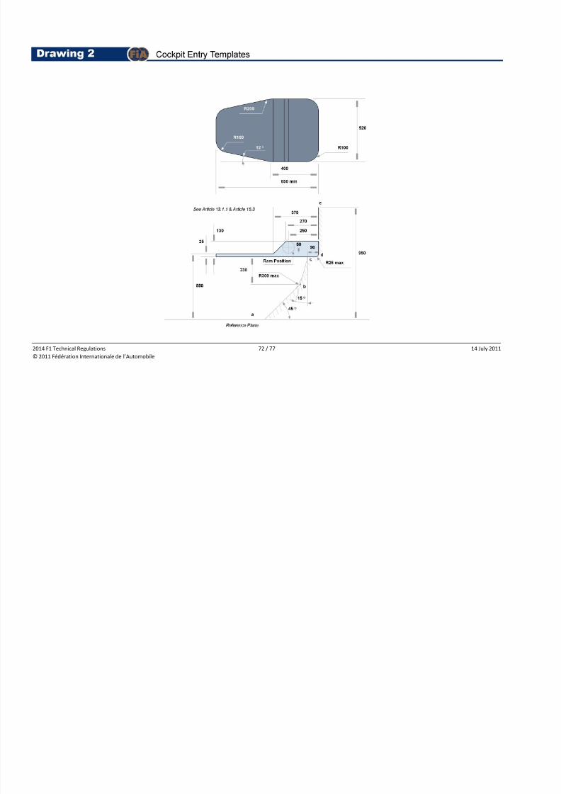
8/6/2019 2014 f1 Technical Regulations - Published on 20.07
http://slidepdf.com/reader/full/2014-f1-technical-regulations-published-on-2007 72/77
2014 F1 Technical Regulations 72 / 77 14 July 2011
© 2011 Fédération Internationale de l’Automobile
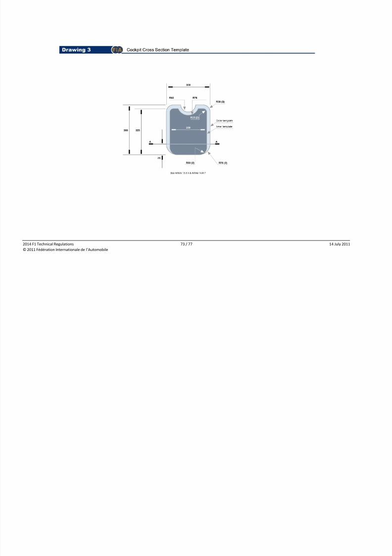
8/6/2019 2014 f1 Technical Regulations - Published on 20.07
http://slidepdf.com/reader/full/2014-f1-technical-regulations-published-on-2007 73/77
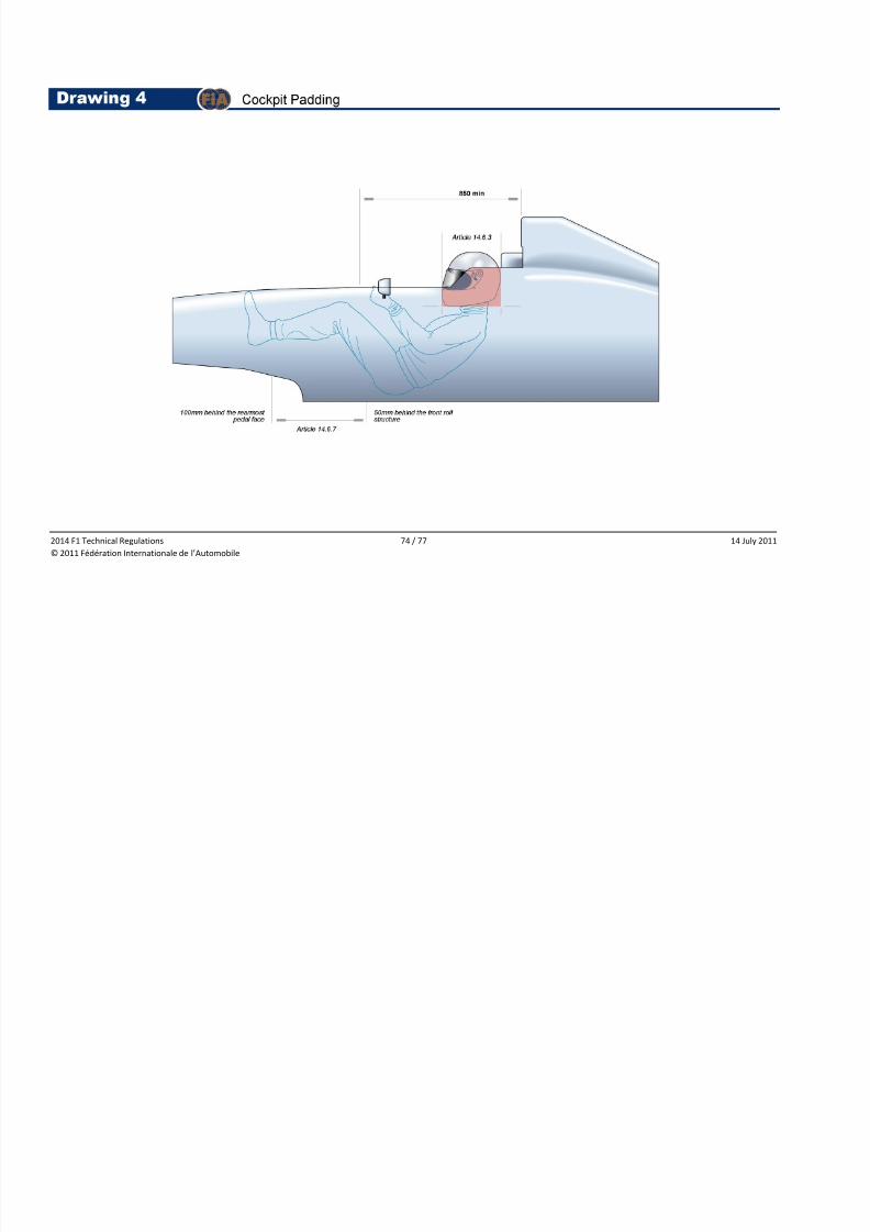
8/6/2019 2014 f1 Technical Regulations - Published on 20.07
http://slidepdf.com/reader/full/2014-f1-technical-regulations-published-on-2007 74/77
2014 F1 Technical Regulations 74 / 77 14 July 2011
© 2011 Fédération Internationale de l’Automobile
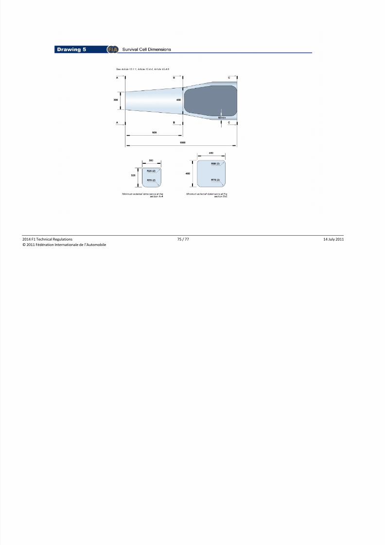
8/6/2019 2014 f1 Technical Regulations - Published on 20.07
http://slidepdf.com/reader/full/2014-f1-technical-regulations-published-on-2007 75/77
2014 F1 Technical Regulations 75 / 77 14 July 2011
© 2011 Fédération Internationale de l’Automobile
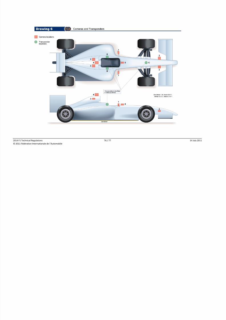
8/6/2019 2014 f1 Technical Regulations - Published on 20.07
http://slidepdf.com/reader/full/2014-f1-technical-regulations-published-on-2007 76/77
2014 F1 Technical Regulations 76 / 77 14 July 2011
© 2011 Fédération Internationale de l’Automobile
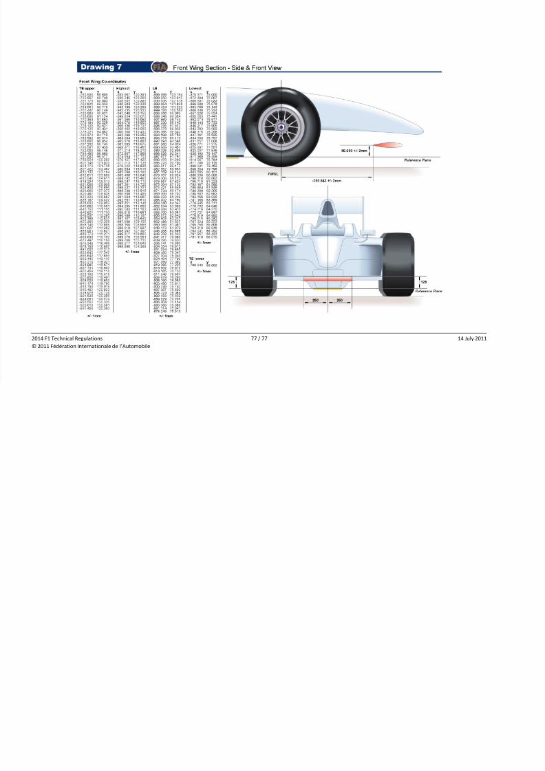
8/6/2019 2014 f1 Technical Regulations - Published on 20.07
http://slidepdf.com/reader/full/2014-f1-technical-regulations-published-on-2007 77/77
2014 F1 Technical Regulations 77 / 77 14 July 2011
© 2011 Fédération Internationale de l’Automobile