Embed Size (px)
Citation preview
2
Copyright
This manual and the programs on theMagellan/SPACE MOUSE/Cyberpuck CD-ROMare protected by copyright of LogiCad3D. Theymust not be copied or distributed without theexpress written permission of LogiCad3D.Violators will be prosecuted to the fullestextent of civil and criminal laws. The right tothese programs and the manual are held by:
LogiCad3D GmbH - A Logitech CompanyAn der Hartmuehle 8D-82229 Seefeld, GermanyTel: + 49 (0) 8152-9919-0Fax: + 49 (0) 8152-9919-50Email: [email protected]: www.logicad3d.com
The information in this manual is subject tochange without notice. LogiCad3D shall not beheld liable for technical or editorial errors oromissions contained herein, nor for incidentalor consequential damages resulting from thefurnishing, performance or use of this material.The information in this manual may not bechanged without special notification. Theinstructions in this manual are checkedregularly and necessary corrections areincluded in all subsequent editions. Morecopies or newer editions of this manual andtechnical information on Cyberpuck can beobtained only from LogiCad3D GmbH.
The citation of names in this manual as a ruledoes not mention existing patents, registereddesigns or trademarks. Missing correspondingremarks do not justify the assumption that thenames may be freely usable. All trademarksare acknowledged where applicable.
NOTICE:The use of the Cyberpuck is primarily intendedfor graphical applications only. The companyLogiCad3D is not liable for any damages(including all kinds of damage from lost profit,operating breakdown, loss of businessinformation, data or other kinds of monetaryloss) that are due to either proper or improperuse of this LogiCad3D product. In any case,LogiCad3D’s liability is restricted to the amountof money paid for the product. This exclusiondoes not hold for damages caused byLogiCad3D intentionally or grossly negligent.In the same way, claims based on generallaws and rules of product liability remainuntouched. For other applications LogiCad3Ddeclines any liability or claims for damages.
Cyberpuck and SPACE MOUSE are registeredEuropean trademarks of LogiCad3D GmbH.
MagellanTM is the US trademark of LogiCad3DInc./GmbH.
This device uses one or more patents held bythe Deutsches Zentrum für Luft- undRaumfahrt e.V. (DLR).
Edited 07/00 by LogiCad3D GmbH - A LogitechCompany, GERMANY.
NOTE: For optimal viewing of this document,it is recommended to use the latest version ofAdobe Acrobat Reader, available on theMagellan/SPACE MOUSE/Cyberpuck driver CD-ROM or at www.adobe.com/acrobat.
3
Contents
Introduction to Cyberpuck ..................... 4
Installation ............................................. 5
Package Contents......................................... 5Hardware Installation ................................... 5Supported Operating Systems ....................... 5Application List & Driver InstallationInstructions.................................................. 6Driver Installation Procedure ......................... 8Startup Tips ................................................. 8Readme Files ............................................... 8
Cyberpuck Features................................ 9
Cyberpuck Virtual Buttons............................. 93D Controller Panel....................................... 9Programming the Virtual Buttons................. 10
Troubleshooting.................................... 11
LogiCad3D Support............................... 12
Appendices ........................................... 13
Connecting to the RS232 Serial Port ............ 13Product Specifications................................. 13
Warranty Information .......................... 14
4
Introduction to Cyberpuck
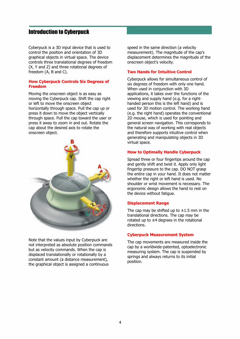
Cyberpuck is a 3D input device that is used tocontrol the position and orientation of 3Dgraphical objects in virtual space. The devicecontrols three translational degrees of freedom(X, Y and Z) and three rotational degrees offreedom (A, B and C).
How Cyberpuck Controls Six Degrees ofFreedom
Moving the onscreen object is as easy asmoving the Cyberpuck cap. Shift the cap rightor left to move the onscreen objecthorizontally through space. Pull the cap up orpress it down to move the object verticallythrough space. Pull the cap toward the user orpress it away to zoom in and out. Rotate thecap about the desired axis to rotate theonscreen object.
Note that the values input by Cyberpuck arenot interpreted as absolute position commandsbut as velocity commands. When the cap isdisplaced translationally or rotationally by aconstant amount (a distance measurement),the graphical object is assigned a continuous
speed in the same direction (a velocitymeasurement). The magnitude of the cap’sdisplacement determines the magnitude of theonscreen object’s velocity.
Two Hands for Intuitive Control
Cyberpuck allows for simultaneous control ofsix degrees of freedom with only one hand.When used in conjunction with 3Dapplications, it takes over the functions of theviewing and supply hand (e.g. for a right-handed person this is the left hand) and isused for 3D motion control. The working hand(e.g. the right hand) operates the conventional2D mouse, which is used for pointing andgeneral screen navigation. This corresponds tothe natural way of working with real objectsand therefore supports intuitive control whengenerating and manipulating objects in 3Dvirtual space.
How to Optimally Handle Cyberpuck
Spread three or four fingertips around the capand gently shift and twist it. Apply only lightfingertip pressure to the cap. DO NOT graspthe entire cap in your hand. It does not matterwhether the right or left hand is used. Noshoulder or wrist movement is necessary. Theergonomic design allows the hand to rest onthe device without fatigue.
Displacement Range
The cap may be shifted up to ±1.5 mm in thetranslational directions. The cap may berotated up to ±4 degrees in the rotationaldirections.
Cyberpuck Measurement System
The cap movements are measured inside thecap by a worldwide-patented, optoelectronicmeasuring system. The cap is suspended bysprings and always returns to its initialposition.
5
Installation
To install the Cyberpuck device and driversoftware on systems running Windows 95, 98,NT (3.51 or higher) or 2000, see theinformation below. For help with installationproblems see Troubleshooting.
Package Contents
The product package contains:
a Cyberpuck 3D input device;
a CD-ROM containing the driver software;and
the product documentation.
Hardware Installation
The Cyberpuck has a serial interface cable witha 9-pin female connector, which must beconnected to the proper serial port (usuallyCOM1 or COM2) of your PC/workstation. Thecable plugs directly into the port at the back ofthe PC/workstation. Be sure to turn off themachine before connecting the Cyberpuck.Once the connections have been made, youcan restore power to the PC/workstation.
Supported Operating Systems
The Cyberpuck driver is supported on thefollowing operating systems:
Win95/98/ PC with Windows 95, 98,NT/2000 NT 3.51 (or higher) or 2000
DECNT Digital EquipmentCorporation with WindowsNT 3.51 or higher
MIPSNT MIPS with Windows NT3.51 or higher
The following pages of this manual list theapplications that support Cyberpuck. Locateyour application in the list and note theimportant installation instructions. Thenproceed to Driver Installation Procedure.
NOTE: If the list indicates that an appropriatedriver is included with your application, youshould consult the application manual for theappropriate Cyberpuck installation procedure.(Note that the information may appear underthe heading Magellan or SPACE MOUSE.) If thelist indicates a file to copy, there is noinstallation tool program for your application.Instead you must manually copy the specifiedfile to your system.
6
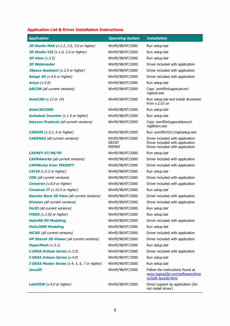
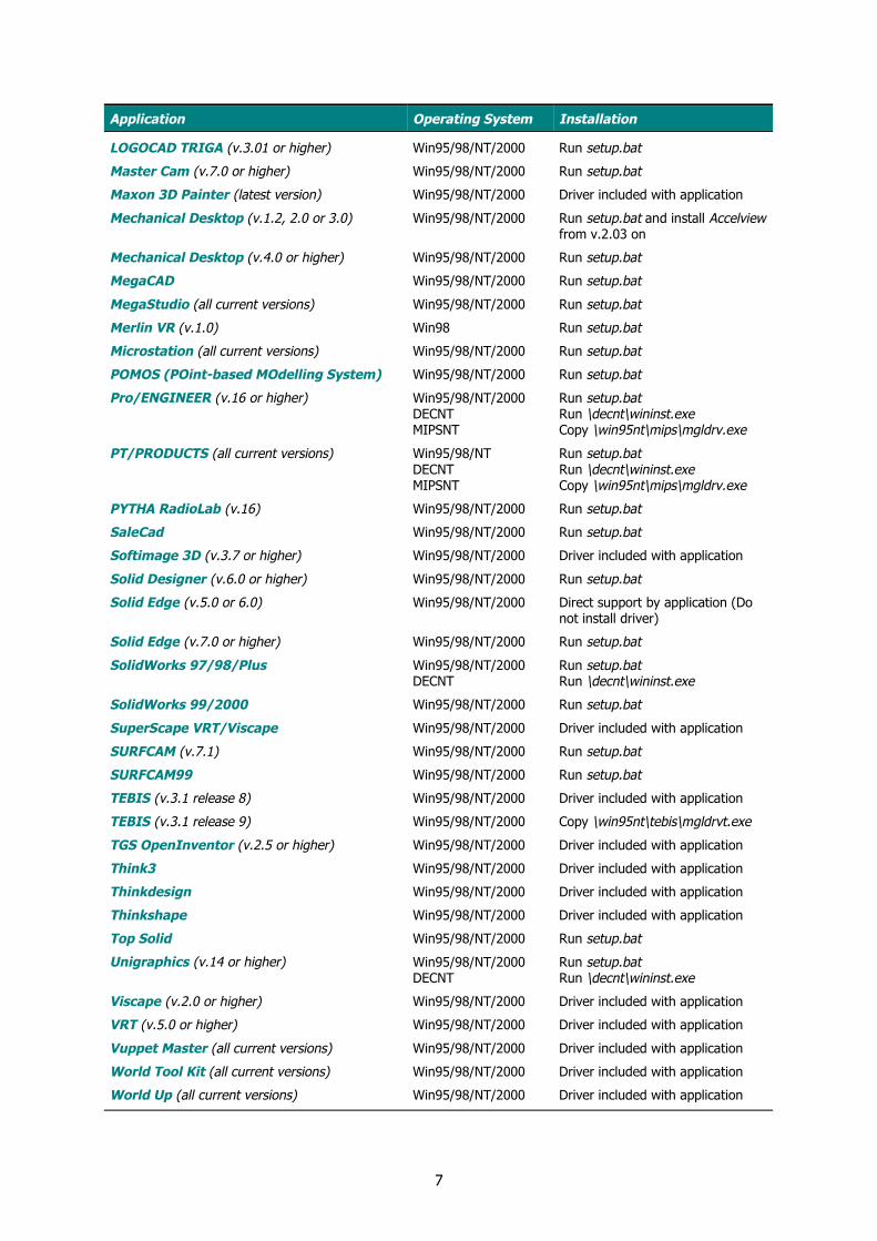
Application List & Driver Installation Instructions
Application Operating System Installation
3D Studio MAX (v.1.2, 2.0, 3.0 or higher) Win95/98/NT/2000 Run setup.bat
3D Studio VIZ (v.1.0, 2.0 or higher) Win95/98/NT/2000 Run setup.bat
3D View (v.3.5) Win95/98/NT/2000 Run setup.bat
3D Webmaster Win95/98/NT/2000 Driver included with application
3Space Assistant (v.2.5 or higher) Win95/98/NT/2000 Driver included with application
Amapi 3D (v.4.0 or higher) Win95/98/NT/2000 Driver included with application
Ansys (v.5.6) Win95/98/NT/2000 Run setup.bat
ARCON (all current versions) Win95/98/NT/2000 Copy \win95nt\apps\arcon\mglxzb.exe
AutoCAD (v.13 or 14) Win95/98/NT/2000 Run setup.bat and install Accelviewfrom v.2.03 on
AutoCAD2000 Win95/98/NT/2000 Run setup.bat
Autodesk Inventor (v.1.0 or higher) Win95/98/NT/2000 Run setup.bat
blaxxun Products (all current versions) Win95/98/NT/2000 Copy \win95nt\apps\blaxxun\mglblxxn.exe
CADDS5 (v.5.2, 6 or higher) Win95/98/NT/2000 Run \win95nt\X11mgl\setup.exe
Win95/98/NT/2000 Driver included with applicationDECNT Driver included with application
CADENAS (all current versions)
MIPSNT Driver included with application
CADKEY 97/98/99 Win95/98/NT/2000 Run setup.bat
CADRAworks (all current versions) Win95/98/NT/2000 Driver included with application
CAMWorks from TEKSOFT Win95/98/NT/2000 Driver included with application
CATIA (v.5.2 or higher) Win95/98/NT/2000 Run setup.bat
CDK (all current versions) Win95/98/NT/2000 Driver included with application
Cimatron (v.8.0 or higher) Win95/98/NT/2000 Driver included with application
Cimatron IT (v.10.5 or higher) Win95/98/NT/2000 Run setup.bat
Daimler Benz 3D View (all current versions) Win95/98/NT/2000 Driver included with application
Division (all current versions) Win95/98/NT/2000 Driver included with application
Do3D (all current versions) Win95/98/NT/2000 Run setup.bat
FIDES (v.3.92 or higher) Win95/98/NT/2000 Run setup.bat
Helix98/99 Modeling Win95/98/NT/2000 Driver included with application
Helix2000 Modeling Win95/98/NT/2000 Run setup.bat
HiCAD (all current versions) Win95/98/NT/2000 Driver included with application
HP Shared 3D Viewer (all current versions) Win95/98/NT/2000 Driver included with application
HyperMesh (v.3.1) Win95/98/NT/2000 Run setup.bat
I-DEAS Artisan Series (v.3.0) Win95/98/NT/2000 Driver included with application
I-DEAS Artisan Series (v.4.0) Win95/98/NT/2000 Run setup.bat
I-DEAS Master Series (v.4, 5, 6, 7 or higher) Win95/98/NT/2000 Run setup.bat
Java3D Win95/98/NT/2000 Follow the instructions found atwww.logicad3d.com/software/drivers/SUN-Java3D.html
LabVIEW (v.4.0 or higher) Win95/98/NT/2000 Direct support by application (Donot install driver)
7
Application Operating System Installation
LOGOCAD TRIGA (v.3.01 or higher) Win95/98/NT/2000 Run setup.bat
Master Cam (v.7.0 or higher) Win95/98/NT/2000 Run setup.bat
Maxon 3D Painter (latest version) Win95/98/NT/2000 Driver included with application
Mechanical Desktop (v.1.2, 2.0 or 3.0) Win95/98/NT/2000 Run setup.bat and install Accelviewfrom v.2.03 on
Mechanical Desktop (v.4.0 or higher) Win95/98/NT/2000 Run setup.bat
MegaCAD Win95/98/NT/2000 Run setup.bat
MegaStudio (all current versions) Win95/98/NT/2000 Run setup.bat
Merlin VR (v.1.0) Win98 Run setup.bat
Microstation (all current versions) Win95/98/NT/2000 Run setup.bat
POMOS (POint-based MOdelling System) Win95/98/NT/2000 Run setup.bat
Win95/98/NT/2000 Run setup.batDECNT Run \decnt\wininst.exe
Pro/ENGINEER (v.16 or higher)
MIPSNT Copy \win95nt\mips\mgldrv.exe
Win95/98/NT Run setup.batDECNT Run \decnt\wininst.exe
PT/PRODUCTS (all current versions)
MIPSNT Copy \win95nt\mips\mgldrv.exe
PYTHA RadioLab (v.16) Win95/98/NT/2000 Run setup.bat
SaleCad Win95/98/NT/2000 Run setup.bat
Softimage 3D (v.3.7 or higher) Win95/98/NT/2000 Driver included with application
Solid Designer (v.6.0 or higher) Win95/98/NT/2000 Run setup.bat
Solid Edge (v.5.0 or 6.0) Win95/98/NT/2000 Direct support by application (Donot install driver)
Solid Edge (v.7.0 or higher) Win95/98/NT/2000 Run setup.bat
Win95/98/NT/2000 Run setup.batSolidWorks 97/98/PlusDECNT Run \decnt\wininst.exe
SolidWorks 99/2000 Win95/98/NT/2000 Run setup.bat
SuperScape VRT/Viscape Win95/98/NT/2000 Driver included with application
SURFCAM (v.7.1) Win95/98/NT/2000 Run setup.bat
SURFCAM99 Win95/98/NT/2000 Run setup.bat
TEBIS (v.3.1 release 8) Win95/98/NT/2000 Driver included with application
TEBIS (v.3.1 release 9) Win95/98/NT/2000 Copy \win95nt\tebis\mgldrvt.exe
TGS OpenInventor (v.2.5 or higher) Win95/98/NT/2000 Driver included with application
Think3 Win95/98/NT/2000 Driver included with application
Thinkdesign Win95/98/NT/2000 Driver included with application
Thinkshape Win95/98/NT/2000 Driver included with application
Top Solid Win95/98/NT/2000 Run setup.bat
Win95/98/NT/2000 Run setup.batUnigraphics (v.14 or higher)DECNT Run \decnt\wininst.exe
Viscape (v.2.0 or higher) Win95/98/NT/2000 Driver included with application
VRT (v.5.0 or higher) Win95/98/NT/2000 Driver included with application
Vuppet Master (all current versions) Win95/98/NT/2000 Driver included with application
World Tool Kit (all current versions) Win95/98/NT/2000 Driver included with application
World Up (all current versions) Win95/98/NT/2000 Driver included with application
8
Driver Installation Procedure
If an appropriate driver has not been includedwith your application, follow the instructionsbelow. For help see Troubleshooting.
1 Insert the CD-ROM into your CD-ROMdrive.
2 The installation program setup.batautomatically begins (if auto-start isactivated on your CD-ROM drive).Continue with this installation programonly if Run setup.bat is listed for yourapplication. (If Run setup.bat is not listedfor your application, you should cancelthe installation and follow the instructionsgiven for your application. SeeApplication List & Driver InstallationInstructions.)
3 Select Cyberpuck installation.
4 Follow the instructions onscreen. Makesure the destination folder is the one towhich you want the driver to be copied.
5 Select the applications with which youwish to use the Cyberpuck.
6 If you select Start the driver now, theCyberpuck should respond with twobeeps indicating that it is receiving powerand working properly. The driver icon willalso appear at the lower-right corner ofthe Windows Taskbar.
7 Select Start the 3D Cube Demo topractice using Cyberpuck.
Startup Tips
In order to use the Cyberpuck, you must startthe driver (BEFORE starting your CADapplication) each time you log on to thesystem. Alternatively, you can put the driver inthe Startup folder, so that it startsautomatically every time you log on. Thedriver icon will appear in the Taskbar if thedriver has been initialized successfully.
Readme Files
To install additional drivers for otherapplications, follow the instructions in theReadme files, which are located on the CD-ROM in subdirectories under the names of theappropriate applications.
9
Cyberpuck Features
Cyberpuck has five fully-programmable “virtualbuttons” and a variety of software featuresthat allow the user to customize the device.
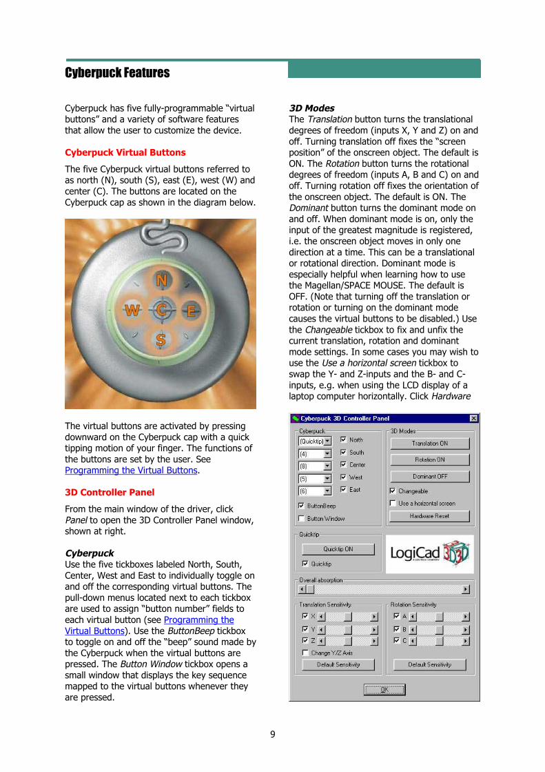
Cyberpuck Virtual Buttons
The five Cyberpuck virtual buttons referred toas north (N), south (S), east (E), west (W) andcenter (C). The buttons are located on theCyberpuck cap as shown in the diagram below.
The virtual buttons are activated by pressingdownward on the Cyberpuck cap with a quicktipping motion of your finger. The functions ofthe buttons are set by the user. SeeProgramming the Virtual Buttons.
3D Controller Panel
From the main window of the driver, clickPanel to open the 3D Controller Panel window,shown at right.
CyberpuckUse the five tickboxes labeled North, South,Center, West and East to individually toggle onand off the corresponding virtual buttons. Thepull-down menus located next to each tickboxare used to assign “button number” fields toeach virtual button (see Programming theVirtual Buttons). Use the ButtonBeep tickboxto toggle on and off the “beep” sound made bythe Cyberpuck when the virtual buttons arepressed. The Button Window tickbox opens asmall window that displays the key sequencemapped to the virtual buttons whenever theyare pressed.
3D ModesThe Translation button turns the translationaldegrees of freedom (inputs X, Y and Z) on andoff. Turning translation off fixes the “screenposition” of the onscreen object. The default isON. The Rotation button turns the rotationaldegrees of freedom (inputs A, B and C) on andoff. Turning rotation off fixes the orientation ofthe onscreen object. The default is ON. TheDominant button turns the dominant mode onand off. When dominant mode is on, only theinput of the greatest magnitude is registered,i.e. the onscreen object moves in only onedirection at a time. This can be a translationalor rotational direction. Dominant mode isespecially helpful when learning how to usethe Magellan/SPACE MOUSE. The default isOFF. (Note that turning off the translation orrotation or turning on the dominant modecauses the virtual buttons to be disabled.) Usethe Changeable tickbox to fix and unfix thecurrent translation, rotation and dominantmode settings. In some cases you may wish touse the Use a horizontal screen tickbox toswap the Y- and Z-inputs and the B- and C-inputs, e.g. when using the LCD display of alaptop computer horizontally. Click Hardware
10
Reset to redefine the zero position of the cap,e.g. if the onscreen object begins to drift.
QuicktipUse the Quicktip button to collectively toggleon and off the virtual buttons. Untick theQuicktip tickbox to completely disable thevirtual buttons.
Overall AbsorptionUse this slider bar to adjust the minimumdisplacement of the cap necessary to causemovement of the onscreen object. Increasingthe overall absorption may be helpful in workenvironments with vibrations (e.g. industrialenvironments), which may cause theCyberpuck to register unintentionalmovements.
Translation SensitivityUse the slider bars to individually adjust thesensitivities of each translational degree offreedom. As an example, it may be useful tohave faster zoom response (Z-sensitivity) thanpan response (X- and Y-sensitivity). As thesensitivity is increased, the same movementsof the Cyberpuck cap will generate quickertranslations of the onscreen object. Use thetickboxes next to the adjustment bars totoggle on and off the individual degrees offreedom. Click Default Sensitivity to reset allthree slider bars to their default settings. Notethat for some CAD applications it may benecessary to tick the Change Y/Z Axis box,which swaps the Y- and Z-inputs.
Rotation SensitivityUse the slider bars to individually adjust thesensitivities of each rotational degree offreedom. As the sensitivity is increased, thesame movements of the Cyberpuck cap willgenerate quicker rotations of the onscreenobject. Use the tickboxes next to theadjustment bars to toggle on and off theindividual degrees of freedom. Click DefaultSensitivity to reset all three slider bars to theirdefault settings.
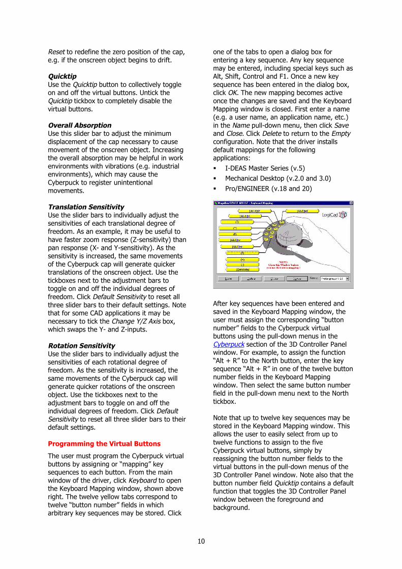
Programming the Virtual Buttons
The user must program the Cyberpuck virtualbuttons by assigning or “mapping” keysequences to each button. From the mainwindow of the driver, click Keyboard to openthe Keyboard Mapping window, shown aboveright. The twelve yellow tabs correspond totwelve “button number” fields in whicharbitrary key sequences may be stored. Click
one of the tabs to open a dialog box forentering a key sequence. Any key sequencemay be entered, including special keys such asAlt, Shift, Control and F1. Once a new keysequence has been entered in the dialog box,click OK. The new mapping becomes activeonce the changes are saved and the KeyboardMapping window is closed. First enter a name(e.g. a user name, an application name, etc.)in the Name pull-down menu, then click Saveand Close. Click Delete to return to the Emptyconfiguration. Note that the driver installsdefault mappings for the followingapplications: I-DEAS Master Series (v.5) Mechanical Desktop (v.2.0 and 3.0) Pro/ENGINEER (v.18 and 20)
After key sequences have been entered andsaved in the Keyboard Mapping window, theuser must assign the corresponding “buttonnumber” fields to the Cyberpuck virtualbuttons using the pull-down menus in theCyberpuck section of the 3D Controller Panelwindow. For example, to assign the function“Alt + R” to the North button, enter the keysequence “Alt + R” in one of the twelve buttonnumber fields in the Keyboard Mappingwindow. Then select the same button numberfield in the pull-down menu next to the Northtickbox.
Note that up to twelve key sequences may bestored in the Keyboard Mapping window. Thisallows the user to easily select from up totwelve functions to assign to the fiveCyberpuck virtual buttons, simply byreassigning the button number fields to thevirtual buttons in the pull-down menus of the3D Controller Panel window. Note also that thebutton number field Quicktip contains a defaultfunction that toggles the 3D Controller Panelwindow between the foreground andbackground.
11
Troubleshooting
Problem/Error Possible Explanations Recommended Actions
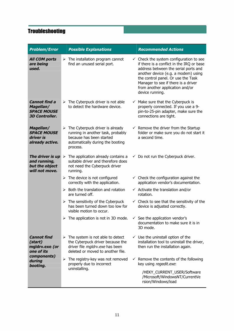
All COM portsare beingused.
The installation program cannotfind an unused serial port.
Check the system configuration to seeif there is a conflict in the IRQ or baseaddress between the serial ports andanother device (e.g. a modem) usingthe control panel. Or use the TaskManager to see if there is a driverfrom another application and/ordevice running.
Cannot find aMagellan/SPACE MOUSE3D Controller.
The Cyberpuck driver is not ableto detect the hardware device.
Make sure that the Cyberpuck isproperly connected. If you use a 9-pin-to-25-pin adapter, make sure theconnections are tight.
Magellan/SPACE MOUSEdriver isalready active.
The Cyberpuck driver is alreadyrunning in another task, probablybecause has been startedautomatically during the bootingprocess.
Remove the driver from the Startupfolder or make sure you do not start ita second time.
The application already contains asuitable driver and therefore doesnot need the Cyberpuck driverrunning.
Do not run the Cyberpuck driver.
The device is not configuredcorrectly with the application.
Check the configuration against theapplication vendor’s documentation.
Both the translation and rotationare turned off.
Activate the translation and/orrotation.
The sensitivity of the Cyberpuckhas been turned down too low forvisible motion to occur.
Check to see that the sensitivity of thedevice is adjusted correctly.
The driver is upand running,but the objectwill not move.
The application is not in 3D mode. See the application vendor’sdocumentation to make sure it is in3D mode.
The system is not able to detectthe Cyberpuck driver because thedriver file mgldrv.exe has beendeleted or moved to another file.
Use the uninstall option of theinstallation tool to uninstall the driver,then run the installation again.
Cannot find(start)mgldrv.exe (orone of itscomponents)duringbooting.
The registry-key was not removedproperly due to incorrectuninstalling.
Remove the contents of the followingkey using regedit.exe:
/HEKY_CURRENT_USER/Software/Microsoft/WindowsNT/CurrentVersion/Windows/load

12
LogiCad3D Support
If you have any questions or comments aboutthe Cyberpuck product, please contact thepersons or organizations listed for your area.Various information about the Cyberpuck,including the latest driver versions, can befound at the web sites.
America & Asia
LogiCad3D, Inc.17672 Laurel Park Drive North, Suite 400Livonia, MI 48152U.S.A.Tel: + 1-734-591-4047Fax: + 1-734-591-4064Email: [email protected]: www.logicad3d.com
Marketing & SalesMiguel LeitmannTel: + 1-734-591-4047Email: [email protected]
SupportTel: + 1-800-540-4758Email: [email protected]
HelpEmail: [email protected]
EMEA (Europe, Middle East & Africa)
LogiCad3D GmbHAn der Hartmuehle 8D-82229 SeefeldGermanyTel: + 49 (0) 8152-9919-0Fax: + 49 (0) 8152-9919-50Email: [email protected]: www.spacemouse.com
Marketing & SalesRalf StetterTel: + 49 (0) 8152-9919-0Email: [email protected]
SupportTel: + 49 (0) 8152-9919-44Email: [email protected]
HelpEmail: [email protected]
13
Appendices
Connecting to the RS232 Serial Port
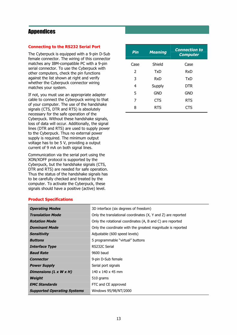
The Cyberpuck is equipped with a 9-pin D-Subfemale connector. The wiring of this connectormatches any IBM-compatible PC with a 9-pinserial connector. To use the Cyberpuck withother computers, check the pin functionsagainst the list shown at right and verifywhether the Cyberpuck connector wiringmatches your system.
If not, you must use an appropriate adaptercable to connect the Cyberpuck wiring to thatof your computer. The use of the handshakesignals (CTS, DTR and RTS) is absolutelynecessary for the safe operation of theCyberpuck. Without these handshake signals,loss of data will occur. Additionally, the signallines (DTR and RTS) are used to supply powerto the Cyberpuck. Thus no external powersupply is required. The minimum outputvoltage has to be 5 V, providing a outputcurrent of 9 mA on both signal lines.
Communication via the serial port using theXON/XOFF protocol is supported by theCyberpuck, but the handshake signals (CTS,DTR and RTS) are needed for safe operation.Thus the status of the handshake signals hasto be carefully checked and treated by thecomputer. To activate the Cyberpuck, thesesignals should have a positive (active) level.
Pin Meaning Connection toComputer
Case Shield Case
2 TxD RxD
3 RxD TxD
4 Supply DTR
5 GND GND
7 CTS RTS
8 RTS CTS
Product Specifications
Operating Modes 3D interface (six degrees of freedom)
Translation Mode Only the translational coordinates (X, Y and Z) are reported
Rotation Mode Only the rotational coordinates (A, B and C) are reported
Dominant Mode Only the coordinate with the greatest magnitude is reported
Sensitivity Adjustable (600 speed levels)
Buttons 5 programmable “virtual” buttons
Interface Type RS232C Serial
Baud Rate 9600 baud
Connector 9-pin D-Sub female
Power Supply Serial port signals
Dimensions (L x W x H) 140 x 140 x 45 mm
Weight 510 grams
EMC Standards FTC and CE approved
Supported Operating Systems Windows 95/98/NT/2000
14
Warranty Information
LogiCad3D’s Limited Lifetime HardwareWarranty
LogiCad3D warrants that Cyberpuck is freefrom significant defects in materials andworkmanship under normal use for as long asthe device is owned. During the first threeyears of ownership, LogiCad3D will at its soleoption, replace or repair at no charge theproduct, which in its opinion is defective.
During the remaining years of the warranty,LogiCad3D will, at its sole option, replace orrepair the defective product. LogiCad3D willcharge a fixed fee to cover handling andservice costs based on LogiCad3D's thencurrent price schedules. LogiCad3D at its soleoption, may replace or repair the defectiveproduct with a then current product havingsimilar features and functionality asdetermined by LogiCad3D.
Damages or defects to the product caused byimproper installation, modification, misuse orabuse are not, of course, covered by thiswarranty. Additionally, the warranty serviceoffered above is nontransferable, which meansthat the particular warranty service describedabove is available only to the originalpurchaser of the product(s). If LogiCad3Ddetermines that the product is not defective orwas not under warranty, it will return theproduct(s) to you, freight collect.
To obtain warranty service, you must either(a) have a completed warranty registrationcard on file at LogiCad3D, or (b) submitacceptable proof of purchase (for instance, acopy of your sales receipt indicating date andplace of purchase) to LogiCad3D’s CustomerService Department. You will need to pack theproduct to be returned properly for shipmentand pay any applicable shipping charges.LogiCad3D will send you the repaired orreplaced product at its own expense.
LOGICAD3D DISCLAIMS ALL OTHERWARRANTIES, EITHER EXPRESS OR IMPLIED,INCLUDING BUT NOT LIMITED TO IMPLIEDWARRANTIES OF MERCHANTABILITY ANDFITNESS FOR A PARTICULAR PURPOSE WITHREGARD TO THE PRODUCT. IN NO EVENTSHALL LOGICAD3D OR ITS SUPPLIERS BEHELD LIABLE FOR ANY DIRECT, INDIRECT,CONSEQUENTIAL OR INCIDENTAL DAMAGES
ARISING OUT OF THE USE OF OR INABILITYTO USE THE PRODUCT, EVEN IF LOGICAD3DHAS BEEN ADVISED OF THE POSSIBILITY OFSUCH DAMAGES. SOME STATES DO NOTALLOW THE EXCLUSION OR LIMITATION OFLIABILITY FOR CONSEQUENTIAL ORINCIDENTAL DAMAGES, SO THE ABOVELIMITATION MAY NOT APPLY TO YOU.
FCC Compliance Statement
This device complies with Part 15 of the FCCRules. Operation is subject to the followingtwo conditions:1) This device may not cause harmful
interference.2) This device must accept any interference
received, including interference that maycause undesired operation.
FCC Declaration of Conformance
Trade Name: Silicon Graphics, Inc.Product: Computer Graphics WorkstationModel Number: CMNBO15BDate of Conformance: 1/97Responsible Party: Silicon Graphics, Inc.Address: 2011 North Shoreline Boulevard
Mountain View, CA 94043-1389U.S.A.
Tel: 650 933-1071
This equipment complies with Part 15 of theFCC Rules. Operation is subject to thefollowing two conditions:1) This device may not cause harmful
interference.2) This device must accept any interference
received, including interference that maycause undesired operation.
NOTE: This equipment has been tested andfound to comply with the limits for a Class Bdigital device, pursuant to Part 15 of the FCCRules. These limits are designed to providereasonable protection against harmfulinterference in a residential installation. Thisequipment generates, uses and can radiateradio frequency energy and, if not installedand used in accordance with the instructions,may cause harmful interference to radiocommunications. However, there is noguarantee that interference will not occur in aparticular installation. If this equipment doescause harmful interference to radio or
15
television reception, which can be determinedby turning the equipment off and on, the useris encouraged to try to correct the interferenceby one or more of the following measures:
Reorient or relocate the receiving antenna.
Increase the separation between theequipment and receiver.
Connect the equipment into an outlet on acircuit different from that to which thereceiver is connected.
Consult the dealer or an experiencedradio/TV technician for help.
CAUTION: The user is cautioned that changesor modifications to the equipment notexpressly approved by the party responsiblefor compliance could void the user’s authorityto operate the equipment.
European Economic CommunityDeclaration of Conformance (CE)
The Cyberpuck is attested to meet theessential protection requirements againstelectromagnetic emission, which areestablished in the regulations of the council forassimilating the rules and regulations of themember states about electromagneticcompatibility 89/336/EEC and changed byregulation 92/31 EEC. This declaration is validfor all samples produced according to theenclosed production drawings, which are partof this declaration. The following standardswere used for judging the product concerningelectromagnetic capability: For trouble emission: EN55022
edition: 05/95 For trouble security: EN50082-1
edition: 03/93
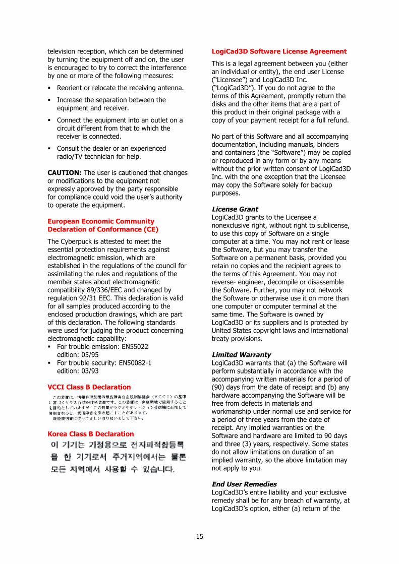
VCCI Class B Declaration
Korea Class B Declaration
LogiCad3D Software License Agreement
This is a legal agreement between you (eitheran individual or entity), the end user License(“Licensee”) and LogiCad3D Inc.(“LogiCad3D”). If you do not agree to theterms of this Agreement, promptly return thedisks and the other items that are a part ofthis product in their original package with acopy of your payment receipt for a full refund.
No part of this Software and all accompanyingdocumentation, including manuals, bindersand containers (the “Software”) may be copiedor reproduced in any form or by any meanswithout the prior written consent of LogiCad3DInc. with the one exception that the Licenseemay copy the Software solely for backuppurposes.
License GrantLogiCad3D grants to the Licensee anonexclusive right, without right to sublicense,to use this copy of Software on a singlecomputer at a time. You may not rent or leasethe Software, but you may transfer theSoftware on a permanent basis, provided youretain no copies and the recipient agrees tothe terms of this Agreement. You may notreverse- engineer, decompile or disassemblethe Software. Further, you may not networkthe Software or otherwise use it on more thanone computer or computer terminal at thesame time. The Software is owned byLogiCad3D or its suppliers and is protected byUnited States copyright laws and internationaltreaty provisions.
Limited WarrantyLogiCad3D warrants that (a) the Software willperform substantially in accordance with theaccompanying written materials for a period of(90) days from the date of receipt and (b) anyhardware accompanying the Software will befree from defects in materials andworkmanship under normal use and service fora period of three years from the date ofreceipt. Any implied warranties on theSoftware and hardware are limited to 90 daysand three (3) years, respectively. Some statesdo not allow limitations on duration of animplied warranty, so the above limitation maynot apply to you.
End User RemediesLogiCad3D’s entire liability and your exclusiveremedy shall be for any breach of warranty, atLogiCad3D’s option, either (a) return of the
16
price paid or (b) repair or replacement of theSoftware or hardware that does not meetLogiCad3D's Limited Warranty; provided thatthe Software and hardware must be returnedeither to LogiCad3D or to the point ofpurchase with a copy of your receipt. ThisLimited Warranty is void if failure of theSoftware and or hardware has resulted fromaccident, abuse or misapplication. Anyreplacement Software or hardware will bewarranted for the remainder of the originalwarranty period or 30 days, whichever islonger.
No Other WarrantiesLOGICAD3D DOES NOT WARRANT THESOFTWARE IS ERROR-FREE. LOGICAD3DDISCLAIMS ALL OTHER WARRANTIES, EITHEREXPRESS OR IMPLIED, INCLUDING BUT NOTLIMITED TO IMPLIED WARRANTIES OFMERCHANTABILITY, FITNESS FOR APARTICULAR PURPOSE ANDNONINFRINGEMENT OF THIRD-PARTYRIGHTS WITH RESPECT TO THE SOFTWAREOR HARDWARE. LOGICAD3D’S LIMITEDWARRANTY GIVES YOU SPECIFIC LEGALRIGHTS. YOU MAY HAVE OTHERS, WHICHVARY FROM STATE TO STATE.
Limitation of LiabilitiesIN NO EVENT SHALL LOGICAD3D OR ITSSUPPLIERS BE LIABLE FOR ANYCONSEQUENTIAL, INCIDENTAL OR INDIRECTDAMAGES OF ANY KIND WHATSOEVER(INCLUDING, WITHOUT LIMITATION,DAMAGES FOR LOSS OF BUSINESS PROFITS,BUSINESS INTERRUPTION, LOSS OF
BUSINESS INFORMATION OR OTHERPECUNIARY LOSS) ARISING OUT OF THE USEOF OR INABILITY TO USE THIS LOGICAD3DPRODUCT, EVEN IF LOGICAD3D HAS BEENADVISED OF THE POSSIBILITY OF SUCHDAMAGES. IN NO EVENT SHALL LOGICAD3D’SLIABILITY EXCEED THE LICENSE FEE PAID.BECAUSE SOME STATES DO NOT ALLOW THEEXCLUSION OR LIMITATION OF LIABILITYFOR CONSEQUENTIAL OR INCIDENTALDAMAGES, THE ABOVE LIMITATIONS MAYNOT APPLY TO YOU.
TermsThis license is effective until terminated. Youmay terminate it at any time by destroying theSoftware. It will also terminate upon conditionsset forth elsewhere in this Agreement or if youfail to comply with any terms or conditions ofthis Agreement. You agree upon suchtermination to destroy the Software togetherwith all copies, modifications and mergedportions in any form.
GeneralThis is the entire agreement between you andLogiCad3D, superseding any prior agreementwhether written or oral relating to the subjectmatter of this Agreement. In the event ofinvalidity of any provision of this Agreement,the parties agree that such invalidity shall notaffect the validity of the remaining potions ofthe Agreement. This Agreement will begoverned by the laws of the state of California.The United Nations Convention on Contractsfor the International Sale of Goods isspecifically disclaimed.