Embed Size (px)
Citation preview

C A L I F O R N I A E N E R G Y C O M M I S S I O N1
2013 N id ti l E2013 Nonresidential Energy Standards OverviewStandards Overview
Christopher OlveraCalifornia Energy CommissionOutreach and Education UnitO U

C A L I F O R N I A E N E R G Y C O M M I S S I O N2
Goals of this Course• Identify/clarify the major changes in the 2013 Energy
Standards for nonresidential newly constructed b ildi dditi d lt tibuildings, additions, and alterations (in sequential order of §)
• Simplify compliance and enforcement for the 2013 p y pchanges during:
The plan review process (Plans Examiners)The plan review process (Plans Examiners)Identify what to look for on the compliance forms and building plans
The field inspection process (Field Inspectors)The field inspection process (Field Inspectors)Identify which building components and forms to verify

C A L I F O R N I A E N E R G Y C O M M I S S I O N3
QUESTIONS…• Question sessions
30 minutes before lunch
30 minutes before endRaise hand to ask questionRaise hand to ask question
• All other questionsType into Q and A box at anytime
List of Q and A from webinar will be posted online

C A L I F O R N I A E N E R G Y C O M M I S S I O N4
Let’s discuss the 2013 Building Energy Efficiency
Standards

C A L I F O R N I A E N E R G Y C O M M I S S I O N5
2013 Nonresidential Energy S iSavings
• Overall, 30% “better” th 2008 St d dthan 2008 Standards
• 2013 Nonres. S d d ill
53%
15%
32%
Newly Constructed
Process Energy
Alterations
Standards will save:
372 GWH/yr
6.7 Mtherms/yr
84 MW (first year)84 MW (first year)

C A L I F O R N I A E N E R G Y C O M M I S S I O N6
2013 Building Energy Efficiency StandardsEfficiency Standards
• Effective on July 1, 2014Building permit applications submitted on or after this ddate
• Larger projects in plan review may be affected:
Need to resubmit if permits ll d / f ff i dpulled on/after effective date

C A L I F O R N I A E N E R G Y C O M M I S S I O N7
2013 Documents• Building Energy
Efficiency Standards
• Nonresidential Compliance ManualCompliance Manual
• Reference Appendices
• All docs. available online at:online at:www.energy.ca.gov/title24

C A L I F O R N I A E N E R G Y C O M M I S S I O N8
Summary of Major Changes• Section #s (see cheat sheet
handout)• Covered Processes
Fi ld T h i i• Forms nomenclature
MECH 1C → NRCC MCH 01
• Field Technician Certification
A t T tiMECH-1C → NRCC-MCH-01
LTG-2A → NRCA-LTI-02-A
i i C i i i
Acceptance Testing
• Compliance Form • Building Commissioning
• Solar Zone ready reqs.
RegistrationEffective 1/1/2015
* See summary of changes handout

2013 Energy Standards Section # Cheat Sheet
2008 Section # 2013 Section #
100 100.0 101 100.1 102 100.2 110 110.0 111 110.1 112 110.2 113 110.3 114 110.4 115 110.5 116 110.6 117 110.7 118 110.8 119 110.9
- 110.10 120 120.0 121 120.1 122 120.2 123 120.3 124 120.4 125 120.5 126 120.6
- 120.7 - 120.8 - 120.9
130 130.0 131 130.1 132 130.2 133 130.3 134 130.4
- 130.5 140 140.0 141 140.1 142 140.2 143 140.3 144 140.4 145 140.5 146 140.6 147 140.7 148 140.8
- 140.9 149 141.0
- 141.1 150 150.0 151 150.1 152 150.2

1.5 What’s New for 2013
The process to develop the 2013 Standards began with a call for ideas in winter of 2010, moved through a series of IOU Sponsored stakeholder meetings throughout the state, Energy Commission staff workshops and Energy Commission hearings in 2011 through 2012 and concluded at the adoption hearing on May 23, 2012. Energy Commission staff, contractors, utilities and many others participated in the process. The following paragraphs summarize the principle changes that resulted.
1.5.1 All Buildings Revisions to the administrative §10-103 sets the format and informational order for electronic compliance document registration and submittal and for electronic retention of compliance documentation, including the nonresidential forms, for future use and clarifies the roles and responsibilities of the documentation author and the responsible person;
1. §10-109 describes the rules for approving compliance software, alternative
component packages, exceptional methods, data registries and related data input software, or electronic document repositories.
2. §10-111 describes the rules for reporting fenestration U-factor, SHGC, and VT.
3. §110.3(c)5 explains the requirements for the water heating recirculation loops serving multiple dwelling units, high-rise residential, hotel/motel, and nonresidential occupancies..
4. Revisions to §110.9 now covers ballasts and luminaires and residential vacancy sensors.
1.5.2 Nonresidential Buildings
Envelope 1. Increased low-slope cool roof requirements (increase reflectance from 0.55 to
0.63 for new construction and alterations). (§140.3(a)1Aia1). 2. Established a maximum air leakage rate (0.04 cfm/sf) except in mild climate
zones. (§140.3(a)9B). 3. Increased fenestration requirements to reduce solar gains and increase
visual transmittance for daylighting; 0.36 U-factor, 0.25 SHGC, VT 0.42 for fixed windows; the numbers are different for operable windows and skylights. (§140.3(a)5B,C & D).
4. Fenestration. The Standards now include Dynamic Glazing, Window Films and new maximum values for Visible Transmittance (VT). New Dynamic Glazing, Window Films requirements and changes are in the Reference Nonresidential Appendix NA6 and NA7.4.
5. Added mandatory Roof insulation requirements and minimum insulation for demising walls. (§110.8(e) & (f)).

Lighting 1. Clarification and simplification of existing language; removing exceptions no
longer relevant. (§130.0-130.5, 140.6-140.8). 2. Lighting control devices moving from Title 24 Part 6 to Title 20; Lighting
control systems shall now be acceptance tested for Title 24. (§110.9(b) & §130.4(a)).
3. Nonresidential indoor lighting, advanced multi-level lighting controls (controllable ballasts) increased in granularity (in addition to ON/OFF, increasing from one intermediate level to three intermediate levels for or continuous dimming), favoring dimmable ballasts for linear fluorescent lighting systems. These controls will allow precise and non-interruptive adjustment of lighting to match the available daylighting, and provide dimming and demand response function throughout the building. (§130.1(a) 2C) & §130.1(b).
4. Enhancing, modifying, and adding to the prescriptive and mandatory daylighting control requirements; daylighting language significantly simplified. (§130.1(d) & (§140.6(d)).
5. Requirements for demand responsive reduction of lighting power being applied to smaller spaces. (§130.1(e)).
6. Mandatory Automated Lighting Controls and Switching Requirements in Warehouses and Libraries - Require the installation of occupancy sensors in warehouse aisle ways and open spaces, and library stack aisles. (§130.1(c)6A & B).
7. Mandatory automated lighting controls and switching requirements for hotels and multifamily building corridors - Require the installation of occupancy sensors in corridors and stairwells in lodging and multifamily buildings. (§130.1(c)6C).
8. New mandatory occupancy sensor and daylighting controls in parking garage spaces. (§130.1(d)3).
9. Increased requirements for multi-level lighting controls for nonresidential outdoor lighting. (§130.2(c)3B).
10. Alternate path to comply with existing outdoor lighting cutoff (shielding) requirements, phasing in the new Backlight, Uplight, Glare (BUG) requirements. (§130.2(b)).
11. Reduction of allowed lighting power density for some nonresidential indoor and outdoor lighting applications. (§140.6(c) and §140.7(d))
12. Tailored lighting revisions - Reduce the allowed LPD for Floor Display, Wall Display, and Ornamental Lighting under the Tailored Compliance. §140.6(c)3I, J & K).
13. Plug Load Circuit Controls - requiring automatic shut-off controls of electric circuits that serve plug loads, including task lightings, in office buildings. (§130.5(d)1).
14. Hotel/Motel Guest Room Occupancy Controls for HVAC and lighting systems - would require installation of occupancy controls for HVAC equipment, and

all lighting fixtures in hotel/motel guest rooms, including plug-in lighting. (§120.2(e)4 & §130.1(c)8).
15. Reduction of threshold when lighting alterations must comply with the Standards, from when 50% of the luminaires are replaced, to when 10% of the luminaires are replaced. Consistent with proposed changes to ASHRAE 90.1-2010. (§141.0(b)2I & J).
Mechanical 1. Added requirements for Fan Control and Integrated Economizers. Packaged
units down to 6 tons must be VAV with the ability to modulate cooling capacity to 20% of maximum. Economizers must also be able to modulate cooling capacity to match VAV units. (§140.4(c) & (e))
2. Reduced ability for HVAC systems to reheat conditioned air. (§140.4(d)) 3. Increased chiller efficiency requirements, consistent with ASHRAE 90.1-
2010. (§140.4(i)) 4. Increased cooling tower energy efficiency and WATER Savings. (§140.4(k)2) 5. Added requirements for commercial boiler combustion controls. (§140.4(k)3) 6. Added acceptance tests for HVAC sensors and controls, including those for
demand controlled ventilation. (§120.5(a)) 7. Added efficiency requirements for small motors. (§140.4(c)4) 8. Added credit for evaporative systems that meet the Western Cooling
Efficiency Challenge (WCEC program to acknowledge high energy and water efficiency in evaporative systems).
9. Moving Fault Detection and Diagnostics (FDD) protocols for air temperature, economizers, damper modulation, and excess outdoor air to mandatory measures from the current compliance option. (§120.2(i))
Electrical 1. Added mandatory requirement for receptacle controls in private offices, open
office areas, reception lobbies, conference rooms, kitchens, and copy rooms to automatically shut off task lighting and other plug loads when the area is not occupied. (§130.5(d)).
2. Added mandatory requirement for electrical panels to be isolated by energy end use (e.g. lighting, HVAC, plug loads). (§130.5(b)2).
Covered Processes The 2013 Standards now cover some specific process energy applications, such as supermarket refrigeration, refrigerated warehouses, commercial kitchen ventilation requirements, laboratory exhaust, parking garage ventilation, compressed air, and computer rooms. Definitions for Covered Processes and Exempt Processes were added. Covered Processes are defined as processes for which there are listed requirements. All other processes are Exempt Processes. Specific requirements for Covered Processes are in separate sections (§120.6 Mandatory and §140.9 Prescriptive). It should be noted that the HVAC equipment efficiencies in §110.1 and §110.2 also apply to Covered Processes. In the 2013 Standards, the Covered Processes include:

1. Increased mandatory requirements for refrigerated warehouses (§120.6(a)) 2. Added mandatory requirements for commercial supermarket refrigeration
(§120.6(b)). 3. Added mandatory ventilation control requirements for parking garages
(§120.6(c)). 4. Added mandatory requirements for process boilers (§120.6(d)) 5. Added mandatory requirements for storage and unloading for compressed air
systems (§120.6(e)).Added prescriptive requirements for HVAC systems serving computer rooms (§140.9(a)).
6. Added prescriptive ventilation control requirements for commercial kitchens (§140.9(b)).
7. Added prescriptive requirements for variable air volume for laboratory exhaust systems. (§140.9(c)).
Solar Ready 1. Added mandatory requirements for nonresidential buildings (3 stories or less)
to make provisions to more easily enable the future addition of solar electric or solar water heating systems. (§110.10(a)4).
Commissioning 1. Moved Part 11 commissioning requirements to Part 6 for energy-related
building components. (§120.8). 2. Added mandatory requirements for design-phase commissioning, which
includes an early review of design intent documents and highlighting efficiency specifications in both construction documents and Standards compliance forms. (§120.8(d)).
Compliance Option
Hybrid Evaporative Cooling Systems in Nonresidential Buildings

C A L I F O R N I A E N E R G Y C O M M I S S I O N9
Let’s talk about the changes to the Administrative
Regulations§10 103§10-103

C A L I F O R N I A E N E R G Y C O M M I S S I O N10
Signatures, Registration, Technician CertificationTechnician Certification
2008 – §10-103(a)1, 3, 4, 5 2013 – §10-103(a)1, 3, 4, 5• Designer/Builder and Doc. Author
signatures req. on Certificate of Compliance (-1C forms)
• Doc. Author signature on Certificate of:
Installation (NRCI)• Contractor/Installer signature req. of
Certificate of Installation (-INST)
Installation (NRCI)
Acceptance (NRCA)
Field verification and diagnostic • Field Technician and Contractor
signatures req. on Certificate of Acceptance (-A forms)
testing (NRCV)
• Registration req. for ALL forms effective 1/1/15
• HERS Rater signature req. on Certificate of Field verification and diagnostic testing (HERS)
Contingent upon approval of nonres. data registry

C A L I F O R N I A E N E R G Y C O M M I S S I O N11
Signatures, Registration, Technician Certification contTechnician Certification cont.
• New Acceptance Test Technician Certification Provider (ATTCP) i §10 103 A d §10 103 B(ATTCP) reqs. in §10-103-A and §10-103-B
• Field Technician must be trained and certified by ATTCP d iATTCP to conduct acceptance testing
Employer (contractor) training also req.A li bl t M h i l A t T tiApplicable to Mechanical Acceptance Testing Applicable to Lighting Acceptance Testing
• Effective when thresholds in Standards are met• Effective when thresholds in Standards are met
• Info. available at: http://www.energy.ca.gov/title24/2013standards/provider_cert/

2013 Building Energy Efficiency Standards Page 15
SECTION 10-103-A – NONRESIDENTIAL LIGHTING CONTROLS ACCEPTANCE TEST TRAINING AND CERTIFICATION
Such verification shall include determination that:
A. All installed features, materials, components or manufactured devices, regulated by the Appliance Efficiency Regulations or Part 6 are indicated, when applicable, on the Certificate(s) of Installation, Certificate(s) of Acceptance and Certificate(s) of Verification , and are consistent with such features, materials, components or manufactured devices given in the plans and specifications and the Certificate(s) of Compliance approved by the local enforcement agency.
B. All required Certificates of Installation are posted, or made available with the building permit(s) issued for the building, and are made available to the enforcement agency for all applicable inspections, and that all required Certificates of Installation conform to the specifications of Section 10-103(a)3.
C. All required Certificates of Acceptance are posted, or made available with the building permit(s) issued for the building, and are made available to the enforcement agency for all applicable inspections, and that all required Certificates of Acceptance conform to the specifications of Section 10-103(a)4.
D. All required Certificates of Verification are posted, or made available with the building permit(s) issued for the building, and are made available to the enforcement agency for all applicable inspections, and that all required Certificates of Verification conform to the specifications of Section 10-103(a)5.
EXCEPTION to Section 10-103(d): For newly constructed buildings that meet the requirements of the New Solar Homes Partnership (NSHP) as specified in the NSHP Guidebook, the enforcement agency may waive the plan check and inspection of all measures other than the mandatory measures in the building.
NOTE: Authority cited: Section 25402, Public Resources Code. Reference: Section 25402, Public Resources Code.
SECTION 10-103-A – NONRESIDENTIAL LIGHTING CONTROLS ACCEPTANCE TEST TRAINING AND CERTIFICATION (a) Scope. The requirements of this section apply to nonresidential lighting control Acceptance Test Technicians and
Employers, and the Certification Providers that train and certify them. (b) Industry Certification Threshold. Lighting Controls Acceptance Test Technician and Employer certification
requirements shall take effect when the Energy Commission finds that each of the following conditions are met. Until such time that 10-103-A(b)1 and 10-103-A(b)2 are met, Field Technicians are allowed to complete the acceptance test requirements in Section 130.4 without completing the Acceptance Test Technician certification requirements.
1. Number of Certified Acceptance Test Technicians. There shall be no less than 300 Lighting Controls Acceptance Test Technicians certified to perform the acceptance tests in Building Energy Efficiency Standards, Section 130.4. The number of certified Acceptance Test Technicians shall be demonstrated by Certification Provider-prepared reports submitted to the Energy Commission.
2. Industry Coverage by Certification Provider(s). The Certification Provider(s) approved by the Energy Commission, in their entirety, shall provide reasonable access to certification for technicians representing the majority of the following industry groups: electrical contractors, certified general electricians, professional engineers, controls installation and start-up contractors and certified commissioning professionals who have verifiable training, experience and expertise in lighting controls and electrical systems. The Energy Commission will determine whether in their entirety reasonable access to certification is provided by considering factors such as certification costs commensurate with the complexity of the training being provided, certification marketing materials, prequalification criteria, class availability, and curriculum.
(c) Qualifications and Approval of Certification Providers. The Acceptance Test Technician Certification Providers (ATTCPs) shall submit a written application to the Energy Commission with a summary and the related background documents to explain how the following criteria and procedures have been met:
1. Requirements for Applicant ATTCPs to Document Organizational Structure. ATTCPs shall provide written explanations of the organization type, by-laws, and ownership structure. ATTCPs shall explain in writing how their certification program meets the qualification requirements of Title 24, Part 1, Section 10-

2013 Building Energy Efficiency Standards Page 19
SECTION 10-103-B – NONRESIDENTIAL MECHANICAL ACCEPTANCE TEST TRAINING AND CERTIFICATION
(g) Review by the Energy Commission.
If the Energy Commission determines there is a violation of these regulations or that an Acceptance Test Technician Certification Provider is no longer providing adequate certification services, the Energy Commission may revoke the authorization of the Acceptance Test Technician Certification Provider pursuant to Section 1230 et. seq. of Title 20 of the California Code of Regulations.
NOTE: Authority cited: Sections 25402, 25402.1, 25213, Public Resources Code. Reference: Sections 25007, 25402(a)-(b), 25402.1, 25402.4, 25402.5, 25402.8 and 25910, Public Resources Code.
SECTION 10-103-B – NONRESIDENTIAL MECHANICAL ACCEPTANCE TEST TRAINING AND CERTIFICATION (a) Scope. The requirements of this section apply to nonresidential mechanical Acceptance Test Technicians and
Employers and the Certification Providers that train and certify them.
(b) Industry Certification Threshold. Mechanical Acceptance Test Technician and Employer certification requirements shall take effect when the Energy Commission finds that each of the following conditions are met. Until such time that 10-103-B(b)1 and 10-103-B(b)2 are met, Field Technicians are allowed to complete the acceptance test requirements in Section 120.5 without completing the Acceptance Test Technician certification requirements.
1. Number of Certified Acceptance Test Technicians.
A. There shall be no less than 300 Mechanical Acceptance Test Technicians certified to perform all of the acceptance tests in Building Energy Efficiency Standards, Section 120.5, except as provided in Subsection 10-103-B(b)1.B, below. The number of certified Mechanical Acceptance Test Technicians shall be demonstrated by Certification Provider-provided reports submitted to the Energy Commission.
B. If there are less than 300 Mechanical Acceptance Test Technicians certified to perform all of the acceptance tests in Building Energy Efficiency Standards, Section 120.5, than there shall be at least 300 Mechanical Acceptance Test Technicians certified to complete the following tests:
(i) NA7.5.1 Outdoor Air Ventilation Systems (ii) NA7.5.2 Constant Volume, Single Zone Unitary Air Conditioners and Heat Pumps (iii) NA7.5.4 Air Economizer Controls (iv) NA7.5.5 Demand Control Ventilation Systems (v) NA 7.5.6 Supply Fan Variable Flow Controls (vi) NA7.5.7, NA7.5.9 Hydronic System Variable Flow Controls (vii) NA7.5.10 Automatic Demand Shed Controls
The number of certified Mechanical Acceptance Test Technicians shall be demonstrated by Certification Provider-provided reports submitted to the Energy Commission.
2. Industry Coverage by Certification Provider(s). The Mechanical Acceptance Test Technician Certification Provider(s) approved by the Energy Commission, in their entirety, provide reasonable access to certification for technicians representing the majority of the following industry groups: Professional engineers, HVAC installers, mechanical contractors, TAB certified technicians, controls installation and startup contractors and certified commissioning professionals who have verifiable training, experience and expertise in HVAC systems. The Energy Commission will determine reasonable access by considering factors such as certification costs commensurate with the complexity of the training being provided, certification marketing materials, prequalification criteria, class availability and curriculum.
(c) Qualifications and Approval of Certification Providers. The Acceptance Test Technician Certification Providers (ATTCPs) shall submit a written application to the Energy Commission with a summary and the necessary background documents to explain how the following criteria and procedures have been met:

C A L I F O R N I A E N E R G Y C O M M I S S I O N12
§10-103 and the Plans ExaminerExaminer
• Still verify required Certificate of Compliance pon plans
NRCC-ENV forms
NRCC-MCH forms
NRCC LTI formsNRCC-LTI forms
• Verify all NRCCs are registered with a nonresregistered with a nonres. data registry starting 1/1/15

APPENDIX A Compliance Forms
CA Building Energy Efficiency Standards ‐ 2013 Nonresidential Compliance June 2013
CERTIFICATE OF COMPLIANCE
NRCC-CXR-01-E Commissioning Review
Enforce Agency
Certificate of Compliance - Cx Design Review Kickoff
NRCC-CXR-02-E Commissioning Review
Enforce Agency
Certificate of Compliance - Cx Construction Documents-General
NRCC-CXR-03-E Commissioning Review
Enforce Agency
Certificate of Compliance - Cx Construction Documents-Simple HVAC Systems
NRCC-CXR-04-E Commissioning Review
Enforce Agency
Certificate of Compliance - Cx Construction Documents-Complex Mechanical Systems
NRCC-CXR-05-E Commissioning Review
Enforce Agency
Certificate of Compliance - Cx Design Review Signature Page
NRCC-ELC-01-E Electrical Enforce Agency
Certificate of Compliance - Disaggregation of Electrical Circuits
NRCC-ENV-01-E Envelope Enforce Agency
Certificate of Compliance - Envelope Component Approach
NRCC-ENV-02-E Envelope Enforce Agency
Certificate of Compliance - Fenestration Worksheet
NRCC-ENV-03-E Envelope Enforce Agency
Certificate of Compliance - CoolRoof And SRI Worksheet
NRCC-ENV-04-E Envelope Enforce Agency
Certificate of Compliance - Daylit Zone Worksheet
NRCC-ENV-05-E Envelope Enforce Agency
Certificate of Compliance - FENESTRATION CERTIFICATE LABEL
NRCC-ENV-06-E Envelope Enforce Agency
Area Weighted Average Calculation Worksheet
NRCC-LTI-01-E Lighting - Indoor Enforce Agency
Certificate of Compliance and Field Inspection Checklist
NRCC-LTI-02-E Lighting - Indoor Enforce Agency
Certificate of Compliance - Lighting Controls Credit Worksheet
NRCC-LTI-03-E Lighting - Indoor Enforce Agency
Certificate of Compliance - Indoor Lighting Power Allowance
NRCC-LTI-04-E Lighting - Indoor Enforce Agency
Certificate of Compliance - Tailored Method Worksheet
NRCC-LTI-05-E Lighting - Indoor Enforce Agency
Certificate of Compliance - Line Voltage Track Lighting Worksheet
NRCC-LTO-01-E Lighting - Outdoor Enforce Agency
Certificate of Compliance - Outdoor Lighting

APPENDIX A Compliance Forms
CA Building Energy Efficiency Standards ‐ 2013 Nonresidential Compliance June 2013
NRCC-LTO-02-E Lighting - Outdoor Enforce Agency
Certificate of Compliance - Outdoor Lighting Controls
NRCC-LTO-03-E Lighting - Outdoor Enforce Agency
Certificate of Compliance - Outdoor Lighting Power Allowance
NRCC-LTS-01-E Lighting - Sign Enforce Agency
Certificate of Compliance - Sign Lighting
NRCC-MCH-01-E Mechanical Enforce Agency Certificate of Compliance - Declarations
NRCC-MCH-02-E Mechanical Enforce Agency
Certificate of Compliance - Requirements - Dry System and Wet System
NRCC-MCH-03-E Mechanical Enforce Agency
Certificate of Compliance - Mechanical Ventilation and Reheat
NRCC-MCH-04-E Mechanical Enforce Agency
Certificate of Compliance - Declarations - Single Zone Systems
NRCC-MCH-05-E Mechanical Enforce Agency
Certificate of Compliance - Requirements - Single Zone Systems
NRCC-MCH-06-E Mechanical Enforce Agency
Certificate of Compliance - Maximum Cycles of Concentration Worksheet
NRCC-PLB-01-E Plumbing Enforce Agency
Certificate of Compliance - Water Heating Systems
NRCC-PRC-01-E Process Enforce Agency
Certificate of Compliance - Covered Process
NRCC-PRC-02-E Process Enforce Agency
Certificate of Compliance - Garage Exhaust
NRCC-PRC-03-E Process Enforce Agency
Certificate of Compliance - Commercial Kitchens
NRCC-PRC-04-E Process Enforce Agency Certificate of Compliance - Data Centers
NRCC-PRC-05-E Process Enforce Agency
Certificate of Compliance - Prescriptive/Performance Commercial Refrigeration
NRCC-PRC-06-E Process Enforce Agency
Certificate of Compliance - Refrigerated Warehouses
NRCC-PRC-07-E Process Enforce Agency
Certificate of Compliance - Refrigerated Warehouses - 3,000 ft2 or greater

APPENDIX A Compliance Forms
CA Building Energy Efficiency Standards ‐ 2013 Nonresidential Compliance June 2013
NRCC-PRC-08-E Process Enforce Agency
Certificate of Compliance - Refrigerated Warehouses - 3,000 ft2 or greater and served by the same refrigeration system.
NRCC-PRC-09-E Process Enforce Agency
Certificate of Compliance - Laboratory Exhaust
NRCC-PRC-10-E Process Enforce Agency
Certificate of Compliance -Compressed Air Systems
NRCC-PRC-11-E Process Enforce Agency
Certificate of Compliance - Process Boilers
NRCC-SRA-01-E Solar - Ready Area Enforce Agency
Certificate of Compliance - Nonresidential Solar Ready Areas (Solar Radiation Availability)
NRCC-SRA-02-E Solar - Ready Area Enforce Agency
Certificate of Compliance - Minimum Solar Zone Area Worksheet
NRCC-STH-01-E Solar - Thermal Heating
Enforce Agency OG-100 Worksheet
CERTIFICATE OF INSTALLATION
NRCI-ENV-01-E Envelope Enforce Agency Certificate of Installation - Envelope
NRCI-ELC-01-E Electrical Enforce Agency
Certificate of Installation – Electrical Power Distribution
NRCI-LTI-01-E Lighting - Indoor Enforce Agency
Certificate of Installation – Validation of Certificate of Compliance
NRCI-LTI-02-E Lighting - Indoor Enforce Agency
Certificate of Installation - Energy Management Control System or Lighting Control System
NRCI-LTI-03-E Lighting - Indoor Enforce Agency
Certificate of Installation - Line-Voltage Track Lighting
NRCI-LTI-04-E Lighting - Indoor Enforce Agency
Certificate of Installation - Two Interlocked Lighting Systems
NRCI-LTI-05-H Lighting - Indoor HERS Rater
Certificate of Installation - Power Adjustment Factors
NRCI-LTI-06-E Lighting - Indoor Enforce Agency
Certificate of Installation - Additional Videoconference Studio Lighting
NRCI-LTO-01-E Lighting - Outdoor Enforce Agency
Certificate of Installation - Outdoor Lighting
NRCI-LTO-02-E Lighting - Outdoor Enforce Agency
Certificate of Installation - EMCS - Lighting Control System
NRCI-LTS-01-E Lighting - Sign Enforce Agency Certificate of Installation - Sign Lighting

APPENDIX A Compliance Forms
CA Building Energy Efficiency Standards ‐ 2013 Nonresidential Compliance June 2013
NRCI-MCH-01-E Mechanical Enforce Agency Certificate of Installation - Mechanical
NRCI-PLB-01-E Plumbing Enforce Agency
Certificate of Installation - Water Heating Systems
NRCI-PLB-02-E Plumbing Enforce Agency
Single Dwelling Unit Hot Water System Distribution.
NRCI-PLB-03-E Plumbing Enforce Agency
Multifamily Central Hot Water System Distribution - NON-HERS
NRCI-PLB-21-H Plumbing HERS Rater
Certificate of Installation - Water Heating System Distribution - HERS
NRCI-PRC-01-E Process Enforce Agency
Certificate of Installation - Refrigerated Warehouse
NRCI-SPV-01-E Solar - Photovoltaic Enforce Agency
Certificate of Installation - Solar Photovoltaic System
NRCI-STH-01-E Solar - Thermal Heating
Enforce Agency
Certificate of Installation - Solar Water Heating System
CERTIFICATE OF ACCEPTANCE
NRCA-ENV-02-F Envelope Field Tech Fenestration Acceptance
NRCA-LTI-02-A Lighting - Indoor Accept Tech Lighting Controls
NRCA-LTI-03-A Lighting - Indoor Accept Tech Automatic Daylighting
NRCA-LTI-04-A Lighting - Indoor Accept Tech Demand Responsive Lighting Controls
NRCA-LTO-02-A Lighting - Outdoor Accept Tech
Outdoor Motion Sensor and Lighting Shut-off Controls
NRCA-MCH-02-A Mechanical Accept Tech Outdoor Air
NRCA-MCH-03-A Mechanical Accept Tech Constant Volume Single Zone HVAC
NRCA-MCH-04-H Mechanical HERS Rater Air Distribution Duct Leakage Testing
NRCA-MCH-05-A Mechanical Accept Tech Air Economizer Controls
NRCA-MCH-06-A Mechanical Accept Tech Demand Control Ventilation (DVC)
NRCA-MCH-07-A Mechanical Accept Tech
Supply Fan Variable Flow Controls (VFC)

APPENDIX A Compliance Forms
CA Building Energy Efficiency Standards ‐ 2013 Nonresidential Compliance June 2013
NRCA-MCH-08-A Mechanical Accept Tech Valve Leakage Test
NRCA-MCH-09-F Mechanical Field Tech
Supply Water Temperature Reset Controls
NRCA-MCH-10-A Mechanical Accept Tech
Hydronic System Variable Flow Controls
NRCA-MCH-11-A Mechanical Accept Tech Automatic Demand Shed Controls
NRCA-MCH-12-F Mechanical Field Tech
Fault Detection & Diagnostics for DX Units
NRCA-MCH-13-F Mechanical Field Tech
Automatic Fault Detection & Diagnostics for Air Handling & Zone Terminal Units
NRCA-MCH-14-F Mechanical Field Tech
Distributed Energy Storage DX AC Systems Test
NRCA-MCH-15-F Mechanical Field Tech Thermal Energy Storage (TES) Systems
NRCA-MCH-16-F Mechanical Field Tech Supply Air Temperature Reset Controls
NRCA-MCH-17-F Mechanical Field Tech
Condenser Water Temperature Reset Controls
NRCA-MCH-18-F Mechanical Field Tech Energy Management Control System
NRCA-PRC-01-F Process Field Tech Compressed Air Systems
NRCA-PRC-02-F Process Field Tech Commercial Kitchen Exhaust
NRCA-PRC-03-F Process Field Tech Parking Garage Exhaust
NRCA-PRC-04-F Process Field Tech
Refrigerated Warehouse-Evaporator Fan Motor Controls
NRCA-PRC-05-F Process Field Tech
Refrigerated Warehouse-Evaporative Condenser Controls
NRCA-PRC-06-F Process Field Tech
Refrigerated Warehouse-Air-Cooled Condenser Controls
NRCA-PRC-07-F Process Field Tech
Refrigerated Warehouse - Variable Speed Compressor
NRCA-PRC-08-F Process Field Tech
Refrigerated Warehouse-Electric Resistance Underslab Heating System
CERTIFICATE OF VERIFICATION

APPENDIX A Compliance Forms
CA Building Energy Efficiency Standards ‐ 2013 Nonresidential Compliance June 2013
NRCV-MCH-04a-H Mechanical HERS Rater
Duct Leakage Measurement - New System
NRCV-MCH-04c-H Mechanical HERS Rater
Duct Leakage Measurement - Low Leakage Air-Handling Units
NRCV-MCH-04d-H Mechanical HERS Rater
Duct Leakage Measurement - – Altered (Existing) System
NRCV-MCH-04e-H Mechanical HERS Rater
Duct Leakage Measurement - Sealing of All Accessible Leaks
NRCV-PLB-21-H Plumbing HERS Rater
NonRes Certificate of Verification - Plumbing -Domestic Hot Water Distribution - HERS

C A L I F O R N I A E N E R G Y C O M M I S S I O N13
§10-103 and the Field InspectorInspector• At Final, verify Doc. Author
signature on Certificate of:signature on Certificate of:Installation (NRCI)
Acceptance (NRCA)
Field Verification and Diagnostic Testing (NRCV)
V if LTI d MCH NRCA f• Verify LTI and MCH NRCA forms are signed by certified Field Technician when req.
• Verify all forms are registered with nonres. data registry starting 1/1/15

STATE OF CALIFORNIA
ENERGY MANAGEMENT CONTROL SYSTEM OR LIGHTING CONTROL SYSTEM CEC-NRCI-LTI-02-E (Revised 06/13) CALIFORNIA ENERGY COMMISSION
CERTIFICATE OF INSTALLATION NRCI‐LTI‐02‐E Energy Management Control System or Lighting Control System
(Page 5 of 5)
Project Name: 2013 CALBO Training Sample Enforcement Agency: Local Jurisdiction Permit Number: 010114
Project Address: 2013 CALBO Drive City: Sacramento Zip Code: 95814
CA Building Energy Efficiency Standards ‐ 2013 Nonresidential Compliance June 2013
If installed to qualify for a Power Adjustment Factor, submit this Installation Certificate in addition to the PAF Installation Certificate.
G. To qualify for the PAF for a Partial‐ON Occupant Sensing Control in TABLE 140.6‐A H. To qualify for the PAF for an occupant sensing control controlling the general lighting in large open plan office areas above workstations, in accordance with TABLE 140.6‐A
I. To qualify for the PAF for a Manual Dimming System PAF or a Multiscene Programmable Dimming System PAF in TABLE 140.6‐A
J. To qualify for the PAF for a Demand Responsive Control in TABLE 140.6‐A K. To qualify for the PAF for Combined Manual Dimming plus Partial‐ON Occupant Sensing Control in TABLE 140.6‐A
DOCUMENTATION AUTHOR'S DECLARATION STATEMENT
1. I certify that this Certificate of Installation documentation is accurate and complete.
Documentation Author Name: Best Doc. Author
Documentation Author Signature:
Best Doc. Author Documentation Author Company Name: Energy Savers Inc.
Date Signed: 1/1/2014
Address: 1516 9th Street
CEA/ HERS Certification Identification (If applicable): N/A
City/State/Zip: Sacramento, CA 95814
Phone: (916) 362-4719
RESPONSIBLE PERSON'S DECLARATION STATEMENT
I certify the following under penalty of perjury, under the laws of the State of California:
1. The information provided on this Certificate of Installation is true and correct.
2. I am eligible under Division 3 of the Business and Professions Code in the applicable classification to accept responsibility for the system design, construction, or installation of features, materials, components, or manufactured devices for the scope of work identified on this Certificate of Installation and attest to the declarations in this statement (responsible builder/installer), otherwise I am an authorized representative of the responsible builder/installer.
3. The constructed or installed features, materials, components or manufactured devices (the installation) identified on this Certificate of Installation conforms to all applicable codes and regulations, and the installation conforms to the requirements given on the plans and specifications approved by the enforcement agency.
4. I reviewed a copy of the Certificate of Compliance approved by the enforcement agency that identifies the specific requirements for the scope of construction or installation identified on this Certificate of Installation, and I have ensured that the requirements that apply to the construction or installation have been met.
5. I will ensure that a completed signed copy of this Certificate of Installation shall be posted, or made available with the building permit(s) issued for the building, and made available to the enforcement agency for all applicable inspections. I understand that a completed signed copy of this Certificate of Installation is required to be included with the documentation the builder provides to the building owner at occupancy.
Responsible Builder/Installer Name: Mr. Lighting Contractor
Responsible Builder/Installer Signature:
Mr. Lighting Contractor Company Name: (Installing Subcontractor or General Contractor or Builder/Owner) Best Lighting Comp.
Position With Company (Title):
Owner
Address: 123 Edison Street
CSLB License: 010113
City/State/Zip: Sacramento, CA 95814
Phone (916) 481‐8528
Date Signed: 1/1/2014

STATE OF CALIFORNIA
OUTDOOR AIR ACCEPTANCE CEC-NRCA-MCH-02-A (Revised 06/13) CALIFORNIA ENERGY COMMISSION
CERTIFICATE OF ACCEPTANCE NRCA‐MCH‐02‐A Outdoor Air Acceptance (Page 3 of 4)Project Name: 2013 CALBO Training Sample Enforcement Agency: Local Jurisdiction Permit Number: 010114
Project Address: 2013 CALBO Drive City: Sacramento Zip Code: 95814
CA Building Energy Efficiency Standards ‐ 2013 Nonresidential Compliance June 2013
DOCUMENTATION AUTHOR'S DECLARATION STATEMENT
• I certify that this Certificate of Acceptance documentation is accurate and complete. Documentation Author Name:
Documentation Author Signature:
Documentation Author Company Name: Date Signed:
Address: CEA/HERS/ATT Certification Identification (If applicable):
City/State/Zip: Phone:
FIELD TECHNICIAN'S DECLARATION STATEMENT
I certify the following under penalty of perjury, under the laws of the State of California:
1. The information provided on this Certificate of Acceptance is true and correct.
2. I am the person who performed the acceptance verification reported on this Certificate of Acceptance (Field Technician).
3. The construction or installation identified on this Certificate of Acceptance complies with the applicable acceptance requirements indicated in the plans and specifications approved by the enforcement agency, and conforms to the applicable acceptance requirements and procedures specified in Reference Nonresidential Appendix NA7.
4. I have confirmed that the Certificate(s) of Installation for the construction or installation identified on this Certificate of Acceptance has been completed and signed by the responsible builder/installer and has been posted or made available with the building permit(s) issued for the building.
Field Technician Name:
MECH Field Tech Guy Field Technician Signature:
MECH Field Tech Guy Field Technician Company Name:
MECH Field Test Comp. Position with Company (Title):
Owner Address:
345 Test Street ATT Certification Identification (if applicable):
NEBB/TABB Cert. #: 01012014 City/State/Zip:
Sacramento, CA 95814 Phone:
(916) 813-2451 Date Signed:
1/1/2014
RESPONSIBLE PERSON'S DECLARATION STATEMENT
I certify the following under penalty of perjury, under the laws of the State of California:
1. I am the Field Technician, or the Field Technician is acting on my behalf as my employee or my agent and I have reviewed the information provided on this Certificate of Acceptance.
2. I am eligible under Division 3 of the Business and Professions Code in the applicable classification to accept responsibility for the system design, construction or installation of features, materials, components, or manufactured devices for the scope of work identified on this Certificate of Acceptance and attest to the declarations in this statement (responsible acceptance person).
3. The information provided on this Certificate of Acceptance substantiates that the construction or installation identified on this Certificate of Acceptance complies with the acceptance requirements indicated in the plans and specifications approved by the enforcement agency, and conforms to the applicable acceptance requirements and procedures specified in Reference Nonresidential Appendix NA7.
4. I have confirmed that the Certificate(s) of Installation for the construction or installation identified on this Certificate of Acceptance has been completed and is posted or made available with the building permit(s) issued for the building.
5. I will ensure that a completed, signed copy of this Certificate of Acceptance shall be posted, or made available with the building permit(s) issued for the building, and made available to the enforcement agency for all applicable inspections. I understand that a signed copy of this Certificate of Acceptance is required to be included with the documentation the builder provides to the building owner at occupancy.
Responsible Acceptance Person Name: Responsible Acceptance Person Signature:
Responsible Acceptance Person Company Name: Position with Company (Title):
Address: CSLB License:

C A L I F O R N I A E N E R G Y C O M M I S S I O N14
Let’s talk about the changesLet s talk about the changes to the Energy Standards –to the Energy Standards
Mandatory Measuresy

C A L I F O R N I A E N E R G Y C O M M I S S I O N15
Which § are the Mandatory Measures?Measures?
2008 Standards 2013 Standards• §110 – §119 (all bldgs.)
• §116 – §118 (Env)
• §110.10 (Solar ready)
• §120.6 (Covered processes)§116 §118 (Env)
• §120 – §122 (Mech)
§126 (R f i W h )
§120.6 (Covered processes)
• §120.7 (Mand. Insulation)
§120 8 (Bld C i i i )• §126 (Refrig. Warehouses)
• §130 – §131 (Indoor LTG)
• §120.8 (Bldg. Commissioning)
• §130.4 (LTI Inst. Cert.)
• § in TABLE 100-A • §130.5 (Elect. Power Systems)
• § in TABLE 100.0-A

2013 Building Energy Efficiency Standards Page 39
TABLE 100.0-A APPLICATION OF STANDARDS Occupancies Application Mandatory Prescriptive Performance Additions/Alterations
General Provisions 100.0, 100.1, 100.2, 110.0, 110.10
Nonresidential, High-Rise Residential, And
Hotels/Motels
General 140.0 140.2
140.1
141.0
Envelope (conditioned)
110.6, 110.7, 110.8,120.7 140.3
Envelope (unconditioned process spaces)
N.A. 140.3(c)
HVAC (conditioned) 110.2, 110.5, 120.0-120.5, 120.8 140.4
Water Heating 110.3, 120.3, 120.8 140.5
Indoor Lighting (conditioned, process
spaces)
110.9, 120.8, 130.0, 130.1, 130.4 140.3(c), 140.6
Indoor Lighting (unconditioned and
parking garages)
110.9, 120.8, 130.0, 130.1, 130.4 140.3(c), 140.6
N.A.
Outdoor Lighting 110.9, 130.0, 130.2, 130.4 140.7
Building Electrical Power 130.5 N.A.
Pool and Spa Systems 110.4, 150.0(p) N. A. N. A.
Solar Ready Buildings 110.10 N.A. N.A.
Covered Processes1 Envelope,
Ventilation, Process Loads
110.2, 120.6, 120.8
140.9
140.1 120.6, 140.9
Signs Indoor and Outdoor 130.0, 130.3 140.8 N.A. 141.0
Low-Rise Residential
General 150.0
150.1(a, c) 150.1(a, b) 150.2
Envelope (conditioned)
110.6, 110.7, 110.8, 150.0(a-e, g, l)
HVAC (conditioned) 110.2, 110.5, 150.0(h, i, m, o)
Water Heating 110.3, 150.0(j, n)
Indoor Lighting (conditioned,
unconditioned and parking garages)
110.9, 130.0, 150.0(k)
Outdoor Lighting 110.9, 130.0,150.0(k)
Pool and Spa Systems 110.4, 150.0(p) N. A. N.A. N.A.
Solar Ready Buildings 110.10 N. A. N.A. N.A.
1 Nonresidential, high-rise and hotel/motel buildings that contain covered processes may conform to the applicable requirements of both occupancy types listed in this table.

C A L I F O R N I A E N E R G Y C O M M I S S I O N16
Solar Ready • New Mandatory measures in §110 10• New Mandatory measures in §110.10
• Applicable to hotel/motel and high-rise multi-family buildings ≤ 10 stories; and all other nonres buildingsbuildings ≤ 10 stories; and all other nonres. buildings ≤ 3 stories
• Requirements for:• Requirements for:Solar zone (location and area)
O i t ti d Sh diOrientation and Shading
Interconnection pathways
S l i dStructural Design Loads
Main electrical service panel

2013 Building Energy Efficiency Standards Page 102
SECTION 110.10 – MANDATORY REQUIREMENTS FOR SOLAR READY BUILDINGS
SECTION 110.10 – MANDATORY REQUIREMENTS FOR SOLAR READY BUILDINGS (a) Covered Occupancies.
1. Single Family Residences. Single family residences located in subdivisions with ten or more single family residences and where the application for a tentative subdivision map for the residences has been deemed complete, by the enforcement agency, on or after January 1, 2014, shall comply with the requirements of Section 110.10(b) through 110.10(e).
2. Low-rise Multi-family Buildings. Low-rise multi-family buildings shall comply with the requirements of Section 110.10(b) through 110.10(d).
3. Hotel/Motel Occupancies and High-rise Multi-family Buildings. Hotel/motel occupancies and high-rise multi-family buildings with ten stories or fewer shall comply with the requirements of Section 110.10(b) through 110.10(d).
4. All Other Nonresidential Buildings. All other nonresidential buildings with three stories or fewer shall comply with the requirements of Section 110.10(b) through 110.10(d).
(b) Solar Zone.
1. Minimum Area. The solar zone shall have a minimum total area as described below. The solar zone shall comply with access, pathway, smoke ventilation, and spacing requirements as specified in Title 24, Part 9 or other Parts of Title 24 or in any requirements adopted by a local jurisdiction. The solar zone total area shall be comprised of areas that have no dimension less than five feet and are no less than 80 square feet each for buildings with roof areas less than or equal to 10,000 square feet or no less than 160 square feet each for buildings with roof areas greater than 10,000 square feet.
A. Single Family Residences. The solar zone shall be located on the roof or overhang of the building and have a total area no less than 250 square feet.
EXCEPTION 1 to Section 110.10(b)1A: Single family residences with a permanently installed solar electric system having a nameplate DC power rating, measured under Standard Test Conditions, of no less than 1000 watts.
EXCEPTION 2 to Section 110.10(b)1A: Single family residences with a permanently installed domestic solar water-heating system meeting the installation criteria specified in the Reference Residential Appendix RA4 and with a minimum solar savings fraction of 0.50.
EXCEPTION 3 to Section 110.10(b)1A: Single family residences with three stories or more and with a total floor area less than or equal to 2000 square feet and having a solar zone total area no less than 150 square feet.
EXCEPTION 4 to Section 110.10(b)1A: Single family residences located in Climate zones 8-14 and the Zildland-Urban Interface Fire Area as defined in Title 24, Part 2 and having a whole house fan and having a solar zone total area no less than 150 square feet.
EXCEPTION 5 to Section 110.10(b)1A: Buildings with a designated solar zone area that is no less than 50 percent of the potential solar zone area. The potential solar zone area is the total area of any low-sloped roofs where the annual solar access is 70 percent or greater and any steep-sloped roofs oriented between 110 degrees and 270 degrees of true north where the annual solar access is 70 percent or greater. Solar access is the ratio of solar insolation including shade to the solar insolation without shade. Shading from obstructions located on the roof or any other part of the building shall not be included in the determination of annual solar access.
EXCEPTION 6 to Section 110.10(b)1A: Single family residences having a solar zone total area no less than 150 square feet and where all thermostats comply with Reference Joint Appendix JA5 and are capable of receiving and responding to Demand Response Signals prior to granting of an occupancy permit by the enforcing agency.

2013 Building Energy Efficiency Standards Page 103
SECTION 110.10 – MANDATORY REQUIREMENTS FOR SOLAR READY BUILDINGS
EXCEPTION 7 to Section 110.10(b)1A: Single family residences meeting the following conditions:
A. All thermostats comply with Reference Joint Appendix JA5 and are capable of receiving and responding to Demand Response Signals prior to granting of an occupancy permit by the enforcing agency.
B. All applicable requirements of Section 150.0(k), except as required below:
i. All permanently installed indoor lighting is high efficacy as defined in TABLE 150.0-A or 150.0-B and is installed in kitchens, bathrooms, utility rooms, and garages at a minimum.
ii. All permanently installed lighting in bathrooms is controlled by a vacancy sensor.
EXCEPTION to EXCEPTION 7Bii: One high efficacy luminaire as defined in TABLE 150.0-A or 150.0-B with total lamp wattage rated to consume no greater than 26 watts of power is not required to be controlled by a vacancy sensor.
iii. Every room which does not have permanently installed lighting has at least one switched receptacle installed.
iv. Permanently installed night lights complying with Section 150.0(k)1E are allowed.
v. Lighting integral to exhaust fans complying with Section 150.0(k)1F is allowed.
vi. All permanently installed outdoor lighting is high efficacy as defined in TABLE 150.0-A or 150.0-B and is controlled as required in Section 150.0(k)9Ai and iii.
B. Low-rise and High-rise Multi-family Buildings, Hotel/Motel Occupancies, and Nonresidential Buildings. The solar zone shall be located on the roof or overhang of the building or on the roof or overhang of another structure located within 250 feet of the building or on covered parking installed with the building project and have a total area no less than 15 percent of the total roof area of the building excluding any skylight area.
EXCEPTION 1 to Section 110.10(b)1B: Buildings with a permanently installed solar electric system having a nameplate DC power rating, measured under Standard Test Conditions, of no less than one watt per square foot of roof area.
EXCEPTION 2 to Section 110.10(b)1B: Buildings with a permanently installed domestic solar water-heating system complying with Section 150.1(c)8Ciii.
EXCEPTION 3 to Section 110.10(b)1B: Buildings with a designated solar zone area that is no less than 50 percent of the potential solar zone area. The potential solar zone area is the total area of any low-sloped roofs where the annual solar access is 70 percent or greater and any steep-sloped roofs oriented between 110 degrees and 270 degrees of true north where the annual solar access is 70 percent or greater. Solar access is the ratio of solar insolation including shade to the solar insolation without shade. Shading from obstructions located on the roof or any other part of the building shall not be included in the determination of annual solar access.
EXCEPTION 4 to Section 110.10(b)1B: Low-rise and high-rise multi-family buildings meeting the following conditions:
A. All thermostats in each dwelling unit comply with Reference Joint Appendix JA5 and are capable of receiving and responding to Demand Response Signals prior to granting of an occupancy permit by the enforcing agency.
B. All applicable requirements of Section 150.0(k), except as required below:
i. All permanently installed indoor lighting in each dwelling unit is high efficacy as defined in TABLE 150.0-A or 150.0-B and is installed in kitchens, bathrooms, utility rooms, and private garages at a minimum.
ii. All permanently installed lighting in bathrooms is controlled by a vacancy sensor.
EXCEPTION to EXCEPTION 4Bii: One high efficacy luminaire as defined in TABLE 150.0-A or 150.0-B with total lamp wattage rated to consume no greater than 26 watts of power is not required to be controlled by a vacancy sensor.

2013 Building Energy Efficiency Standards Page 104
SECTION 110.10 – MANDATORY REQUIREMENTS FOR SOLAR READY BUILDINGS
iii. Every room which does not have permanently installed lighting has at least one switched receptacle installed.
iv. Permanently installed night lights complying with Section 150.0(k)1E are allowed.
v. Lighting integral to exhaust fans complying with Section 150.0(k)1F is allowed.
vi. All permanently installed outdoor lighting for private patios, entrances, balconies, and porches is high efficacy as defined in TABLE 150.0-A or 150.0-B and is controlled as required in Section 150.0(k)9Ai and iii.
EXCEPTION 5 to Section 110.10(b)1B: Buildings where the roof is designed and approved to be used for vehicular traffic or parking or for a heliport.
2. Orientation. All sections of the solar zone located on steep-sloped roofs shall be oriented between 110 degrees and 270 degrees of true north.
3. Shading.
A. No obstructions, including but not limited to, vents, chimneys, architectural features, and roof mounted equipment, shall be located in the solar zone.
B. Any obstruction, located on the roof or any other part of the building that projects above a solar zone shall be located at least twice the distance, measured in the horizontal plane, of the height difference between the highest point of the obstruction and the horizontal projection of the nearest point of the solar zone, measured in the vertical plane.
EXCEPTION to Section 110.10(b)3: Any obstruction, located on the roof or any other part of the building, that is oriented north of all points on the solar zone.
4. Structural Design Loads on Construction Documents. For areas of the roof designated as solar zone, the structural design loads for roof dead load and roof live load shall be clearly indicated on the construction documents.
NOTE: Section 110.10(b)4 does not require the inclusion of any collateral loads for future solar energy systems.
(c) Interconnection Pathways.
1. The construction documents shall indicate a location for inverters and metering equipment and a pathway for routing of conduit from the solar zone to the point of interconnection with the electrical service. For single family residences the point of interconnection will be the main service panel.
2. The construction documents shall indicate a pathway for routing of plumbing from the solar zone to the water-heating system.
(d) Documentation. A copy of the construction documents or a comparable document indicating the information from Sections 110.10(b) through 110.10(c) shall be provided to the occupant.
(e) Main Electrical Service Panel.
1. The main electrical service panel shall have a minimum busbar rating of 200 amps.
2. The main electrical service panel shall have a reserved space to allow for the installation of a double pole circuit breaker for a future solar electric installation.
A. Location. The reserved space shall be positioned at the opposite (load) end from the input feeder location or main circuit location.
B. Marking. The reserved space shall be permanently marked as “For Future Solar Electric”.

C A L I F O R N I A E N E R G Y C O M M I S S I O N17
§110.10 and the Plans ExaminerExaminer
• NRCC-SRA-01 form
Ident. if meeting solar zone reqs. or exception
• NRCC-SRA-02 form
Solar one orksheet reqSolar zone worksheet req. if not exempt
V if l• Verify specs. on plans

STATE OF CALIFORNIA
SOLAR READY AREAS CEC-NRCC-SRA-01-E (Revised 06/13) CALIFORNIA ENERGY COMMISSION
CERTIFICATE OF COMPLIANCE NRCC‐SRA‐01‐E Solar‐Ready Areas (Page 1 of 2)Project Name: 2013 CALBO Training Sample Date Prepared: 01/01/14
CA Building Energy Efficiency Standards ‐ 2013 Nonresidential Compliance June 2013
General Information
Project Address:
Building Type:
� Hotel/Motel building with ten stories or fewer � High‐rise multi‐family building with ten stories or fewer
⌧ Other nonresidential building with three stories or fewer
Solar‐ready requirements do not apply to hotel/motel buildings and high‐rise multifamily building with more than ten stories or other nonresidential buildings with more than three stories.
Type of Construction: ⌧ New Construction � Addition that increases roof area by more than 2,000 ft2
Solar‐ready requirements do not apply to alterations or additions that increase the roof area by 2,000 ft2 or less.
Solar‐Ready Choose Path A, B, C, D, or E from below
⌧ A. Allocated Solar Zone
NRCC‐SRA‐02‐E Minimum Solar Zone Area Worksheet is required to be submitted
Minimum Solar Zone Area (sqft)
This is quantity [G] from NRCC‐SRA‐02‐E Minimum Solar Zone Area Worksheet 300 ft2
Proposed Solar Zone Area (sqft)
This is quantity [S] from NRCC‐SRA‐02‐E Minimum Solar Zone Area Worksheet 300 ft2
The construction documents will indicate a location for inverters and metering equipment and a pathway for routing of conduit from the solar zone to the point of interconnection with the electrical service. The construction documents will indicate a pathway for routing of plumbing from the solar zone to the water heating system.
A copy of the construction documents or a comparable document indicating information about the solar zone and interconnection pathways will be provided to the occupant.
If the installer certifies that all above requirements have been met and the Proposed Solar Zone Area meets or exceeds the Minimum Solar Zone Area, the building complies, otherwise it does not comply. � does not comply ⌧complies
� B. Permanently Installed Solar Photovoltaic (PV) System
Total Roof Area (sqft)*
[A]
Minimum Nameplate DC Power Rating (watts)
[B] = A x 1watt/ft2
* New construction: report total roof area; Additions: report newly added roof area
Will the proposed building have a permanently installed solar electric system that meets or exceeds the Minimum Nameplate DC Power Rating?
If yes, a NRCI‐SPV‐01‐E Certificate of Installation: Solar Photovoltaic System documenting the installed system must be submitted as a condition of final approval.
� Yes � No
Please check box to right if answered yes to all questions in this section. � EXEMPT
� C. Permanently Installed Solar Water Heating System
Will the building have a permanently installed solar water heating system?
If yes, a NRCI‐STH‐01‐E Certificate of Installation: Solar Water Heating System documenting the installed system must be submitted as condition of final approval.
� Yes � No
Is the annual solar savings fraction equal to or greater than 0.2 in climate zones 1 through 9 or 0.35 in climate zones 10 through 16? � Yes � No
Annual Solar Savings Fraction How was Annual Solar Savings Fraction Calculated?
Please check box to right if answered yes to all questions in this section. � EXEMPT

STATE OF CALIFORNIA
SOLAR READY AREAS CEC-NRCC-SRA-01-E (Revised 06/13) CALIFORNIA ENERGY COMMISSION
CERTIFICATE OF COMPLIANCE NRCC‐SRA‐01‐E Solar‐Ready Areas (Page 2 of 2)Project Name: 2013 CALBO Training Sample Date Prepared: 01/01/14
CA Building Energy Efficiency Standards ‐ 2013 Nonresidential Compliance June 2013
� D. Thermostats and High Efficacy Lighting
Is the building a high‐rise multifamily building with ten or stories or fewer? � Yes � No
Will all thermostats in each dwelling unit comply with Reference Joint Appendix 5 (JA5) and will they be capable of receiving and responding to Demand Response Signals prior to granting of an occupancy permit by the enforcing agency?
� Yes � No
Will all installed luminaires be classified as high efficacy in accordance with the applicable requirements in Section 130.0(c), and in accordance with TABLE 150.0‐A or TABLE 150.0‐B?
� Yes � No
Please check box to right if answered yes to all questions in this section. � EXEMPT
� E. Roof is Designed for Vehicle Traffic or Parking or for Heliport
Will the roof be designed and approved to be used for vehicular traffic or parking or for a heliport. � Yes � No
Please provide building plan reference ______________________________________________.
Please check box to right if answered yes to all questions in this section. � EXEMPT
DOCUMENTATION AUTHOR'S DECLARATION STATEMENT1. I certify that this Certificate of Compliance documentation is accurate and complete. Documentation Author Name: Documentation Author Signature:
Company: Signature Date:
Address: CEA/ HERS Certification Identification (if applicable):
City/State/Zip: Phone:
RESPONSIBLE PERSON'S DECLARATION STATEMENT
I certify the following under penalty of perjury, under the laws of the State of California: 1. The information provided on this Certificate of Compliance is true and correct. 2. I am eligible under Division 3 of the Business and Professions Code to accept responsibility for the building design or system design
identified on this Certificate of Compliance (responsible designer). 3. The energy features and performance specifications, materials, components, and manufactured devices for the building design or system
design identified on this Certificate of Compliance conform to the requirements of Title 24, Part 1 and Part 6 of the California Code of Regulations.
4. The building design features or system design features identified on this Certificate of Compliance are consistent with the information provided on other applicable compliance documents, worksheets, calculations, plans and specifications submitted to the enforcement agency for approval with this building permit application.
5. I will ensure that a completed signed copy of this Certificate of Compliance shall be made available with the building permit(s) issued for the building, and made available to the enforcement agency for all applicable inspections. I understand that a completed signed copy of this Certificate of Compliance is required to be included with the documentation the builder provides to the building owner at occupancy.
Responsible Designer Name: Responsible Designer Signature:
Company : Date Signed:
Address: License:
City/State/Zip: Phone:
Instructions to Applicant Solar‐ready Compliance & Worksheets (check box if worksheet are included)
⌧ NRCC‐SRA‐01‐E Certificate of Compliance: Solar‐ready Area. Required all submittals.
⌧NRCC‐SRA‐02‐E Certificate of Compliance: Minimum Solar Zone Area Worksheet. Required for compliance path A.
� NRCI‐SPV‐01‐E Certificate of Installation: Solar Photovoltaic System Required for compliance path B.
� NRCI‐STH‐01‐E Certificate of Installation: Solar Water Heating System Required for compliance path C.

STATE OF CALIFORNIA
MINIMUM SOLAR ZONE AREA WORKSHEET CEC-NRCC-SRA-02-E (Revised 06/13) CALIFORNIA ENERGY COMMISSION
CERTIFICATE OF COMPLIANCE NRCC‐SRA‐02‐E Minimum Solar Zone Area Worksheet (Page 1 of 3)Project Name: 2013 CALBO Training Sample Date Prepared: 01/01/14
CA Building Energy Efficiency Standards ‐ 2013 Nonresidential Compliance June 2013
Solar Zone Area (requirements in §110.10(b)1B)
This worksheet applies to hotel/motel occupancies and high‐rise multifamily buildings with ten stories or fewer, and all other nonresidential buildings with three stories or fewer that comply with the solar zone requirement through compliance path A: allocated solar zone.
The worksheet applies to all additions that increase the roof area by more than 2000 ft2.
General Information
Project Address: 2013 CALBO Drive Total Roof Area: ⌧ Less than or equal to 10,000 ft2
� Greater than 10,000 ft2
Phase of Construction: ⌧ New Construction
� Addition that increases roof area by more than 2,000 ft2
Step 1: Determine Minimum Solar Zone Area
Calculate the minimum solar zone area using one of the two options provided below. Use option 2 if your roofs and overhangs are shaded.
Method 1: Minimum Solar Zone Area Based on Total Roof Area( requirements in 110.10(b)1B)
New Construction: Total roof area (sqft)
Additions: Total roof area added to building (sqft) A 2,200 ft2
New Construction: Area of roof covered with skylights(sqft)
Additions: Area of new roof area covered with skylights(sqft) B
200 ft2
Minimum solar zone area C = 0.15 x (A – B) 300 ft2
Note: For additions, if A≤ 2,000 ft2 then addition does not need to comply with solar zone requirements
Method 2: Minimum Solar Zone Area Based on Potential Solar Zone ( requirements in Exception 3 to 110.10(b)1B)
The enforcement agency may require additional documentation that describes how the reduced solar zone area was determined.
Method/Tool(s) used to quantify annual solar access: (for example, “Software X”, “CAD Tool Y”
Area of low‐sloped roof (ratio of rise to run of 2:12 or less) where the annual solar access is 70 percent or greater.* (sqft)
D
Area of steep‐sloped roof (ratio of rise to run is greater than 2:12) that is oriented between 110 and 270 degrees and annual solar access is 70 percent or greater.* (sqft)
E
Minimum solar zone area F = 0.5 x (D + E)
* For new construction consider total roof area; for additions consider newly added roof area
Minimum solar zone area (either C or F) (sqft) G

STATE OF CALIFORNIA
MINIMUM SOLAR ZONE AREA WORKSHEET CEC-NRCC-SRA-02-E (Revised 06/13) CALIFORNIA ENERGY COMMISSION
CERTIFICATE OF COMPLIANCE NRCC‐SRA‐02‐E Minimum Solar Zone Area Worksheet (Page 2 of 3) Project Name: Date Prepared:
CA Building Energy Efficiency Standards ‐ 2013 Nonresidential Compliance June 2013
Step 2: Allocated Solar Zone Subareas
Subarea ID
Building Plan Reference
Slope of Roof or Overhang
If Steep Slope, roof or overhang
oriented between 110
and 270 degrees
Subarea complies with
Part 9 of Title 24 A
Subarea is free of obstructions B
Subarea is located the appropriate distance from obstructions C
Smallest dimension is greater than 5
feet
Subarea meet minimum area requirement D
Subarea Qualifies E
Area
(sqft)
H I J K L M N O P Q R
1 S.3 ⌧ Low
� Steep
� Yes
� No
⌧ Yes
� No
⌧ Yes
� No
⌧ Yes
� No
⌧Yes
� No
⌧ Yes
� No
⌧ Yes
� No 150 ft2
2 S.3 ⌧ Low
� Steep
� Yes
� No
⌧ Yes
� No
⌧ Yes
� No
⌧ Yes
� No
⌧Yes
� No
⌧ Yes
� No
⌧ Yes
� No 150 ft2
� Low
� Steep
� Yes
� No
� Yes
� No
� Yes
� No
� Yes
� No
� Yes
� No
� Yes
� No
� Yes
� No
� Low
� Steep
� Yes
� No
� Yes
� No
� Yes
� No
� Yes
� No
� Yes
� No
� Yes
� No
� Yes
� No
� Low
� Steep
� Yes
� No
� Yes
� No
� Yes
� No
� Yes
� No
� Yes
� No
� Yes
� No
� Yes
� No
� Low
� Steep
� Yes
� No
� Yes
� No
� Yes
� No
� Yes
� No
� Yes
� No
� Yes
� No
� Yes
� No
� Low
� Steep
� Yes
� No
� Yes
� No
� Yes
� No
� Yes
� No
� Yes
� No
� Yes
� No
� Yes
� No
� Low
� Steep
� Yes
� No
� Yes
� No
� Yes
� No
� Yes
� No
� Yes
� No
� Yes
� No
� Yes
� No
Proposed Solar Zone Area (sqft) (sum of all qualifying subareas) [S]
A. The solar zone shall comply with access, pathway, smoke ventilation, and spacing requirements as specified in Title 24, Part 9 or other Parts of Title 24 or in any requirements adopted by a local jurisdiction.
B. No obstructions, including but not limited to, vents, chimneys, architectural features, and roof mounted equipment, shall be located in the solar zone.
C. Solar zone must be located no closer than twice the distance, measured in the horizontal plane, of the height difference between the highest point of the obstruction and the horizontal projection of the nearest point of the solar zone, measured in the vertical plane.
D. If building roof area ≤ 10,000 ft2 then minimum area is 80ft2. If building roof area >10,000 ft2 then minimum area is 160ft2.
E. Check “yes” if answers to questions in columns K through P are “yes”.
⌧ Building Complies with Minimum Solar Zone Area Requirement Check box if Proposed Solar Zone Area [S] is equal to or greater than the Minimum Solar Zone Area [G]

C A L I F O R N I A E N E R G Y C O M M I S S I O N18
§110.10 and the Field InspectorInspector
• Verify at FinalRefer to NRCC-SRA for method of compliance
S l ( b d)Solar zone (unobstructed)
Thermostats and high efficacy lighting (exception)
• Verify if solar installedNRCI-SPV formNRCI-SPV form
NRCI-STH form (H2O heating)* Forms must be registered starting 1/1/15
STATE OF CALIFORNIA
SOLAR PHOTOVOLTAIC SYSTEM CEC-NRCI-SPV-01-E (Revised 06/13) CALIFORNIA ENERGY COMMISSION
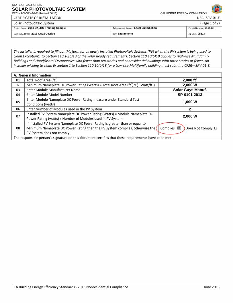
CERTIFICATE OF INSTALLATION NRCI‐SPV‐01‐E Solar Photovoltaic System (Page 1 of 2) Project Name: 2013 CALBO Training Sample Enforcement Agency: Local Jurisdiction Permit Number: 010113
Dwelling Address: 2013 CALBO Drive City Sacramento Zip Code 95814
CA Building Energy Efficiency Standards ‐ 2013 Nonresidential Compliance June 2013
The installer is required to fill out this form for all newly installed Photovoltaic Systems (PV) when the PV system is being used to claim Exception1 to Section 110.10(b)1B of the Solar Ready requirements. Section 110.10(b)1B applies to High‐rise Multifamily Buildings and Hotel/Motel Occupancies with fewer than ten stories and nonresidential buildings with three stories or fewer. An installer wishing to claim Exception 1 to Section 110.10(b)1B for a Low‐rise Multifamily building must submit a CF2R—SPV‐01‐E. A. General Information 01 Total Roof Area (ft2) 2,000 ft2 02. Minimum Nameplate DC Power Rating (Watts) = Total Roof Area (ft2) x (1 Watt/ft2) 2,000 W 03 Enter Module Manufacturer Name Solar Guys Manuf. 04 Enter Module Model Number SP-0101-2013
05 Enter Module Nameplate DC Power Rating measure under Standard Test Conditions (watts)
1,000 W
06 Enter Number of Modules used in the PV System 2
07 Installed PV System Nameplate DC Power Rating (Watts) = Module Nameplate DC Power Rating (watts) x Number of Modules used in PV System
2,000 W
08 If Installed PV System Nameplate DC Power Rating is greater than or equal to Minimum Nameplate DC Power Rating then the PV system complies, otherwise the PV System does not comply.
Complies ⌧ Does Not Comply
The responsible person's signature on this document certifies that these requirements have been met.

STATE OF CALIFORNIA
SOLAR WATER HEATING SYSTEMS CEC-NRCI-STH-01-E (Revised 06/13) CALIFORNIA ENERGY COMMISSION
CERTIFICATE OF INSTALLATION NRCI‐STH‐01‐E Solar Water Heating Systems (Page 1 of 2)Project Name: Enforcement Agency: Permit Number:
Project Address: City: Zip Code:
CA Building Energy Efficiency Standards ‐ 2013 Nonresidential Compliance June 2013
A. SOLAR WATER HEATING SYSTEMS
01 Manufacturer Name
02 Model Number
03 SRCC Certification Number
04 Solar Savings Fraction (annual average value)
05 # of Collectors in System
06 Collector Size (Square Footage)
07 Total Storage Volume (gallons)
08 Solar System Collector Orientation
09 Solar System Collector Tilt The responsible person’s signature on this Certificate of Installation indicates the system identified on this Certificate has complied with all applicable requirements specified in this Table. B. SRCC OG‐100 CERTIFIED COLLECTORS The installed system shall meet the following eligibility criteria: 01 System is installed at the same orientation as modeled.02 System is installed at the same tilt as modeled.
03 The system shall have the same collectors, pumps, controls, storage tank and backup water heater fuel type as the rated condition.
04 The collectors are located in a position that is not shaded by adjacent buildings or trees. 05 Backup Storage tanks are insulated with either an internal R‐12 (labeled on tank) or external R‐16 The responsible person’s signature on this Certificate of Installation indicates the system identified on this Certificate has complied with all applicable requirements specified in this Table.
C. SIZING COMPLIANCE WITH MULTIFAMILY PRESCRIPTIVE REQUIREMENTS:01 For climate zones 1 through 9 only ‐ the solar system has an annual solar savings fraction of 0.2 02 For climate zones 10 through 16 only – the solar system has an annual solar savings fraction of 0.35 The responsible person’s signature on this Certificate of Installation indicates the system identified on this Certificate has complied with all applicable requirements specified in this Table.
D. MANDATORY MEASURES FOR SOLAR WATER HEATING SYSTEMS
01 For Multifamily, Hotel and Motels backup storage tanks for solar water‐heating systems have R‐12 external insulation or R‐16 internal insulation where the internal insulation R‐value indicated on the exterior of the tank. (§150.0(j)1B).
02 All domestic hot water piping (including solar) shall be insulated (§150(j)2A) or (§120.3).
03 Solar water‐heating system and/or/collectors are certified by the Solar Rating and Certification Corporation. (§150.0(n)).
The responsible person’s signature on this Certificate of Installation indicates the system identified on this Certificate has complied with all applicable requirements specified in this Table.

C A L I F O R N I A E N E R G Y C O M M I S S I O N19
MECH Acceptance Testing2008 – §125
• Testing mandatory if equip.
2013 – §120.5• New tests added for:
installed for:Outdoor air ventilation
Supply air temp. reset cont.
Water cooled chillers / d t t lAir economizers
Demand controls vent.
w/condenser reset controls
EMCS
• Identified as “NRCA MCH”Supply fan variable flow cont.
Thermal energy storage
• Identified as “NRCA-MCH”
• Must be performed by Certified Mechanical
• Indentified as “MECH-A”Certified Mechanical Acceptance Test Technician (CMATT)

C A L I F O R N I A E N E R G Y C O M M I S S I O N20
§120.5 and the Plans ExaminerExaminer
• Still verify req. Acceptance Tests onAcceptance Tests on NRCC-MCH-01
NRCA-MCH-16A (supply air reset)
NRCA-MCH-17A ( hill d t)(chiller condenser reset)
NRCA-MCH-18A (ECMS)
• Form must be incorporated onto plans * Form must be registered starting 1/1/15

STATE OF CALIFORNIA
MECHANICAL SYSTEMS CEC-NRCC-MCH-01-E (Revised 06/13) CALIFORNIA ENERGY COMMISSION
CERTIFICATE OF COMPLIANCE NRCC‐MCH‐01‐E Mechanical Systems (Page 2 of 4) Project Name: 2013 CALBO Training Sample Date Prepared: 01/01/14
CA Building Energy Efficiency Standards ‐ 2013 Nonresidential Compliance June 2013
MECHANICAL HVAC ACCEPTANCE FORMS (check box for required forms) Designer: This form is to be used by the designer and attached to the plans. Listed below are all the acceptance tests for HVAC systems. The designer is required to check the applicable boxes for all acceptance tests that apply and list all equipment that requires an acceptance test. All equipment of the same type that requires a test, list the equipment description and the number of systems. Installing Contractor: The contractor who installed the equipment is responsible to either conduct the acceptance test them self or have a qualified entity run the test for them. If more than one person has responsibility for the acceptance testing, each person shall sign and submit the Certificate of Acceptance applicable to the portion of the construction or installation for which they are responsible. The following tests require a Enforcement Agency: Plancheck – The NRCC‐MCH‐01‐E form is not considered a completed form and is not to be accepted by the building department unless the correct boxes are checked. Inspector ‐ Before occupancy permit is granted all newly installed process systems must be tested to ensure proper operations.
Test Description MCH‐12A MCH‐13A MCH‐14A MCH‐15A MCH‐16A MCH‐17A MCH‐18A Equipment Requiring Testing or Verification
# of units
Fault Detection & Diagnostics for DX
Units
Automatic Fault Detection &
Diagnostics for Air & Zone
Distributed Energy Storage DX AC
Systems
Thermal Energy Storage (TES)
Systems
Supply Air Temperature Reset
Controls
Condenser Water Reset Controls
ECMS
Reset Controls 5
⌧
Chillers 10 ⌧
ECMS 2 ⌧

C A L I F O R N I A E N E R G Y C O M M I S S I O N21
§120.5 and the Plans Examiner contExaminer cont.
• All HVAC units/controls and req. acceptance test must b ifi d th NRCC MCH 01 fbe verified on the NRCC-MCH-01 form
• Frequently req. test include:Outdoor air ventilation (NRCA-MCH-02)
Single zone unitary A/C and HP controls (NRCA-MCH-03)
Duct leakage (NRCA-MCH-04)
Economizer controls (NRCA-MCH-05)
DCV (NRCA-MCH-06)

C A L I F O R N I A E N E R G Y C O M M I S S I O N22
§120.5 and the Field InspectorInspector
• At Final, still verify req. A t fAcceptance forms
Refer to NRCC-MCH-01 form
• Verify Acceptance testing is performed by CMATT when requiredrequired
Identify signature in Declaration Statement
• Verify all Acceptance forms are registered starting 1/1/15

STATE OF CALIFORNIA
Supply Air Temperature Reset Controls Acceptance CEC-NRCA-MCH-16-F (Revised 06/13) CALIFORNIA ENERGY COMMISSION
CERTIFICATE OF ACCEPTANCE NRCA‐MCH‐16‐F Supply Air Temperature Reset Controls Acceptance (Page 1 of 2)Project Name: 2013 CALBO Training Sample Enforcement Agency: Local Jurisdiction Permit Number: 010113
Project Address: 2013 CALBO Drive City: Sacramento Zip Code: 95814
CA Building Energy Efficiency Standards ‐ 2013 Nonresidential Compliance June 2013
Note: Submit one Certificate of Acceptance for each system that must demonstrate compliance.
Enforcement Agency Use: Checked by/Date
Intent: Verify that the supply air temperature modulates to meet system temperature setpoint(s).
Construction Inspection
1. Supporting documentation needed to perform test may include, but is not limited to:
a. As‐built and/or Design Documents, including Mechanical Equipment Schedules and control schedules.
b.
2013 Building Energy Efficiency Standards Nonresidential Compliance Manual (NA7.5.15 Supply Air Temperature Reset Controls Acceptance At‐A‐Glance).
c. 2013 Building Energy Efficiency Standards Nonresidential Appendix (Section NA7).
2. Instrumentation to perform test includes, but is not limited to:
a. Hand‐held temperature sensor Date of calibration: 01/01/14 (must be within one year)
3. Installation:
Check the appropriate box:
⌧ The supply air temperature reset controls are installed per the requirements of the 2013 Building Energy Efficiency Standards section 140.4(f): Multi‐zone systems shall include controls that automatically reset supply‐air temperatures:
(1) In response to representative building loads or to outdoor air temperature; and
(2) By at least 25 percent of the difference between the design supply‐air temperature and the design room air temperature.
⌧ An exception is taken to this requirement (one of the following must be true; acceptance test is not needed):
Zones served by space‐conditioning systems in which at least 75 percent of the energy for reheating, or providing warm air in mixing systems, is provided from a site‐recovered or site‐solar energy source.
Where supply‐air temperature reset would increase overall building energy use.
Zones in which specific humidity levels are required to satisfy exempt process loads. Computer rooms or spaces with only IT equipment are not exempt process loads.
Zones with a peak supply air quantity of 300 cfm or less.
The system has controls to prevent reheat, recool, and simultaneous cooling and heating.
4. Document that all system air temperature sensors are factory or field calibrated or perform field check (check a or b):
a. Factory calibrated, or Field‐calibrated by TAB technician, commissioning agent, or other.
⌧ Calibration complete, all sensors within 2% of calibrated reference sensor (provide supporting documentation, e.g. a copy of TAB calibration results).
b. I have performed a field check using a calibrated temperature standard (i.e. device that has been calibrated within the last 12 months).
� Check complete, all air temperature sensors within 2% of calibrated reference sensor (provide supporting documentation,
including results from system air sensors and calibrated reference standard).
5. Document current supply air temperature: 75 °F Notes:

STATE OF CALIFORNIA
Supply Air Temperature Reset Controls Acceptance CEC-NRCA-MCH-16-F (Revised 06/13) CALIFORNIA ENERGY COMMISSION
CERTIFICATE OF ACCEPTANCE NRCA‐MCH‐16‐F Supply Air Temperature Reset Controls Acceptance (Page 2 of 2)Project Name: 2013 CALBO Training Sample Enforcement Agency: Local Jurisdiction Permit Number: 010113
Project Address: 2013 CALBO Drive City: Sacramento Zip Code: 95814
CA Building Energy Efficiency Standards ‐ 2013 Nonresidential Compliance June 2013
A. Functional Testing
Check to make sure that chilled / hot water coils, if used, are not already fully open and calling for maximum cooling / heating. If this is the case, reverse Steps 1 and 2 and/or change the set point range as necessary to conduct this test.
Reset control parameter is (circle one): Outside air temperature, Zone or return air temperature, Zones calling for heating or cooling, or Other ______________.
Step 1: During occupied mode, adjust the reset control parameter to decrease the supply air temperature (to the lower supply temperature limit).
a. Supply air temperature controls modulate as intended. Y / N
b. Actual supply air temperature decreases to meet the new set point within +/‐ 2°F. Y / N
c. Supply air temperature stabilizes within 15 minutes. Y / N
Supply air temperature set point: _ 80__ ° F Actual supply air temperature: __82__ ° F
Step 2: During occupied mode, adjust the reset control parameter to increase the supply air temperature (to the upper supply temperature limit).
a. Supply air temperature controls modulate as intended. Y / N
b. Actual supply air temperature increases to meet the new set point within +/‐ 2°F. Y / N
c. Supply air temperature stabilizes within 15 minutes. Y / N
Supply air temperature set point: _ 75 _ ° F Actual supply air temperature: _ 73 __ ° F
Step 3: Restore reset control parameter to automatic control.
a. Supply air temperature controls modulate as intended. Y / N
b. Actual supply air temperature changes to meet the new set point within +/‐ 2°F. Y / N
c. Supply air temperature stabilizes within 15 minutes. Y / N
Supply air temperature set point: _ 78__ ° F Actual supply air temperature: _ 76__ ° F
B. Evaluation :
⌧ PASS: All Construction Inspection responses are complete and Functional Testing Results are all circled YES.
Notes:

STATE OF CALIFORNIA
CONDENSER WATER SUPPLY TEMPERATURE RESET CONTROLS ACCEPTANCE CEC-NRCA-MCH-17-F (Revised 06/13) CALIFORNIA ENERGY COMMISSION
CERTIFICATE OF ACCEPTANCE NRCA‐MCH‐17‐F Condenser Water Supply Temperature Reset Controls Acceptance (Page 1 of 2)Project Name: Enforcement Agency: Permit Number:
Project Address: City: Zip Code:
CA Building Energy Efficiency Standards ‐ 2013 Nonresidential Compliance June 2013
Note: Submit one Certificate of Acceptance for each system that must demonstrate compliance.
Enforcement Agency Use: Checked by/Date
Intent: Ensure that the condenser water supply temperature is automatically reset as indicated in the control sequence(s).
Construction Inspection
1. Supporting documentation needed to perform test may include, but is not limited to:
a. As‐built and/or Design Documents, including Mechanical Equipment Schedules and control schedules.
b.
2013 Building Energy Efficiency Standards Nonresidential Compliance Manual (NA7.5.65 Condenser Water Supply Temperature Reset Controls Acceptance At‐A‐Glance).
c. Building Energy Efficiency Standards Nonresidential Appendix (Section NA7).
2. Instrumentation to perform test includes, but is not limited to:
a. Hand‐held temperature sensor ______________Date of calibration (must be within 1 year)
b. Hand‐held relative humidity or wet‐bulb temperature sensor / psychrometer______________Date of calibration (must be within 1 year)
3. Installation Verification:
� Check if the condenser water supply system and control system are installed per the system design, as documented on the building plans or as‐builts.
� Check if condenser water supply temperature control sequence, including condenser water supply high and low limits, are available and documented in the building documents.
� Check if all cooling tower fan motors are operational, and cooling tower fan speed controls (e.g. VSDs) are installed, operational, and connected to cooling tower fan motors per OEM start‐up manuals and sequence of operation.
� Check if cooling tower fan control sequence, including tower design wetbulb temperature and approach, are available and documented in the building documents.
� Check if the following temperature sensors are installed per plans: outdoor air drybulb and wetbulb, entering condenser water, and leaving chilled water. Note any discrepancies:
4. Document that all system temperature and relative humidity sensors are factory or field calibrated or perform field check (check one of the following):
�
Sensors are calibrated by others. Factory calibrated, or Field‐calibrated by TAB technician, commissioning agent, or other.
Calibration complete, all sensors within 2% of calibrated reference sensor (provide supporting documentation, i.e. a copy of TAB calibration results).
� I have performed a field check using a calibrated temperature standard (i.e. device that has been calibrated within the last 12 months).
Check complete, all sensors within 2% of calibrated reference sensor (provide supporting documentation, including results from system sensors and calibrated reference standard).
5. From the control system, or using temperature sensors, document the following:
Outdoor air drybulb temperature ________ ° F Outdoor air wetbulb temperature ________ ° F
Entering condenser water temperature ________ ° F Leaving chilled water temperature ________ ° F

STATE OF CALIFORNIA
CONDENSER WATER SUPPLY TEMPERATURE RESET CONTROLS ACCEPTANCE CEC-NRCA-MCH-17-F (Revised 06/13) CALIFORNIA ENERGY COMMISSION
CERTIFICATE OF ACCEPTANCE NRCA‐MCH‐17‐F Condenser Water Supply Temperature Reset Controls Acceptance (Page 2 of 2)Project Name: Enforcement Agency: Permit Number:
Project Address: City: Zip Code:
CA Building Energy Efficiency Standards ‐ 2013 Nonresidential Compliance June 2013
A. Functional Testing
The system cooling load must be sufficiently high to run the test. If necessary, artificially increase the cooling / evaporator load to perform the functional tests. If necessary, reverse Steps 1 & 2 in the test based on atmospheric conditions and building loads.
EXEMPTION: If the control sequence differs significantly from that implied by the tests, and / or has already been tested during the building commissioning process, attach a description of the control sequence, a description of the tests that were done to verify the system operates according to the sequence, the test results, and a plot of any associated trend data.
Reset control parameter is (circle one): Outside air wet‐bulb temperature, Load signal from chiller, Condenser water & chilled water temperatures, or Other _____________________.
Step 1: Adjust the reset control parameter to decrease the condenser water temperature (toward the lower supply temperature limit).
a. Condenser water temperature controls modulate as intended. Y / N
b. Actual condenser water supply temperature decreases to meet new set point within + / ‐ 2°F. Y / N
c. Cooling tower fan(s) stage properly and/or adjust speed accordingly to meet lower set point. Y / N
d. Chiller load amps decrease. Y / N
Step 2: Adjust the reset control parameter to increase the condenser water temperature (toward the upper supply temperature limit).
a. Condenser water temperature controls modulate as intended. Y / N
b. Actual condenser water supply temperature increases to meet new set point within + / ‐ 2°F. Y / N
c. Cooling tower fan(s) stage properly and/or adjust speed accordingly to meet upper set point. Y / N
d. Chiller load amps increase. Y / N
Step 3: Restore reset control parameter to automatic control.
a. Condenser water temperature controls modulate as intended. Y / N
b. Actual condenser water supply temperature changes to meet new set point within + / ‐ 2°F. Y / N
c. Cooling tower fan(s) stage properly and/or adjust speed accordingly to meet set point. Y / N
B. Evaluation:
� PASS: All Construction Inspection responses are complete and Functional Testing Results are all circled YES.
Notes:

STATE OF CALIFORNIA
ENERGY MANAGEMENT CONTROL SYSTEM ACCEPTANCE CEC-NRCA-MCH-18-F (Revised 06/13) CALIFORNIA ENERGY COMMISSION
CERTIFICATE OF ACCEPTANCE NRCA‐MCH‐18‐F Energy Management Control System Acceptance (Page 1 of 1)Project Name: Enforcement Agency: Permit Number:
Project Address: City: Zip Code:
CA Building Energy Efficiency Standards ‐ 2013 Nonresidential Compliance June 2013
Note: Submit one Certificate of Acceptance for each system that must demonstrate compliance.
Enforcement Agency Use: Checked by/Date:
Intent:
The purpose of this acceptance test is to help ensure the central control system, when installed, is properly installed and configured and capable of meeting the applicable requirements of Title 24 Part 6. The EMCS is a complex, highly customized control system with many opportunities for installation and programming problems. Obviously it is important to identify, diagnose, and resolve these problems. This acceptance test can help assist with this effort.
A. Construction Inspection
Prior to functional testing and conducting other acceptance tests that rely on the EMCS: � Factory start‐up and check‐out completed � Point‐to‐point verification completed � I/O point lists available � Sequence of operations of each system are programmed � Written sequences are available � Input sensors are calibrated
B. Functional Testing Results
Conduct the following verification checks to validate the functionality of the EMCS: 1. Verify the control graphics represent the system configuration 2. Verify control points are properly mapped to the graphics screen 3. Raise and lower a sampling of space temperature setpoints in the software and verify the system responds
appropriately 4. Verify the time‐of‐day start‐up and shut‐down function initiates a proper system response 5. Verify trending capabilities by establishing trend logs for a sampling of control points 6. Verify alarm conditions are monitored 7. Verify the EMCS panel is installed on an emergency power circuit or has adequate battery back‐up
Y / N Y / N Y / N
Y / N Y / N Y / N Y / N
C. Testing Results PASS / FAIL
Test passes if all Construction Inspection boxes are checked and all Functional Testing results are ‘Y’ � �

C A L I F O R N I A E N E R G Y C O M M I S S I O N23
§120.5 and the Field Inspector contInspector cont.
• Occupancy permit shall not be issued until all req. A t t t /f ifi dAcceptance tests/forms are verified
• \
Refer to NRCC-MCH-01 form
• When ATTCPs are interim approved, CMATT will be req. for only 8 tests
Listed in §10-103-B
• CMATT testing will be req. for ALL acceptance tests once ATTCPs are fully approved
Check website for approved ATTCPs

C A L I F O R N I A E N E R G Y C O M M I S S I O N24
Covered Processes2008 – §126
• Requirements for
2013 – §120.6• Refrigerated warehouseRequirements for
refrigerated warehouses ≥ 3,000 ft2:
Refrigerated warehouse reqs. updated
Acceptance testing req.Insulation (walls, roof, etc.)
Evaporators
p g q
• Covered processes added:Commercial refrigerationp
Condensers
Compressors
Commercial refrigeration
Enclosed parking garages
Process boilersCompressors Process boilers
Compressed air systems

C A L I F O R N I A E N E R G Y C O M M I S S I O N25
Covered Processes cont.• Commercial refrigeration reqs. in §120.6(b)
Applicable to retail food stores with CFA ≥ 8,000 ft2 that have refrigerationg
• Enclosed parking garages reqs. in §120.6(c)Applicable if total design exhaust rate ≥ 10,000 CFMpp g ,Acceptance testing req. for ventilation
• Process boiler reqs. in §120.6(d)Process boiler reqs. in §120.6(d)Applicability based on boiler capacity (Btu/h)
• Compressed air system reqs. in §120.6(e)Compressed air system reqs. in §120.6(e)Applicable to compressors with HP ≥ 25Acceptance testing req. for compressor and controls

2013 Building Energy Efficiency Standards Page 118
SECTION 120.6 – MANDATORY REQUIREMENTS FOR COVERED PROCESSES
an approved Acceptance Test Technician Certification Provider. The CMATT shall complete all Certificate of Acceptance documentation in accordance with the applicable requirements in Section 10-103(a)4.
NOTE: Authority cited: Sections 25402, 25402.1, and 25213, Public Resources Code. Reference: Sections 25007, 25402(a)-(b), 25402.1, 25402.4, 25402.5, 25402.8 and 25910, Public Resources Code.
SECTION 120.6 – MANDATORY REQUIREMENTS FOR COVERED PROCESSES (a) Mandatory Requirements for Refrigerated Warehouses
Refrigerated Warehouses that are greater than or equal to 3,000 square feet shall meet the requirements of Subsections 1, 2, 3, 6 and 7 of Section 120.6(a).
Refrigerated Spaces that are less than 3,000 square feet shall meet the requirements of the Appliance Efficiency Regulations for walk-in coolers or freezers contained in the Appliance Efficiency Regulations (California Code of Regulations, Title 20, Sections 1601 through 1608).
Refrigerated Spaces that (i) comprise a total of 3,000 square feet or more; and (ii) are collectively served by the same refrigeration system compressor(s) and condenser(s) shall meet the requirements of Subsections 4, 5 and 7 of Section 120.6(a).
1. Insulation Requirements. Exterior surfaces of refrigerated warehouses shall be insulated at least to the R-values in TABLE 120.6-A.
TABLE 120.6-A REFRIGERATED WAREHOUSE INSULATION SPACE SURFACE MINIMUM R-VALUE (°F·hr·sf/Btu)
Freezers
Roof/Ceiling R-40
Wall R-36
Floor R-35
Floor with all heating from productive refrigeration capacity1
R-20
Coolers Roof/Ceiling R-28
Wall R-28
1. All underslab heating is provided by a heat exchanger that provides refrigerant subcooling or other means that result in productive refrigeration capacity on the associated refrigerated system.
2. Underslab heating. Electric resistance heat shall not be used for the purposes of underslab heating.
EXCEPTION to Section 120.6(a)2: Underslab heating systems controlled such that the electric resistance heat is thermostatically controlled and disabled during the summer on-peak period defined by the local electric utility.
3. Evaporators. New fan-powered evaporators used in coolers and freezers shall conform to the following:
A. Single phase fan motors less than 1 hp and less than 460 Volts in newly installed evaporators shall be electronically commutated motors or shall have a minimum motor efficiency of 70 percent when rated in accordance with NEMA Standard MG 1-2006 at full load rating conditions.
B. Evaporator fans served either by a suction group with multiple compressors, or by a single compressor with variable capacity capability shall be variable speed and the speed shall be controlled in response to space temperature or humidity.
EXCEPTION 1 to Section 120.6(a)3B: Addition, alteration or replacement of less than all of the evaporators in an existing refrigerated space that does not have speed-controlled evaporators.

2013 Building Energy Efficiency Standards Page 119
SECTION 120.6 – MANDATORY REQUIREMENTS FOR COVERED PROCESSES
EXCEPTION 2 to Section 120.6(a)3B: Coolers within refrigerated warehouses that maintain a Controlled Atmosphere for which a licensed engineer has certified that the types of products stored will require constant operation at 100 percent of the design airflow.
EXCEPTION 3 to Section 120.6(a)3B: Areas within refrigerated warehouses that are designed solely for the purpose of quick chilling/freezing of products (space with design cooling capacities of greater than 240 Btu/hr-ft² (2 tons per 100 ft²)).
C. Evaporator fans served by a single compressor that does not have variable capacity shall utilize controls to reduce airflow by at least 40 percent for at least 75 percent of the time when the compressor is not running.
EXCEPTION to Section 120.6(a)3C: Areas within refrigerated warehouses that are designed solely for the purpose of quick chilling/freezing of products (space with design cooling capacities of greater than 240 Btu/hr-ft² (2 tons per 100 ft²)).
4. Condensers. New fan-powered condensers on new refrigeration systems shall conform to the following:
A. Design saturated condensing temperatures for evaporative-cooled condensers and water-cooled condensers served by fluid coolers or cooling towers shall be less than or equal to:
i. The design wetbulb temperature plus 20°F in locations where the design wetbulb temperature is less than or equal to 76°F; or
ii. The design wetbulb temperature plus 19°F in locations where the design wetbulb temperature is between 76°F and 78°F; or
iii. The design wetbulb temperature plus 18°F in locations were the design wetbulb temperature is greater than or equal to 78°F.
EXCEPTION to Section 120.6(a)4A: Compressors and condensers on a refrigeration system for which more than 20 percent of the total design refrigeration cooling load is for quick chilling or freezing, or process refrigeration cooling for other than a refrigerated space.
B. Design saturated condensing temperatures for air-cooled condensers shall be less than or equal to the design drybulb temperature plus 10°F for systems serving freezers and shall be less than or equal to the design drybulb temperature plus 15°F for systems serving coolers.
EXCEPTION 1 to Section 120.6(a)4B: Condensing units with a total compressor horsepower less than 100 HP.
EXCEPTION 2 to Section 120.6(a)4B: Compressors and condensers on a refrigeration system for which more than 20 percent of the total design refrigeration cooling load is for quick chilling or freezing, or process refrigeration cooling for other than a refrigerated space.
C. All condenser fans for evaporative-cooled condensers or fans on cooling towers or fluid coolers shall be continuously variable speed, and the condensing temperature control system shall control the speed of all fans serving a common condenser high side in unison. The minimum condensing temperature setpoint shall be less than or equal to 70°F.
D. All condenser fans for air-cooled condensers shall be continuously variable speed and the condensing temperature or pressure control system shall control the speed of all condenser fans serving a common condenser high side in unison. The minimum condensing temperature setpoint shall be less than or equal to 70°F.
E. Condensing temperature reset. The condensing temperature set point of systems served by air-cooled condensers shall be reset in response to ambient drybulb temperature. The condensing temperature set point of systems served by evaporative-cooled condensers or water-cooled condensers (via cooling towers or fluid coolers) shall be reset in response to ambient wetbulb temperatures.
EXCEPTION to Section 120.6(a)4E: Condensing temperature control strategies approved by the Executive Director that have been demonstrated to provide at least equal energy savings.

2013 Building Energy Efficiency Standards Page 120
SECTION 120.6 – MANDATORY REQUIREMENTS FOR COVERED PROCESSES
F. Fan-powered condensers shall meet the condenser efficiency requirements listed in TABLE 120.6-B. Condenser efficiency is defined as the Total Heat of Rejection (THR) capacity divided by all electrical input power including fan power at 100 percent fan speed, and power of spray pumps for evaporative condensers.
G. Air-cooled condensers shall have a fin density no greater than 10 fins per inch.
EXCEPTION to Section 120.6(a)4G: Micro-channel condensers.
TABLE 120.6-B FAN-POWERED CONDENSERS – MINIMUM EFFICIENCY REQUIREMENTS CONDENSER TYPE REFRIGERANT TYPE MINIMUM EFFICIENCY RATING CONDITION
Outdoor Evaporative-Cooled with THR Capacity > 8,000 MBH
All 350 Btuh/Watt 100°F Saturated Condensing
Temperature (SCT), 70°F Outdoor Wetbulb Temperature
Outdoor Evaporative-Cooled with THR Capacity < 8,000 MBH and Indoor Evaporative-Cooled
All 160 Btuh/Watt
Outdoor Air-Cooled Ammonia 75 Btuh/Watt 105°F Saturated Condensing
Temperature (SCT), 95°F Outdoor Drybulb Temperature Halocarbon 65 Btuh/Watt
Indoor Air-Cooled All Exempt
5. Compressors. Compressor systems utilized in refrigerated warehouses shall conform to the following:
A. Compressors shall be designed to operate at a minimum condensing temperature of 70°F or less.
B. New open-drive screw compressors in new refrigeration systems with a design saturated suction temperature (SST) of 28°F or lower that discharges to the system condenser pressure shall control compressor speed in response to the refrigeration load.
EXCEPTION 1 to Section 120.6(a)5B: Refrigeration plants with more than one dedicated compressor per suction group.
EXCEPTION 2 to Section 120.6(a)5B: Compressors and condensers on a refrigeration system for which more than 20 percent of the total design refrigeration cooling load is for quick chilling or freezing, or process refrigeration cooling for other than a refrigerated space.
C. New screw compressors with nominal electric motor power greater than 150 HP shall include the ability to automatically vary the compressor volume ratio (Vi) in response to operating pressures.
6. Infiltration Barriers. Passageways between freezers and higher-temperature spaces, and passageways between coolers and non-refrigerated spaces, shall have an infiltration barrier consisting of strip curtains, an automatically-closing door, or an air curtain designed by the manufacturer for use in the passageway and temperature for which it is applied.
EXCEPTION 1 to Section 120.6(a)6: Openings with less than 16 ft2 of opening area.
EXCEPTION 2 to Section 120.6(a)6: Dock doorways for trailers.
7. Refrigeration System Acceptance. Before an occupancy permit is granted for a new refrigerated warehouse, or before a new refrigeration system serving a refrigerated warehouse is operated for normal use, the following equipment and systems shall be certified as meeting the Acceptance Requirements for Code Compliance, as specified by the Reference Nonresidential Appendix NA7. A Certificate of Acceptance shall be submitted to the enforcement agency that certifies that the equipment and systems meet the acceptance requirements:
A. Electric resistance underslab heating systems shall be tested in accordance with NA7.10.1.
B. Evaporators fan motor controls shall be tested in accordance with NA7.10.2.
C. Evaporative condensers shall be tested in accordance with NA7.10.3.1.

2013 Building Energy Efficiency Standards Page 121
SECTION 120.6 – MANDATORY REQUIREMENTS FOR COVERED PROCESSES
D. Air-cooled condensers shall be tested in accordance with NA7.10.3.2.
E. Variable speed compressors shall be tested in accordance with NA7.10.4.
(b) Mandatory Requirements for Commercial Refrigeration
Retail food stores with 8,000 square feet or more of conditioned area, and that utilize either: refrigerated display cases, or walk-in coolers or freezers connected to remote compressor units or condensing units, shall meet the requirements of Subsections 1 through 4.
1. Condensers serving refrigeration systems. Fan-powered condensers shall conform to the following requirements:
A. All condenser fans for air-cooled condensers, evaporative-cooled condensers, air or water-cooled fluid coolers or cooling towers shall be continuously variable speed, with the speed of all fans serving a common condenser high side controlled in unison.
B. The refrigeration system condenser controls for systems with air-cooled condensers shall use variable-setpoint control logic to reset the condensing temperature setpoint in response to ambient drybulb temperature.
C. The refrigeration system condenser controls for systems with evaporative-cooled condensers shall use variable-setpoint control logic to reset the condensing temperature setpoint in response to ambient wetbulb temperature.
EXCEPTION to Section 120.6(b)1B and C: Condensing temperature control strategies approved by the Executive Director that have been demonstrated to provide equal energy savings.
D. The minimum condensing temperature setpoint shall be less than or equal to 70°F.
E. Fan-powered condensers shall meet the specific efficiency requirements listed in Table 120.6-C.
TABLE 120.6-C FAN-POWERED CONDENSERS –SPECIFIC EFFICIENCY REQUIREMENTS CONDENSER TYPE MINIMUM SPECIFIC EFFICIENCYa RATING CONDITION
Evaporative-Cooled 160 Btuh/W 100°F Saturated Condensing Temperature (SCT), 70°F Entering Wetbulb Temperature
Air-Cooled 65 Btuh/W 105°F Saturated Condensing Temperature (SCT), 95°F Entering Drybulb Temperature
a See Section 100.1 for definition of condenser specific efficiency.
EXCEPTION 1 to Section 120.6(b)1E: Condensers with a Total Heat Rejection capacity of less than 150,000 Btuh at the specific efficiency rating condition.
EXCEPTION 2 to Section 120.6(b)1E: Stores located in Climate Zone 1.
EXCEPTION 3 to Section 120.6(b)1E: Existing condensers that are reused for an addition or alteration.
F. Air-cooled condensers shall have a fin density no greater than 10 fins per inch.
EXCEPTION 1 to Section 120.6(b)1F: Micro-channel condensers.
EXCEPTION 2 to Section 120.6(b)1F: Existing condensers that are reused for an addition or alteration.
EXCEPTION to Section 120.6(b)1: New condensers replacing existing condensers when the attached compressor system Total Heat of Rejection does not increase and less than 25 percent of both the attached compressors and the attached display cases are new.
2. Compressor Systems. Refrigeration compressor systems and condensing units shall conform to the following requirements.

2013 Building Energy Efficiency Standards Page 122
SECTION 120.6 – MANDATORY REQUIREMENTS FOR COVERED PROCESSES
A. Compressors and multiple-compressor suction groups shall include control systems that use floating suction pressure logic to reset the target saturated suction temperature based on the temperature requirements of the attached refrigeration display cases or walk-ins.
EXCEPTION 1 to Section 120.6(b)2A: Single compressor systems that do not have continuously variable capacity capability.
EXCEPTION 2 to Section 120.6(b)2A: Suction groups that have a design saturated suction temperature of 30°F or higher, or suction groups that comprise the high stage of a two-stage or cascade system or that primarily serve chillers for secondary cooling fluids.
B. Liquid subcooling shall be provided for all low temperature compressor systems with a design cooling capacity equal or greater than 100,000 Btu/hr with a design saturated suction temperature of -10°F or lower, with the subcooled liquid temperature maintained continuously at 50°F or less at the exit of the subcooler, using compressor economizer port(s) or a separate medium or high temperature suction group operating at a saturated suction temperature of 18°F or higher.
EXCEPTION to Section 120.6(b)2B: Low temperature cascade systems that condense into another refrigeration system rather than condensing to ambient temperature.
EXCEPTION to Section 120.6(b)2: Existing compressor systems that are reused for an addition or alteration.
3. Refrigerated Display Cases. Lighting in refrigerated display cases, and lights on glass doors installed on walk-in coolers and freezers shall be controlled by one of the following:
A. Automatic time switch controls to turn off lights during non-business hours. Timed overrides for any line-up or walk-in case may only be used to turn the lights on for up to one hour. Manual overrides shall time-out automatically to turn the lights off after one hour.
B. Motion sensor controls on each case that reduce display case lighting power by at least 50 percent within 30 minutes after the area near the case is vacated.
EXCEPTION to Section 120.6(b)3: Stores which are normally open for business 140 hours or more per week.
4. Refrigeration Heat Recovery.
A. HVAC systems shall utilize heat recovery from refrigeration system(s) for space heating, using no less than 25 percent of the sum of the design Total Heat of Rejection of all refrigeration systems that have individual Total Heat of Rejection values of 150,000 Btu/h or greater at design conditions.
EXCEPTION 1 to Section 120.6(b)4A: Stores located in Climate Zone 15.
EXCEPTION 2 to Section 120.6(b)4A: HVAC systems or refrigeration systems that are reused for an addition or alteration.
B. The increase in hydrofluorocarbon refrigerant charge associated with refrigeration heat recovery equipment and piping shall be no greater than 0.35 lbs per 1,000 Btu/h of heat recovery heating capacity.
(c) Mandatory Requirements for Enclosed Parking Garages. Mechanical ventilation systems for enclosed parking garages where the total design exhaust rate for the garage is greater than or equal to 10,000 cfm shall conform to all of the following:
1. Automatically detect contaminant levels and stage fans or modulate fan airflow rates to 50 percent or less of design capacity provided acceptable contaminant levels are maintained.
2. Have controls and/or devices that will result in fan motor demand of no more than 30 percent of design wattage at 50 percent of design airflow.
3. CO shall be monitored with at least one sensor per 5,000 ft2, with the sensor located in the highest expected concentration locations, with at least two sensors per proximity zone. A proximity zone is defined as an area that is isolated from other areas either by floor or other impenetrable obstruction.
4. CO concentration at all sensors is maintained at 25 ppm or less at all times.
5. The ventilation rate shall be at least 0.15 cfm/ft2 when the garage is scheduled to be occupied.

2013 Building Energy Efficiency Standards Page 123
SECTION 120.6 – MANDATORY REQUIREMENTS FOR COVERED PROCESSES
6. The system shall maintain the garage at negative or neutral pressure relative to other occupiable spaces when the garage is scheduled to be occupied.
7. CO sensors shall be:
A. Certified by the manufacturer to be accurate within plus or minus 5 percent of measurement.
B. Factory calibrated.
C. Certified by the manufacturer to drift no more than 5 percent per year.
D. Certified by the manufacturer to require calibration no more frequently than once a year.
E. Monitored by a control system. The system shall have logic that automatically checks for sensor failure by the following means. Upon detection of a failure, the system shall reset to design ventilation rates and transmit an alarm to the facility operators.
i. If any sensor has not been calibrated according to the manufacturer’s recommendations within the specified calibration period, the sensor has failed.
ii. During unoccupied periods the system compares the readings of all sensors, e.g. if any sensor is more than 15 ppm above or below the average of all sensors for longer than 4 hours, the sensor has failed.
iii. During occupied periods the system compares the readings of sensors in the same proximity zone, e.g. if the 30 minute rolling average for any sensor in a proximity zone is more than 15 ppm above or below the 30 minute rolling average for other sensor(s) in that proximity zone, the sensor has failed.
8. Parking Garage Ventilation System Acceptance. Before an occupancy permit is granted for a parking garage system subject to Section 120.6(c), the following equipment and systems shall be certified as meeting the Acceptance Requirements for Code Compliance, as specified by the Reference Nonresidential Appendix NA7. A Certificate of Acceptance shall be submitted to the enforcement agency that certifies that the equipment and systems meet the acceptance requirements specified in NA7.12.
EXCEPTION 1 to Section 120.6(c): Any garage, or portion of a garage, where more than 20 percent of the vehicles expected to be stored have non gasoline combustion engines.
EXCEPTION 2 to Section 120.6(c): Additions and alterations to existing garages where less than 10,000 cfm of new exhaust capacity is being added.
(d) Mandatory Requirements for Process Boilers
1. Combustion air positive shut-off shall be provided on all newly installed process boilers as follows:
A. All process boilers with an input capacity of 2.5 MMBtu/h (2,500,000 Btu/h) and above, in which the boiler is designed to operate with a non-positive vent static pressure.
B. All process boilers where one stack serves two or more boilers with a total combined input capacity per stack of 2.5 MMBtu/h (2,500,000 Btu/h).
2. Process boiler combustion air fans with motors 10 horsepower or larger shall meet one of the following for newly installed boilers:
A. The fan motor shall be driven by a variable speed drive; or
B. The fan motor shall include controls that limit the fan motor demand to no more than 30 percent of the total design wattage at 50 percent of design air volume.
3. Newly installed process boilers with an input capacity of 5 MMBtu/h (5,000,000 Btu/h) to 10 MMBtu/h (10,000,000 Btu/h) shall maintain excess (stack-gas) oxygen concentrations at less than or equal to 5.0 percent by volume on a dry basis over firing rates of 20 percent to 100 percent. Combustion air volume shall be controlled with respect to firing rate or measured flue gas oxygen concentration. Use of a common gas and combustion air control linkage or jack shaft is prohibited.
4. Newly installed process boilers with an input capacity greater than 10 MMBtu/h (10,000,000 Btu/h) shall maintain excess (stack-gas) oxygen concentrations at less than or equal to 3.0 percent by volume on a dry basis over firing rates of 20 percent to 100 percent. Combustion air volume shall be controlled with respect to

2013 Building Energy Efficiency Standards Page 124
SECTION 120.6 – MANDATORY REQUIREMENTS FOR COVERED PROCESSES
measured flue gas oxygen concentration. Use of a common gas and combustion air control linkage or jack shaft is prohibited.
(e) Mandatory Requirements for Compressed Air Systems. All new compressed air systems, and all additions or alterations of compressed air systems where the total combined online horsepower (hp) of the compressor(s) is 25 horsepower or more shall meet the requirements of Subsections 1 through 3. These requirements apply to the compressors and related controls that provide compressed air and do not apply to any equipment or controls that use or process the compressed air.
EXCEPTION to Section 120.6(e): Alterations of existing compressed air systems that include one or more centrifugal compressors.
1. Trim Compressor and Storage. The compressed air system shall be equipped with an appropriately sized trim compressor and primary storage to provide acceptable performance across the range of the system and to avoid control gaps. The compressed air system shall comply with Subsection A or B below:
A. The compressed air system shall include one or more variable speed drive (VSD) compressors. For systems with more than one compressor, the total combined capacity of the VSD compressor(s) acting as trim compressors must be at least 1.25 times the largest net capacity increment between combinations of compressors. The compressed air system shall include primary storage of at least one gallon per actual cubic feet per minute (acfm) of the largest trim compressor; or,
B. The compressed air system shall include a compressor or set of compressors with total effective trim capacity at least the size of the largest net capacity increment between combinations of compressors, or the size of the smallest compressor, whichever is larger. The total effective trim capacity of single compressor systems shall cover at least the range from 70 percent to 100 percent of rated capacity. The effective trim capacity of a compressor is the size of the continuous operational range where the specific power of the compressor (kW/100 acfm) is within 15 percent of the specific power at its most efficient operating point. The total effective trim capacity of the system is the sum of the effective trim capacity of the trim compressors. The system shall include primary storage of at least 2 gallons per acfm of the largest trim compressor.
EXCEPTION 1 to Section 120.6(e)1: Compressed air systems in existing facilities that are adding or replacing less than 50 percent of the online capacity of the system.
EXCEPTION 2 to Section 120.6(e)1: Compressed air systems that have been approved by the Energy Commission Executive Director as having demonstrated that the system serves loads for which typical air demand fluctuates less than 10 percent.
2. Controls. Compressed air systems with more than one compressor online, having a combined horsepower rating of more than 100 hp, must operate with a controller that is able to choose the most energy efficient combination of compressors within the system based on the current air demand as measured by a sensor.
3. Compressed Air System Acceptance. Before an occupancy permit is granted for a compressed air system subject to Section 120.6(e), the following equipment and systems shall be certified as meeting the Acceptance Requirements for Code Compliance, as specified by the Reference Nonresidential Appendix NA7. A Certificate of Acceptance shall be submitted to the enforcement agency that certifies that the equipment and systems meet the acceptance requirements specified in NA 7.13.

C A L I F O R N I A E N E R G Y C O M M I S S I O N26
§120.6 and the Plans E aminerExaminer
• Verify applicable Certificate of Compliance on plans
NRCC-PRC-02 (Garages)
NRCC-PRC-05 (Comm. Refrig.)
NRCC-PRC-10 (Comp. Air Sys.)
NRCC-PRC-11 (Boilers)
• Verify specifications match the l ( h i l h d lplans (mechanical schedules,
note blocks, etc.)* Forms must be registered starting 1/1/15

STATE OF CALIFORNIA
GARAGE EXHAUST CEC-NRCC-PRC-02-E (Revised 06/13) CALIFORNIA ENERGY COMMISSION
CERTIFICATE OF COMPLIANCE NRCC‐PRC‐02‐E Garage Exhaust (Page 1 of 1)Project Name: 2013 CALBO Training Sample Date Prepared: 01/01/14
CA Building Energy Efficiency Standards ‐ 2013 Nonresidential Compliance June 2013
DESIGN EXHAUST AIRFLOW (CFM)1: 10,000 CFM EXCEPTIONS2:
Equipment Tags and System Description3
MANDATORY MEASURES T‐24 Sections Reference to the Requirements in the
Contract Documents4
Exhaust Fan Control 120.6 (c)1 & 2 M.2 (Fan Schedule) CO Sensor Location 120.6 (c)3 M.3 (CO Note Block) CO Sensor Setpoint 120.6 (c)4 M.3 (CO Note Block) Minimum Ventilation 120.6 (c)5 300 cfm Garage Pressurization 120.6 (c)6 Negative CO Sensor Requirements 120.6 (c)6 M.3 (CO Note Block) Ventilation System Acceptance Testing 120.6 (c)8 NRCA-PRC-03 req. Notes: 1. Enter the airflow (cfm) of garage exhaust that is being installed under this project. 2. Detail any exceptions that apply to this project. Reference appropriate exception number from §120.6 where applicable. 3. Provide equipment tags (e.g. EF‐1 & 2 for garage exhaust fans that are part of this project) 4. Provide references to plans (i.e. Drawing Sheet Numbers) and/or specifications (including Section name/number and relevant paragraphs) where each requirement is specified. Enter "N/A" if the requirement is not applicable to this system.
DOCUMENTATION AUTHOR'S DECLARATION STATEMENT1. I certify that this Certificate of Compliance documentation is accurate and complete. Documentation Author Name: Documentation Author Signature:
Company: Signature Date:
Address: CEA/ HERS Certification Identification (if applicable):
City/State/Zip: Phone:
RESPONSIBLE PERSON'S DECLARATION STATEMENT
I certify the following under penalty of perjury, under the laws of the State of California: 1. The information provided on this Certificate of Compliance is true and correct. 2. I am eligible under Division 3 of the Business and Professions Code to accept responsibility for the building design or system design
identified on this Certificate of Compliance (responsible designer). 3. The energy features and performance specifications, materials, components, and manufactured devices for the building design or system
design identified on this Certificate of Compliance conform to the requirements of Title 24, Part 1 and Part 6 of the California Code of Regulations.
4. The building design features or system design features identified on this Certificate of Compliance are consistent with the information provided on other applicable compliance documents, worksheets, calculations, plans and specifications submitted to the enforcement agency for approval with this building permit application.
5. I will ensure that a completed signed copy of this Certificate of Compliance shall be made available with the building permit(s) issued for the building, and made available to the enforcement agency for all applicable inspections. I understand that a completed signed copy of this Certificate of Compliance is required to be included with the documentation the builder provides to the building owner at occupancy.
Responsible Designer Name: Responsible Designer Signature:
Company : Date Signed:
Address: License:
City/State/Zip: Phone:

STATE OF CALIFORNIA
COMMERCIAL REFRIGERATION CEC-NRCC-PRC-05-E (Revised 06/13) CALIFORNIA ENERGY COMMISSION
CERTIFICATE OF COMPLIANCE NRCC‐PRC‐05‐E Commercial Refrigeration (Page 1 of 5)Project Name: Date Prepared:
CA Building Energy Efficiency Standards ‐ 2013 Nonresidential Compliance June 2013
General Information Building Area: Retail Food Store Conditioned Area ≥ 8,000 ft2 Retail Food Store Conditioned Area < 8,000 ft2 (Note: If the Retail Food Store Conditioned Area is < 8,000 ft2 then the Retail Food Store need not comply)
Phase of Construction: New Construction Addition Alteration
DOCUMENTATION AUTHOR'S DECLARATION STATEMENT1. I certify that this Certificate of Compliance documentation is accurate and complete. Documentation Author Name: Documentation Author Signature:
Company: Signature Date:
Address: CEA/ HERS Certification Identification (if applicable):
City/State/Zip: Phone:
RESPONSIBLE PERSON'S DECLARATION STATEMENT
I certify the following under penalty of perjury, under the laws of the State of California: 1. The information provided on this Certificate of Compliance is true and correct. 2. I am eligible under Division 3 of the Business and Professions Code to accept responsibility for the building design or system design
identified on this Certificate of Compliance (responsible designer). 3. The energy features and performance specifications, materials, components, and manufactured devices for the building design or system
design identified on this Certificate of Compliance conform to the requirements of Title 24, Part 1 and Part 6 of the California Code of Regulations.
4. The building design features or system design features identified on this Certificate of Compliance are consistent with the information provided on other applicable compliance documents, worksheets, calculations, plans and specifications submitted to the enforcement agency for approval with this building permit application.
5. I will ensure that a completed signed copy of this Certificate of Compliance shall be made available with the building permit(s) issued for the building, and made available to the enforcement agency for all applicable inspections. I understand that a completed signed copy of this Certificate of Compliance is required to be included with the documentation the builder provides to the building owner at occupancy.
Responsible Designer Name: Responsible Designer Signature:
Company : Date Signed:
Address: License:
City/State/Zip: Phone:

CERTIFICATE OF COMPLIANCE NRCC‐PRC‐05‐E Commercial Refrigeration (Page 2 of 5)Project Name: Date Prepared:
CA Building Energy Efficiency Standards ‐ 2013 Nonresidential Compliance June 2013
MANDATORY REQUIREMENTS Are new condensers replacing existing condensers when: The attached compressor system total heat of rejection does not increase? Yes No Less than 25% of the attached compressors and the attached refrigerated display cases are new? Yes No If Yes to both questions for all systems, the condenser(s) need not comply (exception §120.6(b)). Continue to page 3 or 4.
CONDENSER MANDATORY MEASURE T‐24 Sections Indicate page reference for information on the plans or
specification, or list information below
Condenser ID or Tag (e.g. Cond‐1)
Continuously variable speed fans? Fan speed controlled in unison for all fans serving a common condenser high side?
§120.6(b)1A
Saturated condensing temperature setpoint reset based on ambient dry bulb temperature for air‐cooled condensers and ambient wet bulb temperature for evaporative condensers?
§120.6(b)1B,C
Specify the minimum saturated condensing temperature setpoint. Complies if the minimum saturated condensing temperature setpoint ≤ 70ºF. §120.6(b)1D
Minimum allowed condenser efficiency. Reference Table 120.6‐C.
§120.6(b)1E
Installed condenser specific efficiency from worksheet CR‐2C
Is the installed condenser efficiency ≥ the minimum allowed condenser efficiency?
Exception 1 to §120.6(b)1E. Condenser with total heat rejection capacity of < 150,000 Btuh at the specific efficiency conditions.
Exception 2to §120.6(b)1E. Condenser operating in Climate Zone 1.
Exception 3 to §120.6(b)1E. Existing condenser reused for an addition or alteration.
Air‐cooled Condenser Installed? If Yes then Fill Out Next 3 Rows
§120.6(b)1F
Fin density (fins per inch). Complies if fin density ≤10.
Exception 1 to §120.6(b)1F. Condenser is a micro‐channel condenser.
Exception 2 to §120.6(b)1F. Existing condenser is being reused.

CERTIFICATE OF COMPLIANCE NRCC‐PRC‐05‐E Commercial Refrigeration (Page 3 of 5)Project Name: Date Prepared:
CA Building Energy Efficiency Standards ‐ 2013 Nonresidential Compliance June 2013
Existing compressor system reused? If Yes, the compressor system need not comply. Yes No If Yes to both questions for all systems, the condensers need not comply (exception §120.6(b)). Continue to page 4 or 4.
COMPRESSOR SYSTEM MANDATORY MEASURES T‐24 Sections Indicate page reference for information on the plans or
specification, or list information below
Compressor System / Suction Group ID or Tag (e.g. Rack A)
Saturated suction temperature setpoint reset based on the temperature requirements of loads?
§120.6(b)2A
Exception 1 to §120.6(b)2A. Single compressor system with no variable capacity capability.
Exception 2 to §120.6(b)2A. Suction group with design saturated suction temperature (SST) ≥ 30ºF.
Exception 2 to §120.6(b)2A. Suction group comprises of the high stage of a two‐stage or a cascade system.
Exception 2 to §120.6(b)2A. Suction group serves the secondary cooling fluid (e.g. glycol) chiller.
Design Saturated Suction Temperature (SST) ≤ ‐10ºF and Suction Group Design Cooling Capacity Greater than 100MBH? If Yes then Fill Out the Next 3 Rows
§120.6(b)2B
Subcooled liquid temperature at the exit of the subcooler. Complies if the temperature is ≤ 50ºF.
Specify the saturated suction temperature (SST) of the suction group doing the subcooling. Complies if SST ≥18ºF.
Exception 1 to §120.6(b)2B. Suction group is the low temperature suction group of a cascade system.

CERTIFICATE OF COMPLIANCE NRCC‐PRC‐05‐E Commercial Refrigeration (Page 4 of 5)Project Name: Date Prepared:
CA Building Energy Efficiency Standards ‐ 2013 Nonresidential Compliance June 2013
REFRIGERATED DISPLAY CASES MANDATORY MEASURES T‐24
Sections
Indicate page reference for information on the plans or
specification, or list information below
Refrigerated Display Cases
Lights in the refrigerated display cases and lights installed on walk‐in glass doors automatically turned off during non‐business hours, or reduced by 50% of lighting power within 30 minutes after the nearby area is vacated?
§120.6(b)3
Yes No
Exception 1 to §120.6(b)3. Retail Food Store is open for business for 140 hours or more per week.
HEAT RECOVERY MANDATORY MEASURES T‐24
Sections
Indicate page reference for information on the plans or
specification, or list information below
Heat Recovery System ID or Tag (e.g. HR‐1)
Heat recovery of at least 25% of the sum of the total heat rejection of the refrigeration systems with > 150,000 Btuh individual total heat rejection at design conditions?
§120.6(b)4A
Identify the page in plans showing the heat recovery calculations or attach the calculations to this form.
Exception 1 to §120.6(b)4A. Retail Food Store located in Climate Zone 15.
Exception 2 to §120.6(b)4A. Reused refrigeration and HVAC systems.
Identify the page number in plans showing the charge increase calculations or attach the calculations to this from.
§120.6(b)4B
A Specify the increase in refrigerant charge associated with heat recovery equipment and piping in lbs
B Specify the total amount of heat recovery heating capacity in MBH [MBH = 1,000 Btuh]
C A / B. Complies if C < 0.35 lbs/MBH.

CERTIFICATE OF COMPLIANCE NRCC‐PRC‐05‐E Commercial Refrigeration (Page 5 of 5)Project Name: Date Prepared:
CA Building Energy Efficiency Standards ‐ 2013 Nonresidential Compliance June 2013
Fan‐Powered Condenser Specific Efficiency Worksheet EVAPORATIVE CONDENSER
Tag/ID
Fans Pumps Condenser A B C D E F G H I J K
Motor Power (HP)1
Motor Efficiency
Motor Input Power (kW) 0.746 * A / B
Total Fan
Power (kW)
Motor Power (HP)
Motor Efficiency
Motor Input Power (kW) 0.746 * E / F
Total Pump Power (kW) Capacity (MBH)2
Total Input Power (kW)
D + H
Specific Efficiency (Btuh/Watt)
I / J
Fan 1 ___ Fan 2 ___ Fan 3 ___
Fan 1 ___ Fan 2 ___ Fan 3 ___
Fan 1 ___ Fan 2 ___ Fan 3 ___
Pump 1 ___ Pump 2 ___
Pump 1 ___ Pump 2 ___
Pump 1 ___ Pump 2 ___
Fan 1 ___ Fan 2 ___ Fan 3 ___
Fan 1 ___ Fan 2 ___ Fan 3 ___
Fan 1 ___ Fan 2 ___ Fan 3 ___
Pump 1 ___ Pump 2 ___
Pump 1 ___ Pump 2 ___
Pump 1 ___ Pump 2 ___
1. Enter the nominal HP for each fan motor. If the manufacturer specifies the input power in kW, then skip to column C and enter it there. 2. Enter the rated capacity of the condenser at 100ºF saturated condensing temperature and 70ºF ambient wetbulb temperature.
AIR‐COOLED CONDENSER
Tag/ID
Fans Condenser A B C D E F
Number of Fans Motor Power (HP)1 Motor Efficiency Total Input Power (Watts)
746 * A * B / C Capacity (Btuh)2
Specific Efficiency (Btuh/Watt)
E / D
1. Enter the nominal HP for each fan motor. If the manufacturer specifies the input power in kW, then skip to column D and enter it there. 2. Enter the rated capacity of the condenser at 105ºF saturated condensing temperature and 95ºF ambient drybulb temperature (10ºF temperature difference).

STATE OF CALIFORNIA
COMPRESSED AIR SYSTEM CEC-NRCC-PRC-10-E (Revised 06/13) CALIFORNIA ENERGY COMMISSION
CERTIFICATE OF COMPLIANCE NRCC‐PRC‐10‐E Compressed Air System (Page 1 of 3)Project Name: Date Prepared:
CA Building Energy Efficiency Standards ‐ 2013 Nonresidential Compliance June 2013
General Information Phase of Construction: New Construction Addition/Alteration Total System Horsepower: Proposed: hp Current: hp (if applicable)
• If in Addition/Alteration phase of construction and proposed total system horsepower is ≤ 1.5 multiplied by the current total system horsepower, system is exempt from Trim Compressor and Storage requirement (§120.6(e)1).
• If in Addition/Alteration phase of construction and system includes one or more centrifugal compressors, system is exempt from Title 24 requirements (§120.6(e)).
• If proposed total system horsepower is <25 hp, system is exempt from Title 24 requirements (§120.6(e)). Is the system expected to have a steady load (typical air demand fluctuates less than 10 percent)? Yes No (Note: If Yes, system must be approved by the Energy Commission Executive Director.) Is the system a single compressor system? Yes No (Note: If Yes, system is exempt from Controls requirement (§120.6(e)2).)
DOCUMENTATION AUTHOR'S DECLARATION STATEMENT1. I certify that this Certificate of Compliance documentation is accurate and complete. Documentation Author Name: Documentation Author Signature:
Company: Signature Date:
Address: CEA/ HERS Certification Identification (if applicable):
City/State/Zip: Phone:
RESPONSIBLE PERSON'S DECLARATION STATEMENT
I certify the following under penalty of perjury, under the laws of the State of California: 1. The information provided on this Certificate of Compliance is true and correct. 2. I am eligible under Division 3 of the Business and Professions Code to accept responsibility for the building design or system design
identified on this Certificate of Compliance (responsible designer). 3. The energy features and performance specifications, materials, components, and manufactured devices for the building design or
system design identified on this Certificate of Compliance conform to the requirements of Title 24, Part 1 and Part 6 of the California Code of Regulations.
4. The building design features or system design features identified on this Certificate of Compliance are consistent with the information provided on other applicable compliance documents, worksheets, calculations, plans and specifications submitted to the enforcement agency for approval with this building permit application.
5. I will ensure that a completed signed copy of this Certificate of Compliance shall be made available with the building permit(s) issued for the building, and made available to the enforcement agency for all applicable inspections. I understand that a completed signed copy of this Certificate of Compliance is required to be included with the documentation the builder provides to the building owner at occupancy.
Responsible Designer Name: Responsible Designer Signature:
Company : Date Signed:
Address: License:
City/State/Zip: Phone:

STATE OF CALIFORNIA
COMPRESSED AIR SYSTEM CEC-NRCC-PRC-10-E (Revised 06/13) CALIFORNIA ENERGY COMMISSION
CERTIFICATE OF COMPLIANCE NRCC‐PRC‐10‐E Compressed Air System (Page 2 of 3)Project Name: Date Prepared:
CA Building Energy Efficiency Standards ‐ 2013 Nonresidential Compliance June 2013
Trim Compressor and Storage Requirements
Fill out the following sections to ensure compliance with Trim Compressor and Storage requirement (§120.6(e)1).
System Specifications Table
Total Online System Capacity (acfm): Operating Pressure (psi): Compressor Specifications:
Compressor Size (hp)
Rated Capacity (acfm)
Control Type (check one or fill‐in for ‘Other’) Acting as Trim Compressor? Fixed
Speed Variable
Displacement Variable Speed
Centrifugal Other
1 Y / N2 Y / N3 Y / N4 Y / N5 Y / N6 Y / N7 Y / N8 Y / N9 Y / N10 Y / N
If number of compressors exceeds 10, please list the additional compressors with specifications in the following Notes section.
Notes:
Largest Net Capacity Increment: acfm (Note: This calculation is detailed in the compliance manual section 10.6, where the largest net capacity increment is the largest step in capacity between ordered combinations of base compressors.)
Do all of the trim compressors have the control type Variable Speed? Results
Yes
If Yes, calculate the total rated capacity of the trim compressor(s),
Total Rated Capacity of Trim Compressor(s): acfmIs the total rated capacity of the trim compressor(s) greater than or equal to 1.25 multiplied by the largest net capacity increment?
Y / N
Storage Capacity: gallons Is the storage capacity greater than or equal to 1 gallons/acfm multiplied by the total rated capacity of the trim compressor(s)?
Y / N
No
If No, calculate the effective trim capacity of the trim compressor(s). Effective Trim Capacity: acfm Is the total effective trim capacity greater than or equal to the largest net capacity increment? (Note: This calculation is detailed in the compliance manual, section 10.6)
Y / N
Storage Capacity: gallons Is the storage capacity greater than or equal to 2 gallons/acfm multiplied by the total rated capacity of the trim compressor(s)?
Y / N
Controls Requirement Results
Multicompressor systems must perform and document the acceptance test noted below to prove compliance with the Controls requirement (§120.6(e)2). This test is described in the Nonresidential Appendices, NA7.13.
PROC‐01 A Test Performed By: PASS / FAIL

STATE OF CALIFORNIA
PROCESS BOILER REQUIREMENTS CEC-NRCC-PRC-11-E (Revised 06/13) CALIFORNIA ENERGY COMMISSION
CERTIFICATE OF COMPLIANCE NRCC‐PRC‐11‐E Process Boiler Requirements (Page 1 of 1)Project Name: 2013 CALBO Training Sample Date Prepared: 01/01/14
CA Building Energy Efficiency Standards ‐ 2013 Nonresidential Compliance June 2013
Equipment Tags and System Description2 B-1
Boiler Input Capacity (MMBtu/h) 1 2.5 MMBtu/h MANDATORY MEASURES T-24 Sections Reference to the Requirements in the Contract Documents3
Combustion Air Shutoff 120.6 (d)1A & B M.1 (Note Block)
Combustion Fan Speed Control 120.6 (d)2 Variable Speed
Excess Oxygen 120.6 (d)3&4 N/A Notes:
1. Enter the input heating capacity of each process boiler in million Btu per hour (MMBtu/h)
2. Provide equipment tags (e.g. B‐1 & 2 for Boilers that are covered by these requirements).
3. Provide references to plans (i.e. Drawing Sheet Numbers) and/or specifications (including Section name/number and relevant paragraphs) where each requirement is specified. Enter "N/A" if the requirement is not applicable to this system. DOCUMENTATION AUTHOR'S DECLARATION STATEMENT1. I certify that this Certificate of Compliance documentation is accurate and complete. Documentation Author Name: Documentation Author Signature:
Company: Signature Date:
Address: CEA/ HERS Certification Identification (if applicable):
City/State/Zip: Phone:
RESPONSIBLE PERSON'S DECLARATION STATEMENT
I certify the following under penalty of perjury, under the laws of the State of California: 1. The information provided on this Certificate of Compliance is true and correct. 2. I am eligible under Division 3 of the Business and Professions Code to accept responsibility for the building design or system design
identified on this Certificate of Compliance (responsible designer). 3. The energy features and performance specifications, materials, components, and manufactured devices for the building design or system
design identified on this Certificate of Compliance conform to the requirements of Title 24, Part 1 and Part 6 of the California Code of Regulations.
4. The building design features or system design features identified on this Certificate of Compliance are consistent with the information provided on other applicable compliance documents, worksheets, calculations, plans and specifications submitted to the enforcement agency for approval with this building permit application.
5. I will ensure that a completed signed copy of this Certificate of Compliance shall be made available with the building permit(s) issued for the building, and made available to the enforcement agency for all applicable inspections. I understand that a completed signed copy of this Certificate of Compliance is required to be included with the documentation the builder provides to the building owner at occupancy.
Responsible Designer Name: Responsible Designer Signature:
Company : Date Signed:
Address: License:
City/State/Zip: Phone:

C A L I F O R N I A E N E R G Y C O M M I S S I O N27
§120.6 and the Plans Examiner contExaminer cont.
• Other NRCC forms req. for covered processesNRCC-PRC-01 (req. for all projects)
Identifies which forms will be required for project
NRCC PRC 06NRCC-PRC-06Req. for all refrigerated warehouses
NRCC PRC 07NRCC-PRC-07 Req. for refrigerated warehouses ≥ 3,000 ft2
NRCC-PRC-08N CC C 08Req. when sum of multiple warehouses ≥ 3,000 ft2 and served by same refrigeration system

STATE OF CALIFORNIA
PROCESS COMPLIANCE FORMS AND WORKSHEETS CEC-NRCC-PRC-01-E (Revised 06/13) CALIFORNIA ENERGY COMMISSION
CERTIFICATE OF COMPLIANCE NRCC‐PRC‐01‐E Process Compliance Forms & Worksheets (Page 1 of 3) Project Name: Date Prepared:
CA Building Energy Efficiency Standards ‐ 2013 Nonresidential Compliance June 2013
PROCESS COMPLIANCE FORMS & WORKSHEETS (check box if worksheet is included)
For detailed instructions on the use of this and all Energy Efficiency Standards compliance forms, refer to the 2008 Nonresidential Manual Note: The Enforcement Agency may require all forms to be incorporated onto the building plans.
YES NO Form/Worksheet # Title PRC‐01‐E (1 of 2) Covered Process Certificate of Compliance. Required on plans for all submittals with covered processes. PRC‐01‐E (2 of 2) Certificate of Compliance, Required Acceptance Tests (PRC‐02‐A to PRC‐8‐A). Required on plans for all submittals. PRC‐02‐E Compliance Form for Enclosed Parking Garage Exhaust Fans PRC‐03‐E Compliance Form for Commercial Kitchens PRC‐04‐E Compliance Form for Computer Rooms PRC‐05‐E Compliance Form for Commercial Refrigeration PRC‐06‐E Compliance Form for ALL Refrigerated Warehouses PRC‐07‐E Compliance Form for Refrigerated Warehouse ≥ 3,000 ft2
PRC‐08‐E Compliance Form for Refrigerated WarehouseWhere Multiple Spaces that (i) comprise a total of 3,000 square feet or more; and (ii) are collectively served by the same refrigeration system compressor(s) and condenser(s) (central systems).
PRC‐09‐E Compliance Form for Laboratory Exhaust PRC‐10‐E Compliance Form for Compressed Air Systems PRC‐11‐E Compliance Form for Process Boilers

STATE OF CALIFORNIA
PROCESS COMPLIANCE FORMS AND WORKSHEETS CEC-NRCC-PRC-01-E (Revised 06/13) CALIFORNIA ENERGY COMMISSION
CERTIFICATE OF COMPLIANCE NRCC‐PRC‐01‐E Required Acceptance Tests (Page 3 of 3) Project Name: Date Prepared:
CA Building Energy Efficiency Standards ‐ 2013 Nonresidential Compliance June 2013
PROCESS ACCEPTANCE FORMS (check box for required forms) Designer: This form is to be used by the designer and attached to the plans. Listed below are all the acceptance tests for process systems. The designer is required to check the applicable boxes for all acceptance tests that apply and list all equipment that requires an acceptance test. If all equipment of the same type requires a test, list the equipment description and the number of systems. Installing Contractor: The contractor who installed the equipment is responsible to either conduct the acceptance test them self or have a qualified entity run the test for them. If more than one person has responsibility for the acceptance testing, each person shall sign and submit the Certificate of Acceptance applicable to the portion of the construction or installation for which they are responsible. Enforcement Agency: Plancheck – The NRCC‐PRC‐01‐E form is not considered a completed form and is not to be accepted by the building department unless the correct boxes are checked. Inspector ‐ Before occupancy permit is granted all newly installed process systems must be tested to ensure proper operations.
Test Description PRC‐01A PRC‐02A PRC‐03A PRC‐04A PRC‐05A PRC‐06A PRC‐07A PRC‐08A
Equipment Requiring Testing or Verification
# of units
Compressed Air Systems
Kitchen Exhaust Garage Exhaust RHW Evap Fan Motor Controls
RHW Evap Condenser Controls
RHW Air‐Cooled Condenser Controls
RHW Variable Speed
Compressors
RHW Elect. Underslab Heating

C A L I F O R N I A E N E R G Y C O M M I S S I O N28
§120.6 and the Field InspectorInspector
• Verify at Final applicable Certificate of AcceptanceCertificate of Acceptance
Refer to NRCC-PRC-01
NRCA-PRC-01 (Comp AirNRCA-PRC-01 (Comp. Air Systems)
NRCA-PRC-03 (Garages)
NRCA-PRC-04 through -08 (Refrigerated Warehouses)
• Forms must be registered beginning 1/1/15

STATE OF CALIFORNIA
COMPRESSED AIR SYSTEM ACCEPTANCE CEC-NRCA-PRC-01-F (Revised 06/13) CALIFORNIA ENERGY COMMISSION
CERTIFICATE OF ACCEPTANCE NRCA‐PRC‐01‐F Compressed Air System Acceptance (Page 1 of 3)Project Name: Enforcement Agency: Permit Number:
Project Address: City: Zip Code:
CA Building Energy Efficiency Standards ‐ 2013 Nonresidential Compliance June 2013
Note: Submit one Certificate of Acceptance for each system that must demonstrate compliance.
Enforcement Agency Use: Checked by/Date:
Intent: Verify that compressed air system controls are installed and operating correctly.
Construction Inspection 1. Supporting documentation needed to perform test includes:
a. 2013 Building Energy Efficiency Standards Nonresidential Compliance Manual (NA7.13 Compressed Air Systems Acceptance At‐A‐Glance).
b. 2013 Building Energy Efficiency Standards (Section 120.6(e)).
2. Instrumentation to perform test may include, but is not limited to:
a. Power meter(s) for every compressor
b. Pressure transducer(s) for every compressor
c. Flow meter(s) for every compressor
3. Installation: (all of the following boxes must be checked)
� Equipment installation is complete (including compressors, storage, controls, conditioning equipment, piping, etc.)
� Compressed air system is ready for system operation, including completion of all start‐up procedures per manufacturer’s recommendations.
4. Prior to functional testing, fill out the System Specifications Table. If the number of compressors exceeds the number in this list, please list additional compressors and specifications in the Notes section.
5. Prior to functional testing, document below the method and tools for observing and recording the states of each compressor in the system, as seen in Step 3 of Functional Testing.
Method for Observing and Recording Compressor States:
System Specifications Table
Total Online System Capacity (acfm): Operating Pressure (psi):
Compressor Specifications:
Compressor Size (hp) Rated Capacity (acfm)
Control Type (check one or fill‐in for ‘Other’) Acting as Trim Compressor? Fixed
Speed Variable Displacement
Variable Speed
Centrifugal Other
1 Y / N2 Y / N3 Y / N4 Y / N5 Y / N6 Y / N7 Y / N8 Y / N9 Y / N10 Y / N
If number of compressors exceeds 10, please list the additional compressors with specifications in the following Notes section.
Notes:

STATE OF CALIFORNIA
COMPRESSED AIR SYSTEM ACCEPTANCE CEC-NRCA-PRC-01-F (Revised 06/13) CALIFORNIA ENERGY COMMISSION
CERTIFICATE OF ACCEPTANCE NRCA‐PRC‐01‐F Compressed Air System Acceptance (Page 2 of 3)Project Name: Enforcement Agency: Permit Number:
Project Address: City: Zip Code:
CA Building Energy Efficiency Standards ‐ 2013 Nonresidential Compliance June 2013
A. Functional Testing Results
Step 1: Verify that the methods from the Construction Inspection have been employed by confirming the following: a. Compressor states can be observed and recorded for every compressor. Y / N b. The current air demand (in acfm) can be measured or inferred. Y / N
Step 2: Run the compressed air supply system steadily at a load within (or close to) the expected operational load range as can be practically implemented for a duration of at least 10 minutes. Verify the following: a. System is running steadily for at least 10 minutes. Y / N b. System is running within (or close to) the expected operational load range. Y / N c. Downstream equipment is not affected by test valve being open (if applicable). Y / N / NA
Step 3: Observe and record the operating states of each compressor and the current air demand during the test.
Current Air Demand (acfm)
Compressor States (Check one)
Compressor States (Check all that apply)
Compressor Off Unloaded Partially Loaded
Fully Loaded Blowoff Short Cycling
Notes:
1 2 3 4 5 6 7 8 9 10
If number of compressors exceeds 10, please list the additional compressors with specifications in the Notes section.
Step 4: Confirm that the system exhibits the following behavior following the test:
a. No compressor exhibits short‐cycling (loading and unloading more often than once per minute). Y / Nb. No compressor exhibits blowoff (venting compressed air at the compressor itself). Y / Nc. The trim compressors shall be the only compressors partially loaded, while the base compressors will
either be fully loaded or off by the end of the test. (only applicable for new systems) Y / N / NA
Step 5: Return system to initial operating conditions. Y / N
B. Testing Results PASS / FAILStep 1: Verify construction inspection steps are complete (all answers are Y).Step 2: Run system steadily at operational load range for 10 minutes (all answers are Y or NA). Step 3: Record all observed states of the compressors and system demand (Table is filled out). Step 4: System exhibits expected behavior (all answers are Y or NA).

STATE OF CALIFORNIA
COMPRESSED AIR SYSTEM ACCEPTANCE CEC-NRCA-PRC-01-F (Revised 06/13) CALIFORNIA ENERGY COMMISSION
CERTIFICATE OF ACCEPTANCE NRCA‐PRC‐01‐F Compressed Air System Acceptance (Page 3 of 3)Project Name: Enforcement Agency: Permit Number:
Project Address: City: Zip Code:
CA Building Energy Efficiency Standards ‐ 2013 Nonresidential Compliance June 2013
C. Evaluation:
� PASS: All Construction Inspection responses are complete and all Testing Results responses are "Pass"
Notes:

STATE OF CALIFORNIA
ENCLOSED PARKING GARAGE EXHAUST SYSTEM ACCEPTANCE CEC-NRCA-PRC-03-F (Revised 06/13) CALIFORNIA ENERGY COMMISSION
CERTIFICATE OF ACCEPTANCE NRCA‐PRC‐03‐F Enclosed Parking Garage Exhaust System Acceptance (Page 1 of 2)Project Name: 2013 CALBO Training Sample Enforcement Agency: Local Jurisdiction Permit Number: 010113
Project Address: 2013 CALBO Drive City: Sacramento Zip Code: 95814
CA Building Energy Efficiency Standards ‐ 2013 Nonresidential Compliance June 2013
Note: Submit one Certificate of Acceptance for each system that must demonstrate compliance.
Enforcement Agency Use: Checked by/Date
Intent: Verify that airside economizers function properly
Construction Inspection 1. Supporting documentation needed to perform test includes:
a. 2013 Building Energy Efficiency Standards Nonresidential Compliance Manual (NA7.5.4 Air Economizer Controls Acceptance At‐A‐Glance).
b. 2013 Building Energy Efficiency Standards.
2. Instrumentation to perform test includes:
a. Space differential pressure sensor
Calibration Date: 1/1/14 (must be within last year)
3. Installation: (all of the following boxes should be checked) ⌧ Each CO sensor has a valid factory calibration certificate (+/‐5%) ⌧ CO sensors are located in areas of high CO concentration per 120.6(c) ⌧ CO control setpoint is at or below 25ppm for all sensors per 120.6(c)
A. Functional Testing Results
Step 1: During a time of low activity (e.g. after hours or mid‐morning or mid‐afternoon) verify the following: a. All sensors active and reading a setpoint of <25ppm Y / N
b. Exhaust fans are running at minimum speed. Y / N
c. Exhaust fans are drawing <30 rated power. Y / N / NA
Step 2: Apply CO span gas with a concentration of 30 ppm, and a concentration accuracy of +/‐ 2%, one by one to 50% of the sensors but no more than 10 sensors per garage and to at least one sensor per proximity zone. For each sensor tested observe a. All sensors active and reading a setpoint of between 25 and 35ppm Y / N
b. Exhaust fans are running at maximum speed. Y / N
c. Exhaust fans go back to minimum speed when span gas is removed. Y / N / NA
Step 3: Temporarily override the programmed sensor calibration/replacement period to 5 minutes. a. Wait 5 minutes and observe that fans ramp to full speed and an EMCS alarm is set Y / N
Step 4: Temporarily place the system in unoccupied mode and override the programmed unoccupied sensor alarm differential from 30% for 4 hours to 1% for 5 minutes. a. Wait 5 minutes and observe that fans ramp to full speed and an alarm is received by the facility
operators. Restore programming. Y / N
Step 5: Temporarily override the programmed occupied sensor proximity zone alarm differential from 30% for 4 hours to 1% for 5 minutes. a. Wait 5 minutes and observe that fans ramp to full speed and an alarm is received by the facility
operators. Restore programming. Y / N
B. Testing Results PASS / FAILSteps 1‐5: All responses were yes ⌧
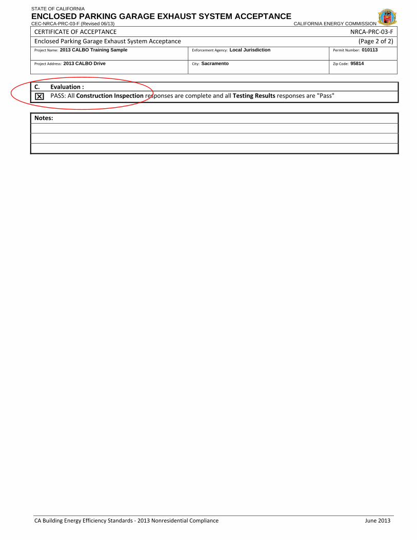
STATE OF CALIFORNIA
ENCLOSED PARKING GARAGE EXHAUST SYSTEM ACCEPTANCE CEC-NRCA-PRC-03-F (Revised 06/13) CALIFORNIA ENERGY COMMISSION
CERTIFICATE OF ACCEPTANCE NRCA‐PRC‐03‐F Enclosed Parking Garage Exhaust System Acceptance (Page 2 of 2)Project Name: 2013 CALBO Training Sample Enforcement Agency: Local Jurisdiction Permit Number: 010113
Project Address: 2013 CALBO Drive City: Sacramento Zip Code: 95814
CA Building Energy Efficiency Standards ‐ 2013 Nonresidential Compliance June 2013
C. Evaluation :
⌧ PASS: All Construction Inspection responses are complete and all Testing Results responses are "Pass"
Notes:

C A L I F O R N I A E N E R G Y C O M M I S S I O N29
§120.6 and the Field Inspector contInspector cont.
• NRCA forms req. for covered processes ( f i )(refrigerated warehouses)
NRCA-PRC-04 (evaporator fan motor controls)
NRCA-PRC-05 (evaporative condenser controls)
NRCA PRC 06 (air cooled condenser controls)NRCA-PRC-06 (air-cooled condenser controls)
NRCA-PRC-07 (variable speed compressor)
NRCA-PRC-08 (electric resistance underslab heating)
* Acceptance testing for covered processes will not req. a CMATT

C A L I F O R N I A E N E R G Y C O M M I S S I O N30
Insulation• New mandatory insulation reqs. in §120.7
• Maximum U-factor for roofs/ceilingsgIncl. metal buildings and wood framed
• Maximum U factor for walls• Maximum U-factor for wallsIncl. metal buildings and framed, light and heavy mass, wood framed and spandrel panels and glass curtain wallswood framed, and spandrel panels and glass curtain walls
• Maximum U-factor for floors and soffitsIncl. raised mass floors

2013 Building Energy Efficiency Standards Page 125
SECTION 120.7 –MANDATORY INSULATION REQUIREMENTS
SECTION 120.7 –MANDATORY INSULATION REQUIREMENTS Any newly constructed nonresidential and high-rise residential and hotel/motel building shall meet the minimum requirements in this Section.
(a) Roof/Ceiling Insulation. The opaque portions of the roof/ceiling that separates conditioned spaces from unconditioned spaces or ambient air shall meet the applicable requirements of Items 1 and 2 below:
1. Metal Building- The weighted average U-factor of the roof assembly shall not exceed 0.098.
2. Wood Framed and Others- The weighted average U-factor of the roof assembly shall not exceed 0.075.
(b) Wall Insulation. The opaque portions of walls that separate conditioned spaces from unconditioned spaces or ambient air shall meet the applicable requirements of Items 1 through 6 below:
1. Metal Building- The weighted average U-factor of the wall assembly shall not exceed 0.113.
2. Metal Framed- The weighted average U-factor of the wall assembly shall not exceed 0.105.
3. Light Mass Walls- A 6 inches or greater Hollow Core Concrete Masonry Unit shall have a U-factor not to exceed 0.440.
4. Heavy Mass Walls- A 8 inches or greater Hollow Core Concrete Masonry Unit shall have a U-factor not to exceed 0.690.
5. Wood Framed and Others- The weighted average U-factor of the wall assembly shall not exceed 0.110.
6 Spandrel Panels and Glass Curtain Wall- The weighted average U-factor of the Glass spandrel panels and glass curtain wall assembly shall not exceed 0.280.
(c) Floor and Soffit Insulation. The opaque portions of floors and soffits that separate conditioned spaces from unconditioned spaces or ambient air shall meet the applicable requirements of Items 1 and 2 below:
1. Raised Mass Floors- Shall have a minimum of 3 inches of lightweight concrete over a metal deck or the weighted average U-factor of the floor assembly shall not exceed 0.269.
2. Other Floors-The weighted average U-factor of the floor assembly shall not exceed 0.071.
3. Heated Slab Floor-A heated slab floor shall be insulated to meet the requirements of Section 110.8(g)

C A L I F O R N I A E N E R G Y C O M M I S S I O N31
§120.7 and the Plans ExaminerExaminer
• Still verify U-factor on NRCC ENV 01 (S ti B)NRCC-ENV-01 (Section B)
Envelope Details
M t t b b lMust meet or be below mandatory maximum values
• Still verify R-values on• Still verify R-values on building plans
Structural/ArchitecturalStructural/Architectural Plans
* Can req. a note block on structural/architectural plans

STATE OF CALIFORNIA
ENVELOPE COMPONENT APPROACH CEC-NRCC-ENV-01-E (Revised 06/13) CALIFORNIA ENERGY COMMISSION
CERTIFICATE OF COMPLIANCE NRCC‐ENV‐01‐E Envelope Component Approach (Page 1 of 3) Project Name: 2013 CALBO Training Sample Date Prepared: 01/01/14
CA Building Energy Efficiency Standards ‐ 2013 Nonresidential Compliance June 2013
A. GENERAL INFORMATION 1 Project Location: 2013 CALBO Drive 6 Compliance Method: ⌧ Component Unconditioned (file
Affidavit) 2 CA City and Zip Code: Sacramento, 95814 7 Building Front Orientation (deg or cardinal): North 3 Climate Zone: 12 8 Permitted Scope of Work ⌧New Construction Addition Alteration 4 Total Conditioned Floor
Area: 2,000 ft2 9 Building Type(s) ⌧ Nonresidential High‐Rise Residential Hotel/Motel Guest Room
5 Schools (Public School) Relocatable Public School Bldg. Conditioned Spaces Unconditioned Spaces Skylight Area for Large Enclosed Space ≥ 5000 ft2 (If checked include the NRCC‐ENV‐04‐E with submittal)
B. ENVELOPE DETAILS – Framed
1 2 3 4 5 6 7 8 9 10 11
Tag/ID Assembly Type Frame Material
Frame Depth
Frame Spacing
Appendix JA4 Reference
Cavity R‐value
Continuous Insulation R‐value Proposed
U‐Factor Required U‐Factor From
Tables, B, C, D Comments 1 Celing Wood 2 X 4 16 in. 4.2.1 R-38 R-0 0.026 0.039 2 Walls Wood 2 X 6 16 in. 4.3.1 R-19 R-4 0.074 0.059 3
C. ENVELOPE DETAILS – Non‐framed 1 2 3 4 5 6 7 8 9 10
Tag/ID Assembly Type Assembly Materials Thickness (inches)
Interior or Core
Insulation R‐value
Continuous Insulation R‐value
Appendix JA4 Reference
Proposed U‐Factor
Required U‐Factor from Tables, B, C, D Comments
D. ENVEL0PE DETAILS – Mass
1 2 3 4 5 6 7 8 9 10 11
Tag/ID Mass Type
Density (lb/ft3)
Mass Thickness (inches)
Furring Strip Thickness (inches)
Interior Insulation R‐value
Exterior Insulation R‐value
Appendix JA4 Reference
Proposed Insulation U‐factor
Required U‐Factor from Tables, B, C, D Comments

C A L I F O R N I A E N E R G Y C O M M I S S I O N32
§120.7 and the Field InspectorInspector
• Verify installed R-values:Still verify wall and raised floorStill verify wall and raised floor insulation at Insulation Stage
Still verify ceiling insulation at Final
Values must meet or exceed NRCC-ENV-01 formNRCC ENV 01 form
• Verify R-values on NRCI-ENV-01 formNRCI ENV 01 form
Must be registered starting 1/1/15

STATE OF CALIFORNIA
ENVELOPE CEC-NRCI-ENV-01-E (Revised 06/13) CALIFORNIA ENERGY COMMISSION
CERTIFICATE OF INSTALLATION NRCI‐ENV‐01‐E Envelope (Page 1 of 2)Project Name: 2013 CALBO Training Sample Enforcement Agency: Local Jurisdiction Permit Number: 010113
Project Address: 2013 CALBO Training Sample City: Sacramento Zip Code: 95814
CA Building Energy Efficiency Standards ‐ 2013 Nonresidential Compliance June 2013
GENERAL INFORMATION DATE OF BUILDING PERMIT
PERMIT #
BUILDING TYPE ⌧ Nonresidential
High‐Rise Residential Hotel/Motel Guest Room
PHASE OF CONSTRUCTION ⌧
New Construction Addition Alteration Unconditioned
If more than one person has responsibility for building construction, each person shall prepare and sign an Installation Certificate document applicable to the portion of construction for which they are responsible; alternatively, the person with chief responsibility for construction shall prepare and sign the Installation Certificate document(s) for the entire construction.
SCOPE OF RESPONSIBILITY
Enter the date of approval by enforcement agency of the Certificate of Compliance that provides the specifications for the energy efficiency measures for the scope of responsibility for this Installation Certificate.
Date:1/1/14
In the table below identify all applicable construction documents that specify the requirements for the scope of responsibility for this Installation Certificate.
Document Title or Description Applicable Sheets or Pages, Tables, Schedules, etc. Date Approved By the Enforcement
Agency Structural/Architecture Plans – Wall and Roof Insulation
S-1.2 – Assembly Specs R-19 Wall (batt; cavity); R-38 roof (rigid; roof deck)

C A L I F O R N I A E N E R G Y C O M M I S S I O N33
Building Commissioning• New mandatory commissioning reqs. in §120.8
• Applicable to all nonresidential buildingsBuildings < 10,000 ft2 only have to meet subsections (d) and (e)
• Requirements for:Owner’s Project Requirements (OPR)Basis of Design (BOD)Design Phase Design ReviewDesign Phase Design ReviewCommissioning Documents on PlansCommissioning PlanFunctional TestingFunctional TestingDocumentation and TrainingCommissioning Report

2013 Building Energy Efficiency Standards Page 126
SECTION 120.8 BUILDING COMMISSIONING
SECTION 120.8 BUILDING COMMISSIONING For all new nonresidential buildings, the Subsections of 120.8 (a) through (i) for building commissioning shall be included in the design and construction processes of the building project to verify that the building energy systems and components meet the owner’s or owner representative’s project requirements. All building systems and components covered by Sections 110.0, 120.0, 130.0, and 140.0 shall be included in the scope of the commissioning requirements in this Section, excluding covered processes. For buildings less than 10,000 ft2, only the design review requirements in Sections 120.8(d) and 120.8(e) shall be completed.
(a) Summary of Commissioning Requirements. The following items shall be completed:
1. Owner’s or owner representative’s project requirements;
2. Basis of design;
3. Design phase design review;
4. Commissioning measures shown in the construction documents;
5. Commissioning plan;
6. Functional performance testing;
7. Documentation and training; and
8. Commissioning report.
(b) Owner’s or Owner Representative’s Project Requirements (OPR). The energy-related expectations and requirements of the building shall be documented before the design phase of the project begins. This documentation shall include the following:
1. Energy efficiency goals;
3. Ventilation requirements;
4. Project program, including facility functions and hours of operation, and need for after hours operation; and
5. Equipment and systems expectations.
EXCEPTION to Section 120.8(b): Buildings less than 10,000 ft2.
(c) Basis of Design (BOD). A written explanation of how the design of the building systems meets the OPR shall be completed at the design phase of the building project, and updated as necessary during the design and construction phases. The Basis of Design document shall cover the following systems:
1. Heating, ventilation, air conditioning (HVAC) systems and controls;
2. Indoor lighting system and controls; and
3. Water heating systems and controls; and
4. Covered processes.
EXCEPTION to Section 120.8(c): Buildings less than 10,000 ft2.
(d) Design Phase Design Review.
1. Design Reviewer Requirements. For buildings less than 10,000 ft2, design phase design review may be completed by the design engineer. Buildings between 10,000 and 50,000 ft2 require completion of the Design Review Checklist by either an engineer in-house to the design firm but not associated with the building project, or a third party design engineer. For buildings larger than 50,000 ft2 or for buildings with complex mechanical systems, an independent, review of these documents by a third party design engineer is required.

2013 Building Energy Efficiency Standards Page 127
SECTION 120.8 BUILDING COMMISSIONING
2. Design Review. During the schematic design phase of the building project, the owner or owner’s representative, design team and design reviewer must meet to discuss the project scope, schedule and how the design reviewer will coordinate with the project team. The building owner or owner's representative shall include the Design Review Checklist compliance form in the Certificate of Compliance documentation (see Section 10-103).
3. Construction Documents Design Review. The Construction Documents Design Review compliance form lists the items that shall be checked by the design reviewer during the construction document review. The completed form shall be returned to the owner and design team for review and sign-off. The building owner or owner's representative shall include this Construction Documents Design Review compliance form in the Certificate of Compliance documentation (see Section 10-103).
(e) Commissioning measures shown in the construction documents. Include commissioning measures or requirements in the construction documents (plans and specifications). Commissioning measures or requirements should be clear, detailed and complete to clarify the commissioning process. These requirements should include the list of systems and assemblies commissioned, testing scope, roles and responsibilities of contractors, requirements for meetings, management of issues, the commissioning schedule, operations and maintenance manual development and of training, and checklist and test form development, execution and documentation. Include, for information only, roles of non-contractor parties.
(f) Commissioning Plan. Prior to permit issuance a commissioning plan shall be completed to document how the project will be commissioned and shall be started during the design phase of the building project. The Commissioning Plan shall include the following:
1. General project information; and
2. Commissioning goals; and
3 Systems to be commissioned; and
4. Plans to test systems and components, which shall include:
A. An explanation of the original design intent; and
B. Equipment and systems to be tested, including the extent of tests; and
C. Functions to be tested; and
D. Conditions under which the test shall be performed; and
E. Measurable criteria for acceptable performance; and
F. Commissioning team information; and
G. Commissioning process activities, schedules and responsibilities. Plans for the completion of commissioning requirements listed in Sections 120.8(g) through 120.8(i) shall be included.
EXCEPTION to Section 120.8(f): Buildings less than 10,000 ft2.
(g) Functional performance testing. Functional performance tests shall demonstrate the correct installation and operation of each component, system and system-to-system interface in accordance with the acceptance test requirements in Sections 120.5, 120.6, 130.4 and 140.9. Functional performance testing reports shall contain information addressing each of the building components tested, the testing methods utilized, and include any readings and adjustments made.
EXCEPTION to Section 120.8(g): Buildings less than 10,000 ft2.
(h) Documentation and training. A Systems Manual and Systems Operations Training shall be completed.
1. Systems manual. Documentation of the operational aspects of the building shall be completed within the Systems Manual and delivered to the building owner or representative and facilities operator. The Systems Manual shall include the following:
A. Site information, including facility description, history and current requirements; and
B. Site contact information; and
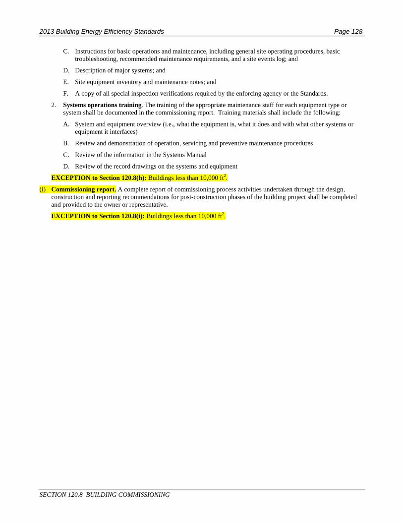
2013 Building Energy Efficiency Standards Page 128
SECTION 120.8 BUILDING COMMISSIONING
C. Instructions for basic operations and maintenance, including general site operating procedures, basic troubleshooting, recommended maintenance requirements, and a site events log; and
D. Description of major systems; and
E. Site equipment inventory and maintenance notes; and
F. A copy of all special inspection verifications required by the enforcing agency or the Standards.
2. Systems operations training. The training of the appropriate maintenance staff for each equipment type or system shall be documented in the commissioning report. Training materials shall include the following:
A. System and equipment overview (i.e., what the equipment is, what it does and with what other systems or equipment it interfaces)
B. Review and demonstration of operation, servicing and preventive maintenance procedures
C. Review of the information in the Systems Manual
D. Review of the record drawings on the systems and equipment
EXCEPTION to Section 120.8(h): Buildings less than 10,000 ft2.
(i) Commissioning report. A complete report of commissioning process activities undertaken through the design, construction and reporting recommendations for post-construction phases of the building project shall be completed and provided to the owner or representative.
EXCEPTION to Section 120.8(i): Buildings less than 10,000 ft2.

C A L I F O R N I A E N E R G Y C O M M I S S I O N34
Building Commissioning cont.• Design reviewer is responsible for verifying that
forms, plans, etc. comply with §120.8
Review may be completed by:
Design engineer for buildings < 10,000 ft2g g g
An in-house engineer not associated with the project, or a third party design engineer for buildings between 10,000 ft2 and 50,000 ft2
A third party design engineer for buildings > 50,000 ft2, or buildings with complex mechanical systems

C A L I F O R N I A E N E R G Y C O M M I S S I O N35
§120.8 and the Plans ExaminerExaminer
• Verify applicable Certificate f C li lof Compliance on plans
NRCC-CXR-01
NRCC-CXR-02
NRCC-CXR-03 (simple HVAC)
NRCC CXR 04 ( l HVAC)NRCC-CXR-04 (complex HVAC)
NRCC-CXR-05
• Verify qualifications of design reviewer
* Form must be registered starting 1/1/15

STATE OF CALIFORNIA
DESIGN REVIEW KICKOFF CEC-NRCC-CXR-01-E (Revised 06/13) CALIFORNIA ENERGY COMMISSION
CERTIFICATE OF COMPLIANCE – DATA FIELD DEFINITIONS AND CALCULATIONS NRCC‐CXR‐01‐E Design Review Kickoff (Page 1 of 1)Project Name: 2013 CALBO Training Sample Date Prepared: 01/01/14
CA Building Energy Efficiency Standards ‐ 2013 Nonresidential Compliance June 2013
A. General Information
Climate Zone: 12 Building Type: New Construction Conditioned Area (sf): 5,000 ft2 Reviewer's Name: Ms. Design Engineer Reviewer's Agency: Best Energy Comp. Enforcement Agency: Local Jurisdiction Permit Number: 010113
Enforcement Agency Use: Checked by Enforcement Agency Use: Date
DATE OF DESIGN REVIEW KICKOFF 01 / 01 / 14 DESIGN REVIEW CHECKLISTS PROVIDED TO DESIGN TEAM YES ⌧ NO □
DESIGN REVIEWER QUALIFICATIONS:
⌧ <10,000 ft2: design engineer
� >10,000 ft2 and <50,000ft2: in‐house engineer not associated with project or third‐party design engineer
� >50,000 ft2 or complex mechanical system: third‐party design engineer
LIST OF MEETING ATTENDEES:
⌧ Owner: Joe Owner_______________ ⌧ Design Reviewer: Ms. Design Engineer___________ ⌧ Project Manager: Jill Manager_________ ⌧ Design Engineer(s): Ms. Design Engineer_________ DOCUMENTS RECEIVED BY DESIGN REVIEWER FOR DESIGN REVIEW KICKOFF:
⌧ Owner's Project Requirements ⌧ Basis of Design or Narrative
⌧ Drawing Set (issue & date): 01/01/14_______________ ⌧ Specifications: Mech. Plans, Structural, Electrical ___ □ Other: ____________________________________ DESIGN REVIEW MEETING TOPICS:
PROJECT SCOPE: Shopping mall
DESIGN ELEMENTS AND ASSUMPTIONS: 10% above Title 24 Code
HVAC SYSTEM SELECTION: Simple HVAC – roof packaged units
RECOMMENDED ENERGY EFFICIENCY MEASURES: Cool roof on flat roof
OTHER COMMENTS:
COORDINATION:
TARGET CONSTRUCTION DOCUMENT REVIEW DATE: 01/01/14 TARGET PERMIT SUBMITTAL DATE: 05/01/14

STATE OF CALIFORNIA
COMMISSIONING – CONSTRUCTION DOCUMENTS CEC-NRCC-CXR-02-E (Revised 06/13) CALIFORNIA ENERGY COMMISSION
CERTIFICATE OF COMPLIANCE NRCC‐CXR‐02‐E Commissioning ‐ Construction Documents (Page 1 of 7)Project Name: Date Prepared:
CA Building Energy Efficiency Standards ‐ 2013 Nonresidential Compliance June 2013
General Information
Climate Zone: Building Type: Conditioned Area (sf): Reviewer's Name: Reviewer's Agency:
Note: Design Review for each system/subsystem must be submitted
Enforcement Agency: Permit Number:
Enforcement Agency Use: Checked by Enforcement Agency Use: Date
Code Section
Measure
Design Reviewer Designer Response
Yes. Com
plies
Doe
s Not Com
ply
Consider Better
Practice
Complies
Will In
clud
e in Next
Draft
Not In
clud
ed ‐
State Re
ason
ENVELOPE
JOINTS AND OTHER OPENINGS
110.7 Plans indicate that joints, penetrations and other openings in the building envelope shall be sealed to limit infiltration and exfiltration.
N/A
120.7 Roof/ceiling, wall and floor and soffit insulation must meet requirements identified in this section.
N/A
INSULATION AND ROOFING PRODUCTS
140.3(a)1.A
Roofing products for low‐sloped roofs meet minimum solar reflectance of 0.63 and minimum thermal emittance of 0.75 OR minimum Solar Reflectance Index of 75. Steep‐sloped roofs meet requirements of 0.20 and 0.75 OR 16, respectively.
N/A
140.3(a)1.A‐B
Exterior roofs, ceilings, and exterior walls, floors and soffits must have an overall assembly U‐factor no greater than the applicable value in TABLE 140.3‐B, C or D.
N/A
NOTES
LIGHTING
LIGHTING CONTROLS
130.1(a) Accessible, independent switching or a control device is included for all areas enclosed by ceiling height partitions.
N/A
130.1(a)4 General lighting is controlled separately from all other lighting systems.
N/A

STATE OF CALIFORNIA
COMMISSIONING – CONSTRUCTION DOCUMENTS CEC-NRCC-CXR-02-E (Revised 06/13) CALIFORNIA ENERGY COMMISSION
CERTIFICATE OF COMPLIANCE NRCC‐CXR‐02‐E Commissioning ‐ Construction Documents (Page 2 of 7)Project Name: Date Prepared:
CA Building Energy Efficiency Standards ‐ 2013 Nonresidential Compliance June 2013
130.1(b)
General lighting of enclosed spaces 100 sf or larger with a lighting load that exceeds 0.5 W/sf, have multi level lighting controls from at least one of the following methods: manual dimming, lumen maintenance, tuning, automatic daylighting controls, demand responsive lighting controls. Control steps are in accordance with Table 130.1‐A.
N/A
130.1(c) Shut off controls are controlled with occupant sensing controls, automatic time‐switch control, signal from another building system or other control and are shown for all indoor lighting systems.
N/A
130.1(c)5
Offices 250 square feet or smaller; multipurpose rooms of less than 1000 square feet, and classrooms and conference rooms of any size, shall be equipped with occupant sensor(s) to shut off the lighting.
N/A
130.1(c)6 Lighting in corridors and stairwells shall be controlled by occupant sensing controls that separately reduce lighting power in each space by at least 50% when the area is unoccupied.
N/A
130.1(e) For buildings greater than 10,000 sf, demand response controls should be included to reduce total building lighting power by a minimum of 15%.
N/A
DAYLIGHT AREA
140.3(c)
Daylight areas required for conditioned or unconditioned spaces greater than 5,000 ft2 of roof area and with ceiling height greater than 15 feet are shown on building plans and meet requirements of this section.
N/A
DAYLIGHT CONTROLS
130.1(d)2
All skylit daylit zones, primary sidelit daylit zones and secondary sidelit daylit zone are shown on plans. Controls of skylit and sidelit zones are independent and provide multi‐level lighting in accordance with Table 130.1‐A. Plans should indicate that general lighting power is reduced by a minimum of 65% when daylit illuminance is 150% of design illuminance.
N/A
Best Practice The locations of all photo sensors are shown on the plans. Height and position criteria are also shown. Photo sensors are not installed in direct sunlight nor in direct light of lighting fixtures.
Best Practice
Specification defines the amount of light to be gathered by the photo sensor in relation to its location for the lighted surface and this matches the application. For example: if 5 FC on the horizontal floor is the maintained lighting level and the sensor is mounted 15 feet off the ground, the sensor must be capable of detecting 5 FC from floor at that distance.
Best Practice
Daylight dimming zones have consistent window/glazing types and orientation (e.g., a single zone should not include east and south facing glass or have a section of tall window‐wall and another wall section of smaller windows).
Best Practice Specifications state that sensor and dimming settings are set up and calibrated after furniture and final finishes and all lighting equipment are installed and operational.

STATE OF CALIFORNIA
COMMISSIONING – CONSTRUCTION DOCUMENTS CEC-NRCC-CXR-02-E (Revised 06/13) CALIFORNIA ENERGY COMMISSION
CERTIFICATE OF COMPLIANCE NRCC‐CXR‐02‐E Commissioning ‐ Construction Documents (Page 3 of 7)Project Name: Date Prepared:
CA Building Energy Efficiency Standards ‐ 2013 Nonresidential Compliance June 2013
Best Practice
A complete step by step sequence of operation is included defining the lighting levels (max and min), zones, interaction with occupants, interaction with occupancy and time‐clock controls, and interaction with lighting on‐off or dimming switches.
Best Practice Interface with BAS or other lighting control systems is defined and is fully compatible for all features of the sequence required. Interface shown on lighting and controls drawings.
Best Practice Daylight dimming controls are properly integrated with emergency fixtures, using separate ballasts for dimming and emergency backup.
Best Practice
Daylight zones that penetrate more than one row of fixtures from the windows have the fixtures closer to the windows receiving a lower light command to create a more even lighting and save energy.
Best Practice The ballast specified is able to turn down as low as the specified daylight dimming system.
Best Practice
To save energy, dimming specifications require that the illumination during night time shall be adjusted to be 20% or more lower than the daytime target, since the apparent illumination at night will appear higher.
OUTDOOR LIGHTING CONTROLS AND EQUIPMENT
130.2(a) Outdoor incandescent lighting rated over 100 watts is controlled by a motion sensor.
N/A
130.2(c)1 All outdoor lighting is controlled by photocontrol or outdoor astronomical time‐switch control.
N/A
130.2(c)3
Outdoor lighting where bottom of luminaire is mounted 24 feet or less above the ground is controlled by motion sensors or other controls that are capable of reducing the lighting power of each luminaire by 40 to 80% in response to the area being vacated.
N/A
130.2(c)4 Automatic lighting controls shown on plans for building façade, ornamental hardscape or outdoor dining lighting includes part‐night lighting control, motion sensor control, or time‐based control.
N/A
NOTES
SERVICE HOT WATER HEATING
110.3(c)2 SHW systems with circulating pumps or with electrical heat trace have automatic controls that turn off the system during unoccupied periods.
N/A
120.3 Pipe insulation for space conditioning and service water‐heating with fluid temperatures listed in Table 120.3‐A have insulation levels as specified in subsection (a) and (b).
N/A

STATE OF CALIFORNIA
COMMISSIONING – CONSTRUCTION DOCUMENTS CEC-NRCC-CXR-02-E (Revised 06/13) CALIFORNIA ENERGY COMMISSION
CERTIFICATE OF COMPLIANCE NRCC‐CXR‐02‐E Commissioning ‐ Construction Documents (Page 4 of 7)Project Name: Date Prepared:
CA Building Energy Efficiency Standards ‐ 2013 Nonresidential Compliance June 2013
NOTES
HVAC DESIGN ‐ ALL BUILDINGS HVAC EQUIPMENT
110.2(a) Equipment meets efficiency requirements of Tables 110.2‐A through 110.2‐K.
120.2(i) All air‐cooled, unitary, DX units (packaged, split‐system, heat pumps and VRF) with economizers are equipped with Fault Detection and Diagnostics systems.
120.3 Pipe insulation for space conditioning and service water‐heating with fluid temperatures listed in Table 120.3‐A have insulation levels as specified in subsection (a) and (b).
140.4(a)
Mechanical heating and cooling equipment are the smallest size, within the available options of the desired equipment line, necessary to meet the design heating and cooling loads of the building, as calculated according to the requirements of Section 140.4(b).
140.4(c)4 HVAC motors for fans that are less than 1 hp and 1/12 hp or greater are ECM or have a minimum motor efficiency of 70%. Motors also have means to adjust motor speed for balancing or remote control.
140.4(g) Electric resistance heating systems are not provided for space heating for cases were exceptions are not allowed.
Best Practice In drier climates and when large outdoor air fractions are required, evaporative pre‐cooling packages were evaluated to pre‐cool outside air and cool the air flowing over the DX condensing unit.
Best Practice In semi‐arid climates, two‐stage evaporative cooling has been evaluated in lieu of mechanical refrigeration.
HVAC ZONING
Best Practice Zone each air handler to serve only areas with common loads to allow more aggressive control strategies and improve comfort. Have different AHU's serving core vs. perimeter areas.
Best Practice
The design accommodates partial occupancy energy savings when the owner’s requirements or narrative describe any possibility of partial occupancy, by zoning air handlers by floor or by part of a floor, or by incorporating controlled floor dampers, or VAV air terminals going totally shut when not occupied, etc.
CONTROLS

STATE OF CALIFORNIA
COMMISSIONING – CONSTRUCTION DOCUMENTS CEC-NRCC-CXR-02-E (Revised 06/13) CALIFORNIA ENERGY COMMISSION
CERTIFICATE OF COMPLIANCE NRCC‐CXR‐02‐E Commissioning ‐ Construction Documents (Page 5 of 7)Project Name: Date Prepared:
CA Building Energy Efficiency Standards ‐ 2013 Nonresidential Compliance June 2013
120.2(a) and (b)
Each zone is controlled by an individual thermostatic control. Controls are capable of setting temperatures to 55°F for heating and 85°F for cooling and provide a temperature deadband of at least 5°F if controlling both heating and cooling.
120.2(e)
Each space conditioning system is equipped with controls to shut the system off during periods of nonuse and will temporarily operate the system to maintain setback and setup temperatures while keeping ventilation dampers closed.
120.2(e)3
Systems serving multipurpose rooms less than 100 sf and classrooms, conference, auditorium or meeting center rooms greater than 750 sf have occupancy sensors that interface with HVAC controls to automatically setup the cooling setpoint by 2F or more and setback the heating setpoint by 2F or more and automatically reset the minimum required ventilation rate. These occupant sensor ventilation control devices must meet the requirements of section 120.1(c)5.
120.2(f) Outdoor air supply and exhaust equipment shall be installed with dampers that automatically close upon fan shutdown.
120.2(g) Each space‐conditioning system serving multiple zones with a combined conditioned floor area of more than 25,000 square feet shall be designed, installed, and controlled to serve isolation areas.
120.2(h) HVAC systems with DDC to the Zone level shall be programmed to allow centralized demand shed for non‐critical zones.
140.4(d) Zone controls prevent reheating, recooling and simultaneous provisions of heating and cooling to the same zone.
Best Practice
Each wall mounted thermostat is located away from potential sources that would adversely affect the reading (close to copiers, direct sunlight, below or above a supply air diffuser or convector, etc.).Any thermostats mounted on exterior walls are installed in sealed and insulated junction boxes.
Best Practice Corner office should always have their own thermostats, air terminal boxes or fin‐tube radiators.
Best Practice
Multiple air terminal boxes in a single large open space are served by a single thermostat, or multiple thermostat signals are polled and altered, to prevent fighting of terminals and simultaneous heating and cooling.
Best Practice Control sequences are listed for equipment operated by stand‐alone packaged controls. Unoccupied sequences should be included.
Best Practice
Control sequences exist for each piece of equipment listed in the equipment schedule that is monitored or controlled by the building automation system (BAS). Unoccupied sequences should be included.
Best Practice
Outside air temperature sensors should be in a commercially designed solar shield located on a north wall or some other location out of direct sunlight and away from building exhaust or heat rejection equipment.
VENTILATION RATES

STATE OF CALIFORNIA
COMMISSIONING – CONSTRUCTION DOCUMENTS CEC-NRCC-CXR-02-E (Revised 06/13) CALIFORNIA ENERGY COMMISSION
CERTIFICATE OF COMPLIANCE NRCC‐CXR‐02‐E Commissioning ‐ Construction Documents (Page 6 of 7)Project Name: Date Prepared:
CA Building Energy Efficiency Standards ‐ 2013 Nonresidential Compliance June 2013
120.1(a)2 The outdoor air‐ventilation rate and air‐distribution assumptions made in the design of the ventilating system are clearly identified on the plans.
120.1(b)
Each space is designed to have natural ventilation OR mechanical ventilation that is no less than the larger of conditioned floor area times the requirements in Table 120.1‐A or 15 cfm times the expected number of occupants.
Best Practice The minimum and maximum outdoor air rates for each air handler are listed on the equipment schedules.
Best Practice The outdoor air‐ventilation rates are based on planned owner occupancy as defined in owner's design intent and are not based on maximum egress occupancy rates.
Best Practice Heat recovery is specified on fan systems where the design outside air flow rate is greater than 70% and design supply air flow rate is greater than 5,000 cfm.
DEMAND CONTROL VENTILATION (DCV)
120.1(c)3‐4
HVAC systems that have an economizer, serve a space with a design occupant density greater than or equal to 25 people per 1000 sf, and are either a single zone system with any controls or multiple zone system with DDC controls to the zone level must have demand control ventilation controls. The following must be met: A. CO2 sensors installed in each room served by systems with DCV controls B. CO2 sensors are located between 3 ft and 6 ft above the floor C. CO2 concentrations maintained at less than or equal to 600 ppm plus outdoor ppm D. During hours of expected occupancy, controls maintain the system ventilation rate.
N/A
ALL HVAC SYSTEMS ‐ ECONOMIZERS
140.4(e)1 and 3
Each cooling fan system that has a design mechanical cooling capacity over 54,000 Btu/h has an air economizer or a water economizer. Air economizers must comply with the high limit shutoff controls shown in Table 140.4‐B.
140.4(e)2.B Plans indicate integrated economizer controls are set up such that partial cooling is provided by the economizer even when additional mechanical cooling is required.
Best Practice Economizer dampers are specified to be driven by direct drive actuators rather than rod linkages, which can be a major cause of economizer malfunction.
Best Practice Barometric relief is used, if possible. If not, relief fans(rather than return fans) are used in most cases.
Best Practice
Outdoor and return air sensors are properly selected, properly located to provide accurate and repeatable measurements for controlling economizer operation. Averaging sensors cover the entire duct or coil face areas.
DUCT DESIGN
120.4(a) All air distribution system ducts and plenums must be installed, sealed and insulated as required by 120.4(a).

STATE OF CALIFORNIA
COMMISSIONING – CONSTRUCTION DOCUMENTS CEC-NRCC-CXR-02-E (Revised 06/13) CALIFORNIA ENERGY COMMISSION
CERTIFICATE OF COMPLIANCE NRCC‐CXR‐02‐E Commissioning ‐ Construction Documents (Page 7 of 7)Project Name: Date Prepared:
CA Building Energy Efficiency Standards ‐ 2013 Nonresidential Compliance June 2013
140.4(l) Plans indicate duct sealing leakage rates.
Best Practice
Ducts utilize low static pressure design. Identify the most restrictive branch from the fan to the last air terminal unit. Identify possible means of significantly reducing the pressure drop. Branch duct systems are designed for equal pressure drop, when possible.
Best Practice Duct branches with significantly differing static pressure requirements have volume control strategically placed to aid in TAB work.
Best Practice Fans discharge into duct sections that remain straight for as long as possible (ideally 10 duct diameters) to reduce fan inefficiencies from system effects.
Best Practice Duct velocities are generally below 2,000 fpm for ducts in ceiling plenums, 1500 fpm for exposed ducts and 3500 fpm in mechanical rooms and non‐noise sensitive shafts.
Best Practice
Duct friction rates are generally less than 0.25” WC per 100 lineal feet nearer the fan, 0.15 to 0.20” in the main ducts and 0.08 to 0.12” WC /100’ nearer the end of the system. Designs over these rates should be questioned. Very energy efficient design can lower these values by up to 40%.
Best Practice
Ensure that drawings are sufficiently detailed to ensure that distribution system design intent is adequately conveyed. If sufficient detail is not included in drawings, installations may result in significantly higher pressure drops and hence higher energy consumption and other operating issues.
ACCEPTANCE AND COMMISSIONING
120.5(a) Acceptance requirements clearly identified in construction documents.
N/A
120.8(e) Commissioning measures or requirements are reflected in the construction documents.
N/A
120.8(g) Requirements for functional performance tests are reflected in the construction documents.
N/A
NOTES

STATE OF CALIFORNIA
CONSTRUCTION DOCUMENTS CEC-NRCC-CXR-03-E (Revised 06/13) CALIFORNIA ENERGY COMMISSION
CERTIFICATE OF COMPLIANCE NRCC‐CXR‐03‐E Construction Documents (Page 1 of 1)Project Name: 2013 CALBO Training Sample Date Prepared: 01/01/14
CA Building Energy Efficiency Standards ‐ 2013 Nonresidential Compliance June 2013
General Information
Climate Zone: 12 Building Type: New Construction Conditioned Area (sf): 2,500 ft2 Reviewer's Name: Ms. Design Reviewer Reviewer's Agency: Best Energy Comp.
Note: Design Review for each system/subsystem must be submitted
Enforcement Agency: Local Jurisdiction Permit Number: 010113
Enforcement Agency Use: Checked by Enforcement Agency Use: Date
Code Section
Measure
Design Reviewer Designer Response
Yes. Com
plies
Doe
s Not
Comply
Consider Better
Practice
Complies
Will In
clud
e in
Next Draft
Not In
clud
ed ‐
State Re
ason
SIMPLE HVAC SYSTEMS
DESIGN ‐ FAN SYSTEMS
120.1(e) Measured outdoor air rates of constant volume mechanical ventilation and space‐conditioning systems shall be within 10% of required outside air rate.
⌧
⌧
140.4(c)1 Fan power index at design conditions meets the following: 0.8 watts per cfm supply air for constant volume fan systems with total horsepower over 25 hp
⌧
⌧
Best Practices
Fans appear to be correctly sized for application, accounting for a factor of safety, diversity and redundancy issues.
⌧
⌧
CONTROLS
110.2(c) Controls for unitary single zone, air conditioners, heat pumps and furnaces must have a setback thermostat.
⌧
⌧
140.4(m)
Cooling systems identified in Table 140.4‐D have fan controls to vary the indoor fan airflow as a function of load: 1. DX and chilled water cooling systems that control capacity based on occupied space temperature have a minimum of 2 stages of control with no more than 66% speed operating at stage 1 and draw no more than 40% of fan power at full fan speed when operating at 66% speed.2. Systems that control space temperature by modulating airflow to the space have proportional fan control such that at 50% air flow the power draw is no more than 30% of fan power at full fan speed. 3. Systems with air side economizer have a minimum of 2 speeds of fan control during economizer operation.
⌧
⌧
NOTES

C A L I F O R N I A E N E R G Y C O M M I S S I O N36
Lighting – Multi-Level2008 – §131(b)
• Multi-level lighting controls
2013 – §130.1(b)• Multi-level lighting controlsMulti level lighting controls
req. for:
Enclosed spaces ≥ 100 ft2; and
Multi level lighting controls req. for
Enclosed space ≥ 100 ft2; and
Have a lighting load > 0.8 W/ft2
Have a lighting load > 0.5 W/ft2
• One control step between 30% and 70%
• Control steps and uniform illuminance dependent on luminaire type
• Uniform illuminance with dimmers, A/B switching, etc.
ypIn accordance with TABLE 130.1-A

2013 Building Energy Efficiency Standards Page 138
SECTION 130.1 – INDOOR LIGHTING CONTROLS THAT SHALL BE INSTALLED
TABLE 130.1-A MULTI-LEVEL LIGHTING CONTROLS AND UNIFORMITY REQUIREMENTS
Luminaire Type Minimum Required Control Steps
( percent of full rated power1 ) Uniform level of illuminance shall
be achieved by:
Line-voltage sockets except GU-24
Continuous dimming 10-100 percent Low-voltage incandescent systems
LED luminaires and LED source systems
GU-24 rated for LED
GU-24 sockets rated for fluorescent > 20 watts Continuous dimming 20-100 percent Pin-based compact fluorescent > 20 watts2
GU-24 sockets rated for fluorescent ≤ 20 watts Minimum one step between
30-70 percent
Stepped dimming; or
Continuous dimming; or
Switching alternate lamps in a luminaire
Pin-based compact fluorescent ≤ 20 watts2
Linear fluorescent and U-bent fluorescent ≤ 13 watts
Linear fluorescent and U-bent fluorescent > 13 watts
Minimum one step in each range: Stepped dimming; or
Continuous dimming; or
switching alternate lamps in each luminaire, having a minimum of 4 lamps per luminaire, illuminating the same area and in the same manner
20-40 % 50-70 % 80-85 % 100 %
Track Lighting Minimum one step between
30 – 70 percent
Step dimming; or
Continuous dimming; or
Separately switching circuits in multi-circuit track with a minimum of two circuits.
HID > 20 watts
Minimum one step between 50 - 70 percent
Stepped dimming; or
Continuous dimming; or
Switching alternate lamps in each luminaire, having a minimum of 2 lamps per luminaire, illuminating the same area and in the same manner.
Induction > 25 watts
Other light sources
1. Full rated input power of ballast and lamp, corresponding to maximum ballast factor
2. Includes only pin based lamps: twin tube, multiple twin tube, and spiral lamps

C A L I F O R N I A E N E R G Y C O M M I S S I O N37
Lighting – Shut-OFF2008 – §131(d)
• Shut-off controls req for
2013 – §130.1(c)• Countdown time switches Shut off controls req. for
every floor
• Can be achieved with:
prohibited (some exceptions)
• Occupant sensors that shut off
Occupancy sensors
Automatic time-switch
all lighting req. in specific areas
• Occupant sensors with partialAutomatic time switch
Countdown timer switch
Etc.
• Occupant sensors with partial ON/OFF controls req. in specific areas
Etc.• Captive key cards req. in
hotel/motel guest rooms

2013 Building Energy Efficiency Standards Page 134
SECTION 130.1 – INDOOR LIGHTING CONTROLS THAT SHALL BE INSTALLED
B. Lumen maintenance as defined in Section 100.1
C. Tuning as defined in Section 100.1
D. Automatic daylighting controls in accordance with Section 130.1(d)
E. Demand responsive lighting controls in accordance with Section 130.1(e)
EXCEPTION 1 to Section 130.1(b): Classrooms, with a connected general lighting load of 0.7 watts per square feet and less, shall have at least one control step between 30-70 percent of full rated power.
EXCEPTION 2 to Section 130.1(b): An area enclosed by ceiling height partitions that has only one luminaire with no more than two lamps.
(c) Shut-OFF Controls
1. In addition to lighting controls installed to comply with Sections 130.1(a) and (b), all installed indoor lighting shall be equipped with controls that meet the following requirements:
A. Shall be controlled with an occupant sensing control, automatic time-switch control, signal from another building system, or other control capable of automatically shutting OFF all of the lighting when the space is typically unoccupied; and
B. Separate controls for the lighting on each floor; and
C. Separate controls for a space enclosed by ceiling height partitions not exceeding 5,000 square feet; and
EXCEPTION to Section 130.1(c)1C: In the following function areas the area controlled may not exceed 20,000 square feet: Malls, auditoriums, single tenant retail, industrial, convention centers, and arenas,
D. Separate controls for general, display, ornamental, and display case lighting.
EXCEPTION 1 to Section 130.1(c)1: Where the lighting is serving an area that is in continuous use, 24 hours per day/365 days per year.
EXCEPTION 2 to Section 130.1(c)1: Lighting complying with Section 130.1(c)5, or 7.
EXCEPTION 3 to Section 130.1(c)1: In office buildings, up to 0.05 watts per square foot of lighting in any area within a building may be continuously illuminated, provided that the area is designated an emergency egress area on the plans and specifications submitted to the enforcement agency under Section 10-103(a)2 of Part 1.
EXCEPTION 4 to Section 130.1(c)1: Electrical equipment rooms subject to Article 110.26(D) of the California Electric Code.
2. Countdown timer switches shall not be used to comply with the automatic shut-OFF control requirements in Section 130.1(c)1.
EXCEPTION 1 to Section 130.1(c)2: Single-stall bathrooms less than 70 square feet, and closets less than 70 square feet may use countdown timer switches with a maximum setting capability of ten minutes to comply with the automatic shut-Off requirements.
EXCEPTION 2 to Section 130.1(c)2: Lighting in a Server Aisle in a Server Room, as defined in Section 100.1, may use countdown timer switches with a maximum setting capability of 30 minutes to comply with the automatic shut-OFF requirements.
3. If an automatic time-switch control, other than an occupant sensing control, is installed to comply with Section 130.1(c)1, it shall incorporate an override lighting control that:
A. Complies with Section 130.1(a); and
B. Allows the lighting to remain ON for no more than 2 hours when an override is initiated.
EXCEPTION to Section 130.1(c)3B: In the following function areas, the override time may exceed 2 hours: Malls, auditoriums, single tenant retail, industrial, and arenas where captive-key override is utilized.

2013 Building Energy Efficiency Standards Page 135
SECTION 130.1 – INDOOR LIGHTING CONTROLS THAT SHALL BE INSTALLED
4. If an automatic time-switch control, other than an occupant sensing control, is installed to comply with Section 130.1(c)1, it shall incorporate an automatic holiday "shut-OFF" feature that turns OFF all loads for at least 24 hours, and then resumes the normally scheduled operation.
EXCEPTION to Section 130.1(c)4: In retail stores and associated malls, restaurants, grocery stores, churches, and theaters, the automatic time-switch control is not required to incorporate an automatic holiday shut-OFF feature.
5. Areas where Occupant Sensing Controls are required to shut OFF All Lighting. In offices 250 square feet or smaller, multipurpose rooms of less than 1,000 square feet, classrooms of any size, and conference rooms of any size, lighting shall be controlled with occupant sensing controls to automatically shut OFF all of the lighting when the room is unoccupied. In addition, controls shall be provided that allow the lights to be manually shut-OFF in accordance with Section 130.1(a) regardless of the sensor status.
6. Areas where partial ON/OFF occupant sensing controls are required in addition to complying with Section 130.1(c)1.
A. In aisle ways and open areas in warehouses, lighting shall be controlled with occupant sensing controls that automatically reduce lighting power by at least 50 percent when the areas are unoccupied. The occupant sensing controls shall independently control lighting in each aisle way, and shall not control lighting beyond the aisle way being controlled by the sensor.
EXCEPTION 1 to Section 130.1(c)6A: In aisle ways and open areas in warehouses in which the installed lighting power is 80 percent or less of the value allowed under the Area Category Method, occupant sensing controls shall reduce lighting power by at least 40 percent.
EXCEPTION 2 to Section 130.1(c)6A: When metal halide lighting or high pressure sodium lighting is installed in warehouses, occupant sensing controls shall reduce lighting power by at least 40 percent.
B. In library book stack aisles 10 feet or longer that are accessible from only one end, and library book stack aisles 20 feet or longer that are accessible from both ends, lighting shall be controlled with occupant sensing controls that automatically reduce lighting power by at least 50 percent when the areas are unoccupied. The occupant sensing controls shall independently control lighting in each aisle way, and shall not control lighting beyond the aisle way being controlled by the sensor.
C. Lighting installed in corridors and stairwells shall be controlled by occupant sensing controls that separately reduce the lighting power in each space by at least 50 percent when the space is unoccupied. The occupant sensing controls shall be capable of automatically turning the lighting fully ON only in the separately controlled space, and shall be automatically activated from all designed paths of egress.
7. Areas where partial ON/OFF occupant sensing controls are required instead of complying with Section 130.1(c)1.
A. Lighting in stairwells and common area corridors that provide access to guestrooms and dwelling units of high-rise residential buildings and hotel/motels shall be controlled with occupant sensing controls that automatically reduce lighting power by at least 50 percent when the areas are unoccupied. The occupant sensing controls shall be capable of automatically turning the lighting fully ON only in the separately controlled space, and shall be automatically activated from all designed paths of egress.
EXCEPTION to Section 130.1(c)7A: In corridors and stairwells in which the installed lighting power is 80 percent or less of the value allowed under the Area Category Method, occupant sensing controls shall reduce power by at least 40 percent.
B. In parking garages, parking areas and loading and unloading areas, general lighting shall be controlled by occupant sensing controls having at least one control step between 20 percent and 50 percent of design lighting power. No more than 500 watts of rated lighting power shall be controlled together as a single zone. A reasonably uniform level of illuminance shall be achieved in accordance with the applicable requirements in TABLE 130.1-A. The occupant sensing controls shall be capable of automatically turning the lighting fully ON only in the separately controlled space, and shall be automatically activated from all designed paths of egress.

2013 Building Energy Efficiency Standards Page 136
SECTION 130.1 – INDOOR LIGHTING CONTROLS THAT SHALL BE INSTALLED
Interior areas of parking garages are classified as indoor lighting for compliance with Section 130.1(c)7B. Parking areas on the roof of a parking structure are classified as outdoor hardscape and shall comply with the applicable provisions in Section 130.2.
EXCEPTION to Section 130.1(c)7B: Metal halide luminaires with a lamp plus ballast mean system efficacy of greater than 75 lumens per watt, used for general lighting in parking garages, parking areas and loading and unloading areas, shall be controlled by occupant sensing controls having at least one control step between 20 percent and 60 percent of design lighting power.
8. Hotel motel guest rooms shall have captive card key controls, occupancy sensing controls, or automatic controls such that, no longer than 30 minutes after the guest room has been vacated, lighting power is switched off. EXCEPTION to Section 130.1(c)8: One high efficacy luminaire as defined in TABLE 150.0-A or 150.0-B that is switched separately and where the switch is located within 6 feet of the entry door.
(d) Automatic Daylighting Controls.
1. Daylit Zones shall be defined as follows:
A. SKYLIT DAYLIT ZONE is the rough area in plan view under each skylight, plus 0.7 times the average ceiling height in each direction from the edge of the rough opening of the skylight, minus any area on a plan beyond a permanent obstruction that is taller than the following: A permanent obstruction that is taller than one-half the distance from the floor to the bottom of the skylight. The bottom of the skylight is measured from the bottom of the skylight well for skylights having wells, or the bottom of the skylight if no skylight well exists.
For the purpose of determining the skylit daylit zone, the geometric shape of the skylit daylit zone shall be identical to the plan view geometric shape of the rough opening of the skylight; for example, for a rectangular skylight the skylit daylit zone plan area shall be rectangular, and for a circular skylight the skylit daylit zone plan area shall be circular.
B. PRIMARY SIDELIT DAYLIT ZONE is the area on a plan directly adjacent to each vertical glazing, one window head height deep into the area, and window width plus 0.5 times window head height wide on each side of the rough opening of the window, minus any area on a plan beyond a permanent obstruction that is 6 feet or taller as measured from the floor.
C. SECONDARY SIDELIT DAYLIT ZONE is the area on a plan directly adjacent to each vertical glazing, two window head heights deep into the area, and window width plus 0.5 times window head height wide on each side of the rough opening of the window, minus any area on a plan beyond a permanent obstruction that is 6 feet or taller as measured from the floor.
Note: Modular furniture walls shall not be considered a permanent obstruction.
2. Luminaires providing general lighting that are in or are partially in the Skylit Daylit Zones or the Primary Sidelit Daylit Zones shall be controlled independently by fully functional automatic daylighting controls that meet the applicable requirements of Section 110.9, and the applicable requirements below:
A. All Skylit Daylit Zones and Primary Sidelit Daylit Zones shall be shown on the plans.
B. Luminaires in the Skylit Daylit Zone shall be controlled separately from those in the Primary Sidelit Daylit Zones.
C. Luminaires that fall in both a Skylit and Primary Sidelit Daylit Zone shall be controlled as part of the Skylit Daylit Zone.
D. Automatic Daylighting Control Installation and Operation. For luminaires in daylight zones, automatic daylighting controls shall be installed and configured to operate according to all of the following requirements:
i. Photosensors shall be located so that they are not readily accessible to unauthorized personnel, and the location where calibration adjustments are made to automatic daylighting controls shall not be readily accessible to unauthorized personnel.

C A L I F O R N I A E N E R G Y C O M M I S S I O N
i i
38
Lighting –Acceptance/Installation Cert.Acceptance/Installation Cert. 2008 – §134 2013 – §130.4
• Testing mandatory if controls/systems installed for:
• Identified as “NRCA-LTI”Must be performed by Certified Lighting Controlsfor:
Multi-level controls
Shut off controls
Certified Lighting Controls Acceptance Test Technician (CLCATT)
Shut-off controls
Daylighting controls
Automatic daylighting controls
• New Certificate(s) of Installation req.
Identified as “NRCI LTI”Automatic daylighting controls
• Identified as “LTG-A”
Identified as NRCI-LTI
Completed by installing contractor

2013 Building Energy Efficiency Standards Page 143
SECTION 130.4 –LIGHTING CONTROL ACCEPTANCE AND INSTALLATION CERTIFICATE REQUIREMENTS
SECTION 130.4 –LIGHTING CONTROL ACCEPTANCE AND INSTALLATION CERTIFICATE REQUIREMENTS (a) Lighting Control Acceptance Requirements. Before an occupancy permit is granted for a newly constructed
building or area, or a new lighting system serving a building, area, or site is operated for normal use, indoor and outdoor lighting controls serving the building, area, or site shall be certified as meeting the Acceptance Requirements for Code Compliance in accordance with Section 130.4. A Certificate of Acceptance shall be submitted to the enforcement agency under Section 10-103(a) of Part 1, that:
1. Certifies plans, specifications, installation certificates, and operating and maintenance information meet the requirements of Part 6.
2. Completes the applicable procedures in Reference Nonresidential Appendix NA7.6, NA7.7, NA7.8, and NA7.9; and submits all applicable compliance forms.
3. Certifies that automatic daylight controls comply with Section 130.1(d) and Reference Nonresidential Appendix NA7.6.1
4. Certifies that lighting shut-OFF controls comply with Section 130.1(c) and Reference Nonresidential Appendix NA7.6.2
5. Certifies that demand responsive controls comply with Section 130.1(e) and Reference Nonresidential Appendix NA7.6.3
6. Certifies that outdoor lighting controls comply with the applicable requirements of Section 130.2(c) and Reference Nonresidential Appendix NA7.8.
(b) Lighting Control Installation Certificate Requirements. To be recognized for compliance with Part 6 an Installation Certificate shall be submitted in accordance with Section 10-103(a) for any lighting control system, Energy Management Control System, track lighting integral current limiter, track lighting supplementary overcurrent protection panel, interlocked lighting system, lighting Power Adjustment Factor, or additional wattage available for a videoconference studio, in accordance with the following requirements, as applicable:
1. Certification that when a lighting control system is installed to comply with lighting control requirements in Part 6 it complies with the applicable requirements of Section 110.9; and complies with Reference Nonresidential Appendix NA7.7.1.
2. Certification that when an Energy Management Control System is installed to function as a lighting control required by Part 6 it functionally meets all applicable requirements for each application for which it is installed, in accordance with Sections 110.9, 130.0 through 130.5, 140.6 through 150.0, and 150.2; and complies with Reference Nonresidential Appendix NA7.7.2.
3. Certification that line-voltage track lighting integral current limiters comply with the applicable requirements of Section 110.9 and installed wattage has been determined in accordance with Section 130.0(c); and comply with Reference Nonresidential Appendix NA7.7.3.
4. Certification that line-voltage track lighting supplementary overcurrent protection panels comply with the applicable requirements of Section 110.9 and installed wattage has been determined in accordance with Section 130.0(c); and comply with Reference Nonresidential Appendix NA7.7.4.
5. Certification that interlocked lighting systems used to serve an approved area comply with Section 140.6(a)1; and comply with Reference Nonresidential Appendix NA7.7.5.
6. Certification that lighting controls installed to earn a lighting Power Adjustment Factor (PAF) comply with Section 140.6(a)2; and comply with Reference Nonresidential Appendix NA7.7.6.
7. Certification that additional lighting wattage installed for a videoconference studio complies with Section 140.6(c)2Gvii; and complies with Reference Nonresidential Appendix NA7.7.7.

2013 Building Energy Efficiency Standards Page 144
SECTION 130.5 –ELECTRICAL POWER DISTRIBUTION SYSTEMS
(c) When certification is required by Title 24, Part 1, Section 10-103-A, the acceptance testing specified by Section 130.4 shall be performed by a Certified Lighting Controls Acceptance Test Technician (CLCATT). If the CLCATT is operating as an employee, the CLCATT shall be employed by a Certified Lighting Controls Acceptance Test Employer. The CLCATT shall disclose on the Certificate of Acceptance a valid CLCATT certification identification number issued by an approved Acceptance Test Technician Certification Provider. The CLCATT shall complete all Certificate of Acceptance documentation in accordance with the applicable requirements in Section 10-103(a)4.
NOTE: Authority cited: Sections 25402, 25402.1, 25213, Public Resources Code. Reference: Sections 25007, 25402(a)-(b), 25402.1, 25402.4, 25402.5, 25402.8 and 25910, Public Resources Code.
SECTION 130.5 –ELECTRICAL POWER DISTRIBUTION SYSTEMS (a) Service Metering. Each electrical service shall have permanently installed user-accessible metering of total electrical
energy use per TABLE 130.5-A.
(b) Disaggregation of Electrical Circuits. Electrical power distribution systems shall be designed to permit the disaggregated measurement of electrical load energy uses downstream from the service meter according to TABLE 130.5-B. Additive and subtractive methods may be used to determine aggregate and disaggregated energy use. This may be accomplished by any of the following methods:
1. Separate switchboards, motor control centers, or panelboards to which are connected only the required load or group of loads; or
2. Subpanels of the above to which are connected only the required load or group of loads and for which the subpanel load can be independently measured in aggregate; or
3. Branch circuits, taps or disconnects requiring overcurrent protection devices rated 60 amperes or greater.
EXCEPTION to Section 130.5(a) Buildings for which the utility company provides a meter for occupant or user use that indicates instantaneous kW demand and kWh for a user-resettable period.
EXCEPTION to Section 130.5(a) Buildings for which the utility company provides a meter for occupant or user use that indicates instantaneous kW demand and kWh for a user-resettable period.
EXCEPTION 1 to Section 130.5(b) Buildings for which a complete metering and measurement system is provided that at a minimum measures and reports the loads called for in TABLE 130.5-B.
EXCEPTION 2 to Section 130.5(b) Alterations where all of the following conditions exist are not required to comply with this section:
A. The following existing equipment remains in place:
i. Service distribution switchboards or panelboards; and
ii. Feeders; and
iii. Motor control centers or panelboards.
B. Existing equipment included in Item A (above) remains unaltered except for:
i. Changes to load circuit connections; or
ii. Changes to the quantity of outgoing overcurrent protection devices; or
iii. Changes to the ampacity of outgoing overcurrent protection devices.
(c) Voltage Drop
1. Feeders. Feeder conductors shall be sized for a maximum voltage drop of 2 percent at design load.
2. Branch Circuits. Branch circuit conductors shall be sized for a maximum voltage drop of 3 percent at design load.
EXCEPTION to Section 130.5(c): Feeder conductors and branch circuits that are dedicated to emergency services.

C A L I F O R N I A E N E R G Y C O M M I S S I O N39
Lighting – Installation Cert. contcont.
• Certificate of Installation required for (NRCC-LTI-01):EMCS or lighting control system (NRCI-LTI-02)
Track lighting current limiter or supplementary overcurrent protection panel (NRCI LTI 03)protection panel (NRCI-LTI-03)
Two interlocked lighting systems (NRCI-LTI-04)
Power Adjustment Factors (NRCI-LTI-05)
Videoconference studio lighting (NRCI-LTI-06)
• All forms must be registered starting 1/1/15
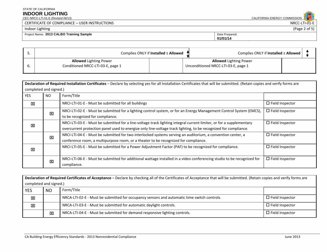
STATE OF CALIFORNIA
INDOOR LIGHTING CEC-NRCC-LTI-01-E (Revised 06/13) CALIFORNIA ENERGY COMMISSION
CERTIFICATE OF COMPLIANCE – USER INSTRUCTIONS NRCC‐LTI‐01‐E Indoor Lighting (Page 2 of 5) Project Name: 2013 CALBO Training Sample Date Prepared:
01/01/14
CA Building Energy Efficiency Standards ‐ 2013 Nonresidential Compliance June 2013
5. Complies ONLY if Installed ≤ Allowed Complies ONLY if Installed ≤ Allowed
6. Allowed Lighting Power
Conditioned NRCC‐LTI‐03‐E, page 1
Allowed Lighting Power
Unconditioned NRCC‐LTI‐03‐E, page 1
Declaration of Required Installation Certificates – Declare by selecting yes for all Installation Certificates that will be submitted. (Retain copies and verify forms are completed and signed.)
YES NO Form/Title
⌧ NRCI‐LTI‐01‐E ‐ Must be submitted for all buildings Field Inspector
⌧ NRCI‐LTI‐02‐E ‐ Must be submitted for a lighting control system, or for an Energy Management Control System (EMCS), to be recognized for compliance.
Field Inspector
⌧ NRCI‐LTI‐03‐E ‐ Must be submitted for a line‐voltage track lighting integral current limiter, or for a supplementary overcurrent protection panel used to energize only line‐voltage track lighting, to be recognized for compliance.
Field Inspector
⌧ NRCI‐LTI‐04‐E ‐ Must be submitted for two interlocked systems serving an auditorium, a convention center, a conference room, a multipurpose room, or a theater to be recognized for compliance.
Field Inspector
⌧ NRCI‐LTI‐05‐E ‐ Must be submitted for a Power Adjustment Factor (PAF) to be recognized for compliance. Field Inspector
⌧ NRCI‐LTI‐06‐E ‐ Must be submitted for additional wattage installed in a video conferencing studio to be recognized for compliance.
Field Inspector
Declaration of Required Certificates of Acceptance – Declare by checking all of the Certificates of Acceptance that will be submitted. (Retain copies and verify forms are completed and signed.)
YES NO Form/Title
⌧ NRCA‐LTI‐02‐E ‐ Must be submitted for occupancy sensors and automatic time switch controls. Field Inspector
⌧ NRCA‐LTI‐03‐E ‐ Must be submitted for automatic daylight controls. Field Inspector
⌧ NRCA‐LTI‐04‐E ‐ Must be submitted for demand responsive lighting controls. Field Inspector

STATE OF CALIFORNIA
TWO INTERLOCKED LIGHTING SYSTEMS CEC-NRCI-LTI-04-E (Revised 06/13) CALIFORNIA ENERGY COMMISSION
CERTIFICATE OF INSTALLATION NRCI‐LTI‐04‐E Two Interlocked Lighting Systems (Page 1 of 2)Project Name: 2013 CALBO Training Sample Enforcement Agency: Local Jurisdiction Permit Number: 010113
Project Address: 2013 CALBO Drive City: Sacramento Zip Code: 95814
CA Building Energy Efficiency Standards ‐ 2013 Nonresidential Compliance June 2013
GENERAL INFORMATION DATE OF BUILDING PERMIT
PERMIT #
BUILDING TYPE ⌧ Nonresidential
High‐Rise Res (Common Area) Hotel/Motel (Common Area)
PHASE OF CONSTRUCTION
⌧ New Construction Addition Alteration Unconditioned
SCOPE OF RESPONSIBILITY
Enter the date of approval by enforcement agency of the Certificate of Compliance that provides the specifications for the energy efficiency measures for the scope of responsibility for this Installation Certificate.
Date: 01/01/14
Two Interlocked Lighting Systems §130.4(b) ‐ Before Two Interlocked Lighting Systems will be permitted for compliance with §140.6 of Part 6 of Title 24, the person who is eligible under Division 3 of the Business and Professions Code to accept responsibility for the construction or installation of features, materials, components, or manufactured devices shall sign and submit this Installation Certificate. §140.6(a)1. Two interlocked lighting systems: No more than two lighting systems may be used for an area, and if there are two they must be interlocked. Where there are two interlocked lighting systems, the watts of the lower wattage system may be excluded from the actual indoor Lighting Power Density if:
A. An Installation Certificate detailing compliance with §140.6(a)1 is submitted in accordance with §10‐103 and §130.4; and
B. The area or areas served by the interlocking systems is an auditorium, a convention center, a conference room, a multipurpose room, or a theater; and
C. The two lighting systems are interlocked with a Nonprogrammable Double‐Throw Switch to prevent simultaneous operation of both systems.
If any of the following requirements fail, all installed and all planned portable lighting in the function area shall be included in the Certificates of Compliance when determining the installed lighting power. Check all that apply: ⌧ The function area qualifies to install two interlocked lighting systems because it is ONLY one of the following types:
Auditorium room Convention center room Conference room ⌧ Multipurpose room
Theater room
⌧ There are no more than two interlocked lighting systems serving the space.
⌧ The two lighting systems are interlocked with a non‐programmable double throw switch to prevent simultaneous operation.
For compliance with Part 6, a Nonprogrammable Double‐Throw Switch is an electrical switch commonly called a "single pole double throw" or "three‐way" switch that is wired as a selector switch allowing one of two loads to be enabled. It can be a line voltage switch or a low voltage switch selecting between two

STATE OF CALIFORNIA
POWER ADJUSTMENT FACTORS CEC-NRCI-LTI-05-H (Revised 06/13) CALIFORNIA ENERGY COMMISSION
CERTIFICATE OF INSTALLATION NRCI‐LTI‐05‐H Power Adjustment Factors (Page 1 of 5)Project Name: Enforcement Agency: Permit Number:
Project Address: City: Zip Code:
CA Building Energy Efficiency Standards ‐ 2013 Nonresidential Compliance June 2013
GENERAL INFORMATION DATE OF BUILDING PERMIT
PERMIT #
BUILDING TYPE Nonresidential
High‐Rise Res (Common Area) Hotel/Motel (Common Area)
PHASE OF CONSTRUCTION New Construction Addition Alteration Unconditioned
SCOPE OF RESPONSIBILITY
Enter the date of approval by enforcement agency of the Certificate of Compliance that provides the specifications for the energy efficiency measures for the scope of responsibility for this Installation Certificate:
Date:
Power Adjustment Factor (PAF) §130.4(b) ‐ Before a Power Adjustment Factor will be allowed for compliance with Section 140.6 of Part 6 of Title 24, the person who is eligible under Division 3 of the Business and Professions Code to accept responsibility for the construction or installation of features, materials, components, or manufactured devices shall sign and submit this Installation Certificate. §140.6(a) 2 ‐ Reduction of wattage through controls. In calculating actual indoor Lighting Power Density, the installed watts of a luminaire providing general lighting in an area listed in TABLE 140.6‐A may be reduced by the product of (i) the number of watts controlled as described in TABLE 140.6‐A, times (ii) the applicable Power Adjustment Factor (PAF), if all of the conditions [in this Certificate of Installation are met]: If any of the requirements in this Installation Certificate fail, the installation shall not be eligible for using the PAF. Check all that apply: PART 1 Certificate Of Compliance Correctly Filled Out
In addition to this Certificate of Installation, the PAF has been correctly document on page 2 of NRCC‐LTI‐02—E of the Certificate of Compliance submitted to the building department.
PART 2 Type of PAF
A. This installation qualifies for the following PAFs:
1. This installation qualifies for the PAF for a Partial‐ON Occupant Sensing Control in TABLE 140.6‐A because it meets all of the following requirements:
a. The Partial‐ON Occupant Sensing Control is use in only the following space types: i, An area ≤ 250 square feet enclosed by floor‐to‐ceiling partitions ii. A classroom of any size iii. A conference room of any size iv. A waiting room of any size
b. The PAF used is 0.20 c. The control automatically deactivates all of the lighting power in the area within 30 minutes after the room has been vacated; and
d. The first stage automatically activates between 30‐70 percent of the lighting power in the area e. The lighting control is a:
i. Switching system, or

STATE OF CALIFORNIA
POWER ADJUSTMENT FACTORS CEC-NRCI-LTI-05-H (Revised 06/13) CALIFORNIA ENERGY COMMISSION
CERTIFICATE OF INSTALLATION NRCI‐LTI‐05‐H Power Adjustment Factors (Page 2 of 5)Project Name: Enforcement Agency: Permit Number:
Project Address: City: Zip Code:
CA Building Energy Efficiency Standards ‐ 2013 Nonresidential Compliance June 2013
ii. Dimming system; and f. The second stage manually activates the alternate set of lights; and g. This manual‐ON function is not capable of conversion from manual‐ON to automatic‐ON functionality via manual switches or dip switches; and
h. Switches are located in accordance with Section 130.1(a) i. Occupants can manually do all of the following regardless of the sensor status:
Activate the alternate set of lights; and Activate 100 percent of the lighting power; and Deactivate all of the lights.
2. This installation qualifies for the PAF for an occupant sensing control controlling the general lighting in large open plan office areas above workstations, in accordance with TABLE 140.6‐A, because the following requirements have been met:
a. The occupant sensing controls are in large open plan offices that are greater than 250 square feet and:
i. One sensor is controlling an area that is no larger than 125 square feet, and the PAF used in 0.40
ii. One sensor is controlling an area that is from 126 to 250 square feet, and the PAF used in 0.30
iii. One sensor is controlling an area that is from 251 to 500 square feet, and the PAF used in 0.20
b. This PAF is only being applied only to office areas which contain workstations; and c. Controlled luminaires are only those which provide general lighting directly above the controlled area, or furniture mounted luminaires that comply with Section 140.6(a)2 and provide general lighting directly above the controlled area; and
d. Qualifying luminaires have been controlled by occupant sensing controls that meet all of the following requirements, as applicable:
i. Infra‐red sensors have been equipped by the manufacturer, or fitted in the field by the installer, with lenses or shrouds to prevent them from being triggered by movement outside of the controlled area.
ii. Ultrasonic sensors have been tuned to reduce their sensitivity to prevent them from being triggered by movements outside of the controlled area.
iii. All other sensors have been installed and adjusted as necessary to prevent them from being triggered by movements outside of the controlled area.
3. This installation qualifies for the PAF for a Manual Dimming System or a Multiscene Programmable Dimming System in TABLE 140.6‐A because:
a. The lighting is controlled with a control that can be manually operated by the user; and b. The space is only of the following type:
i. Hotel/motel ii. Restaurant iii. Auditorium iv. Theater
C. The type of control and PAF used is one of the following: i. A Dimming System with manual dimming and the PAF used is 0.10

STATE OF CALIFORNIA
POWER ADJUSTMENT FACTORS CEC-NRCI-LTI-05-H (Revised 06/13) CALIFORNIA ENERGY COMMISSION
CERTIFICATE OF INSTALLATION NRCI‐LTI‐05‐H Power Adjustment Factors (Page 3 of 5)Project Name: Enforcement Agency: Permit Number:
Project Address: City: Zip Code:
CA Building Energy Efficiency Standards ‐ 2013 Nonresidential Compliance June 2013
ii. A Multiscene Programmable control and the PAF used is 0.20
4. This installation qualifies for the PAF for a Demand Responsive Control in TABLE 140.6‐A, because the installation meets all of the following requirements:
i. The building is 10,000 square feet or smaller; and ii. The PAF used is 0.05. Note that luminaires that qualify for other PAFs may also qualify for this demand responsive control PAF.
iii. The controlled lighting is capable of being automatically reduced in response to a demand response signal; and
iv. Lighting has been reduced in a manner consistent with uniform level of illumination requirements in TABLE 130.1‐A; and
v. Spaces that are non‐habitable have not been used to comply with this requirement, and v. Spaces with a lighting power density of less than 0.5 watts per square foot have not been counted toward the building’s total lighting power.
5. This installation qualifies for the PAF for Combined Manual Dimming plus Partial‐ON Occupant Sensing Control in TABLE 140.6‐A because the installation meets all of the following requirements:
a. The Combined Control is use in only the following space types: i, An area ≤ 250 square feet enclosed by floor‐to‐ceiling partitions ii. A classroom of any size iii. A conference room of any size iv. A waiting room of any size
b. The lighting is controlled with a control that can be manually operated by the user; and c. The dimming component is one of the following:
i. A Dimming System with manual dimming; or ii. A Multiscene Programmable control
d. The Partial‐ON Occupant Sensing component automatically deactivates all of the lighting power in the area within 30 minutes after the room has been vacated; and
i. The first stage automatically activates between 30‐70 percent of the lighting power in the area ii. The lighting control is a:
Switching system, or Dimming system; and
iii. The second stage manually activates the alternate set of lights; and iv. This manual‐ON function is not capable of conversion from manual‐ON to automatic‐ON functionality via manual switches or dip switches; and
v. Switches are located in accordance with Section 130.1(a) vi. Occupants can manually do all of the following regardless of the sensor status:
Activate the alternate set of lights; and Activate 100 percent of the lighting power; and Deactivate all of the lights.
e. The PAF used is 0.25 PART 3 PAF Minimum Requirements Check all that apply:

STATE OF CALIFORNIA
POWER ADJUSTMENT FACTORS CEC-NRCI-LTI-05-H (Revised 06/13) CALIFORNIA ENERGY COMMISSION
CERTIFICATE OF INSTALLATION NRCI‐LTI‐05‐H Power Adjustment Factors (Page 4 of 5)Project Name: Enforcement Agency: Permit Number:
Project Address: City: Zip Code:
CA Building Energy Efficiency Standards ‐ 2013 Nonresidential Compliance June 2013
A. The lighting control used to earn the PAF is designed and installed in addition to all manual, and automatic lighting controls otherwise required in 130.1(a) through (e)
EXCEPTION. The lighting control used to earn a PAF has been designed and installed for the sole purpose of compliance with Section 130.1(b)3, and this lighting control is designed and installed in addition to all other manual, and automatic lighting controls otherwise required in Section 130.1.
B. Installed wattage has been determined in accordance with Section 130.0(c) C. Space types that qualify for the PAF comply with the definition for that space type in Section 100.1(b) D. Self contained lighting controls used to earn the PAF comply with Section 110.9 and are certified in accordance with the Appliance Efficiency Regulations, as verified on the Title 20 database of certified lighting controls
E. A lighting control system is used to earn the PAF, which complies with Section 110.9. When using a lighting control system to earn a PAF, also submit the Installation Certificate for Energy Management Control System and Lighting Control System
F. The controls are permanently installed nonresidential‐rated lighting controls. (Portable lighting, portable lighting controls, and residential rated lighting controls shall not qualify for PAFs.)
G. The controlled lighting used to earn this PAF is a permanently installed general lighting system. Furniture mounted luminaires qualify as general lighting system for the purpose of earning this PAF because the general lighting is in an office, and the furniture mounted luminaires comply with all of the following conditions: i. The furniture mounted luminaires have been permanently installed no later than the time of building permit inspection; and ii. The furniture mounted luminaires have been permanently hardwired; and iii. The furniture mounted lighting system has been designed to provide indirect general lighting; and iv. Before multiplying the installed watts of the furniture mounted luminaire by the applicable PAF, 0.3 watts per square foot of the area illuminated by the furniture mounted luminaires has been subtracted from installed watts of the furniture mounted luminaires; and
H. At least 50 percent of the light output of the controlled luminaire is within the applicable area listed in TABLE 140.6‐A. Luminaires on lighting tracks are within the applicable area in order to qualify for a PAF.
I. Only one PAF from TABLE 140.6‐A has been used for each qualifying luminaire. PAFs have not been added together unless specifically allowed in TABLE 140.6‐A.
L. Only lighting wattage directly controlled in accordance with Section 140.6(a)2 has been used to reduce the calculated actual indoor Lighting Power Densities as allowed by Section 140.6(a)2.
Only a portion of the wattage in a luminaire is controlled in accordance Section 140.6(a)2, and only that portion of controlled wattage has been reduced in calculating actual indoor Lighting Power Density.

C A L I F O R N I A E N E R G Y C O M M I S S I O N40
§130.1, §130.4 and the Plans ExaminerExaminer
• Still verify multi-level and h t OFF t lshut-OFF controls on
electrical plans:More spaces may req multi-More spaces may req. multilevel controls (> 0.5 W/ft2)
Many spaces will req. occupant sensors
All lightingPartial ON/OFF
• Refer to NRCC-LTI-02 as mandatory note block

STATE OF CALIFORNIA
INDOOR LIGHTING – LIGHTING CONTROLS CEC-NRCC-LTI-02-E (Revised 06/13) CALIFORNIA ENERGY COMMISSION
CERTIFICATE OF COMPLIANCE NRCC‐LTI‐02‐E Indoor Lighting ‐ Lighting Controls (Page 1 of 5) Project Name: 2013 CALBO Training Sample Date Prepared: 01/01/14
Registration Number: Registration Date/Time: HERS Provider: CA Building Energy Efficiency Standards ‐ 2013 Nonresidential Compliance June 2013
The NRCC‐LTI‐02‐E shall be used to document all mandatory and prescriptive lighting controls that are applicable to the project. A. Mandatory Lighting Control Declaration Statements
Indicate if the measure applies:
YES NO Control Requirements
⌧ Lighting shall be controlled by self‐contained lighting control devices which are certified to the Energy Commission according to the Title 20 Appliance Efficiency Regulations in accordance with Section 110.9.
⌧ Lighting shall be controlled by a lighting control a system or energy management control system in accordance with §110.9. An Installation Certificate shall be submitted in accordance with Section 130.4(b).
⌧ One or more Track Lighting Integral Current Limiters shall be installed which have been certified to the Energy Commission in accordance with §110.9 and §130.0. An Installation Additionally, an Installation Certificate shall be submitted in accordance with Section 130.4(b).
⌧ A Track Lighting Supplementary Overcurrent Protection Panel shall be installed in accordance with Section 110.9 and Section 130.3. Additionally, an Installation Certificate shall be installed in accordance with Section 130.4(b).
⌧ All lighting controls and equipment shall comply with the applicable requirements in §110.9 and shall be installed in accordance with the manufacturer's instructions in accordance with Section 130.1.
⌧ All luminaires shall be functionally controlled with manually switched ON and OFF lighting controls in accordance with Section 130.1(a).
⌧ General lighting shall be separately controlled from all other lighting systems in an area. Floor and wall display, window display, case display, ornamental, and special effects lighting shall each be separately controlled on circuits that are 20 amps or less. When track lighting is used, general, display, ornamental, and special effects lighting shall each be separately controlled; in accordance with Section 130.0(a)4.
⌧ The general lighting of any enclosed area 100 square feet or larger, with a connected lighting load that exceeds 0.5 watts per square foot shall meet the multi‐level lighting control requirements in accordance with Section 130.1(b).
⌧ All installed indoor lighting shall be equipped with controls that meet the applicable Shut‐OFF control requirements in Section 130.1(c).
⌧ Lighting in all Daylit Zones shall be controlled in accordance with the requirements in Section 130.1(d) and daylit zones are shown on the plans.
⌧ Lighting power in buildings larger than 10,000 square feet shall be capable of being automatically reduced in response to a Demand Responsive Signal in accordance with Section 130.1(e).

STATE OF CALIFORNIA
INDOOR LIGHTING – LIGHTING CONTROLS CEC-NRCC-LTI-02-E (Revised 06/13) CALIFORNIA ENERGY COMMISSION
CERTIFICATE OF COMPLIANCE NRCC‐LTI‐02‐E Indoor Lighting ‐ Lighting Controls (Page 2 of 5) Project Name: 2013 CALBO Training Sample Date Prepared: 01/01/14
Registration Number: Registration Date/Time: HERS Provider: CA Building Energy Efficiency Standards ‐ 2013 Nonresidential Compliance June 2013
⌧
Before an occupancy permit is granted for a newly constructed building or area, or a new lighting system serving a building, area, or site is operated for normal use, indoor lighting controls serving the building, area, or site shall be certified as meeting the Acceptance Requirements for Code Compliance in accordance with Section 130.4.(a). The controls required to meet the Acceptance Requirements include automatic daylight controls, automatic shut‐OFF controls, and demand responsive controls.
A separate document must be filled out for Conditioned and Unconditioned Spaces. This page is used only for the following:⌧ CONDITIONED SPACES UNCONDITIONED SPACES
MANDATORY AND PRESCRIPTIVE INDOOR LIGHTING CONTROL SCHEDULE, PAF CALCULATION, and FIELD INSPECTION CHECKLIST
Lighting Control Schedule
Standards Complying With 1
( all that apply, or enter ‘E’ if Exempted) PAF Credit Calculation 2
if Acceptance
Test Required
Field Inspector
Watts of
Controlled Lighting
PAF
Control Credit(K
xL)
A B C D E F G H I J K L M N O
Location in Building
Type/ Description of Lighting Control (i.e.: occupancy sensor,
automatic time switch, dimmer, automatic daylight,
etc…)
# of
Units §130.1(a)
§130.0(b)
§130.1(c)
§130.1(d)
§130.1(e)
§140.6(a)2
§140.6(d)
Pass
Fail
Lobby area Continuous dimming 3 √ √ N/A N/A N/A √ Corridor 1 Occupancy Sensor 2 √ √ N/A N/A N/A √

C A L I F O R N I A E N E R G Y C O M M I S S I O N41
§130.1, §130.4 and the Field InspectorInspector
• At Final verify:Multi level lighting controlsMulti-level lighting controls installed in accordance with TABLE 130.1-A
Sh OFF l i ll dShut-OFF controls installed to comply with completely OFF, or Partial ON/OFF requirements
• Verify req. NRCI-LTI forms
• Verify req. NRCA-LTI formsMust be signed my CLCATTwhen req. * Refer to NRCA-LTI-02

STATE OF CALIFORNIA
AUTOMATIC DAYLIGHTING CONTROL ACCEPTANCE DOCUMENT CEC-NRCA-LTI-03-A (Revised 06/13) CALIFORNIA ENERGY COMMISSION
CERTIFICATE OF ACCEPTANCE NRCA‐LTI‐02‐A Lighting Control Acceptance Document (Page 1 of 6)Project Name: Enforcement Agency: Permit Number:
Project Address: City: Zip Code:
CA Building Energy Efficiency Standards ‐ 2013 Nonresidential Compliance June 2013
Note: For more than 3 spaces attach additional sets of pages 2 through 5, as required.
Enforcement Agency Use: Checked by/Date
Automatic Shut‐off Controls: Automatic Time Switch Control and Occupant Sensor Intent: Lights are turned off or set to a lower level when not needed per Section 110.9(a) & 130.1(c).
Guidance This acceptance test form must be filled out for all newly‐installed lighting control systems of the following types:
I. Automatic Time Switch Controls II. Occupancy Sensors III. Partial‐OFF occupancy sensors IV. Partial‐ON occupancy sensors (only if used to claim a Power Adjustment Factor) V. Occupancy Sensors serving small zones in large open plan offices (only if used to claim a Power Adjustment Factor)
For automatic daylighting controls use acceptance test form NRCA‐LTI‐03‐A; for demand responsive lighting controls, use acceptance test form NRCA‐LTI‐04‐A. The tests on this certificate are required by Section 140.6(a)2 and 130.4(a) of the Building Energy Efficiency Standards 2013. The tests themselves are described in Sections 140.6(a)2 and in Reference Appendix NA7.6.
A. Construction Inspection Fill out Section A to cover spaces 1 through 3 that are functionally tested under Section B. Make as many copies of pages 2‐5 as are required to test all spaces in the building, and attach to page 1.
Instruments needed to perform tests include, but are not limited to: hand‐held amperage meter, power meter, or light meter 1 Automatic Time Switch Controls Construction Inspection—confirm for all listed in Section B a. All automatic time switch controls are programmed for (check all): � Weekdays
� Weekend
� Holidays
b. Document for the owner automatic time switch programming (check all):
� Weekdays settings
� Weekend settings
� Holidays settings
� Set‐up settings
� Preference program setting
� Verify the correct time and date is properly set in the time switch
� Verify the battery is installed and energized
� Override time limit is no more than 2 hours
� Occupant Sensors and Automatic Time Switch Controls have been certified to the Energy Commission in accordance with the applicable provision in Section 110.9 of the Standards, and model numbers for all such controls are listed on the Commission database as Certified Appliance and Control Devices
2 Occupancy Sensor Construction Inspection—confirm for all listed in Section B

STATE OF CALIFORNIA
AUTOMATIC DAYLIGHTING CONTROL ACCEPTANCE DOCUMENT CEC-NRCA-LTI-03-A (Revised 06/13) CALIFORNIA ENERGY COMMISSION
CERTIFICATE OF ACCEPTANCE NRCA‐LTI‐02‐A Lighting Control Acceptance Document (Page 2 of 6)Project Name: Enforcement Agency: Permit Number:
Project Address: City: Zip Code:
CA Building Energy Efficiency Standards ‐ 2013 Nonresidential Compliance June 2013
� Occupancy sensors are not located within four feet of any HVAC diffuser
� Ultrasonic occupancy sensors do not emit audible sound 5 feet from source
B. Functional Testing of Lighting Controls Representative Spaces Selected For every space in the building, conduct functional tests I through V below if applicable. If there are several geometrically similar spaces that use the same lighting controls, test only one space and list in the cells below which “untested spaces” are represented by that tested space. EXCEPTION: For buildings with up to seven (7) occupancy sensors, all occupancy sensors shall be tested. (NA7.6.2.3)
� 1 Tested space/ room name:________________________ Space Type (office, corridor, etc)___________________ Untested areas/rooms ________________________________________________________________________
� 2 Tested space/ room name:________________________ Space Type (office, corridor, etc)___________________ Untested areas/rooms ________________________________________________________________________
� 3 Tested space/ room name:________________________ Space Type (office, corridor, etc)___________________ Untested areas/rooms ________________________________________________________________________
Functional Tests Tested Space Number
Confirm compliance (Y/N) for all control system types (I‐V) present in each space:
1. Automatic Time Switch Controls 1 2 3
Step 1: Simulate occupied condition
a. All lights can be turned on and off by their respective area control switch Y / N Y / N Y / N
b. Verify the switch only operates lighting in the ceiling‐height partitioned area in which the switch is located
Y / N Y / N Y / N
Step 2: Simulate unoccupied condition
a. All lighting, including emergency and egress lighting, turns off. Exempt lighting may remain on per Section 130.1(c)1 and 130,1(a)1.
Y / N Y / N Y / N
b. Manual override switch allows only the lights in the selected ceiling height partitioned space where the override switch is located and remain on no longer than 2 hours (unless serving public areas and override switch is captive key type).
Y / N Y / N Y / N
Step 3: System returned to initial operating conditions Y / N Y / N Y / N
2. Occupancy Sensors 1 2 3
Step 1: Simulate an unoccupied condition
a. Lights controlled by occupancy sensors turn off within a maximum of 30 minutes from start of an unoccupied condition per Standard Section 110.9(a)
Y / N Y / N Y / N
b. The occupant sensor does not trigger a false "on" from movement in an area adjacent to the controlled space or from HVAC operation
Y / N Y / N Y / N
Step 2: Simulate an occupied condition
a. Status indicator or annunciator operates correctly Y / N Y / N Y / N

STATE OF CALIFORNIA
AUTOMATIC DAYLIGHTING CONTROL ACCEPTANCE DOCUMENT CEC-NRCA-LTI-03-A (Revised 06/13) CALIFORNIA ENERGY COMMISSION
CERTIFICATE OF ACCEPTANCE NRCA‐LTI‐02‐A Lighting Control Acceptance Document (Page 3 of 6)Project Name: Enforcement Agency: Permit Number:
Project Address: City: Zip Code:
CA Building Energy Efficiency Standards ‐ 2013 Nonresidential Compliance June 2013
b. Lights controlled by occupancy sensors turn on immediately upon an occupied condition OR sensor indicates space is "occupied" and lights may be turned on manually
Y / N Y / N Y / N
Step 3: System returned to initial operating conditions Y / N Y / N Y / N

STATE OF CALIFORNIA
AUTOMATIC DAYLIGHTING CONTROL ACCEPTANCE DOCUMENT CEC-NRCA-LTI-03-A (Revised 06/13) CALIFORNIA ENERGY COMMISSION
CERTIFICATE OF ACCEPTANCE NRCA‐LTI‐02‐A Lighting Control Acceptance Document (Page 4 of 6)Project Name: Enforcement Agency: Permit Number:
Project Address: City: Zip Code:
CA Building Energy Efficiency Standards ‐ 2013 Nonresidential Compliance June 2013
3. Partial Off Occupancy Sensor 1 2 3
Step 1: Simulate an unoccupied condition
a. Lights go to partial off state within a maximum of 30 minutes from start of an unoccupied condition per Standard Section 110.9(a)
Y / N Y / N Y / N
b.
The occupant sensor does not trigger a false "on" from movement in an area adjacent to the controlled space or from HVAC operation. For library book stacks or warehouse aisle, activity beyond the stack or aisle shall not activate the lighting in the aisle or stack.
Y / N Y / N Y / N
c.
In the partial off state, lighting shall consume no more than 50% of installed lighting power, or:
• No more than 60% of installed lighting power for metal halide or high pressure sodium lighting in warehouses.
• No more than 60% of installed lighting power for corridors and stairwells in which the installed lighting power is 80 percent or less of the value allowed under the Area Category Method.
Light level may be used as a proxy for lighting power when measurements are taken
Y/N Y / N Y / N
Step 2: Simulate an occupied condition
a. The occupant sensing controls shall turn lights fully ON in each separately controlled areas, Immediately upon an occupied condition
Y / N Y / N Y / N
4. Partial On Occupancy Sensors 1 2 3
Step 1. ‐Simulate an occupied condition. Verify partial on operation.
a. Immediately upon an occupied condition, the first stage activates between 30 to 70% of the lighting automatically.
Y / N Y / N Y / N
b. After the first stage occurs, manual switches allow an occupant to activate the alternate set of lights, activate 100% of the lighting power, and manually deactivate all of the lights.
Y / N Y / N Y / N
Step 2. Simulate an unoccupied condition
a. Both stages (automatic on and manual on) lights turn off within a maximum of 30 minutes from start of an unoccupied condition per Standard Section 110.9(a)
Y / N Y / N Y / N
b. The occupant sensor does not trigger a false "on" from movement in an area adjacent to the controlled space or from HVAC operation
Y / N Y / N Y / N
5. Additional test for Occupancy Sensors Serving Small Zones in Office Spaces Larger than 250 Square Feet, to Qualify for a Power Adjustment Factor (PAF)
1 2 3
First, complete Functional Test 2 (above ) for each controlled zone
Step 1. Verify area served and compare actual PAF with claimed PAF. Refer to Functional Test II.
a. Area served by controlled lighting (square feet)
b. Enter PAF corresponding to controlled area from line (a) above (<125sf for PAF=0.4, 126‐250sf for PAF=0.3, 251‐500sf for PAF=0.2).
c. Enter PAF claimed for occupant sensor control in this space from the Certificate of Compliance
d. The PAF corresponding to the controlled area (line b), is less than or equal to the PAF claimed in the compliance documentation (line c)
Y / N Y / N Y / N
e. Sensors shall not trigger in response to movement in adjacent walkways or workspaces.
Y / N Y / N Y / N

STATE OF CALIFORNIA
AUTOMATIC DAYLIGHTING CONTROL ACCEPTANCE DOCUMENT CEC-NRCA-LTI-03-A (Revised 06/13) CALIFORNIA ENERGY COMMISSION
CERTIFICATE OF ACCEPTANCE NRCA‐LTI‐02‐A Lighting Control Acceptance Document (Page 5 of 6)Project Name: Enforcement Agency: Permit Number:
Project Address: City: Zip Code:
CA Building Energy Efficiency Standards ‐ 2013 Nonresidential Compliance June 2013
f. All steps are conducted in Functional Test 2 “Occupancy Sensor (On Off Control)” and all answers are Yes (Y)
Y / N Y / N Y / N
C Testing Results PASS / FAIL
PASS / FAIL
PASS / FAIL
I Automatic Time Switch Controls (all answers must be Y). Pass II Occupancy Sensor (On Off Control) (all answers must be Y). Pass III Partial Off Occupancy Sensor (all answers must be Y). For warehouses, library book stacks, corridors, stairwells in nonresidential buildings must also be accompanied by passing Test I or Test II.
Pass
IV Partial On Occupant Sensor for PAF (all answers must be Y). Pass V Occupant Sensor serving small zones for PAF (all answers must be Y). Also must pass Test II
N/A
D. Evaluation :
⌧ PASS: All applicable Construction Inspection responses are complete and all applicable Equipment Testing Requirementsresponses are positive (Y ‐ yes)

STATE OF CALIFORNIA
AUTOMATIC DAYLIGHTING CONTROL ACCEPTANCE DOCUMENT CEC-NRCA-LTI-03-A (Revised 06/13) CALIFORNIA ENERGY COMMISSION
CERTIFICATE OF ACCEPTANCE NRCA‐LTI‐02‐A Lighting Control Acceptance Document (Page 6 of 6)Project Name: Enforcement Agency: Permit Number:
Project Address: City: Zip Code:
CA Building Energy Efficiency Standards ‐ 2013 Nonresidential Compliance June 2013
Documentation author’s Declaration Statement
1. I certify that this Certificate of Acceptance documentation is accurate and complete. Documentation Author Name: Documentation Author Signature:
Documentation Author Company Name: Date Signed:
Address: CEA/HERS/ATT Certification Identification (If applicable):
City/State/Zip: Phone:
FIELD TECHNICIAN'S DECLARATION STATEMENT
I certify the following under penalty of perjury, under the laws of the State of California:
1. The information provided on this Certificate of Acceptance is true and correct.
2. I am the person who performed the acceptance verification reported on this Certificate of Acceptance (Field Technician).
3. The construction or installation identified on this Certificate of Acceptance complies with the applicable acceptance requirements indicated in the plans and specifications approved by the enforcement agency, and conforms to the applicable acceptance requirements and procedures specified in Reference Nonresidential Appendix NA7.
4. I have confirmed that the Certificate(s) of Installation for the construction or installation identified on this Certificate of Acceptance has been completed and signed by the responsible builder/installer and has been posted or made available with the building permit(s) issued for the building.
Field Technician Name: Field Technician Signature:
Field Technician Company Name: Position with Company (Title):
Address: ATT Certification Identification (if applicable):
CALCTP Cert.#: 010113-15 City/State/Zip: Phone: Date Signed:
RESPONSIBLE PERSON'S DECLARATION STATEMENT
I certify the following under penalty of perjury, under the laws of the State of California:
1. I am the Field Technician, or the Field Technician is acting on my behalf as my employee or my agent and I have reviewed the information provided on this Certificate of Acceptance.
2. I am eligible under Division 3 of the Business and Professions Code in the applicable classification to accept responsibility for the system design, construction or installation of features, materials, components, or manufactured devices for the scope of work identified on this Certificate of Acceptance and attest to the declarations in this statement (responsible acceptance person).
3. The information provided on this Certificate of Acceptance substantiates that the construction or installation identified on this Certificate of Acceptance complies with the acceptance requirements indicated in the plans and specifications approved by the enforcement agency, and conforms to the applicable acceptance requirements and procedures specified in Reference Nonresidential Appendix NA7.
4. I have confirmed that the Certificate(s) of Installation for the construction or installation identified on this Certificate of Acceptance has been completed and is posted or made available with the building permit(s) issued for the building.
5. I will ensure that a completed, signed copy of this Certificate of Acceptance shall be posted, or made available with the building permit(s) issued for the building, and made available to the enforcement agency for all applicable inspections. I understand that a signed copy of this Certificate of Acceptance is required to be included with the documentation the builder provides to the building owner at occupancy.
Responsible Acceptance Person Name: Responsible Acceptance Person Signature:
Responsible Acceptance Person Company Name: Position with Company (Title):
Address: CSLB License:
City/State/Zip: Phone: Date Signed:

C A L I F O R N I A E N E R G Y C O M M I S S I O N42
Electrical Power DistributionN d t i t i §130 5• New mandatory requirements in §130.5
• Requirements for:Service metering
TABLE 130.5-A
Disaggregation of electrical circuitsTABLE 130.5-B
V lt DVoltage Drop
120-Volt Receptacles
D d R i lDemand Responsive controls
EMCS

2013 Building Energy Efficiency Standards Page 144
SECTION 130.5 –ELECTRICAL POWER DISTRIBUTION SYSTEMS
(c) When certification is required by Title 24, Part 1, Section 10-103-A, the acceptance testing specified by Section 130.4 shall be performed by a Certified Lighting Controls Acceptance Test Technician (CLCATT). If the CLCATT is operating as an employee, the CLCATT shall be employed by a Certified Lighting Controls Acceptance Test Employer. The CLCATT shall disclose on the Certificate of Acceptance a valid CLCATT certification identification number issued by an approved Acceptance Test Technician Certification Provider. The CLCATT shall complete all Certificate of Acceptance documentation in accordance with the applicable requirements in Section 10-103(a)4.
NOTE: Authority cited: Sections 25402, 25402.1, 25213, Public Resources Code. Reference: Sections 25007, 25402(a)-(b), 25402.1, 25402.4, 25402.5, 25402.8 and 25910, Public Resources Code.
SECTION 130.5 –ELECTRICAL POWER DISTRIBUTION SYSTEMS (a) Service Metering. Each electrical service shall have permanently installed user-accessible metering of total electrical
energy use per TABLE 130.5-A.
(b) Disaggregation of Electrical Circuits. Electrical power distribution systems shall be designed to permit the disaggregated measurement of electrical load energy uses downstream from the service meter according to TABLE 130.5-B. Additive and subtractive methods may be used to determine aggregate and disaggregated energy use. This may be accomplished by any of the following methods:
1. Separate switchboards, motor control centers, or panelboards to which are connected only the required load or group of loads; or
2. Subpanels of the above to which are connected only the required load or group of loads and for which the subpanel load can be independently measured in aggregate; or
3. Branch circuits, taps or disconnects requiring overcurrent protection devices rated 60 amperes or greater.
EXCEPTION to Section 130.5(a) Buildings for which the utility company provides a meter for occupant or user use that indicates instantaneous kW demand and kWh for a user-resettable period.
EXCEPTION to Section 130.5(a) Buildings for which the utility company provides a meter for occupant or user use that indicates instantaneous kW demand and kWh for a user-resettable period.
EXCEPTION 1 to Section 130.5(b) Buildings for which a complete metering and measurement system is provided that at a minimum measures and reports the loads called for in TABLE 130.5-B.
EXCEPTION 2 to Section 130.5(b) Alterations where all of the following conditions exist are not required to comply with this section:
A. The following existing equipment remains in place:
i. Service distribution switchboards or panelboards; and
ii. Feeders; and
iii. Motor control centers or panelboards.
B. Existing equipment included in Item A (above) remains unaltered except for:
i. Changes to load circuit connections; or
ii. Changes to the quantity of outgoing overcurrent protection devices; or
iii. Changes to the ampacity of outgoing overcurrent protection devices.
(c) Voltage Drop
1. Feeders. Feeder conductors shall be sized for a maximum voltage drop of 2 percent at design load.
2. Branch Circuits. Branch circuit conductors shall be sized for a maximum voltage drop of 3 percent at design load.
EXCEPTION to Section 130.5(c): Feeder conductors and branch circuits that are dedicated to emergency services.

2013 Building Energy Efficiency Standards Page 145
SECTION 130.5 –ELECTRICAL POWER DISTRIBUTION SYSTEMS
(d) Circuit Controls for 120-Volt Receptacles. In all buildings, both controlled and uncontrolled 120 volt receptacles shall be provided in each private office, open office area, reception lobby, conference room, kitchenette in office spaces, and copy room. Additionally, hotel/motel guest rooms shall comply with Item 5. Controlled receptacles shall meet the following requirements, as applicable:
1. Electric circuits serving controlled receptacles shall be equipped with automatic shut-OFF controls following the requirements prescribed in Section 130.1(c)(1 through 5); and
2. At least one controlled receptacle shall be installed within 6 feet from each uncontrolled receptacle or a split-wired duplex receptacle with one controlled and one uncontrolled receptacle shall be installed; and
3. Controlled receptacles shall have a permanent marking to differentiate them from uncontrolled receptacles; and
4. For open office areas, controlled circuits shall be provided and marked to support installation and configuration of office furniture with receptacles that comply with Section 130.5(d) 1, 2, and 3; and
5. For hotel and motel guest rooms at least one-half of the 120-volt receptacles in each guest room shall be controlled receptacles that comply with Section 130.5(d)1, 2, and 3. Electric circuits serving controlled receptacles shall have captive card key controls, occupancy sensing controls, or automatic controls such that, no longer than 30 minutes after the guest room has been vacated, power is switched off.
6. Plug-in strips and other plug-in devices that incorporate an occupant sensor shall not be used to comply with this requirement.
EXCEPTION 1 to Section 130.5(d): In open office areas, controlled circuit receptacles are not required if, at time of final permit, workstations are installed, and each workstation is equipped with an occupant sensing control that is permanently mounted in each workstation, and which controls a hardwired, nonresidential-rated power strip. Plug-in strips and other plug-in devices that incorporate an occupant sensor shall not be used for this exception.
EXCEPTION 2 to Section 130.5(d): Receptacles that are only for the following purposes:
i. Receptacles specifically for refrigerators and water dispensers in kitchenettes.
ii. Receptacles located a minimum of six feet above the floor that are specifically for clocks.
iii. Receptacles for network copiers, fax machines, A/V and data equipment other than personal computers in copy rooms.
iv. Receptacles on circuits rated more than 20 amperes.
(e) Demand responsive controls and equipment. Demand responsive controls and equipment shall be capable of receiving and automatically responding to at least one standards based messaging protocol which enables demand response after receiving a demand response signal.
(f) Energy Management Control System (EMCS).
1. An EMCS may be installed to comply with the requirements of one or more lighting controls if it meets the following minimum requirements:
A. Provides all applicable functionality for each specific lighting control or system for which it is installed in accordance with Section 110.9; and
B. Complies with all applicable Lighting Control Installation Requirements in accordance with Section 130.4 for each specific lighting control or system for which it is installed; and
C. Complies with all applicable application requirements for each specific lighting control or system for which it is installed, in accordance with Part 6.
2. An EMCS may be installed to comply with the requirements of a thermostat if it complies with all applicable application requirements for each thermostat in accordance with Part 6.

2013 Building Energy Efficiency Standards Page 146
SECTION 130.5 –ELECTRICAL POWER DISTRIBUTION SYSTEMS
TABLE 130.5-A MINIMUM REQUIREMENTS FOR METERING OF ELECTRICAL LOAD
Meter Type Services rated 50 kVA or less
Services rated more than 50kVA and less than or equal to 250
kVA
Services rated more than 250 kVA and less than or
equal to 1000kVA
Services rated more than 1000kVA
Instantaneous (at the time) kW demand Required Required Required Required
Historical peak demand (kW) Not required Not required Required Required
Resettable kWh Required Required Required Required
kWh per rate period Not required Not required Not required Required

2013 Building Energy Efficiency Standards Page 147
SECTION 130.5 –ELECTRICAL POWER DISTRIBUTION SYSTEMS
TABLE 130.5-B MINIMUM REQUIREMENTS FOR SEPARATION OF ELECTRICAL LOAD
Load Type Services rated 50 kVA or less
Services rated more than 50kVA and
less than or equal to 250 kVA
Services rated more than 250 kVA and less than or
equal to 1000kVA
Services rated more than 1000kVA
Lighting including exit and egress lighting and exterior lighting
Not required All lighting in aggregate
All lighting disaggregated by floor, type or area
All lighting disaggregated by floor, type or area
HVAC systems and components including chillers, fans, heaters, furnaces, package units, cooling towers, and circulation pumps associated with HVAC
Not required All HVAC in aggregate
All HVAC in aggregate and each HVAC load rated at
least 50 kVA
All HVAC in aggregate and each HVAC load rated at least 50kVA
Domestic and service water system pumps and related systems and components
Not required All loads in aggregate All loads in aggregate All loads in aggregate
Plug load including appliances rated less than 25 kVA
Not required
All plug load in aggregate
Groups of plug loads exceeding 25 kVA
connected load in an area less than 5000 sf
All plug load separated by floor, type or area
Groups of plug loads exceeding 25 kVA
connected load in an area less than 5000 sf
All plug load separated by floor, type or area
All groups of plug loads exceeding 25 kVA connected load
in an area less than 5000 sf
Elevators, escalators, moving walks and transit systems
Not required All loads in aggregate All loads in aggregate All loads in aggregate
Other individual nonHVAC loads or appliances rated 25kVA or greater
Not required All Each Each
Industrial and commercial load centers 25 kVA or greater including theatrical lighting installations and commercial kitchens
Not required All Each Each
Renewable power source (net or total) Each group Each group Each group Each group
Loads associated with renewable power source Not required All loads in
aggregate All loads in aggregate All loads in aggregate
Charging stations for electric vehicles
All loads in aggregate
All loads in aggregate All loads in aggregate All loads in aggregate

C A L I F O R N I A E N E R G Y C O M M I S S I O N43
§130.5 and the Plans ExaminerExaminer
• Verify specifications on NRCC ELC 01 formNRCC-ELC-01 form
Service metering
Di ti f i itDisaggregation of circuits
Voltage drop
120 lt t l120 volt receptacles
• Form must be on plans
• Must be registered starting 1/1/15

STATE OF CALIFORNIA
Electrical Power Distribution CEC-NRCC-ELC-01-E (Revised 06/13) CALIFORNIA ENERGY COMMISSION
CERTIFICATE OF COMPLIANCE NRCC‐ELC‐01‐E Electrical Power Distribution (Page 1 of 8)Project Name: 2013 CALBO Training Sample Date Prepared: 01/01/14
CA Building Energy Efficiency Standards ‐ 2013 Nonresidential Compliance June 2013
Project Address: 2013 CALBO Drive
Climate Zone: 12
Conditioned Floor Area : 5,000 ft2 Unconditioned Floor Area :
General Information Building Type: ⌧
Nonresidential High-Rise Residential Hotel/Motel
Schools Relocatable Public Schools
⌧ Conditioned Spaces Unconditioned Spaces
Phase of Construction: ⌧ New Construction Addition Alteration
1. I certify that this Certificate of Compliance documentation is accurate and complete. Documentation Author Name: Documentation Author Signature:
Company: Signature Date:
Address: CEA/ HERS Certification Identification (if applicable):
City/State/Zip: Phone:
RESPONSIBLE PERSON'S DECLARATION STATEMENT
I certify the following under penalty of perjury, under the laws of the State of California: 1. The information provided on this Certificate of Compliance is true and correct. 2. I am eligible under Division 3 of the Business and Professions Code to accept responsibility for the building design or system design
identified on this Certificate of Compliance (responsible designer). 3. The energy features and performance specifications, materials, components, and manufactured devices for the building design or system
design identified on this Certificate of Compliance conform to the requirements of Title 24, Part 1 and Part 6 of the California Code of Regulations.
4. The building design features or system design features identified on this Certificate of Compliance are consistent with the information provided on other applicable compliance documents, worksheets, calculations, plans and specifications submitted to the enforcement agency for approval with this building permit application.
5. I will ensure that a completed signed copy of this Certificate of Compliance shall be made available with the building permit(s) issued for the building, and made available to the enforcement agency for all applicable inspections. I understand that a completed signed copy of this Certificate of Compliance is required to be included with the documentation the builder provides to the building owner at occupancy.
Responsible Designer Name: Responsible Designer Signature:
Company : Date Signed:
Address: License:
City/State/Zip: Phone:

STATE OF CALIFORNIA
Electrical Power Distribution CEC-NRCC-ELC-01-E (Revised 06/13) CALIFORNIA ENERGY COMMISSION
CERTIFICATE OF COMPLIANCE NRCC‐ELC‐01‐E Electrical Power Distribution (Page 2 of 8)Project Name: 2013 CALBO Training Sample Date Prepared: 01/01/14
CA Building Energy Efficiency Standards ‐ 2013 Nonresidential Compliance June 2013
A. Electrical Service Metering ⌧ Each newly installed electrical service (in both existing and newly constructed buildings) is required to be metered, as set out in Table 130.5-A, which is reproduced below. ⌧ Fill out a separate line for each electrical service that is connected to the building.
Electrical Service Schedule
Electrical Service Rating
Metering Capabilities (check all that are present) Field
Inspector
A B C D E F G
Designation/location in building/description kVA
Instantaneous (at the tim
e) kW
demand
Historical peak
demand
(kW)
Resettable
kWh
kWh per rate period
Pass
Fail
Office Space 500 ⌧ ⌧ ⌧
Warehouse Area 250 ⌧ ⌧
Table 130.5-A - MINIMUM REQUIREMENTS FOR METERING OF ELECTRICAL LOAD
Meter Rating (kVA) 50 kVA or less
More than 50kVA and less than or equal to 250 kVA
More than 250 kVA and less than or equal to 1000kVA
Services rated more than 1000kVA
Instantaneous (at the time) kW demand
Required Required Required Required
Historical peak demand (kW)
Not required Not required Required Required
Resettable kWh Required Required Required Required kWh per rate period Not required Not required Not required Required

STATE OF CALIFORNIA
Electrical Power Distribution CEC-NRCC-ELC-01-E (Revised 06/13) CALIFORNIA ENERGY COMMISSION
CERTIFICATE OF COMPLIANCE NRCC‐ELC‐01‐E Electrical Power Distribution (Page 3 of 8)Project Name: 2013 CALBO Training Sample Date Prepared: 01/01/14
CA Building Energy Efficiency Standards ‐ 2013 Nonresidential Compliance June 2013
B. Disaggregation of Electrical Circuits ⌧ Each newly installed switchboard, panel, and motor control center (in both existing and newly constructed buildings) is
required to be disaggregated according to the requirements of Table 130.5-B, shown on the next page. ⌧ Individual branch circuits, taps or disconnects that require overcurrent protection devices rated 60A or greater are
exempt. ⌧ As an alternative, current transformers can be added for individual branch circuits and loads throughout the building, and
a permanent measurement system can be installed. In this case, disaggregated wiring would not be required as long as the metering system allows the equivalent disaggregated measurements.
⌧ Fill out a separate line for each switchboard, motor control center, panelboard and subpanel.

STATE OF CALIFORNIA
Electrical Power Distribution CEC-NRCC-ELC-01-E (Revised 06/13) CALIFORNIA ENERGY COMMISSION
CERTIFICATE OF COMPLIANCE NRCC‐ELC‐01‐E Electrical Power Distribution (Page 4 of 8)Project Name: 2013 CALBO Training Sample Date Prepared: 01/01/14
CA Building Energy Efficiency Standards ‐ 2013 Nonresidential Compliance June 2013
Switchboard, motor control center, panelboard or subpanel
Electrical Service that supplies that switchboard or panel
Electrical Service Rating Field Inspector
Pass Fail
A B C D
Designation/location in building/description Designation/location in building/description
kVA
Switchboard Office Space 500 Panel Board Warehouse Area 250
OR
Current transformers have been attached to individual branch circuits and loads throughout the building, and a permanent measurement system is installed that allows an equivalent degree of disaggregated measurement as required by the
Standards..

STATE OF CALIFORNIA
Electrical Power Distribution CEC-NRCC-ELC-01-E (Revised 06/13) CALIFORNIA ENERGY COMMISSION
CERTIFICATE OF COMPLIANCE NRCC‐ELC‐01‐E Electrical Power Distribution (Page 5 of 8)Project Name: 2013 CALBO Training Sample Date Prepared: 01/01/14
CA Building Energy Efficiency Standards ‐ 2013 Nonresidential Compliance June 2013
B. Disaggregation of Electrical Circuits (continued) Table 130.5-B - MINIMUM REQUIREMENTS FOR SEPARATION OF ELECTRICAL LOAD
Table 130.5 – B sets the upper limit on how many load(s) of each type can be supplied by each feeder. A feeder may not supply loads of more than one type unless the service is rated at 50 kVA or less. For instance, on the fifth row of the table, one feeder on a service >50 kVA could be used to supply all the plug loads on a floor of a building, provided that there are no areas in which more than 25kVA of plug load is supplied to a
space less than 5000sf
Load Type Services rated 50 kVA or less
Services rated more than 50kVA and less than or
equal to 250 kVA
Services rated more than 250 kVA and less than or
equal to 1000kVA Services rated more
than 1000kVA Lighting including exit and egress lighting and exterior lighting
Not required All lighting in aggregate All lighting disaggregated by floor, type or area
All lighting disaggregated by floor,
type or area HVAC systems and components including chillers, fans, heaters, furnaces, package units, cooling towers, and circulation pumps associated with HVAC
Not required All HVAC in aggregate All HVAC in aggregate and each HVAC load rated at least 50 kVA
All HVAC in aggregate and each HVAC load rated at least 50kVA
Domestic and service water system pumps and related systems and components
Not required All loads in aggregate All loads in aggregate All loads in aggregate
Plug load including appliances rated less than 25 kVA
Not required
All plug load in aggregateGroups of plug loads exceeding 25 kVA
connected load in an area less than 5000 sf
All plug load separated by floor, type or area Groups of plug loads exceeding 25 kVA
connected load in an area less than 5000 sf
All plug loads separated by floor,
type or area. All groups of plug loads
exceeding 25 kVA connected load in an area less than 5000 sf
Elevators, escalators, moving walks, and transit systems
Not required All loads in aggregate All loads in aggregate All loads in aggregate
Other individual non‐HVAC loads or appliances rated 25kVA or greater
Not required All Each Each
Industrial and commercial load centers 25 kVA or greater including theatrical lighting installations and commercial kitchens
Not required All Each Each
Renewable power source (net or total)
Each group Each group Each group Each group
Loads associated with renewable power source
Not required All loads in aggregate All loads in aggregate All loads in aggregate
Charging stations for electric vehicles
All loads in aggregate
All loads in aggregate All loads in aggregate All loads in aggregate

STATE OF CALIFORNIA
Electrical Power Distribution CEC-NRCC-ELC-01-E (Revised 06/13) CALIFORNIA ENERGY COMMISSION
CERTIFICATE OF COMPLIANCE NRCC‐ELC‐01‐E Electrical Power Distribution (Page 6 of 8)Project Name: 2013 CALBO Training Sample Date Prepared: 01/01/14
CA Building Energy Efficiency Standards ‐ 2013 Nonresidential Compliance June 2013
C. Voltage Drop ⌧ Attach voltage drop worksheet to this form, ⌧ Field inspector has discretion to approve the worksheets; the tables shown below in this section are advisory only ⌧ Feeder conductors and branch circuits that are dedicated to emergency services are exempt from these requirements. ⌧ To calculate branch circuit length, the approximate centroid of the load may be used if the actual conductor length is not
known. ⌧ When calculating branch circuit loads, receptacle loads may be derated using a load factor of 75% ⌧ An advisory table of typical power factors is shown below ⌧ Advisory tables of typical maximum feeder and branch circuit lengths are shown on the following page. Tables assume
1.0 power factor and that the circuit current is 80% of the rated value.
Field Inspector
Pass
Fail
Feeders. Feeder conductors shall be sized for a maximum voltage drop of 2 percent at design load.
Branch Circuits. Branch circuit conductors shall be sized for a maximum voltage drop of 3 percent at design load.
Compliance Manual, Chapter 8, Table 8 2: Typical Power Factors for Voltage Drop Calculations
Load Type Default Power
Factor at 120 volts Default Power
Factor at 277 volts Clarifying Notes Fluorescent lighting 0.95 0.95
Compact fluorescent lighting
0.9 (hardwired) 0.5 (GU-24)
0.9 (hardwired) 0.3 (GU-24)
NPF magnetic ballasts use GU-24 values
LED lighting 0.7 0.5 May be higher if specifications call for high power factor drivers
Incandescent lighting 1.0 1.0
HID lighting 0.9 0.9 May be lower if NPF ballasts are specified
HVAC packages 0.85 0.9 Other motors <5 HP 0.8 0.8
Other motors >5 HP 0.85 0.85
Kitchen equipment 0.9 N/A
Receptacles 0.6 N/A For dedicated receptacles, may be rated according to the load
Electric heating including hot water
1.0 1.0
Other 0.85 0.85

STATE OF CALIFORNIA
Electrical Power Distribution CEC-NRCC-ELC-01-E (Revised 06/13) CALIFORNIA ENERGY COMMISSION
CERTIFICATE OF COMPLIANCE NRCC‐ELC‐01‐E Electrical Power Distribution (Page 7 of 8)Project Name: 2013 CALBO Training Sample Date Prepared: 01/01/14
CA Building Energy Efficiency Standards ‐ 2013 Nonresidential Compliance June 2013
C. Voltage Drop (continued)
Compliance Manual, Chapter 8, Table 8 5 Voltage Drop for Common Copper Wire Gauges and Current Loads
Wire gauge
Circuit Current (Amps)
Maximum Feeder Length (feet) Maximum Branch Circuit Length (feet)
120 208 240 277 480 120 208 240 277 480 14 12 39 67 78 90 156 58 101 117 135 233 12 16 46 80 93 107 185 69 120 139 160 278 10 24 48 83 96 111 192 72 125 144 166 288 8 32 57 99 115 132 229 86 149 172 199 344 6 40 73 127 146 169 293 110 190 220 253 439 4 52 89 154 178 206 356 134 232 267 309 535 2 72 103 178 206 237 412 154 267 309 356 617 0 96 123 212 245 283 490 184 319 368 424 735
00 108 137 238 274 317 549 206 357 412 475 823 0000 144 163 283 327 377 654 245 425 490 566 980
250 (kcmil) 164 170 294 340 392 679 255 441 509 588 1019 300 184 181 314 362 418 725 272 471 543 627 1087 350 200 195 338 390 450 779 292 506 584 675 1169 500 248 224 388 448 517 896 336 582 672 776 1344
Compliance Manual, Chapter 8, Table Error! No text of specified style in document.‐1 Voltage Drop for Common Aluminum Wire Gauges and
Current Loads
Wire gauge
Circuit Curren
t (Amps
)
Maximum Feeder Length (feet)
Maximum Branch Circuit Length (feet)
120 208 240 277 480 120 208 240 277 480 14* 12 24 41 47 55 95 36 62 71 82 142 12* 16 28 49 56 65 113 42 73 85 98 169 10 24 29 51 59 68 118 44 76 88 102 176 8 32 35 61 70 81 140 53 91 105 121 210 6 40 45 77 89 103 178 67 116 134 154 267 4 52 54 94 109 126 218 82 142 163 188 327 2 72 62 108 125 144 250 94 162 187 216 375 0 96 74 129 149 172 298 112 193 223 258 446
00 108 84 145 167 193 334 125 217 251 289 501 0000 144 99 172 198 229 397 149 258 298 344 595 250
(kcmil)164 103 179 207 239 413 155 269 310 358 620
300 184 111 192 221 255 442 166 287 332 383 663 350 200 119 206 238 274 475 178 309 356 411 713 500 248 137 237 273 316 547 205 355 410 473 820

STATE OF CALIFORNIA
Electrical Power Distribution CEC-NRCC-ELC-01-E (Revised 06/13) CALIFORNIA ENERGY COMMISSION
CERTIFICATE OF COMPLIANCE NRCC‐ELC‐01‐E Electrical Power Distribution (Page 8 of 8)Project Name: 2013 CALBO Training Sample Date Prepared: 01/01/14
CA Building Energy Efficiency Standards ‐ 2013 Nonresidential Compliance June 2013
D. Circuit Controls for 120-Volt Receptacles ⌧ Controlled 120 volt receptacles shall be provided, as required by Section 130.5(d) of the Standards. ⌧ In open office areas, controlled circuit receptacles are not required if, at time of final permit, workstations are installed, and
each workstation is equipped with an occupant sensing control that is permanently mounted in each workstation, and which controls a hardwired, nonresidential-rated power strip. Plug-in strips and other plug-in devices that incorporate an occupant sensor shall not be used for this exception.
⌧ Receptacles that are only for the following purposes are exempt: -Receptacles specifically for refrigerators and water dispensers in kitchenettes. -Receptacles located a minimum of six feet above the floor that are specifically for clocks. -Receptacles for network copiers, fax machines, A/V and data equipment other than personal computers in copy rooms.
Field Inspector
Pass Fail
1. At least one controlled receptacle is installed within 6 feet of each uncontrolled receptacle, or split-wired duplex receptacles are installed, that have one controlled and one uncontrolled receptacle. This applies in all of the following spaces:
• Private offices, open office areas • Receptions and lobbies • Conference rooms • Kitchenettes in office spaces • Copy room
2. Electric circuits serving controlled receptacles are equipped with automatic shut-OFF controls following the requirements prescribed in Section 130.1(c)1 through 5 (in many cases this will mean that the receptacles are connected to the same automatic shut-OFF system as the general lighting of the space).
3. Controlled receptacles shall have a permanent marking to differentiate them from uncontrolled receptacles.
4. For open office areas, controlled circuits shall be provided and marked to support installation and configuration of office furniture with receptacles that comply with Section 130.1(a)130.5(d) 1, 2, and 3.
5. For hotel and motel guest rooms at least one-half of the 120-volt receptacles in each guest room are controlled receptacles that comply with Section 130.5(d)1, 2, and 3 (see numbers 1,2 and 3 above). Electric circuits serving controlled receptacles have captive card key controls, occupancy sensing controls, or automatic controls such that, no longer than 30 minutes after the guest room has been vacated, power is switched off.
6. Plug-in strips and other plug-in devices that incorporate an occupant sensor are not used to comply with any of these requirements.

C A L I F O R N I A E N E R G Y C O M M I S S I O N44
§130.5 and the Field InspectorInspector
• Verify at Final
Elect. services are metered
Switchboards, panels, etc. are , p ,disaggregated
Feeder and branch circuit size
120 volt receptacles when req.
• Use NRCC ELC 01 as• Use NRCC-ELC-01 as inspector checklist

C A L I F O R N I A E N E R G Y C O M M I S S I O N45
Let’s talk about the changes to the Energy Standards –
Prescriptive Measures (N t ti )(New construction)

C A L I F O R N I A E N E R G Y C O M M I S S I O N46
Cool Roofs, Fenestration, etc.2008 – §143(a)
• Cool roof reqs. dependent
2013 – §140.3(a)• Cool roofs:
on:SlopeClimate zone
Density criteria removedSolar reflectance trade-off in TABLE 140.3Climate zone
Density (lb/ft2)
• Windows/skylights must
• Windows/skylightsMust meet min. VT reqs.
Windows/skylights must meet U-factor and SHGC reqs.
• New air barrier reqs.Approved materials in TABLE 140.3-A
• Reqs. in TABLE 143-A through 143-C
.
• Reqs. in TABLE 140.3-B through 140.3-D

2013 Building Energy Efficiency Standards Page 150
SECTION 140.3 – PRESCRIPTIVE REQUIREMENTS FOR BUILDING ENVELOPES
SECTION 140.3 – PRESCRIPTIVE REQUIREMENTS FOR BUILDING ENVELOPES A building complies with this section by being designed with and having constructed and installed either: (1) envelope components that comply with each of the requirements in Subsection (a) for each individual component and the requirements of Subsection (c) where they apply; or (2) an envelope that complies with the overall requirements in Subsection (b) and the requirements of Subsection (c) where they apply.
(a) Envelope Component Approach.
1. Exterior roofs and ceilings. Exterior roofs and ceilings shall comply with each of the applicable requirements in this subsection:
A. Roofing Products. Shall meet the requirements of Section 110.8 and the applicable requirements of Subsections i through ii:
i. Nonresidential buildings:
a. Low-sloped roofs in Climate Zones 1 through 16 shall have:
1. A minimum aged solar reflectance of 0.63 and a minimum thermal emittance of 0.75; or
2. A minimum Solar Reflectance Index (SRI) of 75.
EXCEPTION 1 to Section 140.3(a)1Aia: Wood-framed roofs in Climate Zones 3 and 5 are exempt from the requirements of Section 140.3(a)1Aia if the roof assembly has a U-factor of 0.039 or lower.
EXCEPTION 2 to Section 140.3(a)1Aia: Metal building roofs in Climate Zones 3 and 5 are exempt from the requirements if the roof assembly has a U-factor of 0.048 or lower.
EXCEPTION 3 to Section 140.3(a)1Aia: Roof constructions that have thermal mass with a weight of at least 25 lb/ft² over the roof membrane are exempt from the requirements of Section 140.3(a)1Aia.
EXCEPTION 4 to SECTION 140.3(a)1Aia: An aged solar reflectance less than 0.63 is allowed provided the maximum roof/ceiling U-factor in TABLE 140.3 is not exceeded.
b. Steep-sloped roofs in Climate Zones 1 through 16 shall have a minimum aged solar reflectance of 0.20 and a minimum thermal emittance of 0.75, or a minimum SRI of 16.
ii. High-rise residential buildings and hotels and motels:
a. Low-sloped roofs in Climate Zones 10, 11, 13, 14 and 15 shall have a minimum aged solar reflectance of 0.55 and a minimum thermal emittance of 0.75, or a minimum SRI of 64.
EXCEPTION to Section 140.3(a)1Aiia: Roof constructions that have thermal mass with a weight of at least 25 lb/ft² over the roof membrane .
b. Steep-sloped roofs in Climate Zones 2 through 15 shall have a minimum aged solar reflectance of 0.20 and a minimum thermal emittance of 0.75, or a minimum SRI of 16.

2013 Building Energy Efficiency Standards Page 151
SECTION 140.3 – PRESCRIPTIVE REQUIREMENTS FOR BUILDING ENVELOPES
TABLE 140.3 ROOF/CEILING INSULATION TRADEOFF FOR AGED SOLAR REFLECTANCE
Nonresidential
Aged Solar Reflectance
Metal Building Climate Zone
1-16
U-factor
Wood framed and Other
Climate Zone
1 &5
U-factor
Wood Framed and Other
Climate Zone
2-4, 9-16
U-factor
Wood Framed and Other,
Climate Zone
6
U-factor
Wood Framed and Other
Climate Zone
7 & 8
U-factor
0.62-0.60 0.061 0.045 0.036 0.065 0.059
0.59-0.55 0.054 0.041 0.034 0.058 0.053
0.54-0.50 0.049 0.038 0.032 0.052 0.048
0.49-0.45 0.047 0.035 0.030 0.047 0.044
0.44-0.40 0.043 0.033 0.028 0.043 0.040
0.39-0.35 0.039 0.031 0.027 0.039 0.037
0.34-0.30 0.035 0.029 0.025 0.037 0.035
0.29-0.25 0.033 0.027 0.024 0.034 0.032
EXCEPTION to Section 140.3(a)1A: Roof area covered by building integrated photovoltaic panels and building integrated solar thermal panels are not required to meet the minimum requirements for solar reflectance, thermal emittance, or SRI.
B. Roof Insulation. Roofs shall have an overall assembly U-factor no greater than the applicable value in TABLE 140.3-B, C or D, and where required by Section 110.8(e), insulation shall be placed in direct contact with a continuous roof or drywall ceiling.
2. Exterior Walls. Exterior walls shall have an overall assembly U-factor no greater than the applicable value in TABLE 140.3-B, C or D.
3. Demising Walls. Demising walls shall meet the requirements of Section 110.8(f).
4. Exterior Floors and Soffits. Exterior floors and soffits shall have an overall assembly U-factor no greater than the applicable value in TABLE 140.3-B, C or D
5. Fenestration. Vertical Windows shall:
A. have (1) a west-facing area no greater than 40 percent of the gross west-facing exterior wall area, or 6 feet times the west-facing display perimeter, whichever is greater; and (2) a total area no greater than 40 percent of the gross exterior wall area, or 6 feet times the display perimeter, whichever is greater; and
EXCEPTION to Section 140.3(a)5A: Window area in demising walls is not counted as part of the window area for this requirement. Demising wall area is not counted as part of the gross exterior wall area or display perimeter for this requirement.
B. Have an area-weighted average U-factor no greater than the applicable value in TABLE 140.3-B, C or D.
EXCEPTION to Section 140.3(a)5B: For vertical fenestration containing chromogenic type glazing:
i. the lower-rated labeled U-factor shall be used with automatic controls to modulate the amount of heat flow into the space in multiple steps in response to daylight levels or solar intensity; and
ii. chromogenic glazing shall be considered separately from other fenestration; and
iii. area-weighted averaging with other fenestration that is not chromogenic shall not be permitted.

2013 Building Energy Efficiency Standards Page 154
SECTION 140.3 – PRESCRIPTIVE REQUIREMENTS FOR BUILDING ENVELOPES
8. Relocatable Public School Buildings. In complying with Sections 140.3(a)1 to 7 shall meet the following:
A. Relocatable public school buildings shall comply with TABLE 140.3-B for a specific Climate Zone when the manufacturer or builder of the relocatable public school building certifies that the building is intended for use only in a specific Climate Zone; or
B. Relocatable public school buildings shall comply with TABLE 140.3-D for any Climate Zone when the manufacturer or builder of the relocatable public school building certifies that the building is intended for use in any Climate Zone; and
C. The manufacturer or builder of a relocatable public school building shall certify that components of the building comply with requirements of this section by:
i. The placement of two (2) metal identification labels on the building, one mechanically fastened and visible from the exterior and the other mechanically fastened to the interior frame above the ceiling at the end of the module., both labels stating (in addition to any other information by the Division of the State Architect or other law) "Complies with Title 24, Part 6 for all Climate Zones; and
ii. Identification of the location of the 2 labels on the plans submitted to the enforcing agency.
9. Air Barrier. To meet the requirement of Table 140.3-A, all buildings shall have a continuous air barrier that is designed and constructed to control air leakage into, and out of, the building’s conditioned space. The air barrier shall be sealed at all joints for its entire length and shall be composed of:
A. Materials that have an air permeance not exceeding 0.004 cfm/ft2, under a pressure differential of 0.3 in. w.g. (1.57 psf) (0.02 L/m2 at 75 pa), when tested in accordance with ASTM E2178; or
EXCEPTION to Section 140.3(a)9A: Materials in TABLE 140.3-A shall be deemed to comply with Section 140.3(a)9A provided if all joints are sealed and all of the materials are installed as air barriers in accordance with the manufacturer's instructions.
B. Assemblies of materials and components that have an average air leakage not exceeding 0.04 cfm/ft2, under a pressure differential of 0.3 in. w.g (1.57 psf) (0.2 L/m2 at 75 pa), when tested in accordance with ASTM E2357, ASTM E1677, ASTM E1680, or ASTM E283; or
EXCEPTION to Section 140.3(a)9B: The following materials shall be deemed to comply with Section 140.3(a)9B if all joints are sealed and all of the materials are installed as air barriers in accordance with the manufacturer's instructions:
i. Concrete masonry walls that have at least two coatings of paint or at least two coatings of sealer coating.
ii. Concrete masonry walls with integral rigid board insulation.
iii. Structurally Insulated Panels.
iv. Portland cement or Portland sand parge, or stucco, or a gypsum plaster, each with min. 1/2 inches thickness
C. The entire building has an air leakage rate not exceeding 0.40 cfm/ft2 at a pressure differential of 0.3 in w.g. (1.57 psf) (2.0 L/ m2 at 75 pa), when the entire building is tested, after completion of construction, in accordance with ASTM E779 or another test method approved by the Commission.
EXCEPTION to Section 140.3(a)9: Relocatable Public School Buildings.

2013 Building Energy Efficiency Standards Page 155
SECTION 140.3 – PRESCRIPTIVE REQUIREMENTS FOR BUILDING ENVELOPES
TABLE 140.3-A MATERIALS DEEMED TO COMPLY WITH SECTION 140.3(a)9A
MATERIALS AND THICKNESS MATERIALS AND THICKNESS
1 Plywood – min. 3/8 inches thickness 9 Built up roofing membrane
2 Oriented strand board – min. 3/8 inches thickness 10 Modified bituminous roof membrane
3 Extruded polystyrene insulation board – min. ½ inches thickness 11 Fully adhered single-ply roof membrane
4 Foil-back polyisocyanurate insulation board – min. ½ inches thickness 12 A Portland cement or Portland sand parge, or a
gypsum plaster, each with min. 5/8 inches thickness
5 Closed cell spray foam with a minimum density of 2.0 pcf and a min. 2.0 inches thickness 13 Cast-in-place concrete, or precast concrete
6 Open cell spray foam with a density no less than 0.4 pcf and no greater than 1.5 pcf, and a min. 5½ inches thickness
14 Fully grouted concrete block masonry
7 Exterior or interior gypsum board min. 1/2 inches thickness 15 Sheet steel or sheet aluminum
8 Cement board – min. 1/2 inches thickness

2013 Building Energy Efficiency Standards Page 156
SECTION 140.3 – PRESCRIPTIVE REQUIREMENTS FOR BUILDING ENVELOPES
TABLE 140.3-B – PRESCRIPTIVE ENVELOPE CRITERIA FOR NONRESIDENTIAL BUILDINGS (INCLUDING RELOCATABLE PUBLIC SCHOOL BUILDINGS WHERE MANUFACTURER CERTIFIES USE ONLY IN SPECIFIC CLIMATE ZONE; NOT INCLUDING HIGH-RISE RESIDENTIAL BUILDINGS AND GUEST ROOMS OF HOTEL/MOTEL BUILDINGS)
Climate Zone
1 2 3 4 5 6 7 8 9 10 11 12 13 14 15 16
Env
elop
e
Max
imum
U-f
acto
r
Roo
fs/
Cei
lings
Metal Building 0.065 0.065 0.065 0.065 0.065 0.065 0.065 0.065 0.065 0.065 0.065 0.065 0.065 0.065 0.065 0.065
Wood Framed and Other 0.049 0.039 0.039 0.039 0.049 0.075 0.067 0.067 0.039 0.039 0.039 0.039 0.039 0.039 0.039 0.039
Wal
ls
Metal Building 0.113 0.061 0.113 0.061 0.061 0.113 0.113 0.061 0.061 0.061 0.061 0.061 0.061 0.061 0.057 0.061
Metal-framed 0.098 0.062 0.082 0.062 0.062 0.098 0.098 0.062 0.062 0.062 0.062 0.062 0.062 0.062 0.062 0.062
Mass Light1 0.196 0.170 0.278 0.227 0.440 0.440 0.440 0.440 0.440 0.170 0.170 0.170 0.170 0.170 0.170 0.170
Mass Heavy1 0.253 0.650 0.650 0.650 0.650 0.690 0.690 0.690 0.690 0.650 0.184 0.253 0.211 0.184 0.184 0.160
Wood-framed and Other 0.102 0.059 0.110 0.059 0.102 0.110 0.110 0.102 0.059 0.059 0.059 0.059 0.059 0.059 0.042 0.059
Floo
rs/
Soff
its Mass 0.092 0.092 0.269 0.269 0.269 0.269 0.269 0.269 0.269 0.269 0.092 0.092 0.092 0.092 0.092 0.058
Other 0.048 0.039 0.071 0.071 0.071 0.071 0.071 0.071 0.071 0.071 0.039 0.071 0.071 0.039 0.039 0.039
Roo
fing
Prod
ucts
Low
-sl
oped
Aged Solar Reflectance 0.63 0.63 0.63 0.63 0.63 0.63 0.63 0.63 0.63 0.63 0.63 0.63 0.63 0.63 0.63 0.63
Thermal Emittance 0.75 0.75 0.75 0.75 0.75 0.75 0.75 0.75 0.75 0.75 0.75 0.75 0.75 0.75 0.75 0.75
St
eep-
Sl
oped
Aged Solar Reflectance 0.20 0.20 0.20 0.20 0.20 0.20 0.20 0.20 0.20 0.20 0.20 0.20 0.20 0.20 0.20 0.20
Thermal Emittance 0.75 0.75 0.75 0.75 0.75 0.75 0.75 0.75 0.75 0. 75 0.75 0.75 0.75 0.75 0.75 0.75
Air Barrier NR NR NR NR NR NR NR NR NR REQ REQ REQ REQ REQ REQ REQ
Exterior Doors, Maximum U-factor
Non-Swinging 0.50 1.45 1.45 1.45 1.45 1.45 1.45 1.45 1.45 1.45 1.45 1.45 1.45 1.45 1.45 0.50
Swinging 0.70 0.70 0.70 0.70 0.70 0.70 0.70 0.70 0.70 0.70 0.70 0.70 0.70 0.70 0.70 0.70

2013 Building Energy Efficiency Standards Page 157
SECTION 140.3 – PRESCRIPTIVE REQUIREMENTS FOR BUILDING ENVELOPES
Env
elop
e
Fene
stra
tion
All Climate Zones
Fixed Window
Operable Window
Curtainwall or Storefront
Glazed Doors V
ertic
al
Area-Weighted Performance Rating
Max U-factor
0.36 0.46 0.41 0.45
Max RSHGC 0.25 0.22 0.26 0.23
Area-Weighted Performance Rating Min VT 0.42 0.32 0.46 0.17
Maximum WWR% 40%
Skyl
ight
s
Glass, Curb Mounted Glass, Deck Mounted Plastic, Curb Mounted
Area-Weighted Performance Rating
Max U-factor
0.58 0.46 0.88
Max SHGC 0.25 0.25 NR
Area-Weighted Performance Rating Min VT 0.49 0.49 0.64
Maximum SRR% 5%

2013 Building Energy Efficiency Standards Page 158
SECTION 140.3 – PRESCRIPTIVE REQUIREMENTS FOR BUILDING ENVELOPES
TABLE 140.3-C – PRESCRIPTIVE ENVELOPE CRITERIA FOR HIGH-RISE RESIDENTIAL BUILDINGS AND GUEST ROOMS OF HOTEL/MOTEL BUILDINGS Climate Zone
1 2 3 4 5 6 7 8 9 10 11 12 13 14 15 16
Env
elop
e
Max
imum
U-f
acto
r Roo
fs/
Cei
lings
Metal Building 0.065 0.065 0.065 0.065 0.065 0.065 0.065 0.065 0.065 0.065 0.065 0.065 0.065 0.065 0.065 0.065
Wood Framed and Other 0.034 0.028 0.039 0.028 0.039 0.039 0.039 0.028 0.028 0.028 0.028 0.028 0.028 0.028 0.028 0.028
Wal
ls
Metal Building 0.061 0.061 0.061 0.061 0.061 0.061 0.061 0.061 0.061 0.061 0.057 0.057 0.057 0.057 0.057 0.057
Metal-framed 0.105 0.105 0.105 0.105 0.105 0.105 0.105 0.105 0.105 0.105 0.105 0.105 0.105 0.105 0.105 0.105
Mass Light1 0.170 0.170 0.170 0.170 0.170 0.227 0.227 0.227 0.196 0.170 0.170 0.170 0.170 0.170 0.170 0.170
Mass Heavy1 0.160 0.160 0.160 0.184 0.211 0.690 0.690 0.690 0.690 0.690 0.184 0.253 0.211 0.184 0.184 0.160
Wood-framed and Other 0.059 0.059 0.059 0.059 0.059 0.059 0.059 0.059 0.059 0.059 0.042 0.059 0.059 0.042 0.042 0.042
Floo
rs/
Soff
its Mass 0.045 0.045 0.058 0.058 0.058 0.069 0.092 0.092 0.092 0.069 0.058 0.058 0.058 0.045 0.058 0.037
Other 0.034 0.034 0.039 0.039 0.039 0.039 0.071 0.039 0.039 0.039 0.039 0.039 0.039 0.034 0.039 0.034
Roo
fing
Prod
ucts
Low
-sl
oped
Aged Solar Reflectance NR NR NR NR NR NR NR NR 0.55 0.55 0.55 NR 0.55 0.55 0.55 NR
Thermal Emittance NR NR NR NR NR NR NR NR 0.75 0.75 0.75 NR 0.75 0.75 0.75 NR
Stee
p-
Slop
ed Aged Solar Reflectance NR 0.20 0.20 0.20 0.20 0.20 0.20 0.20 0.20 0.20 0.20 0.20 0.20 0.20 0.20 NR
Thermal Emittance NR 0.75 0.75 0.75 0.75 0.75 0.75 0.75 0.75 0. 75 0.75 0.75 0.75 0.75 0.75 NR
Exterior Doors, Maximum U-factor
Non-Swinging 0.50 1.45 1.45 1.45 1.45 1.45 1.45 1.45 1.45 1.45 1.45 1.45 1.45 1.45 1.45 0.50
Swinging 0.70 0.70 0.70 0.70 0.70 0.70 0.70 0.70 0.70 0.70 0.70 0.70 0.70 0.70 0.70 0.70

2013 Building Energy Efficiency Standards Page 159
SECTION 140.3 – PRESCRIPTIVE REQUIREMENTS FOR BUILDING ENVELOPES
E
nvel
ope
Fene
stra
tion
All Climate Zones
Fixed Window
Operable Window
Curtainwall/ Storefront
Glazed Doors
Ver
tical
Area-Weighted
Performance Rating
Max U-factor
0.36 0.46 0.41 0.45
Max RSHGC 0.25 0.22 0.26 0.23
Area-Weighted Performance Rating Min VT 0.42 0.32 0.46 0.17
Maximum WWR% 40%
Skyl
ight
s
Glass, Curb Mounted Glass, Deck Mounted Plastic, Curb Mounted
Area-Weighted Performance Rating
Max U-factor
0.58 0.46 0.88
Max SHGC 0.25 0.25 NR
Area-Weighted Performance Rating Min VT 0.49 0.49 0.64
Maximum SRR% 5%
Notes:
1. Light mass walls are walls with a heat capacity of at least 7.0 Btu/h-ft² and less than 15.0 Btu/h-ft². Heavy mass walls are walls with a heat capacity of at least 15.0 Btu/h-ft².

2013 Building Energy Efficiency Standards Page 160
SECTION 140.3 – PRESCRIPTIVE REQUIREMENTS FOR BUILDING ENVELOPES
TABLE 140.3-D PRESCRIPTIVE ENVELOPE CRITERIA FOR RELOCATABLE PUBLIC SCHOOL BUILDINGS FOR USE IN ALL CLIMATE ZONES
Roofs/Ceilings
Roofs of Metal Buildings Maximum U-factor 0.048
Roofs of all non-Metal Buildings Maximum U-factor 0.039
Roofing Products – Aged Reflectance/Emittance
Low-sloped Low-Sloped 0.63/0.75
Steep-Sloped Steep-Sloped 0.20/0.75
Walls
Walls of Wood frame buildings Maximum U-factor 0.059
Walls of Metal frame buildings Maximum U-factor 0.062
Walls of Metal buildings Maximum U-factor 0.057
Walls of Mass/7.0≤ HC, any building Maximum U-factor 0.170
All Other Walls Maximum U-factor 0.059
Floors and soffits of all buildings Maximum U-factor 0.048
Windows of all buildings
U-factor Maximum U-factor 0.47
RSHGC Maximum RSHGC 0.26
Glazed Doors, All Buildings
Max Average Weighted U-factor 0.45
Max Average Weighted RSHGC 0.23
Exterior Doors, all buildings
Non-Swinging doors Maximum U-factor 0.50
Swinging doors Maximum U-factor 0.70
Skylights
Glass with Curb Maximum U-factor 0.99
Glass without Curb Maximum U-factor 0.57
Plastic with Curb Maximum U-factor 0.87
Glass Skylights 0-2% SRR Maximum SHGC 0.46
2.1-5% SRR Maximum SHGC 0.36
Plastic Skylights 0-2% SRR Maximum SHGC 0.69
2.1-5% SRR Maximum SHGC 0.57

C A L I F O R N I A E N E R G Y C O M M I S S I O N47
§140.3 and the Plans ExaminerExaminer
• Verify specifications on NRCC-ENV-01
Cool Roofs (Section E)
Air barrier (Section F)( )
Windows/skylights (Section G)
• Must match building plansFootnotes on t t l/ hit t l lstructural/architectural plans
Window Schedule* Form must be registered starting 1/1/15

STATE OF CALIFORNIA
ENVELOPE COMPONENT APPROACH CEC-NRCC-ENV-01-E (Revised 06/13) CALIFORNIA ENERGY COMMISSION
CERTIFICATE OF COMPLIANCE NRCC‐ENV‐01‐E Envelope Component Approach (Page 2 of 3) Project Name: 2013 CALBO Training Sample Date Prepared: 01/01/14
CA Building Energy Efficiency Standards ‐ 2013 Nonresidential Compliance June 2013
E. ROOFING PRODUCTS (COOL ROOF)
1 2 3 4 5 6 7 8 9 10 11
Mass Roof 25 lb ft2 or greater Roof Pitch
CRRC Product ID Number
Product Type Proposed Minimum Required
Comments Aged Solar Reflectance
Thermal Emittance
SRI2
(Optional) Aged Solar Reflectance
Thermal Emittance
SRI (optional)
2 : 12 0101-2013 Single Ply 1 0.65 0.80 0.63 0.75
1 1
An aged solar reflectance less than 0.63 is allowed provided the maximum roof / ceiling U‐factor in TABLE 140.3 is not exceeded
High‐rise residential buildings and Hotels and Motels with low‐sloped roofs in Climate Zones 1 through 8, 12 and 16 are exempted from aged Solar Reflectance and emittance requirements.
High‐rise residential buildings and Hotels and Motels with steep‐sloped roofs in Climate Zones 1 and 16 are exempt from aged Solar Reflectance and emittance requirements.
The roof area covered by building integrated photovoltaic panels and building integrated solar thermal panels are exempt from aged Solar Reflectance and emittance requirements
To apply Liquid Field Applied Coatings, the coating must be applied across the entire roof surface and meet the dry mil thickness or coverage recommended by the coatings manufacturer and meet minimum performance requirements listed in §110.8(i)4. Select the applicable coating: Aluminum‐Pigmented Asphalt Roof Coating Cement‐Based Roof Coating Other ______________________
NOTES: 1. Check the box if the aged Solar reflectance was not available in the Cool Roof Rating Council’s Rated Product Directory, Then use the equation in Section 110.8(i)2 where the Initial Reflectance
value from the same directory and use the equation (0.2+B(ρinitial – 0.2) to obtain a calculated aged value. Where ρ is the Initial Solar Reflectance and B is either set to 0.65 for Field‐Applied Coatings or it is set to 0.70 for all other roofing products other than Field‐Applied Coating.
2. Calculate the SRI Value by using the SRI‐Worksheet at (TBD) and enter the resulting value in the SRI Column above and attach a copy for the SRI‐Worksheet NRCC‐ENV‐03‐E to the to this form.
F. Air Barrier 1 2 3 4 5
Tag/ID Air Barrier
Material Type Air Barrier
Assembly Type Whole Building
Air Leakage Testing Comments
1 Sheet steel Roof
2 Plywood – 3/8 Walls

STATE OF CALIFORNIA
ENVELOPE COMPONENT APPROACH CEC-NRCC-ENV-01-E (Revised 06/13) CALIFORNIA ENERGY COMMISSION
CERTIFICATE OF COMPLIANCE NRCC‐ENV‐01‐E Envelope Component Approach (Page 3 of 3) Project Name: 2013 CALBO Training Sample Date Prepared: 01/01/14
CA Building Energy Efficiency Standards ‐ 2013 Nonresidential Compliance June 2013
G. FENESTRATION PROPOSED AREAS AND EFFICIENCIES
1 2 3 45
6 7 8 9 10 11 12
Tag/ID Fenestration Type Area
Orientation N, S, W, E or Roof
# of Panes
Max U‐Factor Overhang
Max (R)SHGC
Min VT Label
Conditions Status Comments
1 Fixed Window 50 North 2 0.35 0.25 0.42 NFRC New 2 Operable Window 25 West 2 0.45 0.22 0.32 NFRC New
H. ENVELOPE MANDATORY MEASURES
Indicate location on building plans of Mandatory Envelope Measures Note Block: __________________________
INSTRUCTIONS TO APPLICANT ENVELOPE COMPLIANCE & WORKSHEETS (check box if worksheet are included)
For detailed instructions on the use of this and all Energy Efficiency Standards compliance forms, please refer to the Nonresidential Compliance Manual.
NRCC‐ENV‐01‐E Certificate of Compliance. Required on plans for all submittals.
NRCC‐ENV‐04‐E Use when minimum skylight requirements for large enclosed spaces are required in climate zones 2 through 15. Optional on plans.
For assistance or questions regarding the Energy Standards, contact the Energy Hotline at: 1‐800‐772‐3300.

C A L I F O R N I A E N E R G Y C O M M I S S I O N48
§140.3 and the Plans Examiner contExaminer cont.
• Other Prescriptive NRCC-ENV forms:NRCC ENV 02NRCC-ENV-02
Fenestration area worksheet
NRCC-ENV-03Solar reflectance index (SRI) worksheet
NRCC-ENV-04Skylight area worksheet – §140.3(c)
NRCC-ENV-05Fenestration default values (§110.6) labelFenestration default values (§110.6) label
NRCC-ENV-06Area weighted average worksheet

2013 Building Energy Efficiency Standards Page 161
SECTION 140.3 – PRESCRIPTIVE REQUIREMENTS FOR BUILDING ENVELOPES
(b) RESERVED
(c) Minimum Daylighting Requirement for Large Enclosed Spaces. In Climate Zones 2 through 15, conditioned enclosed spaces, and unconditioned enclosed spaces, that are greater than 5,000 ft² and that are directly under a roof with ceiling heights greater than 15 feet, shall meet the following requirements:
1. A combined total of at least 75percent of the floor area, as determined in building floor plan (drawings) view, shall be within one or more of the following:
A. Primary Sidelight Daylight Zone in accordance with Section 130.1(d)1B, or
B. Skylit Daylit Zone in accordance with Section 130.1(d)1A.
2. All Skylit Daylit Zones and Primary Sidelit Daylit Zones shall be shown on building plans.
3. General lighting in daylit zones shall be controlled in accordance with Section 130.1(d).
4. Skylights shall:
A. Have a glazing material or diffuser that has a measured haze value greater than 90 percent, tested according to ASTM D1003 (notwithstanding its scope) or another test method approved by the Commission; and
B. If the space is conditioned, meet the requirements in Section 140.3(a)6.
EXCEPTION 1 to Section 140.3(c): Auditoriums, churches, movie theaters, museums, and refrigerated warehouses.
EXCEPTION 2 to Section 140.3(c): In buildings with unfinished interiors, future enclosed spaces for which there are plans to have:
A. A floor area of less than or equal to 5,000 square feet; or
B. Ceiling heights of less than or equal to 15 feet. This exception shall not be used for S-1 or S-2 (storage), or for F-1 or F-2 (factory) occupancies.
EXCEPTION 3 to Section 140.3(c): Enclosed spaces having a designed general lighting system with a lighting power density less than 0.5 watts per square foot.

C A L I F O R N I A E N E R G Y C O M M I S S I O N49
§140.3 and the Field InspectorInspector
• At Rough Frame verify:Cool roof efficiencies
CRRC product label
Wi d / k li ht ffi i iWindow/skylight efficienciesNFRC label/certificate
Installed continuous air barrierInstalled continuous air barrier for exterior walls, roofs, ceilings, and raised floors
• All values must match NRCC-ENV-01 form
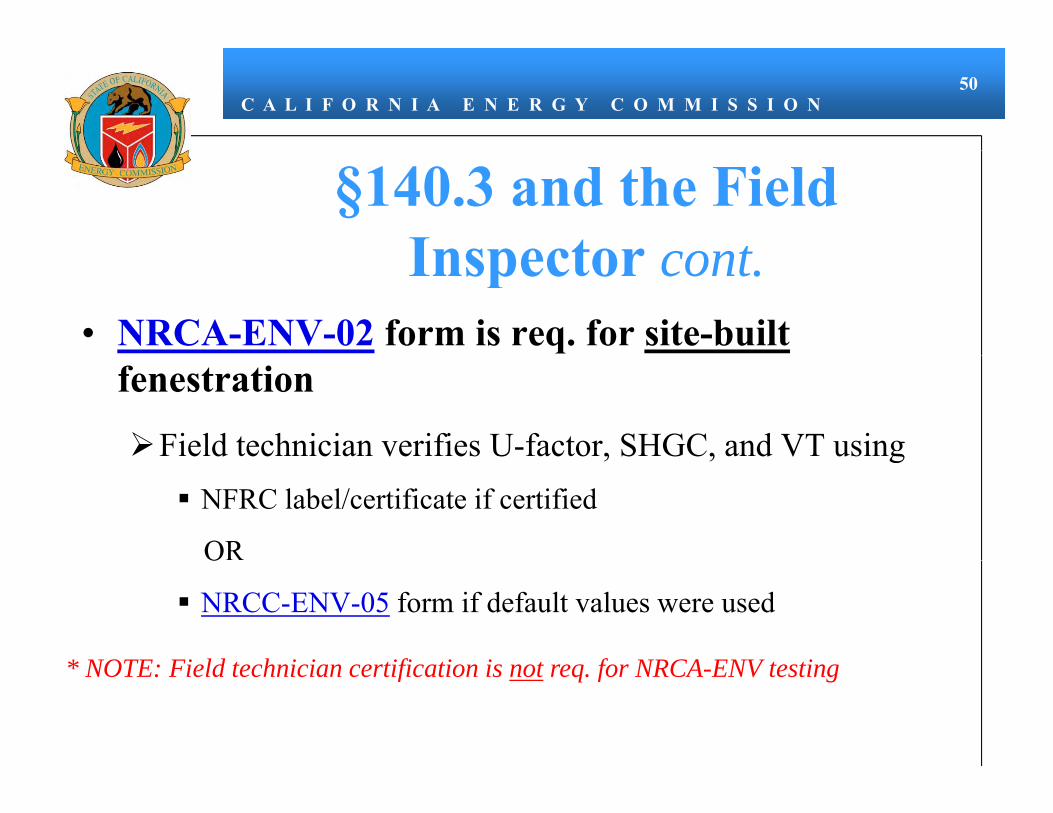
C A L I F O R N I A E N E R G Y C O M M I S S I O N50
§140.3 and the Field Inspector contInspector cont.
• NRCA-ENV-02 form is req. for site-builtfenestration
Field technician verifies U-factor, SHGC, and VT using, , gNFRC label/certificate if certified
ORO
NRCC-ENV-05 form if default values were used
* NOTE Fi ld t h i i tifi ti i t f NRCA ENV t ti* NOTE: Field technician certification is not req. for NRCA-ENV testing

STATE OF CALIFORNIA
FENESTRATION ACCEPTANCE CEC-NRCA-ENV-02-F (Revised 06/13) CALIFORNIA ENERGY COMMISSION
CERTIFICATE OF ACCEPTANCE NRCA‐ENV‐02‐F Fenestration Acceptance (Page 1 of 2)Project Name: Enforcement Agency: Permit Number:
Project Address: City: Zip Code:
CA Building Energy Efficiency Standards ‐ 2013 Nonresidential Compliance June 2013
Note: The Enforcement Agency may optionally verify any Fenestration being installed for authenticity by accessing http://cmast.nfrc.org/Project/CertificateFind.aspx for NFRC CMAST Certificate Labels or NFRC Certificate Labels http://search.nfrc.org/search/searchDefault.aspx See Reference Nonresidential Appendix NA7 for additional information.
A. BUILDING INFORMATION BUILDING TYPE: Low‐rise Nonresidential Low‐rise Schools High Rise Residential Hotel/Motel Guest Room PHASE OF CONSTRUCTION:
New Building Construction Addition Alteration
TYPE OF LABEL CERTIFICATE:
Rated NFRC Component Modeling Approach (CMA) Label Certificate or NFRC Certified Label
NRCC‐ENV‐05‐E ‐ FC‐1 for Nonrated Fenestration Values < 1,000 ft2
NRCC‐ENV‐05‐E ‐ FC‐1 for Nonrated Fenestration Values ≥ 1,000 ft2
TYPE OF INSTALLED FENESTRATION:
Vertical Fenestration
Tubular Daylighting Device (TDD) Skylight Dynamic Glazing Window Film Block Glass
B. STATEMENT OF ACCEPTANCEThis Certificate of Acceptance summarizes the results of the Acceptance test as specified in the Reference Nonresidential Appendix, NA7.4. Additional related references are in Sections §10‐103(a)4, §10‐111, §116(a)5 of the Energy Efficiency Standards.
SUMMARY OF FENESTRATION VERIFICATION AND INSPECTION BY RESPONSIBLE PARTY
Individuals who perform the field testing and verification work, and provide the information required for completion of the Certificate of Acceptance documentation are not required to be licensed professionals. However, the person who signs the Certificate of Acceptance document to certify compliance with the acceptance requirements shall be licensed as specified in Standards Section 10‐103(a)4 and NA7.3.1.
The Responsible Person or Party shall verify the thermal performance (U‐factor, SHGC and VT) of each specified fenestration product being installed matches the fenestration the NFRC Label Certificate, the CEC energy compliance documentation and building plans. Note: A maximum of 4 NFRC Product Listings for each Certificate of Acceptance.
For NFRC Rated Product (If more than 8 fenestration products use additional sheets)
If Product is rated by NFRC then enter the ID # in each column. This includes any of the types of installed fenestration listed above.
1 2 3 4 NFRC Label Certificate ID #
NFRC Label Certificate ID #
NFRC Label Certificate ID # NFRC Label Certificate ID #
5 6 7 8 NFRC Label Certificate ID #
NFRC Label Certificate ID #
NFRC Label Certificate ID # NFRC Label Certificate ID #
For Nonrated Fenestration Attach a copy of the NRCC‐ENV‐05‐E (previously known as FC‐1)
For All Fenestration: Verify and Cross Reference: 1 2 3 4 If receipts or orders are available and it identifies the NFRC ID# then cross reference against the NFRC Label Certificate to match ID#s; or
Delivery Receipt(s) Purchase Order or Detailed Receipt
Delivery Receipt(s) Purchase Order or Detailed Receipt
Delivery Receipt(s) Purchase Order or Detailed Receipt
Delivery Receipt(s) Purchase Order or Detailed Receipt
Cross reference the efficiencies listed on the NFRC Label Certificate of NRCC‐ENV‐05‐E ‐ FC‐1 matches the building plans window schedule of efficiencies.
Cross Reference and Matches Building Plans
Cross Reference and Matches Building Plans
Cross Reference and Matches Building Plans
Cross Reference and Matches Building Plans

STATE OF CALIFORNIA
FENESTRATION CERTIFICATE LABEL CEC-NRCC-ENV-05-E (Revised 06/13) CALIFORNIA ENERGY COMMISSION
CERTIFICATE OF COMPLIANCE NRCC‐ENV‐05‐E Fenestration Certificate Label (Page 1 of 2)Project Name: Date Prepared:
CA Building Energy Efficiency Standards ‐ 2013 Nonresidential Compliance June 2013
This form is only used when an NFRC Label Certificates is not available. A separate (NCRR‐ENV‐05‐E formally FC‐1) Label Certificate Form is required for each different fenestration product or different types of Fenestration.
Method 1: For buildings with less than 1,000 ft2 of site‐built fenestration may optionally use either CEC Default Tables 110.6‐A and 110.6‐B, Method 1, or the Alternative Calculation Nonresidential Reference Appendix NA6, Method 2. Enter the total U‐factorT, SHGCT and VTT (Optional) in the following boxes below.
Method 2: For buildings with greater 1,000 ft2 of site‐built fenestration without NFRC Label Certificate, only one option is available; use CEC Default Tables 110.6‐A and 110.6‐B. Use Method 1 only below and enter the total U‐factorT, SHGCT and VTT in the following boxes below.
A. GENERAL INFORMATION 1 Climate Zone: 2 Total Number of like Fenestration products: 3 Total square footage of like Fenestration:
B. METHOD 1
U‐FACTOR INFORMATION from default, See TABLE 110.6‐A
1 Frame Type: Metal Metal With Thermal Break Nonmetal
2 Product Type: Operable Fixed Greenhouse/Garden Window Doors Skylights
3 Glazing Type: Single Pane Double Pane Glass Block
4 Enter the appropriate value from Table 110.6‐A U‐factorT =
SOLAR HEAT GAIN COEFFICIENT INFORMATION from default, See TABLE 110.6‐B
5 Product Type: Operable Fixed
6 Glazing: Clear Tinted
7 Enter the appropriate value from Table 110.6‐B SHGCT =
VISIBLE TRANSMITTANCE from Reference Nonresidential Appendix NA6
8 Product Type: Casement/Awning
Sliding Fixed Curtainwall/Storefront)/Site‐built Manufactured
Skylights(Non‐curb mounted) Skylights Manufactured (Curb
Mounted)
9 Enter Center‐of‐Glass for VTC value: VTc =
10 Calculate VTT = VTF x VTC (See Equation NA6‐3) VTT =
C. METHOD 2
Alternative Calculation Nonresidential Reference Appendix NA6
NA6 Default Calculation ‐ Enter Center of Glass (COG) value from Manufacturer’s Documentation below: Calculated Values
1 STEP 1: Enter Center‐of‐Glass for U‐factorC or the Uc value:
4 STEP 4: U‐factorT = C1 + (C2 X Uc) U‐factorT =
2 STEP 2: Enter Center‐of‐Glass for SHGCC value:
5 STEP 5: SHGCT = 0.08 + (0.86 x SHGCC) (See Equation NA6‐2)
SHGCT =
3 STEP 3: Enter Center‐of‐Glass for VTC value:
6 STEP 6: VTT = VTF x VTC (See Equation NA6‐3) VTT =
D. ATTACHED MANUFACTURER’S LITERATURE
1 Manufacturer’s literature must match the Product Type, Frame Type, Glazing, Center‐of‐ Glass (COG) U‐factorC, SHGCC and VTC information needed to calculate the Default U‐factorT, SHGCT. and VTT.

C A L I F O R N I A E N E R G Y C O M M I S S I O N51
HVAC2008 – §144
• Loads calcs./sizing
2013 – §140.4• Economizer reqs. updated
• Economizers req. when fan capacity > 2,500 cfm, and
Req. when HVAC capacity > 54,000 Btu/hr
Fan capacity criteria removedHVAC capacity > 75,000 Btu/hr
Fan capacity criteria removed
Economizer trade-offs revised in TABLE 140.4-A
• Air-cooled chillers limited to 100 tons when water plant capacity > 300 tons
Performance reqs. for economizers > 45,000 Btu/hr
• Air-cooled chiller limitationp p y
• Duct leakage testing• Air-cooled chiller limitation
lifted to 300 tons regardless of water plant size

2013 Building Energy Efficiency Standards Page 165
SECTION 140.4 – PRESCRIPTIVE REQUIREMENTS FOR SPACE CONDITIONING SYSTEMS
A. An air economizer capable of modulating outside-air and return-air dampers to supply 100 percent of the design supply air quantity as outside-air; or
B. A water economizer capable of providing 100 percent of the expected system cooling load as calculated in accordance with a method approved by the Commission, at outside air temperatures of 50°F dry-bulb and 45°F wet-bulb and below.
EXCEPTION 1 to Section 140.4(e)1: Where special outside air filtration and treatment, for the reduction and treatment of unusual outdoor contaminants, makes compliance infeasible.
EXCEPTION 2 to Section 140.4(e)1: Where the use of outdoor air for cooling will affect other systems, such as humidification, dehumidification, or supermarket refrigeration systems, so as to increase overall building TDV energy use.
EXCEPTION 3 to Section 140.4(e)1: Systems serving high-rise residential living quarters and hotel/motel guest rooms.
EXCEPTION 4 to Section 140.4(e)1: Where cooling systems have the cooling efficiency that meets or exceeds the cooling efficiency improvement requirements in TABLE 140.4-A.
EXCEPTION 5 to Section 140.4(e)1: Fan systems primarily serving computer room(s). See Section 140.9(a) for computer room economizer requirements.
TABLE 140.4-A ECONOMIZER TRADE-OFF TABLE FOR COOLING SYSTEMS Climate Zone Efficiency Improvement a
a If a unit is rated with an IPLV, IEER or SEER, then to eliminate the required air or water economizer, the applicable minimum cooling efficiency of the HVAC unit must be increased by the percentage shown. If the HVAC unit is only rated with a full load metric, such as EER or COP cooling, then that metric must be increased by the percentage shown.
1 70%
2 65%
3 65%
4 65%
5 70%
6 30%
7 30%
8 30%
9 30%
10 30%
11 30%
12 30%
13 30%
14 30%
15 30%
16 70%
2. If an economizer is required by Section 140.4(e)1 it shall be:
A. Designed and equipped with controls so that economizer operation does not increase the building heating energy use during normal operation; and
EXCEPTION to Section 140.4(e)2A: Systems that provide 75 percent of the annual energy used for mechanical heating from site-recovered energy or a site-solar energy source.
B. Capable of providing partial cooling even when additional mechanical cooling is required to meet the remainder of the cooling load.
3. If an economizer is required by Section 140.4(e)1, and an air economizer is used to meet the requirement, then it shall be a type listed in, and shall have high limit shutoff controls complying with TABLE 140.4-B,

2013 Building Energy Efficiency Standards Page 166
SECTION 140.4 – PRESCRIPTIVE REQUIREMENTS FOR SPACE CONDITIONING SYSTEMS
TABLE 140.4-B AIR ECONOMIZER HIGH LIMIT SHUT OFF CONTROL REQUIREMENTS
Device Typea Climate Zones Required High Limit (Economizer Off When):
Equationb Description
Fixed Dry Bulb
1, 3, 5, 11-16 TOA > 75°F Outdoor air temperature exceeds 75°F
2, 4, 10 TOA > 73°F Outdoor air temperature exceeds 73°F
6, 8, 9 TOA > 71°F Outdoor air temperature exceeds 71°F
7 TOA > 69°F Outdoor air temperature exceeds 69°F
Differential Dry Bulb
1, 3, 5, 11-16 TOA > TRA°F Outdoor air temperature exceeds return air temperature
2, 4, 10 TOA > TRA-2°F Outdoor air temperature exceeds return air temperature minus 2°F
6, 8, 9 TOA > TRA-4°F Outdoor air temperature exceeds return air temperature minus 4°F
7 TOA > TRA-6°F Outdoor air temperature exceeds return air temperature minus 6°F
Fixed Enthalpyc + Fixed Drybulb All hOA > 28 Btu/lbc or TOA > 75°F
Outdoor air enthalpy exceeds 28 Btu/lb of dry airc or Outdoor air temperature exceeds 75°F
a Only the high limit control devices listed are allowed to be used and at the setpoints listed. Others such as Dew Point, Fixed Enthalpy, Electronic Enthalpy, and Differential Enthalpy Controls, may not be used in any Climate Zone for compliance with Section 140.4(e)1 unless approval for use is provided by the Energy Commission Executive Director. b Devices with selectable (rather than adjustable) setpoints shall be capable of being set to within 2°F and 2 Btu/lb of the setpoint listed. c At altitudes substantially different than sea level, the Fixed Enthalpy limit value shall be set to the enthalpy value at 75°F and 50% relative humidity. As an example, at approximately 6,000 foot elevation, the fixed enthalpy limit is approximately 30.7 Btu/lb.
4. If an economizer is required by Section 140.4(e)1, and an air economizer is used to meet the requirement, then the air economizer, and all return air dampers on any individual cooling fan system that has a total mechanical cooling capacity over 45,000 Btu/hr shall have the following features:
A. Warranty. 5-year Manufacturer warranty of economizer assembly.
B. Damper reliability testing. Suppliers of economizers shall certify that the economizer assembly, including but not limited to outdoor air damper, return air damper, drive linkage, and actuator, have been tested and are able to open and close against the rated airflow and pressure of the system after 60,000 damper opening and closing cycles.
C. Damper leakage. Economizer and return dampers shall be certified in accordance with AMCA Publication 500 to have a maximum leakage rate of 10 cfm/sf at 1.0 in. w.g.
D. Adjustable setpoint. If the high-limit control is fixed dry-bulb or fixed enthalpy + fixed dry-bulb then the control shall have an adjustable setpoint.
E. Sensor accuracy. Outdoor air, return air, mixed air, and supply air sensors shall be calibrated within the following accuracies.
i. Drybulb and wetbulb temperatures accurate to ±2°F over the range of 40°F to 80°F.
ii. Enthalpy accurate to ±3 Btu/lb over the range of 20 Btu/lb to 36 Btu/lb.
iii. Relative humidity (RH) accurate to ±5 percent over the range of 20percent to 80 percent RH.
F. Sensor calibration data. Data used for control of the economizer shall be plotted on a sensor performance curve.

2013 Building Energy Efficiency Standards Page 167
SECTION 140.4 – PRESCRIPTIVE REQUIREMENTS FOR SPACE CONDITIONING SYSTEMS
G. Sensor high limit control. Sensors used for the high limit control shall be located to prevent false readings, including but not limited to being properly shielded from direct sunlight.
H. Relief air system. Relief air systems shall be capable of providing 100 percent outside air without over-pressurizing the building.
5. Systems that include an air economizer to meet Section 140.4(e)1 shall include the following:
A. Unit controls shall have mechanical capacity controls interlocked with economizer controls such that the economizer is at 100 percent open position when mechanical cooling is on and does not begin to close until the leaving air temperature is less than 45oF.
B. Direct Expansion (DX) units that control the capacity of the mechanical cooling directly based on occupied space temperature shall have a minimum of 2 stages of mechanical cooling capacity, per the following effective dates:
i. ≥ 75,000 Btu/hr – Effective 1/1/2014
ii. ≥ 65,000 Btu/hr – Effective 1/1/2016
C. Effective 1/1/2014, DX units not within the scope of Section 140.4(e)5,B, such as those that control space temperature by modulating the airflow to the space, shall (i) comply with the requirements in TABLE 140.4-C, and (ii) shall have controls that do not false load the mechanical cooling system by limiting or disabling the economizer or by any other means, such as hot gas bypass, except at the lowest stage of mechanical cooling capacity.
TABLE 140.4-C DIRECT EXPANSION (DX) UNIT REQUIREMENTS FOR COOLING STAGES AND COMPRESSOR DISPLACEMENT
Cooling Capacity Minimum Number of Mechanical Cooling Stages
Minimum Compressor Displacement
≥ 65,000 Btu/h and
< 240,000 Btu/h 3 stages
≤ 35% full load
≥ 240,000 Btu/h 4 stages ≤ 25% full load
(f) Supply Air Temperature Reset Controls. Space-conditioning systems supplying heated or cooled air to multiple zones shall include controls that automatically reset supply-air temperatures. Air distribution systems serving zones that are likely to have constant loads, such as interior zones, shall be designed for the air flows resulting from the fully reset supply air temperature. Supply air temperature reset controls shall be:
1. In response to representative building loads or to outdoor air temperature; and
2. At least 25 percent of the difference between the design supply-air temperature and the design room air temperature.
EXCEPTION 1 to Section 140.4(f): Systems that meet the requirements of Section 140.4(d), without using Exception 1 or 2 to that section.
EXCEPTION 2 to Section 140.4(f): Where supply-air temperature reset would increase overall building energy use.
EXCEPTION 3 to Section 140.4(f): Systems supplying zones in which specific humidity levels are required to satisfy exempt process loads. Computer Rooms or other spaces with only IT equipment may not use this exception.
(g) Electric Resistance Heating. Electric resistance heating systems shall not be used for space heating.
EXCEPTION 1 to Section 140.4(g): Where an electric-resistance heating system supplements a heating system in which at least 60 percent of the annual energy requirement is supplied by site-solar or recovered energy.

C A L I F O R N I A E N E R G Y C O M M I S S I O N52
§140.4 and the Plans ExaminerExaminer
• Verify on NRCC-MCH-02Specifications for economizers when req. (Page 1)
Specifications for air cooledSpecifications for air-cooled chillers when applicable (Page 2)
Form should cite building plans reference
Mechanical schedule, note block, etc.
• Forms must be registered starting 1/1/15

STATE OF CALIFORNIA
HVAC SYSTEM REQUIREMENTS CEC-NRCC-MCH-02-E (Revised 06/13) CALIFORNIA ENERGY COMMISSION
CERTIFICATE OF COMPLIANCE NRCC‐MCH‐02‐E HVAC Dry System Requirements (Page 1 of 3)Project Name: 2013 CALBO Training Sample Date Prepared: 01/01/14
CA Building Energy Efficiency Standards ‐ 2013 Nonresidential Compliance June 2013
Equipment Tags and System Description1 HVAC-1 MANDATORY MEASURES T‐24 Sections Reference to the Requirements in the Contract Documents2
Heating Equipment Efficiency3 110.1 or 110.2(a) 100,000 btu/hr Cooling Equipment Efficiency3 110.1 or 110.2(a) 5 ton HVAC or Heat Pump Thermostats 110.2(b), 110.2(c) M.1 (note block) Furnace Standby Loss Control 110.2(d) M.1 (note block) Low leakage AHUs 110.2(f) M.1 (note block) Ventilation4 120.1(b) M.2 (schedule) Demand Control Ventilation5 120.1(c)4 N/A Occupant Sensor Ventilation Control6 120.1(c)5, 120.2(e)3 N/A Shutoff and Reset Controls7 120.2(e) M.1 (note block) Outdoor Air and Exhaust Damper Control 120.2(f) M.1 (note block) Isolation Zones 120.2(g) M.1 (note block) Automatic Demand Shed Controls 120.2(h) N/A Economizer FDD 120.2(i) N/A Duct Insulation 120.4 R-8 PRESCRIPTIVE MEASURES
Equipment is sized in conformance with 140.4 (a & b)
140.4(a & b)Y/N Y/N Y/N
Supply Fan Pressure Control 140.4(c) N Simultaneous Heat/Cool8 140.4(d) N Economizer 140.4(e) Y (M.3 schedule) Heat and Cool Air Supply Reset 140.4(f) N Electric Resistance Heating9 140.4(g) N Duct Leakage Sealing and Testing.10 140.4(l) Y (HERS) Notes: 1. Provide equipment tags (e.g. AHU 1 to 10) and system description (e.g. Single Duct VAV reheat) as appropriate. Multiple units
with common requirements can be grouped together. 2. Provide references to plans (i.e. Drawing Sheet Numbers) and/or specifications (including Section name/number and relevant
paragraphs) where each requirement is specified. Enter "N/A" if the requirement is not applicable to this system. 3. The referenced plans and specifications must include all of the following information: equipment tag, equipment nominal
capacity, Title 24 minimum efficiency requirements, and actual rated equipment efficiencies. Where multiple efficiency requirements are applicable (e.g. full‐ and part‐load) include all. Where appliance standards apply (110.1), identify where equipment is required to be listed per Title 20 1601 et seq.
4. Identify where the ventilation requirements are documented for each central HVAC system. Include references to both central unit schedules and sequences of operation. If one or more space is naturally ventilated identify where this is documented in the plans and specifications. Multiple zone central air systems must also provide a MCH‐03‐E form.
5. If one or more space has demand controlled ventilation identify where it is specified including the sensor specifications and the sequence of operation.
6. If one or more space has occupant sensor ventilation control identify where it is specified including the sensor specifications and the sequence of operation
7. If the system is DDC identify the sequences for the system start/stop, optimal start, setback (if required) and setup (if required). For all systems identify the specification for the thermostats and time clocks (if applicable).
8. Identify where the heating, cooling and deadband airflows are scheduled for this system. Include a reference to the specification of the zone controls. Provide a MCH‐03‐E form.
9. Enter N/A if there is no electric heating. If the system has electric heating indicate which exception to 140.4(g) applies. 10. If duct leakage sealing and testing is required, a MCH‐04‐A form must be submitted.

STATE OF CALIFORNIA
HVAC WET SYSTEM REQUIREMENTS CEC-NRCC-MCH-02-E (Revised 06/13) CALIFORNIA ENERGY COMMISSION
CERTIFICATE OF COMPLIANCE NRCC‐MCH‐02‐E HVAC Wet System Requirements (Page 2 of 3)Project Name: Date Prepared:
CA Building Energy Efficiency Standards ‐ 2013 Nonresidential Compliance June 2013
Equipment Tags and System Description1 Chiller 1 MANDATORY MEASURES T‐24 Sections Reference to the Requirements in the Contract Documents2
Heating Hot Water Equipment Efficiency3 110.1 Cooling Chilled and Condenser Water Equipment Efficiency3
110.1, 140.4(i) M.1 (note block)
Open and Closed Circuit Cooling Towers conductivity or flow‐based controls
110.2(e) 1 M.1 (note block)
Open and Closed Circuit Cooling Towers Maximum Achievable Cycles of Concentration (LSI)6
110.2(e) 2M.1 (note block)
Open and Closed Circuit Cooling Towers Flow Meter with analog output
110.2(e) 3 M.1 (note block)
Open and Closed Circuit Cooling Towers Overflow Alarm
110.2(e) 4 M.1 (note block)
Open and Closed Circuit Cooling Towers Efficient Drift Eliminators
110.2(e) 5 M.1 (note block)
Pipe Insulation 120.3 2.0 in. PRESCRIPTIVE MEASURES
Cooling Tower Fan Controls 140.4(h)2, 140.4(h)5 Y/N Y/N Y/NCooling Tower Flow Controls 140.4(h)3 Y (note block) Centrifugal Fan Cooling Towers4 140.4(h)4 Y (note block) Air‐Cooled Chiller Limitation5 140.4(j) Y - 250 tons Variable Flow System Design 140.4(k) N Chiller and Boiler Isolation 140.4(k) Y (note block) CHW and HHW Reset Controls 140.4(k) N WLHP Isolation Valves 140.4(k) N VSD on CHW, CW & WLHP Pumps >5HP 140.4(k) N DP Sensor Location 140.4(k) N Notes: 1. Provide equipment tags (e.g. CH 1 to 3) or system description (e.g. CHW loop) as appropriate. Multiple units with common
requirements can be grouped together. 2. Provide references to plans (i.e. Drawing Sheet Numbers) and/or specifications (including Section name/number and relevant
paragraphs) where each requirement is specified. Enter "N/A" if the requirement is not applicable to this system. 3. The referenced plans and specifications must include all of the following information: equipment tag, equipment nominal
capacity, Title 24 minimum efficiency requirements, and actual rated equipment efficiencies. Where multiple efficiency requirements are applicable (e.g. full‐ and part‐load) include all. For chillers operating at non‐standard efficiencies provide the Kadj values. For chillers also note whether the efficiencies are Path A or Path B.
4. Identify if cooling towers have propeller fans. If towers use centrifugal fans document which exception is used. 5. If air‐cooled chillers are used, document which exceptions have been used to comply with 140.4(j) and the total installed design
capacity of the air‐cooled chillers in the chilled water plant. 6. Identify the existence of a completed MCH‐06‐E \when open or closed circuit cooling towers are specified to be installed,
otherwise enter “N/A”.

C A L I F O R N I A E N E R G Y C O M M I S S I O N53
§140.4 and the Plans Examiner contExaminer cont.
• Other Prescriptive NRCC-MCH forms:NRCC-MCH-01
Identifies req. NRCC and NRCA forms
NRCC-MCH-03Ventilation and reheat
NRCC-MCH-05 Packaged, single zone units
NRCC-MCH-06Maximum cycles worksheet

C A L I F O R N I A E N E R G Y C O M M I S S I O N54
§140.4 and the Field InspectorInspector
• At Final verifyEconomizer installed when req.
Economizer is certified to CEC when > 45,000 Btu/hrwhen 45,000 Btu/hr
NRCA-MCH-05 form
Must be signed by CMATT hwhen req.
Must be registered starting 1/1/15
Air-cooled chiller capacity does not exceed 300 tons

STATE OF CALIFORNIA
AIR ECONOMIZER CONTROLS ACCEPTANCE CEC-NRCA-MCH-05-A (Revised 06/13) CALIFORNIA ENERGY COMMISSION
CERTIFICATE OF ACCEPTANCE NRCA‐MCH‐05‐A Air Economizer Controls Acceptance (Page 1 of 3)Project Name: 2013 CALBO Training Sample Enforcement Agency: Local Jurisdiction Permit Number: 010113
Project Address: 2013 CALBO Drive City: Sacramento Zip Code: 95814
CA Building Energy Efficiency Standards ‐ 2013 Nonresidential Compliance June 2013
Note: Submit one Certificate of Acceptance for each system that must demonstrate compliance.
Enforcement Agency Use: Checked by/Date
A. Construction Inspection
1. Supporting documentation needed to perform test includes:
a. 2013 Building Energy Efficiency Standards Nonresidential Compliance Manual (NA7.5.4 Air Economizer Controls Acceptance At‐A‐Glance).
b. 2013 Building Energy Efficiency Standards.
2. Instrumentation to perform test includes:
a. Hand‐held temperature probe
Calibration Date: 1/1/14 (must be within last year)
b. Meter capable of measuring enthalpy
Calibration Date: 1/1/14 (must be within last year)
c. 1.2 k Ohm Resistor (for standalone package systems, i.e. non‐DDC controls)
3. Installation: (all of the following boxes should be checked) ⌧
Economizer lockout setpoint complies with Table 140.4‐B found in the 2013 Building Energy Efficiency Standards Section 140.4(e)3.
⌧ Economizer reliability features are present per 2013 Building Energy Efficiency Standards Section 140.4(e)4:
⌧ A. 5‐year manufacturer warranty of economizer assembly
⌧ B. Provide a product specification sheet proving capability of at least 60,000 actuations
⌧ C. Provide a product specification sheet proving economizer damper sections are certified by AMCA 511 for a maximum damper leakage rate of 10 cfm/sf at 1.0 in. w.g. (Class 1A, 1, and 2 are acceptable)
⌧ D. If the high limit setpoint is fixed dry‐bulb or fixed enthalpy + fixed dry‐bulb then the control shall have an adjustable setpoint
⌧ E. Outdoor air, return air, mixed air, and supply air sensors shall be calibrated as follows:
i. Drybulb and wetbulb temperatures accurate to ±2°F over the range of 40°F to 80°F
ii. Enthalpy accurate to ±3 Btu/lb over the range of 20 Btu/lb to 36 Btu/lb
iii. Relative humidity (RH) accurate to ±5% over the range of 20% to 80% RH
⌧F. Check that the sensor performance curve(s) is provided by the factory and sensor output values measured during sensor calibration are plotted on the performance curve(s)
⌧ G. Sensors used for high limit control shall be located to prevent false readings, including but not limited to being properly shielded from direct sunlight.
⌧ For DX package units 65,000 Btu/hr or less, verify that a two‐stage thermostat is used, and the system is wired so the economizer is
the first stage of cooling and the compressor is the second stage
⌧ Unitary systems with an economizer have control systems, including two‐stage or electronic thermostats, that cycle compressors off
when economizers can provide partial cooling
⌧ System has return fan speed control, relief dampers, or dedicated relief fans to prevent building over pressurization in full
economizer mode.
⌧ For systems with DDC controls, sensor used for economizer lockout has been factory or field calibrated.
⌧ For systems with non‐DDC controls, manufacturer's startup and testing procedures have been applied.

STATE OF CALIFORNIA
AIR ECONOMIZER CONTROLS ACCEPTANCE CEC-NRCA-MCH-05-A (Revised 06/13) CALIFORNIA ENERGY COMMISSION
CERTIFICATE OF ACCEPTANCE NRCA‐MCH‐05‐A Air Economizer Controls Acceptance (Page 2 of 3)Project Name: 2013 CALBO Training Sample Enforcement Agency: Local Jurisdiction Permit Number: 010113
Project Address: 2013 CALBO Drive City: Sacramento Zip Code: 95814
CA Building Energy Efficiency Standards ‐ 2013 Nonresidential Compliance June 2013
B. Functional Testing Results
Step 1: Disable demand control ventilation systems (if applicable)
Step 2: Enable the economizer and simulate a cooling demand large enough to drive the economizer fully open. Verify the following:
a. Economizer damper modulates 100% open. Y / N
b. Return air damper modulates 100% closed. Y / N
c. For systems that meet the criteria of 2013 Building Energy Efficiency Standards Section 140.4(e)1, verify that the economizer remains 100% open with the use of mechanical cooling. This occurs when the cooling demand can no longer be met by the economizer alone.
Y / N
d. All applicable fans and dampers operate as intended to maintain building pressure. Y / N
e. The unit heating is disabled (if applicable). Y / N / NA
Step 3: Disable the economizer and simulate a cooling demand. Verify the following:
a. Economizer damper closes to its minimum position. Y / N
b. All applicable fans and dampers operate as intended to maintain building pressure. Y / N
c. The unit heating is disabled (if applicable). Y / N / NA
Step 4: If the unit is equipped with heating, simulate a heating demand and enable the economizer. Verify the following:
a. Economizer damper closes to its minimum position. Y / N / NA
b. Return air damper opens. Y / N / NA
Step 5: Turn off the unit and verify the following:
a. Economizer damper closes completely. Y / N
Step 6: System returned to initial operating conditions Y / N
C. Testing Results PASS / FAIL Step 2: Simulate cooling load and enable the economizer (all answers are Y). Pass
Step 3: Simulate cooling load and disable the economizer (all answers are Y). Pass
Step 4: Simulate heating demand and enable the economizer (all answers are Y). Pass
Step 5: Turn off the unit (all answers are Y). Pass
D. Evaluation : ⌧ PASS: All Construction Inspection responses are complete and all Testing Results responses are "Pass"
Notes:

C A L I F O R N I A E N E R G Y C O M M I S S I O N55
§140.4 and the Plans Examiner contExaminer cont.
• Required NRCA-MCH forms/testing must be verified b f fi l it i i dbefore final occupancy permit is issued
Refer to NRCC-MCH-01 form
• Frequently req. test include:Outdoor air ventilation (NRCA-MCH-02)
Single zone unitary A/C and HP controls (NRCA-MCH-03)
Duct leakage (NRCA-MCH-04) – does not req. CMATTNRCV-MCH-04 req. (HERS rater test)
DCV (NRCA-MCH-06)

STATE OF CALIFORNIA
MECHANICAL SYSTEMS CEC-NRCC-MCH-01-E (Revised 06/13) CALIFORNIA ENERGY COMMISSION
CERTIFICATE OF COMPLIANCE NRCC‐MCH‐01‐E Mechanical Systems (Page 1 of 4) Project Name: 2013 CALBO Training Sample Date Prepared: 01/01/14
CA Building Energy Efficiency Standards ‐ 2013 Nonresidential Compliance June 2013
MECHANICAL COMPLIANCE FORMS & WORKSHEETS (check box if worksheet is included)
For detailed instructions on the use of this and all Energy Efficiency Standards compliance forms, refer to the 2013 Nonresidential Manual Note: The Enforcement Agency may require all forms to be incorporated onto the building plans.
YES NO Form/Worksheet # Title⌧ NRCC‐MCH‐01E (Part 1 of 3) Certificate of Compliance, Declaration. Required on plans for all submittals.⌧ NRCC‐MCH‐01E (Part 2 of 3) Certificate of Compliance, Required Acceptance Tests (MCH‐02A to 11A). Required on plans for all submittals.⌧ NRCC‐MCH‐01E (Part 3 of 3) Certificate of Compliance, Required Acceptance Tests (MCH‐12A to 18A). Required on plans where applicable.⌧ NRCC‐MCH‐02E (Part 1 of 2) Mechanical Dry Equipment Summary is required for all submittals with Central Air Systems. It is optional on plans. ⌧ NRCC‐MCH‐02E (Part 2 of 2) Mechanical Wet Equipment Summary is required for all submittals with chilled water, hot water or condenser water
systems. It is optional on plans. ⌧ NRCC‐MCH‐03E Mechanical Ventilation and Reheat is required for all submittals with multiple zone heating and cooling systems. It is
optional on plans.
MECHANICAL HVAC ACCEPTANCE FORMS (check box for required forms) Designer: This form is to be used by the designer and attached to the plans. Listed below are all the acceptance tests for HVAC systems. The designer is required to check the applicable boxes for all acceptance tests that apply and list all equipment that requires an acceptance test. All equipment of the same type that requires a test, list the equipment description and the number of systems. Installing Contractor: The contractor who installed the equipment is responsible to either conduct the acceptance test them self or have a qualified entity run the test for them. If more than one person has responsibility for the acceptance testing, each person shall sign and submit the Certificate of Acceptance applicable to the portion of the construction or installation for which they are responsible. Enforcement Agency: Plancheck – The NRCC‐MCH‐01‐E form is not considered a completed form and is not to be accepted by the building department unless the correct boxes are checked. Inspector ‐ Before occupancy permit is granted all newly installed process systems must be tested to ensure proper operations.
Test Description MCH‐02A MCH‐03A MCH‐04A MCH‐05A MCH‐06A MCH‐07A MCH‐08A MCH‐09A MCH‐10A MCH‐11A Equipment Requiring Testing or Verification
# of units
Outdoor Ventilation
Single Zone Unitary
Air Distribution
Ducts
Economizer Controls
Demand Control
Ventilation (DCV)
Supply Fan VAV
Valve Leakage Test
Supply Water Temp. Reset
Hydronic System
Variable Flow Control
Automatic Demand Shed
Control
A/C 5 ton unit 2 ⌧ ⌧ ⌧
Economizer 1 ⌧

C A L I F O R N I A E N E R G Y C O M M I S S I O N56
Lighting2008 – §146
• Allowed lighting power 2
2013 – §140.6• Allowed watts/ft2
density (watts/ft2)Complete building methodArea category method
TABLES 140.6-B through D
No major changes for complete building and areaArea category method
Tailored methodTABLES 146-E through G
complete building and area category method values
Tailored method values h d d d i d b
• Power adjustment factor (PAF)
R d d tt /ft2
changed and determined by general illumination level (Lux)
Reduces proposed watts/ft2
with lighting controlsTABLE 146-C
• PAFs updatedTABLE 140.6-A
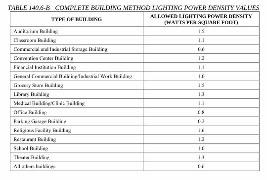
2013 Building Energy Efficiency Standards Page 183
SECTION 140.6 – PRESCRIPTIVE REQUIREMENTS FOR INDOOR LIGHTING
TABLE 140.6-B COMPLETE BUILDING METHOD LIGHTING POWER DENSITY VALUES
TYPE OF BUILDING ALLOWED LIGHTING POWER DENSITY (WATTS PER SQUARE FOOT)
Auditorium Building 1.5
Classroom Building 1.1
Commercial and Industrial Storage Building 0.6
Convention Center Building 1.2
Financial Institution Building 1.1
General Commercial Building/Industrial Work Building 1.0
Grocery Store Building 1.5
Library Building 1.3
Medical Building/Clinic Building 1.1
Office Building 0.8
Parking Garage Building 0.2
Religious Facility Building 1.6
Restaurant Building 1.2
School Building 1.0
Theater Building 1.3
All others buildings 0.6
TABLE 140.6-C AREA CATEGORY METHOD - LIGHTING POWER DENSITY VALUES (WATTS/FT²)
PRIMARY FUNCTION AREA ALLOWED LIGHTING
POWER (W/ft²) PRIMARY FUNCTION AREA ALLOWED LIGHTING
POWER (W/ft²)
Auditorium Area 1.5 3 Library Area Reading areas 1.2 3
Auto Repair Area 0.9 2 Stack areas 1.5 3
Beauty Salon Area 1.7 Lobby Area Hotel lobby 1.1 3
Civic Meeting Place Area 1.3 3 Main entry lobby 1.5 3
Classroom, Lecture, Training, Vocational Areas 1.2 5 Locker/Dressing Room 0.8
Commercial and Industrial Storage Areas (conditioned and unconditioned) 0.6 Lounge Area 1.1 3
Commercial and Industrial Storage Areas (refrigerated) 0.7 Malls and Atria 1.2 3
Convention, Conference, Multipurpose and Meeting Center Areas 1.4 3 Medical and Clinical Care Area 1.2
Corridor, Restroom, Stair, and Support Areas 0.6 Office Area > 250 square feet 0.75
Dining Area 1.1 3 ≤ 250 square feet 1.0
Electrical, Mechanical, Telephone Rooms 0.7 2 Parking Garage Area Parking Area 0.14
Exercise Center, Gymnasium Areas 1.0 Dedicated Ramps 0.3
Exhibit, Museum Areas 2.0 Daylight Adaptation Zones 9 0.6
Financial Transaction Area 1.2 3 Religious Worship Area 1.5 3
General Commercial and Industrial Work Areas
Low bay 0.9 2 Retail Merchandise Sales, Wholesale Showroom Areas 1.2 6 and 7
High bay 1.0 2
Precision 1.2 4 Theater Area Motion picture 0.9 3

TABLE 140.6-C AREA CATEGORY METHOD - LIGHTING POWER DENSITY VALUES (WATTS/FT²)
PRIMARY FUNCTION AREA
ALLOWED LIGHTING
POWER (W/ft²)
PRIMARY FUNCTION AREA ALLOWED LIGHTING POWER (W/ft²)
Auditorium Area 1.5 3 Library Area Reading areas 1.2 3
Auto Repair Area 0.9 2 Stack areas 1.5 3
Beauty Salon Area 1.7 Lobby Area Hotel lobby 1.1 3
Civic Meeting Place Area 1.3 3 Main entry lobby 1.5 3
Classroom, Lecture, Training, Vocational Areas 1.2 5 Locker/Dressing Room 0.8
Commercial and Industrial Storage Areas (conditioned and unconditioned) 0.6 Lounge Area 1.1 3
Commercial and Industrial Storage Areas (refrigerated) 0.7 Malls and Atria 1.2 3
Convention, Conference, Multipurpose and Meeting Center Areas 1.4 3 Medical and Clinical Care Area 1.2
Corridor, Restroom, Stair, and Support Areas 0.6 Office Area > 250 square feet 0.75
Dining Area 1.1 3 ≤ 250 square feet 1.0
Electrical, Mechanical, Telephone Rooms 0.7 2 Parking Garage
Area Parking Area 0.14
Exercise Center, Gymnasium Areas 1.0 Dedicated Ramps 0.3
Exhibit, Museum Areas 2.0 Daylight Adaptation Zones 9 0.6
Financial Transaction Area 1.2 3 Religious Worship Area 1.5 3
General Commercial and Industrial Work Areas
Low bay 0.9 2 Retail Merchandise Sales, Wholesale Showroom Areas 1.2 6 and 7
High bay 1.0 2
Precision 1.2 4 Theater Area Motion picture 0.9 3
Grocery Sales Area 1.2 6 and 7 Performance 1.4 3
Hotel Function Area 1.5 3 Transportation Function Area 1.2
Kitchen, Food Preparation Areas 1.6 Videoconferencing Studio 1.2 8
Laboratory Area, Scientific 1.4 1 Waiting Area 1.1 3
Laundry Area 0.9 All other areas 0.6
Footnotes for this table are listed below.
FOOTNOTES FOR TABLE 140.6-C: See Section 140.6(c)2 for an explanation of additional lighting power available for specialized task work, ornamental, precision, accent, display, decorative, and white boards and chalk boards, in accordance with the footnotes in this table. The smallest of the added lighting power listed in each footnote below, or the actual design wattage, may be added to the allowed lighting power only when using the Area Category Method of compliance.
Footnote number
Type of lighting system allowed Maximum allowed added lighting power. (W/ft2 of task area unless otherwise noted)
1 Specialized task work 0.2 W/ft2
2 Specialized task work 0.5 W/ft2
3 Ornamental lighting as defined in Section 100.1 and in accordance with Section 140.6.(c)2.
0.5 W/ft2
4 Precision commercial and industrial work 1.0 W/ft2
5 Per linear foot of white board or chalk board. 5.5 W per linear foot
6 Accent, display and feature lighting - luminaires shall be adjustable or directional
0.3 W/ft2
7 Decorative lighting - primary function shall be decorative and shall be in addition to general illumination.
0.2 W/ft2
8 Additional Videoconferencing Studio lighting complying with all of the requirements in Section 140.6(c)2Gvii.
1.5 W/ft2
9 Daylight Adaptation Zones shall be no longer than 66 feet from the entrance to the parking garage

2013 Building Energy Efficiency Standards Page 185
SECTION 140.6 – PRESCRIPTIVE REQUIREMENTS FOR INDOOR LIGHTING
TABLE 140.6-D TAILORED METHOD LIGHTING POWER ALLOWANCES 1 2 3 4 5
Primary Function Area General
Illumination Level (Lux)
Wall Display Power (W/ft)
Allowed Combined Floor Display Power
and Task Lighting Power
(W/ft²)
Allowed Ornamental/ Special Effect Lighting
Auditorium Area 300 2.25 0.3 0.5
Civic Meeting Place 300 3.15 0.2 0.5
Convention, Conference, Multipurpose, and Meeting Center Areas 300 2.50 0.4 0.5
Dining Areas 200 1.50 0.6 0.5
Exhibit, Museum Areas 150 15.0 1.2 0.5
Financial Transaction Area 300 3.15 0.2 0.5
Grocery Store Area 500 8.00 0.9 0.5
Hotel Function Area 400 2.25 0.2 0.5
Lobby Area:
Hotel lobby 200 3.15 0.2 0.5
Main entry lobby 200 0 0.2 0
Lounge Area 200 7.00 0 0.5
Malls and Atria 300 3.50 0.5 0.5
Religious Worship Area 300 1.50 0.5 0.5
Retail Merchandise Sales, and Showroom Areas 400 14.00 1.0 0.5
Theater Area:
Motion picture 200 3.00 0 0.5
Performance 200 6.00 0 0.5
Transportation Function Area 300 3.15 0.3 0.5
Waiting Area 300 3.15 0.2 0.5
TABLE 140.6-E ADJUSTMENTS FOR MOUNTING HEIGHT ABOVE FLOOR Height in feet above finished floor and bottom of
luminaire(s) Floor Display or Wall Display – Multiply by
< 12' 1.00
12' to 16' 1.15
> 16’ 1.30
TABLE 140.6-F ROOM CAVITY RATIO (RCR) EQUATIONS Determine the Room Cavity Ratio for TABLE 140.6-G using one of the following equations.
Room cavity ratio for rectangular rooms
WL)WL(H5RCR
×+××
=
Room cavity ratio for irregular-shaped rooms
APHRCR ××
=5.2
Where: L =Length of room; W = Width of room; H =Vertical distance from the work plane to the centerline of the lighting fixture; P = Perimeter of room, and A = Area of room
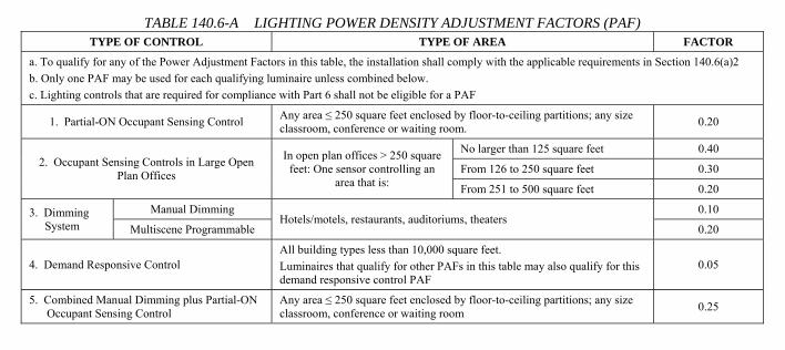
2013 Building Energy Efficiency Standards Page 182
SECTION 140.6 – PRESCRIPTIVE REQUIREMENTS FOR INDOOR LIGHTING
iii. To qualify for additional allowed power for very valuable display case lighting, a case shall contain jewelry, coins, fine china, fine crystal, precious stones, silver, small art objects and artifacts, and/or valuable collections the display of which involves customer inspection of very fine detail from outside of a locked case.
iv. Qualifying lighting includes internal display case lighting or external lighting employing highly directional luminaires specifically designed to illuminate the case or inspection area without spill light, and shall not be fluorescent lighting unless installed inside of a display case.
v. If there is qualifying very valuable display case lighting, in accordance with Section 140.6(c)3Liii, the smallest of the following separate lighting power for display cases presenting very valuable display items is permitted:
a. The product of the area of the primary function and 0.8 watt per square foot; or
b. The product of the area of the display case and 12 watts per square foot; or
c. The actual power of lighting for very valuable displays.
(d) Automatic Daylighting Controls in Secondary Daylit Zones. All luminaires providing general lighting that is in, or partially in a Secondary Sidelit Daylit Zone as defined in Section 130.1(d)1C, and that is not in a Primary Sidelit Daylit Zone shall:
1. Be controlled independently from all other luminaires by automatic daylighting controls that meet the applicable requirements of Section 110.9; and
2. Be controlled in accordance with the applicable requirements in Section 130.1(d)2; and
3. All Secondary Sidelit Daylit Zones shall be shown on the plans submitted to the enforcing agency.
EXCEPTION 1 to Section 140.6(d): Luminaires in Secondary Sidelit Daylit Zone(s) in areas where the total wattage of general lighting is less than 120 Watts.
EXCEPTION 2 to Section 140.6(d): Luminaires in parking garages complying with Section 130.1(d)3.
TABLE 140.6-A LIGHTING POWER DENSITY ADJUSTMENT FACTORS (PAF) TYPE OF CONTROL TYPE OF AREA FACTOR
a. To qualify for any of the Power Adjustment Factors in this table, the installation shall comply with the applicable requirements in Section 140.6(a)2 b. Only one PAF may be used for each qualifying luminaire unless combined below. c. Lighting controls that are required for compliance with Part 6 shall not be eligible for a PAF
1. Partial-ON Occupant Sensing Control Any area ≤ 250 square feet enclosed by floor-to-ceiling partitions; any size classroom, conference or waiting room. 0.20
2. Occupant Sensing Controls in Large Open Plan Offices
In open plan offices > 250 square feet: One sensor controlling an
area that is:
No larger than 125 square feet 0.40
From 126 to 250 square feet 0.30
From 251 to 500 square feet 0.20
3. Dimming System
Manual Dimming Hotels/motels, restaurants, auditoriums, theaters
0.10
Multiscene Programmable 0.20
4. Demand Responsive Control All building types less than 10,000 square feet. Luminaires that qualify for other PAFs in this table may also qualify for this demand responsive control PAF
0.05
5. Combined Manual Dimming plus Partial-ON Occupant Sensing Control
Any area ≤ 250 square feet enclosed by floor-to-ceiling partitions; any size classroom, conference or waiting room 0.25

C A L I F O R N I A E N E R G Y C O M M I S S I O N57
§140.6 and the Plans ExaminerExaminer
• Still verify proposed watts/ft2
on NRCC-LTI-01 formValues should match lighting schedule on electrical plans
• Verify PAF control credits on NRCC-LTI-02
• NRCC-LTI-03 req. when complete building or area category method usedg y
• NRCC-LTI-04 req. when tailored method used* Forms must be registered starting 1/1/15

STATE OF CALIFORNIA
INDOOR LIGHTING CEC-NRCC-LTI-01-E (Revised 06/13) CALIFORNIA ENERGY COMMISSION
CERTIFICATE OF COMPLIANCE – USER INSTRUCTIONS NRCC‐LTI‐01‐E Indoor Lighting (Page 4 of 5) Project Name: 2013 CALBO Training Sample Date Prepared:
01/01/14
CA Building Energy Efficiency Standards ‐ 2013 Nonresidential Compliance June 2013
Total installed portable luminaire watts that are greater than 0.3 watts per square foot per office: Enter sum total of all pages into NRCC‐LTI‐01‐E; Page 2
A separate Lighting Schedule Must Be Filled Out for Conditioned and Unconditioned Spaces. Installed Lighting Power listed on this Lighting Schedule is only for: ⌧ CONDITIONED SPACE UNCONDITIONED SPACE
C. INDOOR LIGHTING SCHEDULE and FIELD INSPECTION ENERGY CHECKLIST
Luminaire Schedule Installed Watts Location Field Inspector 1 A B C D E F G H
Nam
e or
Ite
m T
ag
Complete Luminaire Description (i.e, 3 lamp fluorescent troffer,
F32T8, one dimmable electronic ballast)
Watts per
Luminaire
How wattage was determined
Num
ber
Luminaires
Total Installed
Watts in this area
(C x E )
Primary Function area in which these luminaires are installed Pass Fail
CEC Default
from NA8
According to
§130.0(c)
13W Compact Fluorescent Twin 2 pin 34.0 ⌧ 20 680 Atrium 45W per ft Track light 45.0 ⌧ 20 900 Sales Floor 4 ft Fluorescent T8 Rapid Start Elec 62.0 ⌧ 20 1, 240 Office Space
INSTALLED WATTS PAGE TOTAL: Enter sum total of all pages into NRCC‐LTI‐01‐E; Page 2

C A L I F O R N I A E N E R G Y C O M M I S S I O N58
§140.6 and the Field InspectorInspector
• At Rough Frame verifyInstalled watts/ft2
Shall not exceed values on NRCC-LTI-01 formNRCC LTI 01 form
• If PAF controls credits were usedwere used
Verify controls are installed
Simplify with NRCI-LTI-05

STATE OF CALIFORNIA
POWER ADJUSTMENT FACTORS CEC-NRCI-LTI-05-H (Revised 06/13) CALIFORNIA ENERGY COMMISSION
CERTIFICATE OF INSTALLATION NRCI‐LTI‐05‐H Power Adjustment Factors (Page 1 of 5)Project Name: Enforcement Agency: Permit Number:
Project Address: City: Zip Code:
CA Building Energy Efficiency Standards ‐ 2013 Nonresidential Compliance June 2013
GENERAL INFORMATION DATE OF BUILDING PERMIT
PERMIT #
BUILDING TYPE Nonresidential
High‐Rise Res (Common Area) Hotel/Motel (Common Area)
PHASE OF CONSTRUCTION New Construction Addition Alteration Unconditioned
SCOPE OF RESPONSIBILITY
Enter the date of approval by enforcement agency of the Certificate of Compliance that provides the specifications for the energy efficiency measures for the scope of responsibility for this Installation Certificate:
Date:
Power Adjustment Factor (PAF) §130.4(b) ‐ Before a Power Adjustment Factor will be allowed for compliance with Section 140.6 of Part 6 of Title 24, the person who is eligible under Division 3 of the Business and Professions Code to accept responsibility for the construction or installation of features, materials, components, or manufactured devices shall sign and submit this Installation Certificate. §140.6(a) 2 ‐ Reduction of wattage through controls. In calculating actual indoor Lighting Power Density, the installed watts of a luminaire providing general lighting in an area listed in TABLE 140.6‐A may be reduced by the product of (i) the number of watts controlled as described in TABLE 140.6‐A, times (ii) the applicable Power Adjustment Factor (PAF), if all of the conditions [in this Certificate of Installation are met]: If any of the requirements in this Installation Certificate fail, the installation shall not be eligible for using the PAF. Check all that apply: PART 1 Certificate Of Compliance Correctly Filled Out
In addition to this Certificate of Installation, the PAF has been correctly document on page 2 of NRCC‐LTI‐02—E of the Certificate of Compliance submitted to the building department.
PART 2 Type of PAF
A. This installation qualifies for the following PAFs:
1. This installation qualifies for the PAF for a Partial‐ON Occupant Sensing Control in TABLE 140.6‐A because it meets all of the following requirements:
a. The Partial‐ON Occupant Sensing Control is use in only the following space types: i, An area ≤ 250 square feet enclosed by floor‐to‐ceiling partitions ii. A classroom of any size iii. A conference room of any size iv. A waiting room of any size
b. The PAF used is 0.20 c. The control automatically deactivates all of the lighting power in the area within 30 minutes after the room has been vacated; and
d. The first stage automatically activates between 30‐70 percent of the lighting power in the area e. The lighting control is a:
i. Switching system, or

STATE OF CALIFORNIA
POWER ADJUSTMENT FACTORS CEC-NRCI-LTI-05-H (Revised 06/13) CALIFORNIA ENERGY COMMISSION
CERTIFICATE OF INSTALLATION NRCI‐LTI‐05‐H Power Adjustment Factors (Page 2 of 5)Project Name: Enforcement Agency: Permit Number:
Project Address: City: Zip Code:
CA Building Energy Efficiency Standards ‐ 2013 Nonresidential Compliance June 2013
ii. Dimming system; and f. The second stage manually activates the alternate set of lights; and g. This manual‐ON function is not capable of conversion from manual‐ON to automatic‐ON functionality via manual switches or dip switches; and
h. Switches are located in accordance with Section 130.1(a) i. Occupants can manually do all of the following regardless of the sensor status:
Activate the alternate set of lights; and Activate 100 percent of the lighting power; and Deactivate all of the lights.
2. This installation qualifies for the PAF for an occupant sensing control controlling the general lighting in large open plan office areas above workstations, in accordance with TABLE 140.6‐A, because the following requirements have been met:
a. The occupant sensing controls are in large open plan offices that are greater than 250 square feet and:
i. One sensor is controlling an area that is no larger than 125 square feet, and the PAF used in 0.40
ii. One sensor is controlling an area that is from 126 to 250 square feet, and the PAF used in 0.30
iii. One sensor is controlling an area that is from 251 to 500 square feet, and the PAF used in 0.20
b. This PAF is only being applied only to office areas which contain workstations; and c. Controlled luminaires are only those which provide general lighting directly above the controlled area, or furniture mounted luminaires that comply with Section 140.6(a)2 and provide general lighting directly above the controlled area; and
d. Qualifying luminaires have been controlled by occupant sensing controls that meet all of the following requirements, as applicable:
i. Infra‐red sensors have been equipped by the manufacturer, or fitted in the field by the installer, with lenses or shrouds to prevent them from being triggered by movement outside of the controlled area.
ii. Ultrasonic sensors have been tuned to reduce their sensitivity to prevent them from being triggered by movements outside of the controlled area.
iii. All other sensors have been installed and adjusted as necessary to prevent them from being triggered by movements outside of the controlled area.
3. This installation qualifies for the PAF for a Manual Dimming System or a Multiscene Programmable Dimming System in TABLE 140.6‐A because:
a. The lighting is controlled with a control that can be manually operated by the user; and b. The space is only of the following type:
i. Hotel/motel ii. Restaurant iii. Auditorium iv. Theater
C. The type of control and PAF used is one of the following: i. A Dimming System with manual dimming and the PAF used is 0.10

STATE OF CALIFORNIA
POWER ADJUSTMENT FACTORS CEC-NRCI-LTI-05-H (Revised 06/13) CALIFORNIA ENERGY COMMISSION
CERTIFICATE OF INSTALLATION NRCI‐LTI‐05‐H Power Adjustment Factors (Page 3 of 5)Project Name: Enforcement Agency: Permit Number:
Project Address: City: Zip Code:
CA Building Energy Efficiency Standards ‐ 2013 Nonresidential Compliance June 2013
ii. A Multiscene Programmable control and the PAF used is 0.20
4. This installation qualifies for the PAF for a Demand Responsive Control in TABLE 140.6‐A, because the installation meets all of the following requirements:
i. The building is 10,000 square feet or smaller; and ii. The PAF used is 0.05. Note that luminaires that qualify for other PAFs may also qualify for this demand responsive control PAF.
iii. The controlled lighting is capable of being automatically reduced in response to a demand response signal; and
iv. Lighting has been reduced in a manner consistent with uniform level of illumination requirements in TABLE 130.1‐A; and
v. Spaces that are non‐habitable have not been used to comply with this requirement, and v. Spaces with a lighting power density of less than 0.5 watts per square foot have not been counted toward the building’s total lighting power.
5. This installation qualifies for the PAF for Combined Manual Dimming plus Partial‐ON Occupant Sensing Control in TABLE 140.6‐A because the installation meets all of the following requirements:
a. The Combined Control is use in only the following space types: i, An area ≤ 250 square feet enclosed by floor‐to‐ceiling partitions ii. A classroom of any size iii. A conference room of any size iv. A waiting room of any size
b. The lighting is controlled with a control that can be manually operated by the user; and c. The dimming component is one of the following:
i. A Dimming System with manual dimming; or ii. A Multiscene Programmable control
d. The Partial‐ON Occupant Sensing component automatically deactivates all of the lighting power in the area within 30 minutes after the room has been vacated; and
i. The first stage automatically activates between 30‐70 percent of the lighting power in the area ii. The lighting control is a:
Switching system, or Dimming system; and
iii. The second stage manually activates the alternate set of lights; and iv. This manual‐ON function is not capable of conversion from manual‐ON to automatic‐ON functionality via manual switches or dip switches; and
v. Switches are located in accordance with Section 130.1(a) vi. Occupants can manually do all of the following regardless of the sensor status:
Activate the alternate set of lights; and Activate 100 percent of the lighting power; and Deactivate all of the lights.
e. The PAF used is 0.25 PART 3 PAF Minimum Requirements Check all that apply:

STATE OF CALIFORNIA
POWER ADJUSTMENT FACTORS CEC-NRCI-LTI-05-H (Revised 06/13) CALIFORNIA ENERGY COMMISSION
CERTIFICATE OF INSTALLATION NRCI‐LTI‐05‐H Power Adjustment Factors (Page 4 of 5)Project Name: Enforcement Agency: Permit Number:
Project Address: City: Zip Code:
CA Building Energy Efficiency Standards ‐ 2013 Nonresidential Compliance June 2013
A. The lighting control used to earn the PAF is designed and installed in addition to all manual, and automatic lighting controls otherwise required in 130.1(a) through (e)
EXCEPTION. The lighting control used to earn a PAF has been designed and installed for the sole purpose of compliance with Section 130.1(b)3, and this lighting control is designed and installed in addition to all other manual, and automatic lighting controls otherwise required in Section 130.1.
B. Installed wattage has been determined in accordance with Section 130.0(c) C. Space types that qualify for the PAF comply with the definition for that space type in Section 100.1(b) D. Self contained lighting controls used to earn the PAF comply with Section 110.9 and are certified in accordance with the Appliance Efficiency Regulations, as verified on the Title 20 database of certified lighting controls
E. A lighting control system is used to earn the PAF, which complies with Section 110.9. When using a lighting control system to earn a PAF, also submit the Installation Certificate for Energy Management Control System and Lighting Control System
F. The controls are permanently installed nonresidential‐rated lighting controls. (Portable lighting, portable lighting controls, and residential rated lighting controls shall not qualify for PAFs.)
G. The controlled lighting used to earn this PAF is a permanently installed general lighting system. Furniture mounted luminaires qualify as general lighting system for the purpose of earning this PAF because the general lighting is in an office, and the furniture mounted luminaires comply with all of the following conditions: i. The furniture mounted luminaires have been permanently installed no later than the time of building permit inspection; and ii. The furniture mounted luminaires have been permanently hardwired; and iii. The furniture mounted lighting system has been designed to provide indirect general lighting; and iv. Before multiplying the installed watts of the furniture mounted luminaire by the applicable PAF, 0.3 watts per square foot of the area illuminated by the furniture mounted luminaires has been subtracted from installed watts of the furniture mounted luminaires; and
H. At least 50 percent of the light output of the controlled luminaire is within the applicable area listed in TABLE 140.6‐A. Luminaires on lighting tracks are within the applicable area in order to qualify for a PAF.
I. Only one PAF from TABLE 140.6‐A has been used for each qualifying luminaire. PAFs have not been added together unless specifically allowed in TABLE 140.6‐A.
L. Only lighting wattage directly controlled in accordance with Section 140.6(a)2 has been used to reduce the calculated actual indoor Lighting Power Densities as allowed by Section 140.6(a)2.
Only a portion of the wattage in a luminaire is controlled in accordance Section 140.6(a)2, and only that portion of controlled wattage has been reduced in calculating actual indoor Lighting Power Density.

C A L I F O R N I A E N E R G Y C O M M I S S I O N59
§140.6 and the Field Inspector contInspector cont.
• All req. NRCI-LTI forms must be verifiedRefer to NRCC-LTI-01 (use as checklist)
Completed by installing contractorp y g
• All req. NRCA-LTI forms must be verifiedR f NRCC LTI 01 ( h kli )Refer to NRCC-LTI-01 (use as checklist)
Must be performed by CLCATT when required
• All forms must be registered beginning 1/1/15

C A L I F O R N I A E N E R G Y C O M M I S S I O N60
Covered Processes• New prescriptive requirements in §140 9• New prescriptive requirements in §140.9
• Computer room reqs. in §140.9(a)E iEconomizersReheat, humidification, fan power consumption and controls, containment
• Commercial kitchen reqs. in §140.9(b)Applicable to Type I and Type II kitchen hoods with total exhaust airflow rate > 5 000 cfmrate > 5,000 cfmMaximum exhaust rates in TABLE 140.9-AAcceptance testing req. for exhaust rate
• Laboratory exhaust reqs. in §140.9(c)Applicable when min. circulation rate is ≤ 10 ACH

2013 Building Energy Efficiency Standards Page 192
SECTION 140.9 – PRESCRIPTIVE REQUIREMENTS FOR COVERED PROCESSES
SECTION 140.9 – PRESCRIPTIVE REQUIREMENTS FOR COVERED PROCESSES (a) Prescriptive Requirements for Computer Rooms. A computer room complies with this section by being designed
with and having constructed and installed a cooling system that meets the requirements of Subsections 1 through 6.
1. Economizers. Each individual cooling system primarily serving computer room(s) shall include either:
A. An integrated air economizer capable of providing 100 percent of the expected system cooling load as calculated in accordance with a method approved by the Commission, at outside air temperatures of 55°F dry-bulb/50°F wet-bulb and below; or
B. An integrated water economizer capable of providing 100 percent of the expected system cooling load as calculated in accordance with a method approved by the Commission, at outside air temperatures of 40°F dry-bulb/35°F wet-bulb and below.
EXCEPTION 1 to Section 140.9(a)1: Individual computer rooms under 5 tons in a building that does not have any economizers.
EXCEPTION 2 to Section 140.9(a)1: New cooling systems serving an existing computer room in an existing building up to a total of 50 tons of new cooling equipment per building.
EXCEPTION 3 to Section 140.9(a)1: New cooling systems serving a new computer room in an existing building up to a total of 20 tons of new cooling equipment per building.
EXCEPTION 4 to Section 140.9(a)1: A computer room may be served by a fan system without an economizer if it is also served by a fan system with an economizer that also serves noncomputer room(s) provided that all of the following are met:
i. The economizer system is sized to meet the design cooling load of the computer room(s) when the noncomputer room(s) are at 50 percent of their design load; and
ii. The economizer system has the ability to serve only the computer room(s), e.g. shut off flow to noncomputer rooms when unoccupied; and
iii. The noneconomizer system does not operate when the outside air drybulb temperatures is below 60oF and, the cooling load of the non-computer room(s) served by the economizer system is less than 50 percent of design load.
2. Reheat. Each computer room zone shall have controls that prevent reheating, recooling and simultaneous provisions of heating and cooling to the same zone, such as mixing or simultaneous supply of air that has been previously mechanically heated and air that has been previously cooled, either by cooling equipment or by economizer systems.
3. Humidification. Nonadiabatic humidification (e.g. steam, infrared) is prohibited. Only adiabatic humidification (e.g. direct evaporative, ultrasonic) is permitted.
4. Power Consumption of Fans. The total fan power at design conditions of each fan system shall not exceed 27 W/kBtu·h of net sensible cooling capacity.
5. Fan Control. Each unitary air conditioner with mechanical cooling capacity exceeding 60,000 Btu/hr and each chilled water fan system shall be designed to vary the airflow rate as a function of actual load and shall have controls and/or devices (such as two-speed or variable speed control) that will result in fan motor demand of no more than 50 percent of design wattage at 66 percent of design fan speed.
6. Containment. Computer rooms with air-cooled computers in racks and with a design load exceeding 175 kW/room shall include air barriers such that there is no significant air path for computer discharge air to recirculate back to computer inlets without passing through a cooling system.
EXCEPTION 1 to Section 140.9(a)6: Expansions of existing computer rooms.

2013 Building Energy Efficiency Standards Page 193
SECTION 140.9 – PRESCRIPTIVE REQUIREMENTS FOR COVERED PROCESSES
EXCEPTION 2 to Section 140.9(a)6: Computer racks with a design load less than 1 kW/rack.
EXCEPTION 3 to Section 140.9(a)6: Equivalent energy performance based on computational fluid dynamics or other analysis.
(b) Prescriptive Requirements for Commercial Kitchens.
1. Kitchen exhaust systems.
A. Replacement air introduced directly into the hood cavity of kitchen exhaust hoods shall not exceed 10 percent of the hood exhaust airflow rate.
B. For kitchen/dining facilities having total Type I and Type II kitchen hood exhaust airflow rates greater than 5,000 cfm, each Type I hood shall have an exhaust rate that complies with TABLE 140.9-A. If a single hood or hood section is installed over appliances with different duty ratings, then the maximum allowable flow rate for the hood or hood section shall not exceed the TABLE 140.9-A values for the highest appliance duty rating under the hood or hood section. Refer to ASHRAE Standard 154-2011 for definitions of hood type, appliance duty and next exhaust flow rate.
EXCEPTION 1 to Section 140.9(b)1B: 75 percent of the total Type I and Type II exhaust replacement air is transfer air that would otherwise be exhausted.
EXCEPTION 2 to Section 140.9(b)1B: Existing hoods not being replaced as part of an addition or alteration.
TABLE 140.9-A MAXIMUM NET EXHAUST FLOW RATE, CFM PER LINEAR FOOT OF HOOD LENGTH Type of Hood Light Duty
Equipment Medium Duty
Equipment Heavy Duty Equipment
Extra Heavy Duty Equipment
Wall-mounted Canopy
140 210 280 385
Single Island 280 350 420 490
Double Island 175 210 280 385
Eyebrow 175 175 Not Allowed Not Allowed
Backshelf / Passover 210 210 280 Not Allowed
2. Kitchen ventilation.
A. Mechanically cooled or heated makeup air delivered to any space with a kitchen hood shall not exceed the greater of:
i. The supply flow required to meet the space heating and cooling load; or
ii. The hood exhaust flow minus the available transfer air from adjacent spaces. Available transfer air is that portion of outdoor ventilation air serving adjacent spaces not required to satisfy other exhaust needs, such as restrooms, not required to maintain pressurization of adjacent spaces, and that would otherwise be relieved from the building.
EXCEPTION to Section 140.9(b)2A: Existing kitchen makeup air units not being replaced as part of an addition or alteration.
B. A kitchen/dining facility having a total Type I and Type II kitchen hood exhaust airflow rate greater than 5,000 cfm shall have one of the following:
i. At least 50 percent of all replacement air is transfer air that would otherwise be exhausted; or
ii. Demand ventilation system(s) on at least 75 percent of the exhaust air. Such systems shall:
a. Include controls necessary to modulate airflow in response to appliance operation and to maintain full capture and containment of smoke, effluent and combustion products during cooking and idle; and
b. Include failsafe controls that result in full flow upon cooking sensor failure; and

2013 Building Energy Efficiency Standards Page 194
SECTION 140.9 – PRESCRIPTIVE REQUIREMENTS FOR COVERED PROCESSES
c. Include an adjustable timed override to allow occupants the ability to temporarily override the system to full flow; and
d. Be capable of reducing exhaust and replacement air system airflow rates to the larger of:
(i) 50 percent of the total design exhaust and replacement air system airflow rates; or
(ii) The ventilation rate required per Section 120.1.
iii. Listed energy recovery devices with a sensible heat recovery effectiveness of not less than 40 percent on at least 50 percent of the total exhaust airflow; and
iv. A minimum of 75 percent of makeup air volume that is:
a. Unheated or heated to no more than 60°F; and
b. Uncooled or cooled without the use of mechanical cooling.
EXCEPTION to Section 140.9(b)2B: Existing hoods not being replaced as part of an addition or alteration.
3. Kitchen Exhaust System Acceptance. Before an occupancy permit is granted for a commercial kitchen subject to Section 140.9(b), the following equipment and systems shall be certified as meeting the Acceptance Requirements for Code Compliance, as specified by the Reference Nonresidential Appendix NA7. A Certificate of Acceptance shall be submitted to the enforcement agency that certifies that the equipment and systems meet the acceptance requirements specified in NA7.11.
(c) Prescriptive Requirements for Laboratory exhaust systems. For buildings with laboratory exhaust systems where the minimum circulation rate to comply with code or accreditation standards is 10 ACH or less, the design exhaust airflow shall be capable of reducing zone exhaust and makeup airflow rates to the regulated minimum circulation rate, or the minimum required to maintain pressurization requirements, whichever is larger. Variable exhaust and makeup airflow shall be coordinated to achieve the required space pressurization at varied levels of demand and fan system capacity.
EXCEPTION 1 to Section 140.9(c): Laboratory exhaust systems serving zones where constant volume is required by the Authority Having Jurisdiction, facility Environmental Health & Safety department or other applicable code.
EXCEPTION 2 to Section 140.9(c): New zones on an existing constant volume exhaust system.

C A L I F O R N I A E N E R G Y C O M M I S S I O N61
§140.9 and the Plans ExaminerExaminer
• Verify applicable Certificate of ComplianceCertificate of Compliance on plans
NRCC-PRC-03 (Kitchens)NRCC PRC 03 (Kitchens)
NRCC-PRC-04 (Computer rooms)
NRCC-PRC-09 (Laboratory)
• Verify specifications matchVerify specifications match the plans (mechanical schedules, note blocks, etc.)

STATE OF CALIFORNIA
COMMERCIAL KITCHEN REQUIREMENTS CEC-NRCC-PRC-03-E (Revised 06/13) CALIFORNIA ENERGY COMMISSION
CERTIFICATE OF COMPLIANCE NRCC‐PRC‐03‐E Commercial Kitchen Requirements (Page 1 of 2)Project Name: 2013 CALBO Training Sample Date Prepared: 01/01/14
CA Building Energy Efficiency Standards ‐ 2013 Nonresidential Compliance June 2013
KITCHEN ROOM NUMBER1
Kitchen 1
TOTAL INSTALLED TYPE I and II KITCHEN HOOD EXHAUST (CFM)2:5,500 cfm
VENTILATION COMPLIANCE METHOD:
TOTAL BYPASS HOOD MUA (CFM)3: 1,000 cfm
Small Kitchens (≤5,000 CFM Type I and II Hood Exhaust)
TOTAL TRANSFER AIR AIRFLOW (CFM)4: 500 cfm
140.9(b)2 A i or 140.9(b)2 A ii
TOTAL MECHANICALLY HEATED OR COOLED MAKE UP AIR (CFM)5:250 cfm
Large Kitchens (>5,000 CFM Type I and II Hood Exhaust)
TOTAL AIR NEEDED FOR HEATING OR COOLING (CFM)6:600 cfm
140.9(b)2Bi or 140.9(b)2Bii(a) or o 140.9(b)2Bii(b) or
TOTAL EXHAUST AIR WITH DEMAND VENTILATION SYSTEMS7:N/A
140.9(b)2Bii(c) or 140.9(b)2Bii(d}
Equipment Tags and System Description8
Hoods 1 & 2
PRESCRIPTIVE MEASURES T‐24 Sections Reference to the Requirements in the Contract Documents9
Bypass Hood Exhaust and MUA 140.9(b)1A M.3 (schedule)
Type I/II Hood Exhaust 140.9(b)1B, Table 140.9‐A
M.3 (schedule)
Mechanically heated or cooled make up air 140.9(b)2A 250 cfm
Demand Ventilation Systems 140.9(b)2Bii N/A
Energy Recovery Systems 140.9(b)2Biii N/A
Tempered/Non Mechanical Cooling Air Systems
140.9(b)2Biv N/A
Notes: 1. Fill in one form for each kitchen in the project. 2. Enter the total installed type I and II kitchen hood exhaust airflow in cubic feet per minute (cfm). 3. Enter the make‐up air to bypass hoods (cfm). 4. Enter the total transfer air (cfm). 5. Enter the total mechanically cooled or heated make up air (cfm).6. Enter the maximum air needed for heating or cooling loads (cfm).7 Enter the design airflow (cfm) of exhaust with demand ventilation system controls8. Provide equipment tags (e.g., AHU 1 & 2 or Hoods 1 to 5) for all equipment that is covered by these requirements. Equipment that is similar in requirements and compliance can be grouped in a single column. 9. Provide references to plans (i.e. Drawing Sheet Numbers) and/or specifications (including Section name/number and relevant paragraphs) where each requirement is specified. Enter "N/A" if the requirement is not applicable to this system. Explicitly list any exceptions used to avoid a requirement.

STATE OF CALIFORNIA
COMPUTER ROOM REQUIREMENTS CEC-NRCC-PRC-04-E (Revised 06/13) CALIFORNIA ENERGY COMMISSION
CERTIFICATE OF COMPLIANCE NRCC‐PRC‐04‐E Computer Room Requirements (Page 1 of 1)Project Name: 2013 CALBO Training Sample Date Prepared: 01/01/14
CA Building Energy Efficiency Standards ‐ 2013 Nonresidential Compliance June 2013
TOTAL INSTALLED COOLING CAPACITY (TONS)1:
Equipment Tags and System Description2
AHU 1 and 2
PRESCRIPTIVE MEASURES T‐24 Sections Reference to the Requirements in the Contract Documents3
Economizers 140.9(a)1 Air economizer
Reheat 140.9(a)2 M.2 (note block)
Humidification 140.9(a)3 Adiabatic
Fan Power 140.9(a)4 20 W/kBtu●H
Fan Control 140.9(a)5 N/A
Containment 140.9(a)r N/A Notes: 1. Enter the total installed cooling capacity for all computer rooms under this permit 2. Provide equipment tags (e.g. CRAC‐1 to 10, AHU 1 to 5 and CH 1 to 3) for all cooling systems that are covered by these requirements. Groups of equipment that are similar can be combined into one column. 3. Provide references to plans (i.e. Drawing Sheet Numbers) and/or specifications (including Section name/number and relevant paragraphs) where each requirement is specified. Enter "N/A" if the requirement is not applicable to this system. Explicitly list any exceptions used to avoid a requirement. DOCUMENTATION AUTHOR'S DECLARATION STATEMENT1. I certify that this Certificate of Compliance documentation is accurate and complete. Documentation Author Name: Documentation Author Signature:
Company: Signature Date:
Address: CEA/ HERS Certification Identification (if applicable):
City/State/Zip: Phone:
RESPONSIBLE PERSON'S DECLARATION STATEMENT
I certify the following under penalty of perjury, under the laws of the State of California: 1. The information provided on this Certificate of Compliance is true and correct. 2. I am eligible under Division 3 of the Business and Professions Code to accept responsibility for the building design or system design
identified on this Certificate of Compliance (responsible designer). 3. The energy features and performance specifications, materials, components, and manufactured devices for the building design or system
design identified on this Certificate of Compliance conform to the requirements of Title 24, Part 1 and Part 6 of the California Code of Regulations.
4. The building design features or system design features identified on this Certificate of Compliance are consistent with the information provided on other applicable compliance documents, worksheets, calculations, plans and specifications submitted to the enforcement agency for approval with this building permit application.
5. I will ensure that a completed signed copy of this Certificate of Compliance shall be made available with the building permit(s) issued for the building, and made available to the enforcement agency for all applicable inspections. I understand that a completed signed copy of this Certificate of Compliance is required to be included with the documentation the builder provides to the building owner at occupancy.
Responsible Designer Name: Responsible Designer Signature:
Company : Date Signed:
Address: License:
City/State/Zip: Phone:

STATE OF CALIFORNIA
LABORATORY EXHAUST CEC-NRCC-PRC-09-E (Revised 06/13) CALIFORNIA ENERGY COMMISSION
CERTIFICATE OF COMPLIANCE NRCC‐PRC‐09‐E Laboratory Exhaust (Page 1 of 1)Project Name: 2013 CALBO Training Sample Date Prepared: 01/01/14
CA Building Energy Efficiency Standards ‐ 2013 Nonresidential Compliance June 2013
System air flow as designed : ______10_______ ACH
Equipment Tags and System Description2
EF 1
PRESCRIPTIVE MEASURES T‐24 Sections Reference to the Requirements in the Contract Documents3
Exhaust system with VAV hood 140.9(c) M.2 (schedule)
Exhaust system without VAV hood – Exc. 1e 140.9(c)Exception 1
N/A
Exhaust system without VAV hood – Exc. 1e 140.9(c)Exception 2
N/A
Notes:
1. Enter the designed system air flow rate in Air Changes per Hour (ACH) for all Laboratory systems under this permit.
2. Provide equipment tags (e.g. EF‐1 to x and AHU 1 to y) for all systems that are covered by these requirements. This includes systems that are VAV flow Hoods as well as system that are exempted as per sections 1 or 2 under section 140.9 ( c ).
3. Provide references to plans (i.e. Drawing Sheet Numbers) and/or specifications (including Section name/number and relevant paragraphs) where each requirement is specified. Enter "N/A" if the requirement is not applicable to this system. Explicitly list which exception is used (if used).
DOCUMENTATION AUTHOR'S DECLARATION STATEMENT1. I certify that this Certificate of Compliance documentation is accurate and complete. Documentation Author Name: Documentation Author Signature:
Company: Signature Date:
Address: CEA/ HERS Certification Identification (if applicable):
City/State/Zip: Phone:
RESPONSIBLE PERSON'S DECLARATION STATEMENT
I certify the following under penalty of perjury, under the laws of the State of California: 1. The information provided on this Certificate of Compliance is true and correct. 2. I am eligible under Division 3 of the Business and Professions Code to accept responsibility for the building design or system design
identified on this Certificate of Compliance (responsible designer). 3. The energy features and performance specifications, materials, components, and manufactured devices for the building design or system
design identified on this Certificate of Compliance conform to the requirements of Title 24, Part 1 and Part 6 of the California Code of Regulations.
4. The building design features or system design features identified on this Certificate of Compliance are consistent with the information provided on other applicable compliance documents, worksheets, calculations, plans and specifications submitted to the enforcement agency for approval with this building permit application.
5. I will ensure that a completed signed copy of this Certificate of Compliance shall be made available with the building permit(s) issued for the building, and made available to the enforcement agency for all applicable inspections. I understand that a completed signed copy of this Certificate of Compliance is required to be included with the documentation the builder provides to the building owner at occupancy.
Responsible Designer Name: Responsible Designer Signature:
Company : Date Signed:
Address: License:
City/State/Zip: Phone:

C A L I F O R N I A E N E R G Y C O M M I S S I O N62
§140.9 and the Field InspectorInspector
• Verify at FinalInstalled cooling system for computer rooms meets economizer and design reqs.
Installed exhaust hoods in commercial kitchens meet exhaust reqs when applicableexhaust reqs. when applicable
NRCA-PRC-02 form req.
Installed exhaust system for ylaboratories meets exhaust reqs. when applicable

STATE OF CALIFORNIA
COMMERCIAL KITCHEN EXHAUST SYSTEM ACCEPTANCE CEC-NRCA-PRC-02-F (Revised 06/13) CALIFORNIA ENERGY COMMISSION
CERTIFICATE OF ACCEPTANCE NRCA‐PRC‐02‐F Commercial Kitchen Exhaust System Acceptance (Page 1 of 2)Project Name: 2013 CALBO Training Sample Enforcement Agency: Local Jurisdiction Permit Number: 010113
Project Address: 2013 CALBO Drive City: Sacramento Zip Code: 95814
CA Building Energy Efficiency Standards ‐ 2013 Nonresidential Compliance June 2013
Note: Submit one Certificate of Acceptance for each system that must demonstrate compliance.
Enforcement Agency Use: Checked by/Date
Intent: Verify that airside economizers function properly
Construction Inspection 1. Supporting documentation needed to perform test includes:
a. 2013 Building Energy Efficiency Standards Nonresidential Compliance Manual (NA7.5.4 Air Economizer Controls Acceptance At‐A‐Glance).
b. 2013 Building Energy Efficiency Standards.
2. Instrumentation to perform test includes:
a. Space differential pressure sensor
Calibration Date: 1/1/14 (must be within last year)
b. Recording Analog Manometer with Pitot Tube and VelGrid
Calibration Date: 1/1/14 (must be within last year)
3. Installation: (all of the following boxes should be checked) ⌧
Exhaust and make‐up air systems and installed and fully functional.
⌧ Demand Ventilation Control systems (if installed) are fully functional and have been set up and calibrated by the installing contactor
⌧ For Kitchens with >5,000 cfm of Type I and Type II kitchen hood exhaust, All Type I hoods meet the requirements of Table 140.9‐A
A. Functional Testing Results
The following acceptance test applies to systems with and without demand control ventilation exhaust systems. These tests shall be conducted at full load conditions for each hood.
Step 1: Setup: a. Operate all sources of outdoor air providing replacement air for the hoods Y / N
b. Operate all sources of recirculated air providing conditioning for the space in which the hoods are located
Y / N
c. Operate all appliances under the hoods at operating temperatures Y / N
Step 2: Verify the following: a. Verify that the thermal plume and smoke is completely captured and contained within each hood at full
load conditions by observing smoke or steam produced by actual cooking operation and/or by visually seeding the thermal plume using devices such as smoke candles or smoke puffers. Smoke bombs shall not be used (note: smoke bombs typically create a large volume of effluent from a point source and do not necessarily confirm whether the cooking effluent is being captured). For some appliances (e.g., broilers, griddles, fryers), actual cooking at the normal production rate is a reliable method of generating smoke). Other appliances that typically generate hot moist air without smoke (e.g., ovens, steamers) need seeding of the thermal plume with artificial smoke to verify capture and containment.
Y / N
b. Verify that space pressurization is appropriate (e.g. kitchen is slightly negative relative to adjacent spaces and all doors open/close properly).
Y / N
c. Verify that each Type 1 hood has an exhaust rate that is at or below the maximum allowed. Y / N / NA
Step 3: Make adjustments as necessary until full capture and containment and adequate space pressurization are achieved and maximum allowable exhaust rates are not exceeded. Adjustments may include: adjust exhaust hood airflow rates; Add hood side panels; Add rear seal (back plate); Increase hood overhang by pushing hood back; and Relocate supply outlets to improve the

STATE OF CALIFORNIA
COMMERCIAL KITCHEN EXHAUST SYSTEM ACCEPTANCE CEC-NRCA-PRC-02-F (Revised 06/13) CALIFORNIA ENERGY COMMISSION
CERTIFICATE OF ACCEPTANCE NRCA‐PRC‐02‐F Commercial Kitchen Exhaust System Acceptance (Page 2 of 2)Project Name: 2013 CALBO Training Sample Enforcement Agency: Local Jurisdiction Permit Number: 010113
Project Address: 2013 CALBO Drive City: Sacramento Zip Code: 95814
CA Building Energy Efficiency Standards ‐ 2013 Nonresidential Compliance June 2013
capture and containment performance
Step 4: Measure and record the final airflow for each Type I hood. Y / N / NA
The following additional acceptance test shall be performed on all exhaust hoods with demand control ventilation exhaust systems.
Step 5: Turn off all kitchen hoods, makeup air and transfer systems
Step 6: Turn on one of the appliances on the line and bring to operating temperature. Confirm that:: a. DCV system automatically switches from off to the minimum flow setpoint. Y / N
b. The minimum flow setpoint does not exceed the larger of: 50% of the design flow, or; the ventilation rate required per Section 120.1.
Y / N
c. The makeup air and transfer air system flow rates modulate as appropriate to match the exhaust rate Y / N
d. Appropriate space pressurization is maintained. Y / N
Step 7:
Press the timed override button. Confirm that system ramps to full speed and back to minimum speed after override times out.
Y / N
Step 8: Operate all appliances at typical conditions. Apply sample cooking products and/or utilize smoke puffers as appropriate to simulate full load conditions. Confirm that: a. DCV system automatically ramps to full speed. Y / N
b. Hood maintains full capture and containment during ramping to and at full‐speed. Y / N
c. Appropriate space pressurization is maintained. Y / N
B. Testing Results PASS / FAILStep 2: Smoke was fully captured? Pass Step 4: All Type I hoods are drawing exhaust at less than or equal to the values in Table 140.9‐A. Pass Step 6: DCV and MUA system respond (all Yes). Pass Step 7: Timed override works Pass Step 8: DCV and MUA systems respond to full load conditions (all Yes) Pass
C. Evaluation : ⌧ PASS: All Construction Inspection responses are complete and all Testing Results responses are "Pass"
Notes:
C A L I F O R N I A E N E R G Y C O M M I S S I O N63
Let’s talk about the changes to the Energy Standards –
Alterations (P i ti A h)(Prescriptive Approach)

C A L I F O R N I A E N E R G Y C O M M I S S I O N64
Fenestration2008 §149(b)1A 2013 §141 0(b)2A2008 – §149(b)1A
• Replacement and added fenestration must:
2013 – §141.0(b)2A• Replacement and added
fenestration must:fenestration must:Meet U-Factor and SHGC reqs. in §143
fenestration must:
Meet U-factor and SHGC reqs. in TABLE 141.0-A
Meet 40% total and west facing area reqs. when glazing is added
Meet VT reqs. in §140.3
Exempt from SHGC and VT
Exempt from SHGC req. when less than 150 ft2 of glazing is replaced
reqs. when less than 150 ft2 of glazing is replaced
Exempt from SHGC and VT 2
Exempt from SHGC req. when 50 ft2 of glazing or less is added
when 50 ft2 of glazing or less if added
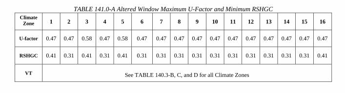
2013 Building Energy Efficiency Standards Page 198
SECTION 141.0 – ADDITIONS, ALTERATIONS, AND REPAIRS TO EXISTING BUILDINGS THAT WILL BE NONRESIDENTIAL, HIGH-RISE RESIDENTIAL, AND HOTEL/MOTEL OCCUPANCIES AND TO EXISTING OUTDOOR LIGHTING FOR THESE OCCUPANCIES AND TO INTERNALLY AND EXTERNALLY ILLUMINATED SI
TABLE 141.0-A Altered Window Maximum U-Factor and Minimum RSHGC
B. Existing roofs being replaced, recovered or recoated, of a nonresidential, high-rise residential and hotels/motels shall meet the requirements of Section 110.8(i). Roofs with more than 50 percent of the roof area or more than 2,000 square feet of roof, whichever is less, is being altered the requirements of i through iii below apply:
i. Roofing Products. Nonresidential buildings:
a. Low-sloped roofs in Climate Zones 1 through16 shall have a minimum aged solar reflectance of 0.63 and a minimum thermal emittance of 0.75, or a minimum SRI of 75.
b. Steep-sloped roofs in Climate Zones 1 through16 shall have a minimum aged solar reflectance of 0.20 and a minimum thermal emittance of 0.75, or a minimum SRI of 16.
EXCEPTION to Section 141.0(b)2Bia: An aged solar reflectance less than 0.63 is allowed provided the maximum roof/ceiling U-factor in TABLE 141.0-B is not exceeded.
ii. Roofing Products. High-rise residential buildings and hotels and motels:
a. Low-sloped roofs in Climate Zones 10, 11, 13, 14 and 15 shall have a minimum aged solar reflectance of 0.55 and a minimum thermal emittance of 0.75, or a minimum SRI of 64.
b. Steep-sloped roofs Climate Zones 2 through 15 shall have a minimum aged solar reflectance of 0.20 and a minimum thermal emittance of 0.75, or a minimum SRI of 16.
EXCEPTION 1 to Section 141.0(b)2Bi and ii: Roof area covered by building integrated photovoltaic panels and building integrated solar thermal panels are not required to meet the minimum requirements for solar reflectance, thermal emittance, or SRI.
EXCEPTION 2 to Section 141.0(b)2Bi and ii: Roof constructions that have thermal mass over the roof membrane with a weight of at least 25 lb/ft² are not required to meet the minimum requirements for solar reflectance, thermal emittance, or SRI.
Climate Zone 1 2 3 4 5 6 7 8 9 10 11 12 13 14 15 16
U-factor 0.47 0.47 0.58 0.47 0.58 0.47 0.47 0.47 0.47 0.47 0.47 0.47 0.47 0.47 0.47 0.47
RSHGC 0.41 0.31 0.41 0.31 0.41 0.31 0.31 0.31 0.31 0.31 0.31 0.31 0.31 0.31 0.31 0.41
VT See TABLE 140.3-B, C, and D for all Climate Zones

C A L I F O R N I A E N E R G Y C O M M I S S I O N65
§141.0(b)2A and the Permit ProcessProcess
• Verify at permit on NRCC-ENV 01ENV-01
Verify efficiency values and glazing area meet reqs.g g q
• Verify at FinalReplaced/added fen meetsReplaced/added fen. meets values/areas on NRCC-ENV-01
NRCI-ENV-01 form
NRCA-ENV-02 req. if site-built fenestration installed
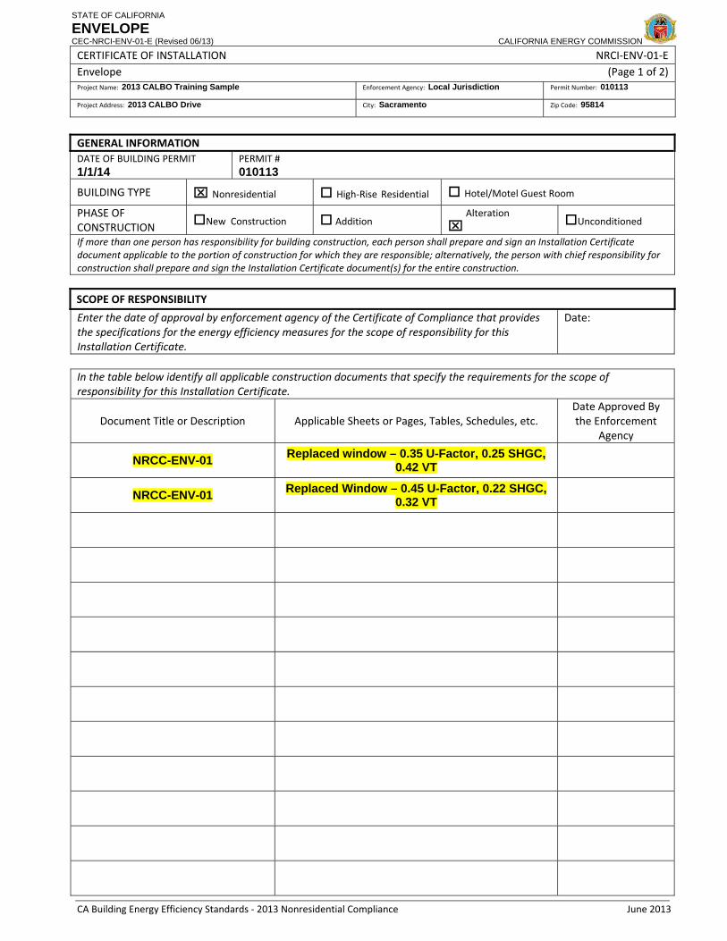
STATE OF CALIFORNIA
ENVELOPE CEC-NRCI-ENV-01-E (Revised 06/13) CALIFORNIA ENERGY COMMISSION
CERTIFICATE OF INSTALLATION NRCI‐ENV‐01‐E Envelope (Page 1 of 2)Project Name: 2013 CALBO Training Sample Enforcement Agency: Local Jurisdiction Permit Number: 010113
Project Address: 2013 CALBO Drive City: Sacramento Zip Code: 95814
CA Building Energy Efficiency Standards ‐ 2013 Nonresidential Compliance June 2013
GENERAL INFORMATION DATE OF BUILDING PERMIT 1/1/14
PERMIT # 010113
BUILDING TYPE ⌧ Nonresidential
High‐Rise Residential Hotel/Motel Guest Room
PHASE OF CONSTRUCTION New Construction Addition ⌧
Alteration Unconditioned
If more than one person has responsibility for building construction, each person shall prepare and sign an Installation Certificate document applicable to the portion of construction for which they are responsible; alternatively, the person with chief responsibility for construction shall prepare and sign the Installation Certificate document(s) for the entire construction.
SCOPE OF RESPONSIBILITY
Enter the date of approval by enforcement agency of the Certificate of Compliance that provides the specifications for the energy efficiency measures for the scope of responsibility for this Installation Certificate.
Date:
In the table below identify all applicable construction documents that specify the requirements for the scope of responsibility for this Installation Certificate.
Document Title or Description Applicable Sheets or Pages, Tables, Schedules, etc. Date Approved By the Enforcement
Agency
NRCC-ENV-01 Replaced window – 0.35 U-Factor, 0.25 SHGC, 0.42 VT
NRCC-ENV-01 Replaced Window – 0.45 U-Factor, 0.22 SHGC, 0.32 VT

C A L I F O R N I A E N E R G Y C O M M I S S I O N66
Re-roofs2008 – §149(b)1B
• When more than 50% or 2
2013 – §141.0(b)2B• Same threshold criteria
2,000 ft2 replaced (whichever is less), must be cool roof
Same efficiency reqs. as prescriptive reqs. for new construction
Same as prescriptive reqs. for both low-sloped and steep-l d f ( t )
construction
Remember that density criteria was removed
sloped roofs (new const.)
Roof insulation alternative in TABLE 149-A
• Solar reflectance trade-off in TABLE 141.0-B

2013 Building Energy Efficiency Standards Page 199
SECTION 141.0 – ADDITIONS, ALTERATIONS, AND REPAIRS TO EXISTING BUILDINGS THAT WILL BE NONRESIDENTIAL, HIGH-RISE RESIDENTIAL, AND HOTEL/MOTEL OCCUPANCIES AND TO EXISTING OUTDOOR LIGHTING FOR THESE OCCUPANCIES AND TO INTERNALLY AND EXTERNALLY ILLUMINATED SI
TABLE 141.0-B Roof/Ceiling Insulation Tradeoff for Aged Solar Reflectance
Aged Solar Reflectance
Climate Zone 1, 3‐9
U‐factor
Climate Zone 2, 10‐
16 U‐factor
0.62‐ 0.60 0.075 0.052
0.59‐0.55 0.066 0.048
0.54‐0.50 0.060 0.044
0.49‐0.45 0.055 0.041
0.44‐0.40 0.051 0.039
0.39‐0.35 0.047 0.037
0.34‐0.30 0.044 0.035
0.29‐0.25 0.042 0.034
iii. For nonresidential buildings, high-rise residential buildings and hotels and motels, when roofs are exposed to the roof deck, or to the roof recover boards and meets Section 141.0(b)2Bi and ii the exposed area shall be insulated to the levels specified in TABLE 141.0-C.
EXCEPTION to Section 141.0(b)2Biii
a. Existing roofs that are insulated with at least R-7 insulation or it has a U-factor lower than 0.089 are not required to meet the R-value requirement of TABLE 141.0-C.
b. If mechanical equipment is located on the roof and will not be disconnected and lifted as part of the roof replacement, insulation added may be limited to the maximum insulation thickness that will allow a height of 8 inches (203 mm) from the roof membrane surface to the top of the base flashing.
c. If adding the required insulation will reduce the base flashing height to less than 8 inches (203 mm) at penthouse or parapet walls, the insulation added may be limited to the maximum insulation thickness that will allow a height of 8 inches (203 mm) from the roof membrane surface to the top of the base flashing, provided that the conditions in Subsections i through iv apply:
i. The penthouse or parapet walls are finished with an exterior cladding material other than the roofing covering membrane material; and
ii. The penthouse or parapet walls have exterior cladding material that must be removed to install the new roof covering membrane to maintain a base flashing height of 8 inches (203 mm); and
iii. For nonresidential buildings, the ratio of the replaced roof area to the linear dimension of affected penthouse or parapet walls shall be less than 25 square feet per linear foot for Climate Zones 2, and 10 through 16, and less than 100 square feet per linear foot for Climate Zones 1, and 3 though 9; and

C A L I F O R N I A E N E R G Y C O M M I S S I O N67
§141.0(b)2B and the Permit ProcessProcess
• Verify at permit on NRCC ENV 01 (S ti E)NRCC-ENV-01 (Section E)
Verify SR and TE values meet requirements q
Verify if alternative is used
• Verify at Final• Verify at Final
Installed cool roof values meet or exceed NRCC-ENV-01or exceed NRCC ENV 01
(CRRC product label)
Verify NRCI-ENV-02

STATE OF CALIFORNIA
ENVELOPE CEC-NRCI-ENV-01-E (Revised 06/13) CALIFORNIA ENERGY COMMISSION
CERTIFICATE OF INSTALLATION NRCI‐ENV‐01‐E Envelope (Page 1 of 2)Project Name: 2013 CALBO Training Sample Enforcement Agency: Local Jurisdiction Permit Number: 010113
Project Address: 2013 CALBO Drive City: Sacramento Zip Code: 95814
CA Building Energy Efficiency Standards ‐ 2013 Nonresidential Compliance June 2013
GENERAL INFORMATION DATE OF BUILDING PERMIT 1/1/14
PERMIT # 010113
BUILDING TYPE ⌧ Nonresidential
High‐Rise Residential Hotel/Motel Guest Room
PHASE OF CONSTRUCTION New Construction Addition ⌧
Alteration Unconditioned
If more than one person has responsibility for building construction, each person shall prepare and sign an Installation Certificate document applicable to the portion of construction for which they are responsible; alternatively, the person with chief responsibility for construction shall prepare and sign the Installation Certificate document(s) for the entire construction.
SCOPE OF RESPONSIBILITY
Enter the date of approval by enforcement agency of the Certificate of Compliance that provides the specifications for the energy efficiency measures for the scope of responsibility for this Installation Certificate.
Date:
In the table below identify all applicable construction documents that specify the requirements for the scope of responsibility for this Installation Certificate.
Document Title or Description Applicable Sheets or Pages, Tables, Schedules, etc. Date Approved By the Enforcement
Agency
NRCC-ENV-01 Cool Roof – Single Ply, 0.65 Aged Solar Reflectance, 0.80 Thermal Emittance

C A L I F O R N I A E N E R G Y C O M M I S S I O N68
HVAC Alterations2008 – §149(b)1C, D, E
• Reqs. for
2013 – §141.0(b)2C, D, E• Reqs./criteria for all HVAC
New space conditioning systems
alterations did not change
• Acceptance testing will need Duct alterations
HVAC changeouts
to be performed by a CMATT when req.
Duct leakage testing
Acceptance testing
• Forms will need to be registered starting 1/1/15
f• MECH-1C-ALT from • NRCC-MCH-ALT form under development

C A L I F O R N I A E N E R G Y C O M M I S S I O N69
§141.0(b)2C, D, E and the Permit ProcessPermit Process
• Verify at permit on NRCC-MCH-ALTMCH-ALT
Should verify HVAC type and req. Acceptance tests
• Verify at Final:NRCA-MCH-02 (new systems)( y )NRCA-MCH-04 and NRCV-MCH-04 (duct leakage)NRCA-MCH-05 (economizers)NRCA-MCH-05 (economizers)
NRCA forms must be signed my CMATT when req. * Forms must be registered starting 1/1/15

STATE OF CALIFORNIA
OUTDOOR AIR ACCEPTANCE CEC-NRCA-MCH-02-A (Revised 06/13) CALIFORNIA ENERGY COMMISSION
CERTIFICATE OF ACCEPTANCE NRCA‐MCH‐02‐A Outdoor Air Acceptance (Page 2 of 3)Project Name: 2013 CALBO Training Sample Enforcement Agency: Local Jurisdiction Permit Number: 010113
Project Address: 2013 CALBO Drive City: Sacramento Zip Code: 95814
CA Building Energy Efficiency Standards ‐ 2013 Nonresidential Compliance June 2013
� 3 complete air changes to the zone served by the air handler.
NA7.5.1.1 Outdoor Air Acceptance
A. Functional Testing (Check appropriate column) ⌧ CAV � VAV
Step 1: Verify unit is not in economizer mode during test (economizer disabled). ⌧ �
Note: Shaded boxes do not apply for CAV systems
Step 2: CAV and VAV testing at full supply airflow
a. Adjust supply air to achieve design airflow or maximum airflow at full cooling. Record VFD speed (Hz).
Hz
b. Measured outdoor airflow reading (cfm) 325 cfm cfm
c. Required outdoor airflow (cfm) (from MECH‐3C, Column I, or Mechanical Equipment Schedules).
300 cfm cfm
d. Time for outside air damper to stabilize after full supply airflow is achieved (minutes): min
Step 3: VAV testing at reduced supply airflow CAV VAV
a. Adjust supply airflow to either the sum of the minimum zone airflows, full heating, or 30% of the total design airflow. Record VFD speed (Hz).
Hz
b. Measured outdoor airflow reading (cfm) cfm c. Required outdoor airflow (cfm) (from MECH‐3C, Column I, or mechanical equipment schedules). cfm d. Time for outside air damper to stabilize after reduced supply airflow is achieved (minutes): min Step 4: Return to initial conditions (check) ⌧ �
B. Testing Calculations & Results
Determine Percent Outside Air at full supply airflow (%OAFA) for Step 2
a. %OAFA = Measured outdoor airflow reading /Required outdoor airflow (Step2b/Step2c) 108 % %
b. %OAFA is within 10% of design Outside Air. (90% ≤ %OAFA ≤ 110%) Y / N Y / N
c. Outside air damper position stabilizes within 5 minutes (Step 2d < 5 minutes) Y / N
Determine Percent Outside Air at reduced supply airflow (%OARA) for Step 3 (VAV only)
a. %OARA = Measured outdoor airflow reading /Required outdoor airflow reading (Step3b/Step3c) %
b. %OARA is within 10% of design Outside Air. (90% ≤ %OARA ≤ 110%) Y / N
c. Outside air damper position stabilizes within 5 minutes (Step 3d < 5 minutes) Y / N
Note: The intent of this test is to ensure that 1) all air handlers provide the minimum amount of OSA and 2) VAV air handlers use dynamic controls to avoid over ventilation.
C. Evaluation :
⌧ PASS: All Construction Inspection responses are complete and Testing Calculations & Results responses are positive (Y ‐ yes)

STATE OF CALIFORNIA
DUCT LEAKAGE DIAGNOSTIC TEST CEC-NRCV-MCH-04-H (Revised 06/13) CALIFORNIA ENERGY COMMISSION
CERTIFICATE OF VERIFICATION NRCV‐MCH‐04‐H Duct Leakage Diagnostic Test (Page 1 of 2)Project Name: 2013 CALBO Training Sample Enforcement Agency: Local Jurisdiction Permit Number: 010113
Project Address: 2013 CALBO Drive City: Sacramento Zip Code: 95814
Registration Number: Registration Date/Time: HERS Provider: CA Building Energy Efficiency Standards ‐ 2013 Nonresidential Compliance June 2013
A. System Information
01 HVAC System Identification or Name: HVAC 1 02 HVAC System Location or Area Served: First Floor
03 Verified Low Leakage Air‐handling Unit Credit from NRCC‐PRF‐01‐E?
N/A
04 Duct System Compliance Category: Alteration B. Duct Leakage Diagnostic Test ‐ MCH‐04d ‐ Alteration
01 Condenser Nominal Cooling Capacity (ton) 2.5 tons 02 Heating Capacity (kBtu/h) 80,000 Btu/h 03 LeakageFactor ( ) .15
04 Air‐Handling Unit Airflow (AHUAirflow) Determination Method
Cooling System Method
05 Calculated Target Allowable Duct Leakage Rate (cfm)
150 cfm
06 Actual duct leakage rate from leakage test measurement (cfm)
100 cfm
07 Compliance statement: System Passes Leakage Test C. ADDITIONAL REQUIREMENTS FOR COMPLIANCE
The responsible persons signature on this document indicates the installation complies with the following requirements:
01 System was tested in its normal operation condition. No temporary taping allowed.
02 All supply and return register boots were sealed to the drywall.
03 If cloth backed tape was used it was covered with Mastic and draw bands.
04 All connection points between the air handler and the supply and return plenums are completely sealed.
05 For all supply and return registers, verify that the spaces between the register boot and the interior finishing wall are properly sealed.

C A L I F O R N I A E N E R G Y C O M M I S S I O N70
Lighting Alterations2008 – §149(b)1I
• Must meet mandatory and
2013 – §141.0(b)2I• Lighting system alterations
prescriptive reqs. for alterations:
Th t i th li hti l d
must meet reqs. in TABLE 141.0-E
Threshold criteria of 10% for That increase the lighting load (watts/ft2)
Where 50% or more of the
%altered fixtures
• Luminaire modifications-in-lighting fixtures are replaced, removed, or re-installed
• Must meet mandatory reqs
place must meet reqs. in TABLE 141.0-F
Threshold criteria of 40 • Must meet mandatory reqs. for wiring alterations
luminaires for altered fixtures
• Acceptance test by CLCATT

2013 Building Energy Efficiency Standards Page 201
SECTION 141.0 – ADDITIONS, ALTERATIONS, AND REPAIRS TO EXISTING BUILDINGS THAT WILL BE NONRESIDENTIAL, HIGH-RISE RESIDENTIAL, AND HOTEL/MOTEL OCCUPANCIES AND TO EXISTING OUTDOOR LIGHTING FOR THESE OCCUPANCIES AND TO INTERNALLY AND EXTERNALLY ILLUMINATED SI
ii. If the new ducts are an extension of an existing duct system, the combined new and existing duct system shall meet one of the following requirements:
a. The measured duct leakage shall be equal to or less than 15 percent of the system air handler airflow as confirmed by field verification and diagnostic testing utilizing the procedures in Reference Nonresidential Appendix Section NA2.1.4.2.1; or
b. If it is not possible to comply with the duct leakage criterion in Subsection 141.0(b)2Diia, then all accessible leaks shall be sealed and verified through a visual inspection and a smoke test performed by a certified HERS Rater utilizing the methods specified in Reference Nonresidential Appendix NA2.1.4.2.2.
EXCEPTION to Section 141.0(b)2Dii: Duct Sealing. Existing duct systems that are extended, which are constructed, insulated or sealed with asbestos are exempt from the requirements of subsection 141.0(b)2Dii.
E. Altered Space-Conditioning Systems. When a space-conditioning system is altered by the installation or replacement of space-conditioning system equipment (including replacement of the air handler, outdoor condensing unit of a split system air conditioner or heat pump, or cooling or heating coil):
i. For all altered units where the existing thermostat does not comply with Reference Joint Appendix JA5, the existing thermostat shall be replaced with a thermostat that complies with Reference Joint Appendix JA5. All newly installed space-conditioning systems requiring a thermostat shall be equipped with a thermostat that complies with Reference Joint Appendix JA5; and
ii. The duct system that is connected to the new or replaced space-conditioning system equipment shall be sealed, if the duct system meets the criteria of Sections 140.4(l)1, 2 and 3, as confirmed through field verification and diagnostic testing, in accordance with the applicable procedures for duct sealing of altered existing duct systems as specified in Reference Nonresidential Appendix NA2, and conforming to the applicable leakage compliance criteria in Section 141.0(b)2D.
EXCEPTION 1 to Section 141.0(b)2E: Duct Sealing. Buildings altered so that the duct system no longer meets the criteria of Sections 144 (l)1, 2, and 3 are exempt from the requirements of Subsection 141.0(b)2E.
EXCEPTION 2 to Section 141.0(b)2E: Duct Sealing. Duct systems that are documented to have been previously sealed as confirmed through field verification and diagnostic testing in accordance with procedures in the Reference Nonresidential Appendix NA2 are exempt from the requirements of Subsection 141.0(b)2E.
EXCEPTION 3 to Section 141.0(b)2E: Duct Sealing. Existing duct systems constructed, insulated or sealed with asbestos are exempt from the requirements of Subsection 141.0(b)2E.
F. Spaces with lighting systems installed for the first time shall meet the requirements of Sections 110.9, 130.0, 130.1, 130.2, 130.4, 130.5, 140.3(c), 140.6, and 140.7.
G. When the requirements of Section 130.1(d) are triggered by the addition of skylights to an existing building and the lighting system is not re-circuited, the daylighting control need not meet the multi-level requirements in Section 130.1(d).
H. New internally and externally illuminated signs shall meet the requirements of Sections 110.9, 130.3 and 140.8.
I. For each enclosed space, alterations to existing indoor lighting shall meet the following requirements:
i. Luminaire Classification and Power shall be determined in accordance with Section 130.0(c).
EXCEPTION to Section 141.0(b)2Ii: For only a Lighting System Alteration in accordance with Section 141.0(b)2Iii, or a Luminaire Modifications-in-Place in accordance with Section 141.0(b)2Iiii; an existing incandescent, fluorescent or HID luminaire may be modified and classified as a luminaire having a different number of, or type of light source(s), provided all of the following conditions are met:
a. The luminaire has been previously used and is in an existing installation; and,

2013 Building Energy Efficiency Standards Page 202
SECTION 141.0 – ADDITIONS, ALTERATIONS, AND REPAIRS TO EXISTING BUILDINGS THAT WILL BE NONRESIDENTIAL, HIGH-RISE RESIDENTIAL, AND HOTEL/MOTEL OCCUPANCIES AND TO EXISTING OUTDOOR LIGHTING FOR THESE OCCUPANCIES AND TO INTERNALLY AND EXTERNALLY ILLUMINATED SI
b. The modified luminaire is listed with the different number or type of light source(s) under the installed conditions; and
c. The different light source(s) is not an LED lamp, integrated or nonintegrated type, as defined by ANI/IES RP-16-2010; and
d. The modified luminaire does not contain:
1. Unused fluorescent or HID ballast(s); or
2. Unused HID or fluorescent lamp sockets; or
3. Sockets used only for lamp support; or
4. Screw sockets of any kind or for any purpose; and
e. The wattage of the modified luminaire shall be published in the manufacturer’s catalog based on accredited testing lab reports.
ii. Lighting System Alterations shall meet the applicable requirements in TABLE 141.0-E and the following:
a. Lighting System Alterations include alterations where an existing lighting system is modified, luminaires are replaced, or luminaires are disconnected from the circuit, removed and reinstalled, whether in the same location or installed elsewhere.
EXCEPTION 1 to Section 141.0(b)2Iii: Alterations that qualify as a Luminaire Modification-in-Place.
EXCEPTION 2 to Section 141.0(b)2Iii: Portable luminaires, luminaires affixed to moveable partitions, and lighting excluded in accordance to Section 140.6(a)3.
iii. Luminaire Modifications-in-Place shall meet the applicable requirements in TABLE 141.0-F and the following:
a. To qualify as a Luminaire Modification-in-Place, luminaires shall only be modified by one or more of the following methods:
1. Replacing lamps and ballasts with like type or quantity in a manner that preserves the original luminaire listing.
2. Changing the number or type of light source in a luminaire including: socket renewal, removal or relocation of sockets or lampholders, and/or related wiring internal to the luminaire including the addition of safety disconnecting devices.
3. Changing the optical system of a luminaire in part or in whole.
4. Replacement of whole luminaires one for one in which the only electrical modification involves disconnecting the existing luminaire and reconnecting the replacement luminaire.
b. Luminaire Modifications-In-Place shall include only alterations to lighting system meeting the following conditions:
1. Luminaire Modifications-in-Place shall not be part of or the result of any general remodeling or renovation of the enclosed space in which they are located.
2. Luminaire Modifications-in-Place shall not cause, be the result of, or involve any changes to the panelboard or branch circuit wiring, including line voltage switches, relays, contactors, dimmers and other control devices providing power to the lighting system.
EXCEPTION to Section 141.0(b)2Iiii2. Circuit modifications strictly limited to the addition of occupancy or vacancy sensors and class two lighting controls are permitted for Luminaire Modifications-in-Place
iv. Lighting Wiring Alterations shall meet the applicable requirements in Sections 110.9, 130.1, and 130.4.

2013 Building Energy Efficiency Standards Page 203
SECTION 141.0 – ADDITIONS, ALTERATIONS, AND REPAIRS TO EXISTING BUILDINGS THAT WILL BE NONRESIDENTIAL, HIGH-RISE RESIDENTIAL, AND HOTEL/MOTEL OCCUPANCIES AND TO EXISTING OUTDOOR LIGHTING FOR THESE OCCUPANCIES AND TO INTERNALLY AND EXTERNALLY ILLUMINATED SI
a. Lighting Wiring Alterations include the following:
1. Adding a circuit feeding luminaires.
2. Modifying or relocating wiring to provide power to new or relocated luminaires.
3. Replacing wiring between a switch or panelboard and luminaire(s).
4. Replacing or installing a new panelboard feeding lighting systems.
EXCEPTION to Section 141.0(b)2Iiv. Lighting Wiring Alterations allowed for Luminaire Modifications-in-Place in accordance with Section 141.0(b)2Iiii.
v. Any lighting alteration that increases the installed lighting power in an enclosed space shall meet the requirements of Sections 110.9, 130.0, 130.1, 130.4, 140.3(c) and 140.6.
vi. Lighting Alterations and Luminaire Modifications-in-Place shall not exceed the lighting power allowance in Section 140.6.
vii. The following indoor lighting alterations are not required to comply with the lighting requirements in Title 24, Part 6:
a. Replacement in kind of parts of an existing luminaire that include only new lamps, lamp holders, or lenses, when replacement of those parts is not a Luminaire-Modification-in-Place in accordance with Section 141.0(b)2Iiii.
b. Lighting Alterations directly caused by the disturbance of asbestos.
EXCEPTION to Section 141.0(b)2Iviib: Lighting alterations made in conjunction with asbestos abatement shall comply with the applicable requirements in Section 141.0(b)2I.
J. Alterations to existing outdoor lighting systems shall meet the following requirements:
i. Alterations that increase the connected lighting load in a lighting application listed in TABLE 140.7-A or 140.7-B shall meet the applicable requirements of Sections 130.0, 130.2, 130.4, and 140.7; and
ii. In alterations that replace 10 percent or more of the luminaires in a lighting application listed in TABLE 140.7-A or 140.7-B, the altered luminaires shall meet the applicable requirements of Sections 130.0, 130.2 and 130.4; and
iii. In alterations that replace more than 50 percent of the luminaires in a lighting application listed in TABLE 140.7-A or 140.7-B, the lighting in that application shall meet the applicable requirements of Sections 130.0, 130.2, 130.4 and 140.7.
K. Alterations to existing internally and externally illuminated signs that increase the connected lighting load, replace and rewire more than 50 percent of the ballasts, or relocate the sign to a different location on the same site or on a different site shall meet the requirements of Section 140.8
L. Replacement of parts of an existing sign, including replacing lamps, the sign face or ballasts, that do not require rewiring or that are done at a time other than when the sign is relocated, is not an alteration subject to the requirements of Section 141.0(b)2K.
M. Service water-heating systems shall meet the requirements of Section 140.5, except for the solar water heating requirements.
N. A building shell for which interior walls or ceilings are installed for the first time shall meet the requirements of Section 140.3(c)
3. Performance approach.
A. The altered envelope, space–conditioning system, lighting and water heating components, and any newly installed equipment serving the alteration, shall meet the applicable requirements of Sections 110.0 through 110.9, Sections 120.0 through 120.6, and Sections 120.8 through 130.5.
EXCEPTION to Section 141.0(b)3A Window Films. Applied window films installed as part of an alteration complies with the U-factor, RSHGC and VT requirements of TABLE 141.0-D.

2013 Building Energy Efficiency Standards Page 206
SECTION 141.0 – ADDITIONS, ALTERATIONS, AND REPAIRS TO EXISTING BUILDINGS THAT WILL BE NONRESIDENTIAL, HIGH-RISE RESIDENTIAL, AND HOTEL/MOTEL OCCUPANCIES AND TO EXISTING OUTDOOR LIGHTING FOR THESE OCCUPANCIES AND TO INTERNALLY AND EXTERNALLY ILLUMINATED SI
TABLE 141.0-E Requirements for Luminaire Alterations Quantity of existing affected luminaires
per Enclosed Space 1
Resulting Lighting Power for Each Enclosed Space
Applicable Mandatory Control Provisions for Each Enclosed
Space
Multi-level Lighting Control Requirements for Each Altered
Luminaire
Alterations that do not change the area of the enclosed space or the space type
Sum total < 10% of existing luminaires
Existing lighting power is permitted Existing provisions are permitted Existing controls are permitted
Sum total ≥ 10% of existing luminaires
≤ 85% of allowed lighting power per Section 140.6 Area Category
Method
§130.1(a), (c)
Two level lighting control 2
or §130.1(b)
> 85% of allowed lighting power per Section 140.6 Area Category
Method
§130.1(a), (c), (d) 3
§130.1(b)
Alterations that change the area of the enclosed space or the space type or increase the lighting power in the enclosed space
Any number Comply with Section 140.6 §130.0(d) 3
§130.1(a), (c), (d) 3, (e) §130.1(b)
1. Affected luminaires include any luminaire that is changed, replaced, removed, relocated; or, connected to, altered or revised wiring, except as permitted by EXCEPTIONS 1 and 2 to Section 141.0(b)2Iii: 2. Two level lighting control shall have at least one control step between 30 percent and 70 percent of design lighting power in a manner providing reasonably uniform illuminations 3. Daylight controls in accordance with Section 130.0(d) are required only for luminaires that are altered.
TABLE 141.0-F Requirements for Luminaire Modifications-in-Place For compliance with this Table, building space is defined as any of the following: 1. A complete single story building 2. A complete floor of a multifloor building 3. The entire space in a building of a single tenant under a single lease 4. All of the common, not leasable space in single building
Quantity of affected luminaires per Building Space per annum
Resulting Lighting Power per Each Enclosed Space Where
≥ 10% of Existing Luminaires are Luminaire Modifications-in-Place
Applicable mandatory control provisions for each
enclosed space 1
Applicable multi-level lighting control requirements for each
modified luminaire 2
Sum total < 40 Luminaire Modifications-in-Place
Existing lighting power is permitted Existing provisions are permitted
Existing controls are permitted
Sum total ≥ 40 Luminaire Modifications-in-Place
≤ 85% of allowed lighting power per Section 140.6 Area Category
Method
§130.1(a), (c)
Two level lighting control 3
Or §130.1(b)
> 85% of allowed lighting power per Section 140.6 Area Category
Method
§130.0(d) 4
§130.1(a), (c), (d) 4
§130.1(b)
1. Control requirements only apply to enclosed spaces for which there are Luminaire Modifications-in-Place. 2. Multi-level controls are required only for luminaires for which there are Luminaire Modifications-in-Place. 3. Two level lighting control shall have at least one control step between 30 percent and 70 percent of design lighting power in a manner providing reasonably uniform illuminations. 4. Daylight controls in accordance with Section 130.0(d) are required only for luminaires that are modified-in-place.

C A L I F O R N I A E N E R G Y C O M M I S S I O N71
§141.0(b)2I and the Permit ProcessProcess
• Verify at permit req. Certificate of ComplianceCertificate of Compliance
NRCC-LTI-01 (all alt.)NRCC-LTI-02 (mandatory)( y)NRCC-LTI-03 (watts/ft2)Must match specs. on electrical plansplans
• Verify at Final req. NRCI and NRCA forms
NRCI-LTI-05 (PAF)NRCA-LTI-02 (Controls)

STATE OF CALIFORNIA
INDOOR LIGHTING POWER ALLOWANCE CEC-NRCC-LTI-03-E (Revised 06/13) CALIFORNIA ENERGY COMMISSION
CERTIFICATE OF COMPLIANCE NRCC‐LTI‐03‐E Certificate of Compliance ‐ Indoor Lighting Power Allowance (Page 2 of 4) Project Name: 2013 CALBO Training Sample Date Prepared: 01/01/14
Registration Number: Registration Date/Time: HERS Provider: CA Building Energy Efficiency Standards ‐ 2013 Nonresidential Compliance June 2013
Total Watts. Enter Total Watts into section A, row 2 (Above on this page) .
A separate page must be filled out for Conditioned and Unconditioned Spaces. This page is only for: ⌧ CONDITIONED spaces UNCONDITIONED spaces
C ‐2 AREA CATEGORY METHOD GENERAL LIGHTING POWER ALLOWANCE⌧ Do not include portable lighting for offices. Portable lighting for offices shall be documented only in section B of NRCC‐LTI‐01‐E. ⌧ Separately list lighting for each primary function area as defined in §100.1 of the Standards.
A B C D
AREA CATEGORY (From §140.6 Table 140.6‐C) WATTS PER (ft2) X AREA (ft2)
ALLOWED WATTS Location in Building Primary Function Area per Table 140.6‐C =
Office (First Floor) Office ≤ 250 sq. ft 1.0 250 250 Corridor (Second Floor) Corridor 0.6 100 60

C A L I F O R N I A E N E R G Y C O M M I S S I O N72
For more information2013 St d d W b it t• 2013 Standards Website at:
http://www.energy.ca.gov/title24/2013standards/index.html
CEC t i i (ICC Ch t )• CEC training (ICC Chapters)Contact Energy Standards Hotline at: [email protected]
U ili i i• Utility traininghttp://www.energy.ca.gov/title24/training/
S i i ( i i )• HERS training (Building Departments)http://www.energy.ca.gov/HERS/providers.html
• Ace Web Toolkithttp://energydesignresources.com/resources/software-tools/ace-tools.aspx