Embed Size (px)
Citation preview

NATO STANDARD
ATP-3.3.4.2
AIR-TO-AIR REFUELLING ATP-56
Edition C Version 1
NOVEMBER 2013
NORTH ATLANTIC TREATY ORGANIZATION
ALLIED TACTICAL PUBLICATION
Published by the NATO STANDARDIZATION AGENCY (NSA)
© NATO/OTAN

INTENTIONALLY BLANK

NORTH ATLANTIC TREATY ORGANIZATION
NATO STANDARDIZATION AGENCY (NSA)
NATO LETTER OF PROMULGATION
18 November 2013
1. The enclosed Allied Tactical Publication ATP-3.3.4.2 Edition C Version 1, Air-to-Air Refuelling has been approved by the nations in the MCASB, is promulgated herewith. The agreement of nations to use this publication is recorded in ST ANAG 3971 .
2. ATP-3.3.4.2 Edition C Version 1 is effective upon receipt.
3. No part of this publication may be reproduced, stored in a retrieval system, used commercially, adapted, or transmitted in any form or by any means, electronic, mechanical, photo-copying, recording or otherwise, without the prior permission of the publisher. With the exception of commercial sales, this does not apply to member nations and Partnership for Peace countries, or NATO commands and bodies.
4. This publication shall be handled in accordance with C-M(2002)60.
I
Dr. Cih ngir AKSI/., UR Civ Director, NATO s{~ndardization Agency

INTENTIONALLY BLANK

ATP-3.3.4.2
I Edition C Version 1
RESERVED FOR NATIONAL LETTER OF PROMULGATION

ATP-3.3.4.2
II Edition C Version 1
INTENTIONALLY BLANK

ATP-3.3.4.2
III Edition C Version 1
RECORD OF RESERVATIONS
CHAPTER RECORD OF RESERVATIONS BY NATIONS General USA
Note: The reservations listed on this page include only those that were recorded at time of promulgation and may not be complete. Refer to the NATO Standardization Document Database for the complete list of existing reservations.

ATP-3.3.4.2
IV Edition C Version 1
INTENTIONALLY BLANK

ATP-3.3.4.2
V Edition C Version 1
RECORD OF SPECIFIC RESERVATIONS
NATION SPECIFIC RESERVATIONS
USA ATP-3.3.4.2, page 1-2 and 1-3: Definitions for WARNING and CAUTION are exactly the same. The USA will use the following as the definition for CAUTION: AN OPERATING OR MAINTENANCE PROCEDURE, PRACTICE, OR CONDITION THAT MAY RESULT IN DAMAGE TO AIRCRAFT AND/OR EQUIPMENT.
Note: The reservations listed on this page include only those that were recorded at time of promulgation and may not be complete. Refer to the NATO Standardization Document Database for the complete list of existing reservations.

ATP-3.3.4.2
VI Edition C Version 1
INTENTIONALLY BLANK

ATP-3.3.4.2
IX Edition C Version 1
TABLE OF CONTENTS
Page No.
PRELIMINARIES Cover NSA Letter of Promulgation National Letters of Promulgation Page I Record of Changes Page III Record of Reservations Page V Record of Specific Reservations Page VII Table of Contents Page IX CHAPTER 1 – GENERAL PROCEDURES
SECTION I – INTRODUCTION
1.1. Origin 1-1 1.2. Aim 1-1 1.3. Scope 1-1 1.4. Applicability of Limitations 1-1 1.5. Application 1-2 1.6. Definitions, Terms and Phraseology 1-2 1.7. Additional Information 1-3 1.8. AAR Objectives 1-3 1.9. Combined AAR Operations 1-4
ANNEX 1A - LEXICON Lexicon – Acronyms and Abbreviations 1A-1 Lexicon – Terms and Definitions 1A-2
SECTION II - EMPLOYMENT CONSIDERATIONS AND PRINCIPLES 1.10. Peacetime 1-5 1.11. Combat Operations 1-10 1.12. Tasking 1-10
SECTION III - REFUELLING EQUIPMENT 1.13. Introduction 1-11 1.14. Probe and Drogue 1-11 1.15. Boom 1-14 1.16. Boom Drogue Adapter 1-15 1.17. Fuel Flow Rates and Pressures 1-15 1.18. Tanker Reference Markings 1-15 1.19. Tanker Lighting 1-15

ATP-3.3.4.2
X Edition C Version 1
CHAPTER 2 – FIXED WING PROCEDURES
SECTION I – RENDEZVOUS PROCEDURES 2.1. Introduction 2-1 2.2. General Procedures 2-1 2.3. Visual Acquisition of Tanker 2-4 2.4. Rendezvous Overrun 2-4 2.5. Joining - Probe and Drogue Tankers 2-5 2.6. Refuelling – Probe and Drogue 2-8 2.7. Joining – Boom 2-12 2.8. Refuelling – Boom Tankers 2-12 2.9. Refuelling – Boom Drogue Adaptor (BDA) 2-17 2.10. Leaving 2-18 2.11. Types of RV 2-18 2.12. Equipment Unserviceabilities 2-19
ANNEX 2A - RV ALPHA (ANCHOR RV) 2.A.1. Introduction 2A-1 2.A.2. Procedure 2A-1 2.A.3. Control 2A-2 2.A.4. Anchor Pattern 2A-2 2.A.5. Alternate Anchor Pattern 2A-3
ANNEX 2B – RV BRAVO 2.B.1. Introduction 2B-1 2.B.2. Procedure 2B-1 2.B.3. Control 2B-3
ANNEX 2C – RV CHARLIE 2.C.1. Introduction 2C-1 2.C.2. Procedure 2C-1 2.C.3. Control 2C-3
ANNEX 2D - RV DELTA (POINT PARALLEL) 2.D.1. Introduction 2D-1 2.D.2. Procedure 2D-1 2.D.3. Overtake RV Delta (Point Parallel) 2D-7 2.D.4. Modified RV Delta (Point Parallel) 2D-8
ANNEX 2E - RV ECHO (TIMING) 2.E.1. Introduction 2E-1 2.E.2. Procedure 2E-1 2.E.3. Aids Employed to RV 2E-2
ANNEX 2F - RV FOXTROT (SEQUENCED) 2.F.1. Introduction 2F-1 2.F.2. Accompanied Departure / Buddy Climb 2F-1 2.F.3. Accompanied Departure / Buddy Climb - Planning Considerations 2F-1 2.F.4. Accompanied Departure / Buddy Climb - Implementation 2F-2 2.F.5. Tailchase Departure 2F-2 2.F.6. Tailchase Departure - Planning Considerations 2F-2
ATP-3.3.4.2
XI Edition C Version 1
2.F.7. Tailchase Departure – Establishing ARIP 2F-2 2.F.8. Tailchase Departure – Implementation 2F-2 2.F.9. Receivers Depart Before Tanker 2F-3
ANNEX 2G - RV GOLF (EN ROUTE) 2.G.1. Introduction 2G-1 2.G.2. Basic Procedure 2G-1 2.G.3. Variations in EMCON 2 to Basic Procedure 2G-1 2.G.4. Specific Procedure in EMCON 4 2G-2
SECTION II – FORMATION PROCEDURES 2.13. Introduction 2-20 2.14. Flight Safety 2-20 2.15. Formation Control 2-20 2.16. Wingman/Receiver Responsibilities 2-20 2.17. Airspeeds and Altitudes 2-20 2.18. Weather/Visibility 2-20 2.19. Single Tanker Formations 2-21 2.20. Detailed Formation Procedures 2-22
ANNEX 2H - MULTI-TANKER FORMATION PROCEDURES 2.H.1. Multi-Tanker Formation - Echelon Procedures 2H-1 2.H.2. Formation in Visual Meteorological Conditions (VMC) 2H-2 2.H.3. Formation in Instrument Meteorological Conditions (IMC) - Standard Separated
Formation 2H-3 2.H.4. Tanker Lead Change 2H-4 2.H.5. Multi-Tanker Formation Procedures 2H-5
ANNEX 2I - FORCE EXTENSION PROCEDURES 2.I.1. AAR Deployments (Force Extension) 2I-1 2.I.2. Use of AAR for Force Extension 2I-1 2.I.3. Force Extension Procedures 2I-1
ANNEX 2J - TANKER SNAKE/FORMATION CLIMB GUIDE 2J-1
ANNEX 2K - AAR FORMATION PROCEDURES – HEAVY AIRCRAFT 2.K.1. AAR Formation Procedures – Heavy Aircraft 2K-1 2.K.2. AAR Formation Procedures To Be Used By USAF Heavy Receivers 2K-3
ANNEX 2L - RECEIVER STATION KEEPING EQUIPMENT (SKE) - AAR PROCEDURES
2.L.1. Introduction 2L-1 2.L.2. Pre-Flight Briefing 2L-1 2.L.3. Formation Size and Dimensions 2L-1 2.L.4. Rendezvous 2L-1 2.L.5. Positive Separation 2L-2 2.L.6. Unplanned Turns 2L-2 2.L.7. Separation Criteria 2L-2 2.L.8. Turns Greater than 90 Degrees 2L-2 2.L.9. Formation Irregularities 2L-3 2.L.10. Tanker Echelon 2L-3

ATP-3.3.4.2
XII Edition C Version 1
2.L.11. Conditions for 180 Degree Turns On Track 2L-3 2.L.12. Formation Post Roll-Out 2L-3 2.L.13. Post SKE AAR 2L-4 2.L.14. Breakaway 2L-4 2.L.15. Typical SKE Formations 2L-4
ANNEX 2M - QUICK FLOW PROCEDURES 2.M.1. Quick Flow Procedure (QF) (Boom Only) 2M-1
ANNEX 2N - KC-130 AAR FORMATION PROCEDURES 2.N.1. Introduction 2N-1 2.N.2. Multi-Tanker Rendezvous Procedures 2N-2 2.N.3. Multi-Tanker Formation Procedures 2N-2 2.N.4. Communication Procedures 2N-3 2.N.5. Procedures During IMC 2N-3
SECTION III – ACCOMPANIED LET DOWN PROCEDURES
2.21. General 2-20 2.22. Criteria 2-20 2.23. Considerations 2-20 2.24. Standard Accompanied Let Down 2-21
SECTION IV – SAFETY PROCEDURES 2.25. Introduction 2-22 2.26. Rendezvous 2-22 2.27. Joining – Safety Considerations 2-22 2.28. Refuelling 2-23 2.29. Options to Reduce the Likelihood of Employing Loss of Visual Contact
(Lost Wingman) Procedures 2-27 2.30. Loss of Visual Contact (Lost Wingman) – Receivers on Tanker Wing in
Single Tanker Formation 2-34 2.31. Loss of Visual Contact (Lost Wingman) – Multi Tanker Formation 2-40 2.32. Breakaway 2-41 2.33. Loss of Visual Contact – Receiver(s) in Contact or Astern, or Astern Following a
Breakaway 2-42 2.34. Leaving 2-44 2.35. Aircraft Malfunction 2-44 2.36. Wake Turbulence 2-45 2.37. Fuel Dump 2-45 2.38. Hose Jettison 2-45 2.39. Radar and Weapons 2-46

ATP-3.3.4.2
XIII Edition C Version 1
SECTION V – COMMUNICATIONS 2.40. Security 2-47 2.41. Communications in Multi-Tanker Formations 2-47 2.42. HF Transmission Restrictions 2-47 2.43. IFF/SIF 2-48 2.44. Search and Rescue (SAR) Aircraft 2-48 2.45. AAR Radio Procedures 2-48 2.46. Verbal Communication – Boom AAR Only 2-49 2.47. Boom Envelope Demonstrations 2-49 2.48. Manual and Emergency Boom Latching 2-50 2.49. Fuel Transferred 2-51 2.50. Loss of Radio Contact 2-51 2.51. Emission Control Procedures 2-51 2.52. Radio Silent Procedures 2-51 2.53. Breakaway During Silent Procedures 2-52
ANNEX 2O – EMISSION CONTROL 2O-1
ANNEX 2P – COMMUNICATION PROCEDURES 2P-1
ANNEX 2Q – RADIO SILENT PROCEDURES 2Q-1 CHAPTER 3 – ROTARY WING PROCEDURES
SECTION I – PLANNING AND BRIEFING CONSIDERATIONS - HAAR 3.1. Introduction 3-1 3.2. Planning Considerations 3-1 3.3. Tanker/Receiver Briefing Card 3-5
SECTION II - GENERAL PROCEDURES - HAAR 3.4. General 3-7 3.5. Weather Requirements 3-7 3.6. RV Procedures 3-8 3.7. Join-up Procedures 3-10 3.8. Crossover 3-10 3.9. Contact/Fuel Transfer 3-10 3.10. Receiver Disconnect 3-13 3.11. AAR with One Tanker/Two or More Receivers 3-14 3.12. Multiple Dry Contacts (Training) 3-16 3.13. Completion of AAR 3-16 3.14. En Route/Escort Procedures 3-16 3.15. On-Call (Unplanned) HAAR 3-18 3.16. RV from a Ground Laager 3-18 3.17. No-Shows 3-19 3.18. Types of RV 3-19
ANNEX 3A - RV ALPHA 3A-1

ATP-3.3.4.2
XIV Edition C Version 1
ANNEX 3B – RV BRAVO 3.B.1. Head-On RV 3B-1 3.B.2. Equipment Requirement 3B-1 3.B.3. Method 1 Procedures 3B-1 3.B.4. Method 2 Procedures 3B-3
ANNEX 3C – RV CHARLIE 3C-1
ANNEX 3D - RV DELTA (HEAD-ON OFFSET) 3.D.1. Head-On Offset RV 3D-1 3.D.2. 3D-1 3.D.3. 3D-1 3.D.4. 3D-1
ANNEX 3E - RV ECHO (TANKER ORBIT) 3.E.1. Tanker Orbit RV (VMC Orbit) 3E-1 3.E.2. 3E-1 3.E.3. 3E-1 3.E.4. 3E-1
ANNEX 3F - RV FOXTROT 3F-1
ANNEX 3G - RV GOLF (EN ROUTE) 3.G.1. En Route (Overtaking) RV 3G-1 3.G.2. 3G-1
ANNEX 3H - RV HOTEL (RANDOM) 3.H.1. Random RV 3H-1 3.H.2. 3H-1
SECTION III – FORMATIONS PROCEDURES - HAAR 3.19. HAAR Formation Options 3-20 3.20. HAAR Formation Option 1 3-20 3.21. HAAR Formation Option 2 (Trail) 3-20 3.22. Spare Tanker Position 3-21 3.23. Transition to Spare Tanker 3-22 3.24. Completion of Refuelling 3-22
SECTION IV – SAFETY PROCEDURES - HAAR 3.25. Introduction 3-26 3.26. Unaided HAAR (Non-NVG) 3-26 3.27. Aided HAAR (NVG) 3-27 3.28. Joining – Safety Considerations 3-28 3.29. Lost Contact Procedures 3-29 3.30. Abort Procedures 3-36 3.31. Aircraft Malfunctions 3-36 3.32. Breakaway Procedures 3-37 3.33. Reduced Receiver Flight Performance 3-37 3.34. Lighting 3-38
ATP-3.3.4.2
XV Edition C Version 1
SECTION V – COMMUNICATIONS – HAAR 3.35. Security 3-39 3.36. Communications in Multi-Tanker Formation 3-39 3.37. Minimum Communication Requirement 3-39 3.38. Monitoring Guard 3-40 3.39. Refuelling Frequency Assignments 3-40 3.40. Standard HAAR Terminology 3-40 3.41. EMCON Emitter Procedure 3-40 3.42. EMCON Communication Procedures 3-41 3.43. Escort Operations 3-41 3.44. Radio Silent 3-41
ANNEX 3I – EMCON – HAAR 3I-1 CHAPTER 4 – TILT ROTOR PROCEDURES
SECTION I – PLANNING AND BRIEFING CONSIDERATIONS 4.1. Introduction 4-1 4.2. Planning Considerations 4-2 4.3. Tanker/Receiver Briefing Card 4-6
SECTION II - GENERAL PROCEDURES
4.4. General 4-8 4.5. Weather Requirements 4-8 4.6. RV Procedures 4-9 4.7. Join-up Procedures 4-11 4.8. Crossover/ Cross Under 4-11 4.9. Contact/Fuel Transfer 4-12 4.10. Receiver Disconnect 4-14 4.11. AAR with One Tanker/Two or More Receivers 4-14 4.12. Multiple Dry Contacts (Training) 4-15 4.13. Completion of AAR 4-16 4.14. En Route/Escort Procedures 4-16 4.15. On-Call (Unplanned) TAAR 4-17 4.16. RV from a Ground Laager 4-18 4.17. No-Shows 4-19 4.18. Types of RV 4-19
ANNEX 4A - RV ALPHA 4A-1
ANNEX 4B – RV BRAVO (HEAD-ON) 4B-1
ANNEX 4C – RV CHARLIE 4C-1

ATP-3.3.4.2
XVI Edition C Version 1
ANNEX 4D - RV DELTA (HEAD-ON OFFSET) 4.D.1. Head-On Offset RV 4D-1 4.D.2. 4D-1 4.D.3. 4D-1 4.D.4. 4D-1 4.D.5. 4D-1
ANNEX 4E - RV ECHO (TANKER ORBIT) 4.E.1. Tanker Orbit RV (VMC Orbit) 4E-1 4.E.2. 4E-1 4.E.3. 4E-1 4.E.4. 4E-1
ANNEX 4F - RV FOXTROT 4.F.1. Introduction 4F-1 4.F.2. Accompanied Departure / Buddy Climb 4F-1 4.F.3. Accompanied Departure / Buddy Climb - Planning Considerations 4F-1 4.F.4. Accompanied Departure / Buddy Climb - Implementation 4F-1 4.F.5. Tailchase Departure 4F-2 4.F.6. Tailchase Departure - Planning Considerations 4F-2 4.F.7. Tailchase Departure – Establishing ARIP 4F-2 4.F.8. Tailchase Departure – Implementation 4F-2 4.F.9. Tanker Departs Before Receiver 4F-3
ANNEX 4G - RV GOLF (EN ROUTE) 4.G.1. En Route (Overtaking) RV 4G-1 4.G.2. 4G-1 4.G.3. 4G-1 4.G.4. 4G-1
ANNEX 4H - RV HOTEL (RANDOM) 4.H.1. Random RV 4H-1 4.H.2. 4H-1
SECTION III – FORMATIONS PROCEDURES 4.19. Formation Options 4-20 4.20. Formation Option 1 4-20 4.21. Formation Option 2 (Trail) 4-20 4.22. Spare Tanker Position 4-21 4.23. Transition to Spare Tanker 4-22 4.24. Completion of Refuelling 4-22
SECTION IV – SAFETY PROCEDURES - TAAR 4.25. Introduction 4-24 4.26. Unaided TAAR (Non-NVG) 4-24 4.27. Aided TAAR (NVG) 4-25 4.28. Join-Ups – Safety Considerations 4-26 4.29. Lost Contact Procedures 4-27 4.30. Abort Procedures 4-34 4.31. Aircraft Malfunctions 4-34

ATP-3.3.4.2
XVII Edition C Version 1
4.32. Breakaway Procedures 4-35 4.33. Reduced Receiver Flight Performance 4-35 4.34. Lighting 4-37
SECTION V – COMMUNICATIONS 4.35. Security 4-38 4.36. Communications in Multi-Tanker Formations 4-38 4.37. Minimum Communication Requirements 4-38 4.38. Monitoring Guard 4-38 4.39. Refuelling Frequency Assignments 4-39 4.40. Standard TAAR Terminology 4-39 4.41. EMCON Emitter Procedures 4-40 4.42. EMCON Communication Procedures (as detailed in Chapter 4, Annex 4I) 4-40 4.43. Escort Operations 4-40 4.44. Radio Silent 4-40 ANNEX 4I – EMCON - TAAR 4.I.1. EMCON Criteria 4I-1 4.I.2. Routine EMCON 4I-1 4.I.3. Restrictions under EMCON 2 4I-1 4.I.4. Silent R/T Procedures 4I-1 4.I.5. Emission Out 4I-2 CHAPTER 5 - NATIONAL AND ORGANISATIONAL PROCEDURES PRELIMINARIES Table of Content 5-1 5.1. Introduction 5-1 5.2. Format For National Data published in National SRD (Former Chapter 5 Annexes) 5-1 5.3. Procedure for Making Changes to National SRD 5-3 5.4. POC for Editor for ATP-3.3.4.2 5-3 TANKER CAPABILITIES AND GENERIC CLEARANCES AAR Clearances (Formerly Annex BA) Tanker AAR Capabilities (Formerly Annex BB) Tanker/Receiver Clearance Matrix (Formerly Annex BC)** ** withdrawn

ATP-3.3.4.2
XVIII Edition C Version 1
INTENTIONALLY BLANK

ATP-3.3.4.2
1 - 1 Edition C Version 1
CHAPTER 1 GENERAL PROCEDURES SECTION I - INTRODUCTION
1.1. ORIGIN Many NATO air and maritime air forces have the capability to conduct air-to-air refuelling (AAR) operations. Although detailed procedures are dependent on aircraft type, mode of employment and national requirements, there is sufficient commonality for NATO Standard Procedures to be developed to enhance operational interoperability. 1.2. AIM The aim of this publication is to provide a reference document covering procedures, national AAR equipment and AAR capable aircraft. This will:
a. Provide guidance for NATO and national commanders and staff in order to promote the effective employment of AAR in NATO air operations.
b. Lead to a better understanding of national AAR capabilities amongst
NATO forces. c. Promote mutual AAR support amongst suitably equipped NATO forces. d. Promote the development of mutual AAR tactics and procedures.
1.3. SCOPE This document will address the modes of employment of AAR, the commonality of equipment and identify areas where NATO standardization is practicable. Annexes covering specific national procedures have been incorporated where necessary. 1.4. APPLICABILITY OF LIMITATIONS Where limitations are specified in Chapters 1 to 4 of this document, these are to be considered the baseline for operations between tanker and receiver aircraft from different nations.
a. Tanker Restrictions. In all cases the appropriate National Annex for the participating nation’s tanker is to be consulted to identify if more restrictive limitations apply for the tanker/receiver combination.

ATP-3.3.4.2
1 - 2 Edition C Version 1
b. Receiver National Limitations. Receiver and/or tanker national limitations take precedence over less restrictive limitations published in Chapters 1, 2, 3 or 4 of ATP-56 or the participating tanker’s national annex. Additionally, when working with other nations, the most restrictive of the participant’s national limits or those published in ATP-56 will apply. It is the responsibility of participants to bring such restrictions to the attention of the other party, either through pre-mission contact or verbally prior to commencing AAR.
c. Tanker/Receiver AAR from Same Nation. Nations may publish
less restrictive criteria for their own aircraft when operating together.
1.5. APPLICATION The planning for and employment of AAR should be based on the principles and procedures contained in this document. 1.6. DEFINITIONS, TERMS AND PHRASEOLOGY Definitions, terms and phraseology are listed in the ATP-56 Lexicon at Chapter 1 Annex 1A. Additional national terms and definitions are contained in the corresponding National Annex.
a. Warnings, Cautions and Notes. The following definitions and symbols apply to warnings, cautions and notes found throughout ATP-56.
WARNING
AN OPERATING PROCEDURE, PRACTICE, OR CONDITION THAT MAY RESULT IN INJURY OR DEATH IF NOT CAREFULLY OBSERVED OR FOLLOWED.
!

ATP-3.3.4.2
1 - 3 Edition C Version 1
NOTE
AN OPERATING PROCEDURE, PRACTICE OR CONDITION THAT IS ESSENTIAL TO EMPHASISE. 1.7. ADDITIONAL INFORMATION Additional information on the detailed employment of AAR contained in:
a. ATP-34 - Tactical Air Support of Maritime Operations (TASMO) or Joint Maritime Operations.
b. ACO Manual 80-6.
1.8. AAR OBJECTIVES The objective of AAR operations is to enhance effectiveness by extending the range, payload or endurance of receiver aircraft. Successful AAR depends on 3 major factors:
a. Equipment Compatibility. It is essential that aircraft requiring AAR are fitted with probes/receptacles and fuel systems compatible with the characteristics of the tanker aircraft employed, e.g. drogue/boom system, fuel surge pressures, fuel type etc.
b. Performance Compatibility. It is essential for tanker and receiver
aircraft performance to be compatible in terms of AAR speeds and altitudes.
c. Procedural Compatibility. It is essential for tankers and receivers to
employ pre-planned and compatible procedures for rendezvous, making contact, fuel transfer and departure.
CAUTION
AN OPERATING PROCEDURE, PRACTICE, OR CONDITION THAT MAY RESULT IN INJURY OR DEATH IF NOT CAREFULLY OBSERVED OR FOLLOWED.
!
ATP-3.3.4.2
1 - 4 Edition C Version 1
1.9. COMBINED AAR OPERATIONS Within the constraints of national procedures and equipment characteristics, it is highly desirable that all NATO receivers are able to conduct AAR operations with all NATO tankers on both a pre-planned and/or opportunity basis.

ANNEX 1A to ATP-3.3.4.2
1A - 1 Edition C Version 1
CHAPTER 1 GENERAL PROCEDURES ANNEX 1A LEXICON - ACRONYMS AND ABBREVIATIONS
The Lexicon contains abbreviations relevant to ATP-3.3.4.2 and is not meant to be exhaustive. The definitive and more comprehensive list is in AAP-15. AAR Air-to-Air Refuelling AARA AAR Area AARC AAR Controller AREP AAR Entry Point ARIP AAR Initial Point ARCP AAR Control Point ARCT AAR Control Time ATO Air Tasking Order ATC Air Traffic Control ALTRV Altitude Reservation AOB Angle of Bank AVANA Approval Void if Aircraft Not Airborne BDA Boom Drogue Adapter EMCON Emission Control EUCARF European Centralised Airspace Reservation Facility HAAR Helicopter Air-to-Air Refuelling IDS Independent Disconnect System LOA Letters of Agreement MBL/EBL/OBL Manual / Emergency / Override Boom Latching MARSA Military Assumes Responsibility for Separation of Aircraft MPRS Multi-Point Refuelling System NAAR Night AAR QF Quick Flow AAR RV Rendezvous SKE Station Keeping Equipment SPINS Special Instructions TMO Tanker Manual Override UARRSI Universal AAR Receptacle Slipway Installation WARP Wing AAR Pods

ANNEX 1A to ATP-3.3.4.2
1A - 2 Edition C Version 1
CHAPTER 1 GENERAL PROCEDURES ANNEX 1A LEXICON - TERMS AND DEFINITIONS
AAR Abort Point A planned point along the receiver track at which the receiver must divert, if he is not in contact receiving fuel. AAR Airspeed An airspeed or Mach number at which AAR will be conducted. AAR Area (AARA) A defined area encompassing both a racetrack shape AAR track and its protected airspace. AAR Bracket Designated segment of a route where AAR is planned. The bracket is defined by a refuelling start point and stop point. AAR Control Point (ARCP)(HAAR ONLY) Helicopter Receivers. Normally the earliest point the tanker can pass abeam the receiver during join-up. AAR Control Time (ARCT)(HAAR ONLY) Helicopter Receivers. The planned time that the receiver and tanker will arrive over the ARCP. AAR Element One tanker and one or more receivers. AAR Entry Point (AREP) A designated point at which the receiver enters the anchor area. AAR Envelope The area limits behind a boom equipped tanker within which a receiver must fly to remain in contact. AAR Exit Point (A/R EXIT PT) The designated geographic point at which the refuelling track terminates. AAR Formation (Tanker/Receiver Formation) Two or more tankers and/or receivers operating together with a designated formation leader (See Formation below.).

ANNEX 1A to ATP-3.3.4.2
1A - 3 Edition C Version 1
AAR RV The procedures employed to enable the receiver(s) to reach the astern position behind the assigned tanker(s) (boom) or the observation position (drogue) by electronic, radio, and/or visual means. AAR Stores The refuelling pod, hose and drogue that connects onto the aircraft when configured in the tanker role. AAR System Normal Operation Both tanker and receiver using normal signal system. AAR Time Planned elapsed time from ARCP to completion point. AAR Track A track designated for AAR. Air Tasking Order (ATO) Formatted order detailing all information for the mission. Used to task and disseminate to components, subordinate units, and command and control agencies projected sorties, capabilities and/or forces to targets and specific missions. Air Traffic Control (ATC) A control system that ensures the safe operation of commercial and private aircraft, as well as military aircraft using the same airspace, by co-ordinating the movement of air traffic to ensure they remain a safe distance apart. Alternate AAR Track The track designated for AAR in the event that the primary track cannot be used. Alternate RV A RV achieved when primary means are not available. Alternate means may be radar beacon, common TACAN, Timing, DF Steer, ATC/GCI assistance etc., or any combination of these. Altitude Differential The difference between the receiver altitude and the tanker altitude. Altitude Reservation (ALTRV) An area of airspace reserved for AAR with the appropriate ATC authority. There are 2 types of ALTRV: moving and static. A moving ALTRV encompasses en route activities and advances coincident with the mission progress. A static ALTRV consists of a defined geographic area, specific altitude(s) and time period(s). Amplifier Override Procedure for using receiver override boom latching when receiver air refuelling system malfunctions. Also see Manual Boom Latching.

ANNEX 1A to ATP-3.3.4.2
1A - 4 Edition C Version 1
Anchor Point A defined reference point upon which an anchor refuelling track is orientated. Anchor Refuelling AAR performed as the tanker(s) maintain a prescribed pattern which is anchored to a geographical point or fix (See RVs Alpha and Echo). Anchor RV (RV Alpha) The procedures normally employed by radar (CRC/GCI/AWACS) to vector the tanker(s) and receiver(s) for a visual join-up for refuelling. Angels A brevity code meaning aircraft altitude (in thousands of feet). Approval Void if Aircraft Not Airborne (AVANA) by (time UTC) ALTRV Approval Void for Aircraft Not Airborne by (time). In most cases the AVANA is one hour after the last planned take-off, after which time the ALTRV is automatically cancelled. AR Control Point (ARCP) (Formerly RVCP) The planned geographic point over which the receiver(s) arrive in the observation/astern position with respect to the assigned tanker. AR Control Time (ARCT) (Formerly RVCT) The planned time that the receiver and tanker will arrive over the ARCP. AR Initial Point (ARIP) (Formerly RVIP) A planned geographic point prior to the ARCP to which tankers and receivers time independently to effect an arrival at the RV control time. If the tanker/receiver is not already at its assigned RV FL/ altitude, it commences a climb/descent to that FL/altitude. This point may be a designated position established at the planning or briefing stage, or as directed by the tanker/GCI/AEW controlling the RV. Astern Position
a. Probe and Drogue. The stabilized formation position behind the AAR equipment (approximately 5 ft. directly aft of the drogue) with zero rate of closure.
b. Boom. The position approximately 50 ft. behind and slightly below the
tanker boom nozzle where the receiver stabilizes with zero rate of closure before being cleared to the contact position.
ANNEX 1A to ATP-3.3.4.2
1A - 5 Edition C Version 1
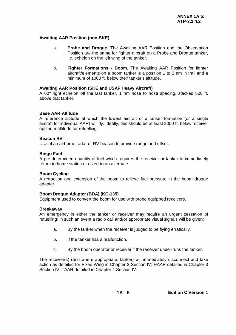
Awaiting AAR Position (non-SKE)
a. Probe and Drogue. The Awaiting AAR Position and the Observation Position are the same for fighter aircraft on a Probe and Drogue tanker, i.e. echelon on the left wing of the tanker.
b. Fighter Formations - Boom. The Awaiting AAR Position for fighter
aircraft/elements on a boom tanker is a position 1 to 3 nm in trail and a minimum of 1000 ft. below their tanker's altitude.
Awaiting AAR Position (SKE and USAF Heavy Aircraft) A 60º right echelon off the last tanker, 1 nm nose to nose spacing, stacked 500 ft. above that tanker. Base AAR Altitude A reference altitude at which the lowest aircraft of a tanker formation (or a single aircraft for individual AAR) will fly. Ideally, this should be at least 2000 ft. below receiver optimum altitude for refuelling. Beacon RV Use of an airborne radar or RV beacon to provide range and offset. Bingo Fuel A pre-determined quantity of fuel which requires the receiver or tanker to immediately return to home station or divert to an alternate. Boom Cycling A retraction and extension of the boom to relieve fuel pressure in the boom drogue adapter. Boom Drogue Adapter (BDA) (KC-135) Equipment used to convert the boom for use with probe equipped receivers. Breakaway An emergency in either the tanker or receiver may require an urgent cessation of refuelling; in such an event a radio call and/or appropriate visual signals will be given:
a. By the tanker when the receiver is judged to be flying erratically. b. If the tanker has a malfunction. c. By the boom operator or receiver if the receiver under-runs the tanker.
The receiver(s) (and where appropriate, tanker) will immediately disconnect and take action as detailed for Fixed Wing in Chapter 2 Section IV; HAAR detailed in Chapter 3 Section IV; TAAR detailed in Chapter 4 Section IV.

ANNEX 1A to ATP-3.3.4.2
1A - 6 Edition C Version 1
Brute Force Disconnect (Boom Only) A disconnect which is the result of a receiver aircraft moving aft to full boom extension and overriding hydraulic pressure or a mechanical malfunction holding the receivers’ toggles in the engaged position. A brute force disconnect may occur inadvertently or as part of a controlled tension disconnect procedure, coordinated between the boom operator and the receiver pilot. Buddy Cruise When tanker(s) and receiver(s) cruise as an AAR element/formation. Buddy Join up Procedure (RV Foxtrot) These procedures are utilized when the tanker(s) and receiver(s) approach the ARIP on a common track by taking off from the same base and joining up. Buddy Takeoff/Departure When tanker and receiver take off and climb as an element/formation. Clear Astern Radio call by the tanker clearing a receiver behind the left/centre/right assigned AAR equipment. The receiver moves to the astern position. Clear Contact (Probe and Drogue and BDA Only) The receiver is cleared to move forward from the astern position to engage the probe in the drogue. Clear Contact Position (Boom Only) The receiver is cleared to advance to the contact position. Clear Join Radio call by the tanker clearing the receiver to join in close formation in the observation position or astern position for boom operations. Clear Leave Radio call given by the tanker clearing the receiver to leave the tanker formation. This call is given only after the receiver has completed the move to the Post AAR Position. Communications Out Radio silent AAR RV operations. All other RV aids may be used. Contact
a. Probe and Drogue, and BDA. A contact is made when the probe engages the drogue.
b. Boom. Called by the boom operator and the receiver when the boom is
locked in the receptacle.

ANNEX 1A to ATP-3.3.4.2
1A - 7 Edition C Version 1
Contact Point The geographical point along the planned AAR track where fuel transfer should commence. Contact Position (Boom Only) The stabilized position of the receiver within the AAR envelope where it is possible to make contact. CONVEX Flying conversion exercises performed to familiarise and qualify aircrew in a new skill set. Crossover (HAAR Only) A specific manoeuvre to reposition a receiver from one side of the tanker to the opposite side. Dead Hose See Hard Hose. Descent Range The distance from the tanker at which the receiver desires to initiate letdown to the tanker. Deployment The relocation of forces and materiel to desired operational areas. Disconnect
a. Action taken by receiver pilot or boom operator to disengage tanker and receiver refuelling systems.
b. Command given by the tanker to receiver, either verbally or by signal,
instructing receiver to disengage from tanker refuelling equipment.
(1) Probe and Drogue, and BDA. The receiver moves smoothly back toward the astern position until the probe disconnects from the drogue.
(2) Boom. When the boom is seen to be clear of the receptacle, the
receiver moves smoothly back to the astern position. Dry Contact AAR engagement for aircrew proficiency during which fuel is not transferred. Echelon Left Position (Fixed Wing Only) The initial formation position for a receiver joining a tanker. This is normally Echelon Left for all receivers.

ANNEX 1A to ATP-3.3.4.2
1A - 8 Edition C Version 1
a. Drogue Equipped Tanker
(1) Availability of Observers. Refer to the tanker’s National Annex to determine if an observer is located in the rear of the aircraft.
(2) Without Refuelling Observers. Receivers should initially be co-
altitude with the tanker, at least one receiver wingspan outboard of the tanker wingtip and well forward, to be observed and identified by the tanker pilots.
(3) With Refuelling Observers. The Echelon Left position for fixed
wing aircraft is stepped down, aft of the tanker wingline and one receiver wingspan outboard of the tanker wing.
b. Boom Equipped Tanker. A position to the left and slightly behind the
tanker wing with a minimum of one receiver wingspan clearance between tanker and receiver (weather permitting). This contrasts with the Awaiting AAR position (see above).
Echelon Left Position (HAAR Only) Helicopter – A position to the left or right of the tanker, outboard of the wingtip and slightly above and behind the tanker horizontal stabilizer. Note: Helicopter receivers should initially RV on the left side of the tanker unless previously briefed or mission dictates otherwise. Echelon Right Area/Position An area to the right and level or slightly above the tanker formation, where receivers other than those moving to the Post AAR Position reform upon completion of AAR.
a. Drogue Equipped Tanker
(1) Availability of Observers. Refer to the tanker’s National Annex to determine if an observer is located in the rear of the aircraft.
(2) No Refuelling Observers. Receivers should initially be co-
altitude with the tanker, at least one receiver wingspan outboard of the right tanker wingtip and well forward, to be observed by the tanker pilots.
(3) With Refuelling Observers. The Echelon Right position for fixed
wing aircraft is level or slightly above the tanker, aft of the tanker wingline and one receiver wingspan outboard of the right tanker wingtip.
b. Boom Equipped Tanker. A position to the right and slightly behind the
tanker wing with a minimum of one receiver wingspan clearance between tanker and receiver (weather permitting).
ANNEX 1A to ATP-3.3.4.2
1A - 9 Edition C Version 1
Electronic Contact (HAAR Only) Electronic data on aircraft/formation location. Operational equipment that provides, at a minimum, range information. Emergency/Override Boom Latching Procedure for using receiver override boom latching when receiver air refuelling system malfunctions. Also see Manual Boom Latching. Emission Control (EMCON) Procedures The management of electromagnetic radiation to counter an enemy’s capability to detect, identify, or locate friendly emitters for exploitation by hostile action For ease of tasking, the restrictions for both equipment emissions and radio transmissions are standardized into 4 Options. These options are detailed in the Communications Sections. Emitter A piece of equipment that emits electromagnetic radiation (radios, radar, TACAN, IFF, Doppler, radio altimeter, etc.). End AAR A planned point or the actual position within the confines of the AAR track at which all AAR operations/requirements are complete. En route Formation (KC-135/KC-10A) Two or more tankers in trail, 1 nm separation, and stacked up at 500 ft. intervals. En route RV (RV Golf) Procedure used when join up is to be achieved en route to the AAR area at the RV position by making good a scheduled time. Timing may be accomplished by utilising an orbit delay or timing triangle. En route RV HAAR (RV Golf) An AAR RV conducted along the receivers’ planned routing. Force Extension Tankers escorting fighters are force extended when they are refuelled en-route to their destination by other tankers which may or may not be part of the formation package. Formation Two or more aircraft with the same intended route or flight, maintaining station-keeping operations by either or both visual and electronic means. The formation will normally be flown with successive tankers in line astern, and stepped up or down behind the leader. Go Echelon Right Radio call given by the tanker which instructs a receiver to move from the astern position to the Echelon Right position after refuelling is complete.

ANNEX 1A to ATP-3.3.4.2
1A - 10 Edition C Version 1
Ground Controlled Intercept (GCI) A ground based radar system through which aircraft are controlled in order to achieve an airborne RV with other aircraft. Hard Hose (Dead Hose) A hose condition in which hose slack is not properly taken up on contact. Any resulting hose whip is likely to damage the receiver’s probe. Hot Armament Forward firing ordnance that can be selected and fired by the receiver pilot or crew. Inadvertent Disconnect (HAAR Only) Unplanned disconnect. Receiver moves to astern position (or as briefed) to await further instructions from tanker. Independent Disconnect System (IDS)(KC-10) The Independent Disconnect System is an electrically controlled, pneumatically actuated system located in the nozzle assembly. It causes the sides of the KC-10 boom nozzle to collapse, allowing the boom to be retracted from the receiver aircraft while its toggles are in the latched extended position. Join Up (HAAR Only) Procedures used to transition the tanker from the RV phase of flight to a position abeam the receiver, ready to assume formation lead and the helicopter(s) ready to move to the observation position. Join Up Altitude (HAAR Only) A helicopter altitude that ensures tanker/receiver altitude separation during the join up. Judy Radio call made by the receiver when radar contact with the tanker and taking over responsibility for closing to within visual range. Manual / Emergency / Override Boom Latching (MBL/EBL/OBL) Procedure for using receiver boom latching when receiver AAR system malfunctions. Both tanker and receiver AAR systems in manual operation. Also known as Emergency/Override Boom Latching and Amplifier Override. Mark A request for the tanker to assist the receiver in achieving visual contact. Depending on type, the tanker may dump a small quantity of fuel, or fire a flare, or switch on/vary the high intensity lighting. Refer to National Annexes. MARSA (FAA Only) Military Assumes Responsibility for Separation of Aircraft - applies only to participating aircraft and FAA controlled formations.

ANNEX 1A to ATP-3.3.4.2
1A - 11 Edition C Version 1
Marshall Stack A predetermined distance from an aircraft carrier in which aircraft hold to await an individual instrument approach to the deck. Marshall radials extend 20 to 45 nm from the carrier. Minimum Safe Altitude (MSA)(HAAR Only) A pre-briefed altitude that provides a vertical clearance from all obstacles within a defined range along a refuelling track. National restrictions determine the mission minimum. Mixed AAR Formation Any formation involving one or more tankers refuelling two or more dissimilar types of aircraft simultaneously. Modified Point Parallel RV (RV Delta) An RV procedure optionally employed when the receiver aircraft is established on-station in a command and control orbit or airspace patrol. The tanker enters the area, effects the RV, and completes the refuelling within the confines of the receiver’s assigned airspace. Multi-Point Refuelling System (MPRS) (KC 135) Self-contained pods mounted on wing-tips of selected KC-135R aircraft that allow a single tanker to support both probe and drogue and boom AAR missions. Night AAR (NAAR) AAR operations that take place between official sunset and sunrise. Normal Communications Normal procedures as established in current AAR orders. All RV aids may be utilised as necessary. Nose Cold Radar selected to standby. Observation (Fixed Wing) No longer in use; now termed Echelon Left. See Echelon Left. Observation Position (Tilt Rotor Only) USAF/AFSOC/USMC differentiates between echelon and observation positions. the echelon position for fixed wing aircraft is stepped down, aft of the tanker wingline and one receiver wingspan outboard of the tanker wing. the observation position is a specific term used in MC-130/KC-130 tanker drogue & probe refuelling community indicating the stable formation position of receiver aircraft, post-join, and utilized prior to sequencing to the astern position.

ANNEX 1A to ATP-3.3.4.2
1A - 12 Edition C Version 1
Observation Position (HAAR Only) Helicopter – A position to the left or right of the tanker, outboard of the wingtip and slightly above and behind the tanker horizontal stabilizer. Note: Helicopter receivers should initially RV on the left side of the tanker unless previously briefed or mission dictates otherwise. Off-load/On-load The tanker fuel, normally established at the planning stage, assigned for off-load/on-load to receiver(s) during an AAR mission. Offset (Track) The lateral distance the tanker is displaced from the ARIP to ARCP track to compensate for turn radius and drift. On-Call (Unplanned AAR) An AAR that has not been planned before the mission, but becomes a requirement due to changing tactical situations. On-Deck Position. (Quick Flow Procedure Only) Left hand echelon formation on the receiver in the contact position. Oral Communications (Boom Only) The following terminology will be used by the boom operator when verbal instructions to the receiver are necessary:
Back Move receiver backward Down Descend receiver. Forward Move receiver forward. Left Move receiver left. Right Move receiver right. Stabilize Hold receiver steady in present position Up Ascend receiver. Slow Closure Called when boom operator perceives an excessive
closure rate. Receiver will reduce aircraft closure rate. Return to Astern Receiver will manoeuvre aircraft to the astern position
and stabilise. Orbit Departure Time That time at which the tanker will depart the orbit point to effect the planned RV. Orbit Pattern The pattern flown by the tanker at the orbit point. Orbit Point A geographic point along the planned AAR track where the tanker will orbit.

ANNEX 1A to ATP-3.3.4.2
1A - 13 Edition C Version 1
Overrun An overrun occurs when the receiver passes the tanker prior to or during the tanker RV turn. Overtaking Point Parallel RV (RV Delta) Same as Point Parallel RV except tanker plans to turn to refuelling track so as to roll out behind the receiver. The tanker then overtakes the receiver and begins a slowdown so as to position the tanker one mile in front of the receiver at AAR Airspeed. Point Parallel RV Procedure (RV Delta) The procedure normally used when the tanker arrives in the AAR area ahead of the receiver (A tanker orbit is normally planned). Post AAR Position The position to be maintained by receiver aircraft upon the completion of AAR.
a. Fighters and Heavy Probe Receivers. See Echelon Right Area/Position.
b. Heavy Boom Receivers. Heavy boom receivers will maintain at least
1000 ft below and no less than 1/2 nm in trail behind the lead tanker (if unable to maintain visual contact, in trail distance is increased to 1 nm). This position will be maintained until clearance is received from Air Traffic Control.
c. Heavy Aircraft Formation (SKE). See Post AAR Position (SKE).
Note: In EMCON other than 3 or 4, tanker lead and receiver will verbally coordinate their respective separation manoeuvres prior to either aircraft departing formation. Post AAR Position (SKE) A 60º left echelon, 2 nm nose to nose separation, stacked down 1000 ft off the lead tanker. Post AAR Procedures The procedures employed by tankers and receivers after final disconnect and prior to establishing cruise. Practice Emergency Separation The term to be used by tanker and receiver aircrews when referring to a Practice Breakaway, prior to accomplishing the manoeuvre. Quick Flow AAR (QF) Visual formation procedures used to expedite AAR operations by minimising required refuelling time.
ANNEX 1A to ATP-3.3.4.2
1A - 14 Edition C Version 1
Radio Silent No radio transmissions between tanker and receiver except in an emergency. For further details see Section V of the respective Chapters 2, 3 and 4. Receiver Holding Point A point along the upstream end of the inbound course to the Anchor Point where the receiver(s) will hold until cleared for RV by the tanker. This point is used during Anchor Refuelling Alternate Procedures. Receiver/Tanker Route Formation (Fighter) Receivers positioned on the tanker with two or four receivers’ wingspan clearance. Refuelling Altitude The briefed AAR altitude that meets the performance and operational requirements of both the tanker and receiver aircraft. Refuelling Heading A true / magnetic / grid heading taken by the tanker(s) and receivers to maintain AAR track. RV Control Point (RVCP) RVCP no longer in use and changed to ARCP, see ARCP. RV Control Time (RVCT) RVCT no longer in use and changed to ARCT, see ARCT. RV Equipment Electronic/radio equipment installed in tanker and receivers for use in achieving an RV. RV FL / Altitude/Height The FL, altitude or height of the tanker during an RV procedure. RV Initial Call When the use of radio is authorized, the tanker is to confirm RV details before starting the RV procedure. The format of the call is in Chapter 2 Annex 2P. RV Initial Point (RVIP) RVIP no longer in use and changed to ARIP, see ARIP. RV Point A designated point where tanker and receiver are planned to be joined in formation (ARCP, ARIP, etc.). RV Procedure A procedure to join the receiver with the tanker. RV Rollout Heading A heading reference taken by the tanker(s) on the final turn towards the RV Point.
ANNEX 1A to ATP-3.3.4.2
1A - 15 Edition C Version 1
RV Speed
a. For RVs where the receiver flies the tanker speed plus 20 kts, the tanker speed (IAS) is known as the RV speed; this is usually the intended refuelling speed (normally optimised for best receiver AAR performance).
Note: If communications are not possible for any reason, and pre-briefing
is not possible, the tanker will fly at the optimum speed for the receiver type as listed in Chapter 5 - SRD Annex BB, TANKER AAR CAPABILITIES.
b. For RVs where the receiver’s speed is known to the tanker, RV Speed is
the speed flown by the receiver when flying towards the tanker for the RV.
RV Track (Tanker Track) The track flown by the tanker during the RV procedure. Receiver(s) track to the RV Point is dependent on planned route and RV procedure. Reverse Flow AAR (boom only) The transfer of fuel from receiver to tanker. Rim The probe strikes the rim or periphery of the drogue but does no damage. Safe Position (KC/KDC-10) The position during a partial or complete boom control system failure that is safe for the boom operator to initiate a disconnect. This position is when the receiver is approximately 0° roll and moving down and back. Station Keeping Equipment (SKE) An avionics based formation management system that allows a large number of aircraft operating on different frequency channels to fly fully instrumented formation in zero visibility. The system can also communicate navigation data and proximity warnings when a threat of collision exists. Participating aircraft can operate within a limited radius of a selected master system on the same frequency. Single Hose Procedure A change to the refuelling procedure which is effected when a tanker, which normally operates with 2 AAR stores, has one store unserviceable. Soft Contact The probe has not fully engaged in the drogue. Special Instructions (SPINS) Special Instructions which are attached to the ATO and detail operating procedures for all missions and tasks.
ANNEX 1A to ATP-3.3.4.2
1A - 16 Edition C Version 1
Spokes The receiver has damaged the drogue. Start Descent Point A point where descent is initiated. Start Point A designated point on track where refuelling of the first receiver(s) is planned to start. Stop Point A designated point on track where refuelling of the last receiver(s) is planned to stop. Switches Safe All Weapons Switches selected to Safe/Off. Tactical Air Control System Any CRC, GCI, or AWACS command and control system. Tactical Stream Two or more AAR formations proceeding at a pre-determined spacing along identical flight paths. Tanker Abeam (HAAR) When receiver is aft of the tanker’s 9 o’clock position during join-up. Tanker Manual Override (TMO) (Boom Only) Receiver AAR system in normal operation, tanker AAR system in manual operation. Tanker Manual Override (TMO) without Tanker Disconnect Capability (Boom Only). Mode of operation used when tanker AAR signal system malfunctions. Receiver AAR system will remain in normal operation. AAR will not be accomplished except during fuel emergencies or when operationally essential. Terminate (Emergency Separation) Call by tanker to cease breakaway manoeuvre. Texaco (HAAR) Brevity term to request a Helicopter Refuelling that can be accomplished on-call. Toboggan Request from receiver for the tanker to start a slow descent, maintaining the refuelling airspeed. The rate of descent is between 300 and 500 ft per min and this should be used unless tanker or receiver requests otherwise. Track Offset Used in RV Delta (Point Parallel), it is the lateral distance which the tanker is offset from the receiver track. The distance compensates for tanker turn radius and drift during the turn towards the ARCP.
ANNEX 1A to ATP-3.3.4.2
1A - 17 Edition C Version 1
Transferable Fuel Tanker fuel available for passing to a receiver. This is the total fuel in the tanker, minus the fuel the tanker requires to recover to an airfield including any landing/diversion/weather reserves. Transmit for DF A 10 sec carrier wave transmission, unmodulated by speech, which allows relative positions of tanker and receiver to be determined using UHF/DF. Turn Range In some RV procedures, the distance measured between the tanker and receiver at which point the tanker initiates the turn for the RV. Underrun An underrun occurs when the receiver’s closure rate prevents stabilising in the astern position, or when forward movement of the receiver is considered excessive during contact or approach to contact. Universal AAR Receptacle Slipway Installation (UARRSI) A modular AAR unit incorporating an AAR receptacle and slipway to guide the tanker boom nozzle into the receptacle. The UAARSI has a boom interphone capability. Visual Radio call from the receiver or tanker confirming visual contact with the other aircraft. Visual Formation Receiver(s) flying off tanker’s wing. Wave (of aircraft) A series of aircraft formations departing from or arriving at an airfield or target, or passing a precise geographic location, with a specified interval between each formation. Wet Contact AAR engagement during which fuel is transferred. Wing AAR Pods (WARP) (KC-10) A set of 2 self-contained Flight Refuelling Ltd Mk32 refuelling pods mounted on selected KC-10 aircraft that allows simultaneous refuelling of 2 probe-equipped receivers.

ANNEX 1A to ATP-3.3.4.2
1A - 18 Edition C Version 1
INTENTIONALLY BLANK

ATP-3.3.4.2
1 - 5 Edition C Version 1
CHAPTER 1 GENERAL PROCEDURES SECTION II – EMPLOYMENT CONSIDERATIONS AND PRINCIPLES
1.10. PEACETIME
a. Fundamental Principles. Normally, AAR operations require extensive pre- planning to ensure optimum effectiveness whilst maintaining safety and efficiency. This requires the identification of the best tanker type or types for the receiver, the selection of the optimum route for the operation, and suitable diversions for the aircraft types. If not tasked through a Combined Air Operation Centre (CAOC), it is essential that an efficient communications interface exist between tanker and receiver tasking organizations, to ensure the correct positioning and timing of the tanker to meet receiver demands.
b. Flight Safety. Formations undertaking AAR operations, or in transit, occupy a
large volume of airspace and cannot manoeuvre easily. Thus, not only must aircrew be well aware of the increased collision risk during AAR but all control agencies must recognise the special requirements of formations undertaking AAR operations.
c. Airspace Reservations. Because of the large volume of airspace required, it
is important to consult the relevant documents so that National and International Air Traffic procedures are strictly adhered to. In particular, some nations require AAR operations to be conducted in specific geographical areas. For flight safety considerations, it is normal to conduct AAR operations in reserved airspace. Such airspace can be divided into 2 broad categories:
(1) AAR Areas (AARAs)/Anchor Areas and AAR Tracks
(a) Peacetime AARAs/anchors areas and AAR tracks are areas of
airspace established by the national authority for the conduct of routine AAR training. These areas can be either permanent or activated by NOTAM. Bookings for this airspace are usually made through the designated national scheduling unit, who are also responsible for liaison with the appropriate ATC authority for activation of the airspace and issue of NOTAMs. If suitably positioned, AARAs/anchor areas or AAR tracks may be used for AAR deployments.
(b) Exercise/operational AARAs/anchor areas and AAR tracks are
temporary areas established by NOTAM for the duration of the exercise or operation and may be either permanent or time restricted as dictated by the nature of the task.
(c) Typical dimensions of AARAs/anchor areas and AAR tracks are
in Chapter 2, Annex 2A.
ATP-3.3.4.2
1 - 6 Edition C Version 1
(2) Altitude Reservations (ALTRVs) and Military Corridors. ALTRVs
and military corridors are normally arranged with the appropriate national ATC authorities. For AAR purposes, moving ALTRVs are normally used to guarantee the required route and altitude(s) for an AAR supported deployment. Military corridors are activated by NOTAM and are essentially static ALTRVs.
(a) ALTRV Scheduling Facilities. To ease the scheduling
difficulties of the civilian ATC authorities, the USAF operate 3 scheduling facilities which may be used by other nations by prior agreement. The facilities are responsible for prioritising military tasks and arranging the required ALTRV/corridor times with the appropriate ATC authority.
The areas of responsibility for the 3 USA and 2 Canadian facilities are:
(i) Central Airspace Reservation Function (CARF): Continental USA, New York and Oakland Oceanic FIRs (DSN 904-4426, Commercial: USA 703-904-4426).
(ii) European Central Airspace Reservation Facility
(EUCARF): Europe, Santa Maria and Shanwick Oceanic FIRs (DSN 314-480-7346, Commercial: Germany 6371-47-7346).
(iii) Pacific Military Airspace Reservation Facility
(PACMARF): Pacific and Indian Ocean (DSN 315-449-7286, Commercial: USA 808-449-7286).
(iv) Altitude Reservations East (ARE): Toronto, Montreal,
Moncton and Gander FIRs and Gander Oceanic (Commercial: Canada 709-651-5243).
(v) Altitude Reservations West (ARW): Vancouver,
Edmonton and Winnipeg FIRs (Commercial: Canada 780-890-4739).
(b) Additional Information. Amplifying information on the use of
reserved FAA airspace can be found in FAA Order 7610.4K – Special Military Operations. This is an access controlled document but copies may be released to legitimate applicants. For access details, please see: http://www.faa.gov/airports_airtraffic/air_traffic/publications/spec_ops/

ATP-3.3.4.2
1 - 7 Edition C Version 1
(3) ALTRV Utilisation. There are significant differences between FAA and ICAO procedures when using ALTRVs. Fundamentally, ICAO acknowledges that ALTRVs can be established, but it does not recognise them in official publications.
(a) Pre-Flight Planning. Prior to flying a mission employing an
ALTRV, aircrew must review their own nation’s relevant National Instructions and/or regulations, together with appropriate airspace planning documents, to ensure compliance with all governing regulations for the airspace in which the ALTRV is established.
(b) ATC Clearance. In FAA Airspace, operations within an ALTRV
permit the participating aircraft to manoeuvre freely within the vertical, lateral and longitudinal limits specified in the ALTRV message. In contrast, an ICAO ALTRV may or may not be an actual ATC clearance, depending on the region in which the formation is operating. For instance, Shanwick FIR (United Kingdom) requires aircraft to obtain ATC approval for all altitude changes. Importantly, aircraft transiting multiple airspace regions/countries need to be aware that ALTRV procedures may change when crossing FIR boundaries.
(i) US DoD European Operations. For US DoD aircraft
operating in European airspace, letters of agreement (LOA) maintained at European Centralised Airspace Reservation Facility (EUCARF) explain ALTRV procedures and routings for individual countries. LOAs are coordinated on a one-to-one basis between EUCARF and each controlling agency/nation, not for the whole region. Crews must therefore consult para. g of the ALTRV message for country-specific information, pay close attention to comments therein and explicitly follow all instructions. If further clarification is required, contact the ALTRV planner first, followed by the appropriate altitude reservation facility.
(c) Formation - FAA. The FAA has specific definitions to describe
a formation. These are:
(i) Standard Formation. A standard formation is one in which each wingman maintains a proximity of no more than 1 nm laterally or longitudinally and within 100 ft vertically from the flight leader.
(ii) Non-standard formation. Non-standard formations are
those operating under any of the following conditions:
ATP-3.3.4.2
1 - 8 Edition C Version 1
(A) When the flight leader has requested and ATC has approved other than standard formation dimensions.
(B) When operating within an authorized altitude
reservation (ALTRV) or under the provisions of a letter of agreement.
(C) When the operations are conducted in airspace
specifically designed for a special activity.
(d) Formation – ICAO. ICAO does not recognize the terms in para 201c(3)(c). However, Part 7 of NAT DOC 001, Guidance and Information Material Concerning Air Navigation in the North Atlantic, provides the following guidance:
(i) Definition of a Formation Flight. More than one
aircraft, which, by prior arrangement between the pilots, operate as a single aircraft with regard to navigation and position reporting, are defined as a formation flight. Separation between aircraft within a formation flight remains the responsibility of the flight leader and the other pilots within it. This includes during transition periods when aircraft within the formation are manoeuvring to attain separation from each other in order to effect individual control, and during join-up and break-away.
(ii) Provisions
(A) Flight Plan. A formation shall file an appropriate
ICAO flight plan for an operation although an ATC clearance will only be issued to the formation leader.
(B) Formation Dimensions - ICAO. All aircraft
within a formation shall operate so that the wing aircraft maintain a distance of not more than one nm laterally or longitudinally and a vertical displacement of not greater than 30 m (100 ft), from the flight leader.
(C) Separation - Other Traffic. A formation flight will
be considered as one aircraft by ATC for separation purposes. If at least one of the aircraft participating in the formation flight is MNPS approved, the entire formation flight is considered to be approved for operation in NAT MNPS Airspace. Formation flights will be

ATP-3.3.4.2
1 - 9 Edition C Version 1
considered as non-RVSM flights regardless of whether one or all aircraft in the formation are RVSM approved.
(D) Formation in RVSM Airspace. Formation flights
operating within RVSM Airspace will only be approved by means of an airspace reservation.
(e) Formations – UK Airspace. In UK airspace, formations are
considered as a single unit for separation purposes provided that:
(i) Formation Dimensions. The formation elements are
contained within one nm both laterally and longitudinally, and are at the same level or altitude.
(ii) Controller Approved Formation. Exceptionally, at the
controller’s discretion, these limitations may be increased to 3 nm and/or 1000 ft vertically.
(iii) Co-ordinated Formation. The formation, although
operating outside the parameters given above, has been the subject of a mission-specific airspace co-ordination and notification procedure.
(f) Formation – UK and European Airspace. Within congested
UK and European airspace, unless otherwise approved, formation leaders must minimize formation spacing. Many controlling agencies (particularly civilian) only use secondary radar (IFF) to provide aircraft control. As such, unless agreed otherwise, they ‘see’ the formation as a one nautical mile ‘box’ based on the squawking aircraft and make separation allowances between other traffic based on that assumption. ATC is blind to aircraft in the formation outside the ‘box’. Therefore, rigid adherence to the approved formation dimensions is essential to ensure that the safety bubble between other traffic and the formation is not compromised.
(g) Large Formations. It is imperative that formation leads
coordinate any additional dimensions with ATC if mission requirements dictate. If it is not possible to keep the formation within the limits previously mentioned, inform ATC and anticipate that aircraft greater than one mile from the lead aircraft may be considered as separate “speaking units” and receive separate controlling instructions.

ATP-3.3.4.2
1 - 10 Edition C Version 1
1.11. COMBAT OPERATIONS The employment of AAR in war or other hostile environments will depend on the capabilities of the aircraft types employed, local threat assessments and proximity to unsecured airspace. It is not appropriate in this document to detail AAR operations under combat conditions; however, tankers are vulnerable and high value assets and therefore, in general, they should be placed well clear of the combat zone or protected using fighter support. The procedures and principles of AAR described in this document should be applied whenever possible. 1.12. TASKING
a. AAR Requests. Units operating tanker aircraft respond to requests for AAR support from receiver units. Receiver aircraft units, or their command/tasking authority, are to identify those tasks that require AAR and raise the necessary request for AAR support.
b. Command and Control. The command and control structure must be clearly
identified within the operation order or national instructions. Commanders must decide on the priorities to accord to individual requests and allocate forces accordingly.
c. AAR Tasking. AAR tasking is normally issued by an ATO or an AAR
Combined Task Message (AARCTM). The format and structure of the AARCTM is contained in APP-8 - Allied Tactical Air Messages.

ATP-3.3.4.2
1 - 11 Edition C Version 1
CHAPTER 1 GENERAL PROCEDURES SECTION III – REFUELLING EQUIPMENT
1.13. INTRODUCTION This Chapter gives a general description of current AAR equipment. There are 2 different AAR systems in use: Probe and Drogue and the Flyable Boom. The 2 systems are not compatible. However, some booms can be adapted (on the ground) using a Boom Drogue Adapter (BDA) kit; this makes the boom compatible with probe equipped receivers. Some tankers (e.g. KC-10A) are equipped with both boom and hose/drogue systems and either may be used on the same flight. 1.14. PROBE AND DROGUE The tanker trails a hose; the free end of the hose terminates in a reception coupling and a conical shaped drogue. Receiver aircraft are fitted with an AAR probe which terminates in a fuel nozzle; the receiver aircraft is flown to engage the probe into the drogue:
a. System Description
(1) The tanker hose is carried on a power driven hose drum (or reel). (2) To trail the hose, the hose drum brake is released and air drag on the
drogue pulls the hose, at a controlled rate, into the airstream. When the hose is at full trail, a winding-in torque (response system) is applied to the drum; this counters the air drag of the drogue. The controlled balance between winding-in torque (response system) and air drag absorbs the impact of the receiver making contact; it also damps any tendency for the hose to whip as contact is made, provided excessive receiver closure rates are avoided.
(3) When contact is made the probe engages coupling latches, which grip
the probe to make a fuel tight joint; fuel valves in the coupling and probe then open.
(4) The receiver continues to move forward, pushing the hose back onto
the drum. When sufficient hose has rewound onto the drum, the main fuel valve in the AAR equipment opens and fuel can be pumped to the receiver.
(5) After making contact the forward movement required of the receiver to
open the fuel valve is typically about 2 m (6 ft); however, the distance varies according to AAR equipment type, details are provided in National SRDs.
ATP-3.3.4.2
1 - 12 Edition C Version 1
(6) Most systems afford a considerable range of fore and aft hose movement within which fuel will flow to an in-contact receiver. A range of movement from the valve open position to 7 m (20 ft) forward of this, is typical. On some equipment, the fuel valve closes if the hose is pushed in too far. Refer to national SRDs for specific recommended or permitted ranges of hose movement.
(7) When AAR is complete, the receiver pilot makes a small power
reduction and drops back slowly to stabilize in the astern position. As the hose nears the full trail position, the AAR equipment fuel valve closes.
(8) When the hose reaches full trail, the probe begins to pull out of the
reception coupling; the coupling and probe fuel valves close, then the coupling latches release the probe.
(9) If a Breakaway is commanded, the receiver drops back quickly. A
sensor in the AAR equipment detects the high rate of hose movement and the hose drum brake is automatically applied; this achieves a swift, positive disconnect and occurs well before the hose reaches full trail.
(10) The Mk 17 hose remains in the braked position until it is manually reset
but most hoses retrail automatically.
b. Tanker Installations. There are 2 general types of tanker AAR equipment: the podded store and the integral system.
(1) AAR pods are self-contained units requiring only fuel and low voltage
electricity from the parent aircraft; the power source for fuel pumping and hose drum drive is usually a pod ram air turbine.
(2) AAR pods are widely used to give fast jet aircraft an alternate tanker
capability; one pod is mounted on an under-wing or under-fuselage pylon; refer to National SRDs for specific installations.
(3) Pods are also carried by some large tankers; usually a pylon mounted
pod is carried under each wing. (4) Integral AAR systems may be carried on large tankers; normally these
are installed within the main fuselage and the hose is trailed from a centreline fairing or tunnel. However, there are variations on this general principle; for example the FAF Transall AAR equipment is mounted within the left-hand fuselage undercarriage bay.
(5) Integral AAR systems use a variety of high powered aircraft supplies
(pneumatic, hydraulic and electric) for fuel pumping and hose drum drive.

ATP-3.3.4.2
1 - 13 Edition C Version 1
c. Hose Dimensions and Markings
(1) Generally pod hoses are shorter, lighter and have a narrower bore than integral system hoses. The lengths of pod hoses vary between 15 m (50 ft) and 27 m (90 ft) depending on the system and use; 24 m (80 ft) is typical of an integral system hose. National Annexes provide specific information.
(2) Most hoses are marked with coloured bands; there is a wide variety of
colours and marking patterns, refer to National SRDs. (3) However, most hoses have a series of bands or a block of colour to
indicate the optimum receiver refuelling position; this is achieved when the hose is pushed in so that the markings enter the hose fairing or tunnel.
(4) On some hoses, the refuelling position marks are bounded by
additional markings indicating the start and stop positions for fuel flow. Usually, there is a series of closely spaced bands at the tanker end of the hose; these provide cues for the receiver pilot to assess rates of fore and aft movement after making contact, or during disconnect.
d. Compatibility. Probe and drogue couplings are built to dimensions
established by STANAG 3447; the aim of the STANAG is to ensure probe and drogue compatibility irrespective of the country of manufacture. However, the initial STANAG proved to be insufficiently precise in certain areas with the result that some British Flight Refuelling Limited (FRL) probes were incompatible with some US MA-3 and MA-4 couplings; there was a risk of the FRL probe becoming locked into the US couplings. STANAG 3447 has since been revised to eliminate this problem and all affected MA-3 and MA-4 couplings used within NATO have been modified to restore compatibility. Note that some MA-3 and MA-4 couplings supplied to other air forces outside NATO may still be unmodified. National SRDs list the type of couplings fitted to tankers.
e. Signal Lights. Associated with each tanker AAR installation is a set of
rearward facing signal lights, using the colours red, amber and green; although some equipment may have only amber and green lights. On some systems, the signal lights are duplicated for redundancy. The lights provide indications of the operating status of the AAR equipment; on most installations, the lights can be controlled by the equipment operator to give radio silent commands.
(1) NATO Standard Lighting. The NATO standard light signals are:
(a) Red Light. A red light means Breakaway, or do not make
contact. (b) Amber Light. An amber light means clear contact.

ATP-3.3.4.2
1 - 14 Edition C Version 1
(c) Green Light. A green light signifies fuel is flowing.
(2) National Differences. Variations on these principles are noted in
National SRDs.
f. Drogue Lighting. Most drogues are illuminated to assist night AAR. Some drogues are lit internally by lights at the coupling; alternatively, the drogue periphery may be highlighted by a series of luminescent tritium light sources. On some tankers, reflective paint is applied to the inside of the drogue.
g. Probe Lights. Many receivers have a light which illuminates the probe. These
lights should be used with caution, because they can dazzle the refuelling operator in the tanker; furthermore, their use may accentuate a tendency for receiver pilots to chase the drogue and therefore possibly overcontrol.
h. Drogue Tunnel/Serving Carriage Lights. The drogue tunnel or the serving
carriage of most tanker AAR installations are lit from within. This is particularly useful for gauging the amount of hose pushed back onto the hose drum.
1.15. BOOM The tanker is fitted with a flyable, telescopic boom; the free end of the boom terminates in a probe-like fuel nozzle. Receiver aircraft are fitted with a reception coupling, or receptacle. The receiver flies a steady formation position whilst the boom operator manoeuvres and extends the boom to make contact with the receptacle. Some booms are equipped with a Boom Interphone system which permits direct communication with suitably equipped receivers during the period that the boom is in contact with the receiver. Full descriptions of the types of boom in service, and their operation, is provided in the appropriate National SRD.
a. Pilot Director Lights. To aid receiver positioning, the tanker aircraft is fitted with Pilot Director Lights (PDL); these consist of 2 parallel light arrays, set longitudinally on the under surface of the fuselage between the nosewheel bay and the main landing gear. The PDLs give directions to a receiver informing it which way to attain and maintain the ideal refuelling position.
(1) One light array gives up and down commands and the other gives fore
and aft commands. (2) Coloured positioning bands on the telescoping portion of the boom
correspond to the coloured segments of the fore and aft PDL. (3) There are no lights for azimuth positioning. (4) Only the PDL Elevation Background Lights will be used when the BDA
is fitted.

ATP-3.3.4.2
1 - 15 Edition C Version 1
(5) A full description of PDLs and boom markings is given in the appropriate National SRD.
b. AAR Equipment Lighting. Boom tankers are fitted with a rear-mounted
floodlight, which illuminates the receiver, to assist the boom operator. The boom is fitted with a boom nozzle light to assist the operator in positioning the nozzle into the receptacle. Some receivers’ receptacles are also internally lit; the UARRSI is usually lit, or highlighted by marker lights.
1.16. BOOM DROGUE ADAPTER
a. System Description
(1) The KC-135 and the C135FR boom can be modified to refuel some types of probe equipped aircraft by fitting a Boom Drogue Adapter (BDA); this consists of 3 m (9 ft) of hose attached to the end of the telescoping part of the boom. The hose terminates in a hard non-collapsible drogue.
(2) The PDLs should not be used with this system. (3) The BDA does not have a hose response system; therefore receiver
pilots should exercise caution during approach to contact.
(a) Excessive closure rates could result in a broken probe or hose. (b) Attempts to disconnect which are not made down the correct
withdrawal path could result in the probe binding in the reception coupling.
(i) For this reason, the USAF recommends the use of
‘Flexitip’ probes with the BDA. Flexitip probes have some internal bracings removed; this allows the probe mushroom valve tip some lateral movement within the probe structure and makes an off-centre disconnect easier.
(4) A full description of the BDA is given in the appropriate National SRD.
b. Tanker Installation. The BDA can only be fitted/removed on the ground.
1.17. FUEL FLOW RATES AND PRESSURES Fuel flow rates vary widely according to AAR installation. In general terms, the boom system offers the highest rate of fuel flow up to 3650 kg/min (8000 lb/min), podded hose systems offer flow rates between 870 kg/min to 1000 kg/min (2800 lb/min to 3200 lb/min) and integral hose systems offer flow rates around 2300 kg/min (5000 lb/min). Fuel pressure is regulated in most systems not to exceed about 3.5 bars (50 psi) at the reception coupling. Fuel transfer

ATP-3.3.4.2
1 - 16 Edition C Version 1
rates will be affected by the SG of the fuel and the limitations of the receiver fuel system. See National SRDs for details.
NOTE
SOME EUROPEAN AIRCRAFT HAVE RELATIVELY POOR ONLOAD RATES AND CONSEQUENTLY REQUIRE LENGTHY AAR TIMES; THIS MAY MAKE THEIR USE INCOMPATIBLE WITH SINGLE POINT TANKERS.
1.18. TANKER REFERENCE MARKINGS Most tankers have some form of reference markings, providing enhanced cues for formation and/or AAR station keeping. These markings may be painted lines, fluorescent stripes, or electroluminescent panels. Boom tankers have a fluorescent yellow stripe on the bottom centreline of the fuselage to provide an azimuth reference. Some probe and drogue tankers have reference markings providing alignment cues for the approach to contact. 1.19. TANKER LIGHTING Most tankers have floodlighting which make them readily visible to receivers. The lighting is designed to highlight parts of the tanker which may be used as formation visual references, to illuminate the AAR equipment and to light any reference markings provided for AAR. This lighting is usually dimmable. Some small combat aircraft with an alternate tanker role do not have floodlighting for AAR.

ATP-3.3.4.2
2 - 1 Edition C Version 1
CHAPTER 2 FIXED WING PROCEDURES SECTION I - RENDEZVOUS PROCEDURES
2.1. INTRODUCTION The purpose of a RV procedure is to achieve close visual contact between the tanker and a receiver section or element. For the purpose of this Chapter, each RV procedure is written for one tanker. However, all procedures can be adapted when tankers are flying in any formation. The RV is usually at the ARCP and at the ARCT. This Section outlines 7 standard types of RV. The type of RV utilised will be dictated by the mission requirements, available equipment, weather conditions and the EMCON option in force. 2.2. GENERAL PROCEDURES
a. Altimeter Settings. Unless otherwise directed, an altimeter setting of 1013.2 mb (29.92 inches) is to be used for AAR operations at or above transition altitude, or when over water and operating in accordance with ICAO procedures. When not operating on standard pressure settings, tanker crews are to include the altimeter setting in the RV Initial Call. To minimise the chance of dissimilar pressure settings between receivers and tankers, the following terminology is to be used:
(1) Flight Level. When the tanker and receiver altimeters are set to
the international pressure setting of 1013.2 mb (29.92 inches), vertical reference will be made using the term ‘flight level’.
(2) Altitude. When the tanker and receiver altimeters are set to QNH
or a regional pressure setting, vertical reference will be made using the term ‘altitude’.
(3) Height. When the tanker and receiver altimeters are set to
QFE, vertical reference will be made using the term ‘height’.
b. Vertical Separation. Receivers are normally to join from below and are to maintain a minimum of 1000 ft vertical separation, unless otherwise stated at the planning or briefing stage, until visual contact and positive identification have been made. If the planned flight levels/altitudes/heights are found to be unsuitable, the tanker commander may select other flight levels/altitudes/heights that will give the best possible chance of a successful RV. A change of flight levels/altitudes/heights is to be made only when all aircraft and radar units taking part in the procedure are aware of the proposed change and ATC has approved the use of the airspace.

ATP-3.3.4.2
2 - 2 Edition C Version 1
c. Speeds.
(1) Tanker. The tanker speed during a RV procedure is prescribed in the tanker’s flight manual and repeated in the applicable National SRD; this speed is normally optimised for best tanker performance. This is the speed that the tanker will fly if communication is not established with the receiver. If the tanker’s speed differs from that listed, the tanker should advise the receiver in the RV Initial Call.
(2) Receiver. The receiver should normally fly the speed prescribed
in its flight manual and listed in appropriate tanker National SRD. For Option 1 of the RV Delta (Chapter 2, Annex 2D) where the tanker’s speed is known to the receiver, the receiver flies the tanker speed plus 20 kts.
d. Visibility. Receivers will maintain altitude separation of at least 1000 ft
until 1 nm from the tanker.
(1) Visual With Tanker. Once the receiver(s) is visual with the tanker, receivers are clear to join and should initiate a progressive climb towards the tanker.
(2) Not Visual With Tanker. If receivers are not visual with the
tanker, the subsequent actions will be in accordance with the capability of the receiver.
(a) Receivers Without Radar or with Weather Radar.
Aircraft without radar or with only Weather Radar shall not proceed inside 1 nm unless the tanker is in sight.
(b) Basic Airborne Intercept Radar. Where receiver
national limitations permit, aircraft with a basic airborne intercept radar (i.e., target search available but lock capability not available) may climb to 500 ft below base AAR altitude, maintain this level and close to ½ nm.
(i) Loss of Radar Contact. If radar contact is lost
inside of 1 nm without visual contact with the tanker, the receiver is to descend to 1000 ft below tanker altitude.
(c) Airborne Intercept (AI) Radar. Where receiver national
limitations permit, as long as radar lock is maintained, aircraft equipped with an AI radar may continue closure at no more than 10 kts of overtake inside of ½ nm maintaining 500ft vertical separation to a minimum range of 1500 ft.

ATP-3.3.4.2
2 - 3 Edition C Version 1
(i) Visual Contact Established. When visual contact
is established with the tanker, a progressive climb may be initiated in order to join the tanker.
(ii) No Visual Contact by 1500 ft Range. If visual
contact is not established by a range of 1500 ft, closure is to cease.
(iii) Loss of Radar Lock Inside ½ nm Range. If radar
lock is subsequently lost, the receiver shall re-establish at least ½ nm range and maintain a minimum of 500 ft vertical separation.
(3) Visual Contact Not Established. If visual contact is not
achieved at the appropriate minimum closure range, the receiver(s) may:
(a) Stabilise at the appropriate minimum range and maintain
it until the tanker manoeuvres into an area of improved visibility.
or (b) Descend to 1000 ft below the tanker, drop back to 1 nm
and either maintain this position until the tanker manoeuvres into an area of improved visibility or terminate the RV.
e. Termination of AAR Due to Visibility. AAR is to be discontinued when
in-flight visibility is deemed insufficient for safe AAR operations.
f. Turning Angles of Bank (AOB) and Range. A planning assumption of 25° AOB is used by tankers for most RV procedural turns mentioned in this Chapter and its Annexes. This AOB should be flown whenever possible; most of the tanker Turn Ranges in RV procedures are based on this planning assumption. Additional sets of Turn Range tables are provided for some RV procedures; these tables are based on the planning assumption of the tanker using the AOB specified in the table.
NOTES
THESE TABLES ASSUME THAT THE TANKER IS ACTUALLY ESTABLISHED IN THE TURN AT THE PRESCRIBED TURNING RANGE. FIGURES 1B-2, 1B-3, 1C-2, 1D-3 AND 1D-4 PUBLISH TURN RANGES THAT ACHIEVE A TANKER ROLL OUT 1 NM AHEAD OF THE RECEIVER.
ATP-3.3.4.2
2 - 4 Edition C Version 1
FIGURES 1D-6 AND 1D-7 ARE USED BY THE USAF TO ENSURE THAT THE TANKER ROLLS OUT 3 NM AHEAD OF THE HIGHER SPEED RECEIVER(S), WHILST, WITH SLOWER RECEIVERS, THE TANKER WILL ROLL OUT EITHER ½ NM BEHIND OR 1 NM IN FRONT OF THE RECEIVER(S).
g. Racetracks and Orbits. Whenever possible, the tanker should set up a
racetrack in a suitable position ahead of the RV. The main purpose of this is to allow the tanker timing to be adjusted to meet the needs of the receiver. In the Annexes to this Section, racetracks are described in positions ahead of the RV, which are considered to be ideal; however, these are not inflexible and they may be planned elsewhere if necessary. An orbit by the tanker may be used as a tactical holding device during the course of a RV to allow a receiver to catch up, or to hold if visual contact is not made when expected. Unless otherwise briefed, or for ATC reasons, all racetracks and orbits are to be to the left to give the tanker pilot the best lookout.
h. Heading Reference. All headings are magnetic unless otherwise stated.
i. Base AAR Altitude. See definition in Lexicon.
2.3. VISUAL ACQUISITION OF TANKER To enhance visual acquisition of the tanker(s), the receiver or air/ground agency controlling the rendezvous may request the tanker to switch on/vary the high intensity lighting using the RT call:
“(Receiver Callsign) MARK” Some tankers are capable of dumping a small quantity of fuel, or firing a flare in response to this call. This procedure should only be used if a receiver has a low fuel state or other similar circumstances that necessitate the RV to be expedited. 2.4. RENDEZVOUS OVERRUN When either the tanker or receiver detects that an overrun condition exists, or if the receiver(s) passes the tanker prior to or during the tanker rendezvous turn the following procedures will be employed:
a. Receiver(s). The receiver(s) will ensure positive vertical separation such that they pass at least 1000 ft below the tanker(s). The receiver(s) will also call:
“(Tanker Callsign) EXECUTE OVERRUN”
and decelerate, maintaining AAR heading and assigned flight level/altitude.

ATP-3.3.4.2
2 - 5 Edition C Version 1
b. Tanker(s). The tanker(s) will maintain flight level/altitude/height, accelerate to overrun speed (but to no more than drogue limiting speed if drogue(s) are trailed) and maintain AAR heading.
c. Terminate. When either the tanker or receiver deems that the overrun
condition is no longer a factor, they will call:
“(Receiver Callsign) TERMINATE OVERRUN”
d. Rejoin. Once the overrun condition has been corrected and the receiver is below and behind the tanker, (i.e. tanker has positive electronic or visual contact ahead of the receiver(s)) the tanker(s) will slow to AAR airspeed and complete normal RV procedures. Receivers will not begin a climb to the RV altitude until it is evident that the tanker(s) will remain in front of the receiver for the entire closure to the astern position.
2.5. JOINING - PROBE AND DROGUE TANKERS
a. Echelon Left Position. The left-hand side of the tanker is allocated for joining aircraft, unless the lead tanker directs otherwise. The exact location of the Echelon Left position is dependent upon the availability of rearward facing observers or boom operators that can monitor the receivers; see the Tanker’s National SRD for tanker configuration.
(1) Tankers Without Refuelling Observers. Where the tanker has
no rearward facing observers, the receivers must move forward ahead of the wingline to the Echelon Left position in order to be seen and identified by the tanker pilots. See Figure 2-1.
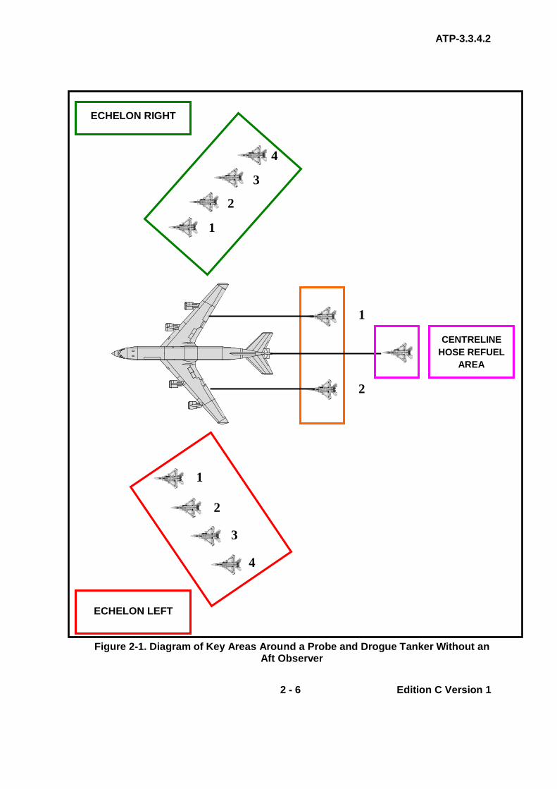
ATP-3.3.4.2
2 - 6 Edition C Version 1
Figure 2-1. Diagram of Key Areas Around a Probe and Drogue Tanker Without an
Aft Observer
2
1
CENTRELINE HOSE REFUEL
AREA
2
1
4
3
ECHELON RIGHT
ECHELON LEFT
2
1
3
4

ATP-3.3.4.2
2 - 7 Edition C Version 1
(2) Tankers With Refuelling Observers. Where the tanker has rearward facing observers or boom operators, the Echelon Left position is behind the wingline of the tanker. See Figure 2-2.
Figure 2-2. Diagram of Key Areas Around Tankers - Boom and Probe and Drogue
with an Aft Observer
ECHELON LEFT
2
1
4
3
ECHELON RIGHT
2
1
CENTRELINE HOSE REFUEL
AREA
WING HOSE REFUEL
AREA
2
1
4 3

ATP-3.3.4.2
2 - 8 Edition C Version 1
b. Joining Multi-Tanker Formations. Multi-tanker formations are to be in
Echelon Right formation during receiver joins. Receivers are normally to join on the left of a multi-tanker formation, or to the left of their assigned tanker once visual with the complete formation.
2.6. REFUELLING – PROBE AND DROGUE
a. Join – Echelon Left Position. Receivers arrive from tanker’s left side and form up in the Echelon Left position as described in para. 2.5. See Figures 2-3A, 2-3B and Figure 2-2 as appropriate to the tanker.
b. Receiver Sequence. To ensure safe operations, the tanker will direct
receivers to the formation position that they are to adopt. Furthermore, the tanker will direct when receiver aircraft are to reposition. Receiver aircraft are to move sequentially from Echelon Left position to the astern position on command from the tanker; this command may be given by radio or by using the standard procedural signals in EMCON conditions. See Figure 2-3 for illustrations of controlled receiver flow around the tanker.
c. Simultaneous Movement of Receivers- Repositioning Receivers. Up
to two receivers may be directed to move simultaneously from the Echelon Left position to behind the hoses. Similarly, both aircraft behind the hoses may be directed to move simultaneously from this position to the Echelon Right position. See Figure 2-3 for illustrations of controlled receiver flow around the tanker. Until directed by the tanker, all other aircraft should remain steady in their allocated formation position.
d. Collision Avoidance. Receivers are responsible for ensuring that the
airspace they are moving into is clear of other aircraft. In addition, moving receivers are mutually responsible for ensuring that they do not collide with the other repositioning aircraft.
e. Receiver(s) on Tanker with 2 Wing Refuelling Stations
(1) One Receiver on Tanker with 2 Wing Refuelling Stations. When the tanker has 2 wing refuelling stations and both are available, the receiver moves to the right hand refuelling position.
(2) Two Receivers on Tanker with 2 Wing Refuelling Stations. If
there is more than one receiver and both refuelling stations are vacant, the first receiver moves behind the right hand hose into the astern position, and the second receiver moves in turn behind the left hand hose into the astern position. See Figures 2-3C and 2-3D.

ATP-3.3.4.2
2 - 9 Edition C Version 1
(3) Receivers Waiting on the Tanker Wing. Until directed by the tanker, all other aircraft should remain steady in their allocated formation position.
f. Receiver(s) on Tanker with One Wing Refuelling Station or
Centreline Station
(1) Movement of Receivers. When the tanker has one wing refuelling station or a single centreline hose, only one receiver will be directed to move in turn to cycle from the Echelon Left position to behind the available hose.
(2) Receivers Waiting on the Tanker Wing. Until directed by the
tanker, all other aircraft should remain steady in their allocated formation position.
g. Clear for Contact and Remaining in Contact
(1) Individual Clearance to Contact. Normally, the tanker is only
able to safely monitor one receiver at a time. Consequently, receivers will be cleared (verbally and/or by light signals) to make contact one at a time. Where the tanker is able to monitor both receivers, simultaneous contacts may be approved.
(2) Remaining in Contact. Because of the potential to cause the
tanker to yaw slightly if one receiver disconnects from a wing hose, receivers should remain in contact until cleared to disconnect by the tanker. See Figure 2-3E.
h. Disconnect. Normally, when both wing hoses are occupied, the tanker
will instruct receivers to disconnect simultaneously. However, the tanker may order individual disconnects either to maximise hose efficiency or because of disparate receiver fuel states.
(1) Other Considerations for Disconnecting. Refer to Chapter 2
Section IV para. 2.28.e. for other safety considerations associated with receiver disconnects.
i. Change Hose Procedure. It is important to move only one receiver at a
time when cycling/changing the receivers behind hoses. To cycle 2 receivers between wing hoses, the tanker is to:
(1) Order one receiver to the Echelon Left or Right position. (2) With this achieved, the second receiver may be cleared to the
astern position behind the vacant hose. (3) On completion of this manoeuvre, the first receiver may be
cleared to the astern position behind its new hose.
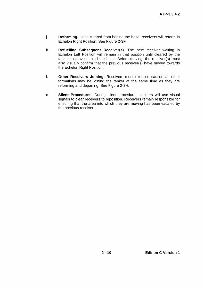
ATP-3.3.4.2
2 - 10 Edition C Version 1
j. Reforming. Once cleared from behind the hose, receivers will reform in
Echelon Right Position. See Figure 2-3F.
k. Refuelling Subsequent Receiver(s). The next receiver waiting in Echelon Left Position will remain in that position until cleared by the tanker to move behind the hose. Before moving, the receiver(s) must also visually confirm that the previous receiver(s) have moved towards the Echelon Right Position.
l. Other Receivers Joining. Receivers must exercise caution as other
formations may be joining the tanker at the same time as they are reforming and departing. See Figure 2-3H.
m. Silent Procedures. During silent procedures, tankers will use visual
signals to clear receivers to reposition. Receivers remain responsible for ensuring that the area into which they are moving has been vacated by the previous receiver.
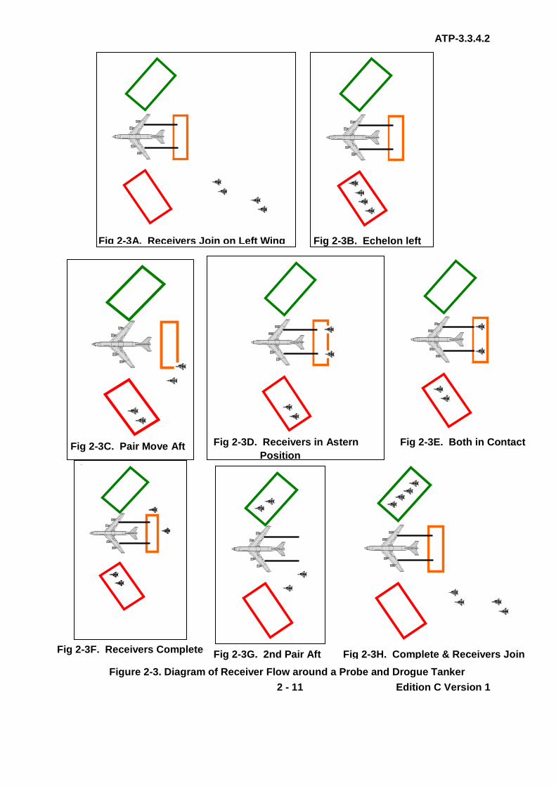
ATP-3.3.4.2
2 - 11 Edition C Version 1
Fig 2-3A. Receivers Join on Left Wing Fig 2-3B. Echelon left
Fig 2-3C. Pair Move Aft Fig 2-3D. Receivers in Astern Position
Fig 2-3E. Both in Contact
Fig 2-3F. Receivers Complete Fig 2-3G. 2nd Pair Aft Fig 2-3H. Complete & Receivers Join Figure 2-3. Diagram of Receiver Flow around a Probe and Drogue Tanker

ATP-3.3.4.2
2 - 12 Edition C Version 1
2.7. JOINING - BOOM
a. Join - Single Tanker – Echelon Left Position. Receivers arrive from tanker’s left side, unless the lead tanker directs otherwise, and form up in the Echelon Left position. The Echelon Left position is behind the wingline of the tanker. See Figure 2-4 and Figure 2-5A.
(1) First Boom Receiver. The boom operator has a good rear view
of the receiver and is able to give detailed commentary and advice to both the receiver and the tanker. If cleared by the tanker, the first receiver of a formation may join directly behind the boom. The receiver visually must confirm that no AAR is in progress and that the boom is lowered. See Figures 2-5B.
(2) Remainder of Formation. All other members of the formation
should form up in the Echelon Left position. See Figures 2-5A and B.
b. Joining Multi Tanker Formations. Multi-tanker formations are to be in
Echelon Right formation during receiver joins. Receivers are normally to join on the left of a multi-tanker formation, or to the left of their assigned tanker once visual with the complete formation. See Figures 2-5A and 2-5B.
2.8. REFUELLING – BOOM TANKERS
a. Join - Single Tanker – Echelon Left Position. Receivers arrive from tanker’s left side, unless the lead tanker directs otherwise, and form up in the Echelon Left position. The Echelon Left position is behind the wingline of the tanker. See Figure 2-4.
b. Receiver Sequence. To ensure safe operations, the tanker will direct
receivers to the formation position that they are to adopt, i.e. the Echelon Left, refuelling or Echelon Right. Furthermore, the tanker will direct when receiver aircraft are to reposition, and then only one aircraft at a time is to be changing formation position; all other aircraft should remain steady in the formation position allocated by the tanker; this command may be given by radio or by using the standard procedural signals in EMCON conditions. See Figure 2-5 for illustrations of controlled receiver flow around the tanker.
c. Collision Avoidance. Receivers are responsible for ensuring that the
airspace they are moving into is clear of other aircraft. In addition, moving receivers are mutually responsible for ensuring that they do not collide with other repositioning aircraft.
ATP-3.3.4.2
2 - 13 Edition C Version 1
d. Boom Signals. The standard signal given by the boom operator to clear the receiver to the astern position is lowering the boom. Refer to Chapter 2 Annex 2Q, Table 2Q-3.
e. Receiver Flow – Single Tanker
(1) One Tanker and One Receiver. The standard flow for boom
AAR operations between one tanker and one receiver is for the receiver to join directly behind the boom, only if the receiver has visually confirmed that no AAR is in progress and that the boom is lowered.
(2) One Tanker and More Than One Receiver. With the exception
of non-bomber heavy receivers that flow from right to left, for two or more receivers the standard flow is left to right. This standard may only be adjusted when airspace, ATO, or SPINS make flowing from left to right impossible.
f. Refuelling First Receiver. The first receiver is refuelled and, when
complete moves to the Echelon Right position on the right wing. See Figures 2-5C and 2-5D.
(1) Receiver/Tanker Formation. Once in position, the receiver pilot
flies close formation with the tanker, although this can be complicated by wake turbulence.
(2) Boom/Receiver Mating. The boom is unlatched from its stowed
position and “flown” towards the receiver by the boom operator using the attached wings. The telescoping section is then hydraulically extended until the nozzle fits into the receiver's receptacle.
(3) Fuel Flow. Following connection of the boom nozzle with the
receiver’s receptacle, an electrical signal is passed between the boom and receiver, hydraulically opening valves. At this point, the tanker activates pumps to drive fuel through the boom, and into the receiver.
(4) Indicator Lights. Once the two aircraft are mated, additional
lights (pilot director lights (PDLs)) on the tanker, activated by sensing switches in the boom, illuminate if the receiver flies too low or too high, or too near or too far away.
g. Refuelling Complete. When fuelling is complete, the valves are closed
and the boom is automatically or manually retracted.
h. Reforming. Once cleared from behind the boom, receivers will reform in Echelon Right Position. See Figure 2-5D.

ATP-3.3.4.2
2 - 14 Edition C Version 1
i. Refuelling Subsequent Receivers. The next receiver(s) waiting in the Echelon Left Position will remain in that position until cleared by the tanker to move. Once the refuelled receiver is clear of the boom and moving towards the Echelon Right position, the next receiver in the sequence will be directed to the astern position and then complete the refuelling sequence discussed above. Before moving, the receiver must also visually confirm that the previous receiver has moved towards the Echelon Right Position. See Figure 2-5E.
j. Other Receivers Joining. Receivers must exercise caution as other
formations may be joining the tanker at the same time as they are reforming and departing. See Figures 2-5F and 2-5G.
k. Silent Procedures. During silent procedures, tankers will use visual
signals to clear receivers to reposition. See Chapter 2 Annex 2Q, Table 2Q-3. Receivers should comply with the controlled formation changes detailed above.

ATP-3.3.4.2
2 - 15 Edition C Version 1
Figure 2-4. Diagram of Key Areas Around a Boom Tanker
ECHELON LEFT
2
4
3
1 BOOM
REFUELLING
ECHELON RIGHT
2
1
3
4

ATP-3.3.4.2
2 - 16 Edition C Version 1
Fig 2-5B. Echelon Left
Fig 2-5C. Receiver Refuels Fig 2-5D. 1st Receiver to Echelon Right
Fig 2-5E. 2nd Receiver Refuels
Fig 2-5A. Join – No 1 to Boom, Remainder to Left Wing

ATP-3.3.4.2
2 - 17 Edition C Version 1
Fig 2-5G. Formation Departs Fig 2-5F. Receivers Joins
Figure 2-5. Diagram of Receiver Flow Around a Boom Tanker 2.9. REFUELLING – BOOM DROGUE ADAPTOR (BDA) Chapter 1, Section III, para. 1.16. describes how the boom is modified through the BDA to allow probe receiver aircraft to take on fuel. In order to achieve a successful transfer of fuel, the tanker and receiver must comply with the following:
a. The tanker flies straight and level, and the drogue is allowed to trail out behind and below it.
b. Probe equipped receivers should adopt formation positions appropriate
to a tanker with an observer in the rear of the tanker (Figures 2-2 and 2-4).
c. The drogue can be flown by the boom operator but the receiver must fly
the probe directly into the basket to make contact. d. The boom operator holds the BDA as motionless as possible. e. The receiver must make contact with the drogue and then move forward
and offset to one side. f. After the receiver states "contact" the boom operator triggers contact
which allows the tanker pilot to start the AAR pumps and offload fuel. g. The receiver maintains position during refuelling, keeping an eye on the
hose to make sure he remains in a suitable position.

ATP-3.3.4.2
2 - 18 Edition C Version 1
h. When fuelling is complete, the receiver decelerates firmly enough to extract the probe out of the basket. The line of rearward movement should straighten the hose and place the probe along the same longitudinal access as the boom and hose, thereby minimising lateral loads on the probe.
2.10. LEAVING
a. Boom Fighters and Probe and Drogue Receivers (Fighter and Heavy Aircraft). Once refuelling is complete, receivers will be cleared to the Echelon Right position. If there are two or more receivers, they should reform using Echelon Right formation, moving sequentially outboard of the tanker with the first receiver remaining closest to the tanker’s wing. From this position, they leave the tanker either level with the tanker or climbing.
(1) Vertical Separation. Normally, receivers must not descend from
a tanker formation unless co-ordinated with an ATC or other controlling unit as other receivers are likely to be joining the tanker from below.
b. Heavy Receivers - Boom. Normally, on completion of AAR, the
tanker(s) will climb to the top of the AAR block and the receiver will descend to the bottom of the AAR block. While obtaining the tanker post AAR report, the receiver is to manoeuvre to a position that ensures safe separation from the tanker(s). Thereafter, the tanker is to return to the designated ATC or control frequency.
(1) Receivers Required to Climb. Where receiver(s) are required to
accelerate and climb on the refuelling heading, the receiver(s) will manoeuvre either left or right (with minimum of 1 nm separation) of the tanker(s) prior to accelerating and climbing. This will preclude the departing receiver’s jet wash from causing injury to personnel on or damage to the remaining tanker(s).
2.11. TYPES OF RV
a. RV Alpha (Anchor RV). This is a procedure directed by a radar control station, whether ground based, seaborne, or airborne (AEW); details are at Chapter 2 Annex 2A.
b. RV Bravo. This is a heading based procedure which utilises air-to-air
equipment of both tanker and receiver. The tanker controls the procedure; details are at Chapter 2 Annex 2B.
c. RV Charlie. This is a heading based procedure similar to the RV Bravo
which allows receivers with an Airborne Intercept (AI) radar to control the procedure once positive AI radar contact is established; details are at Chapter 2 Annex 2C.

ATP-3.3.4.2
2 - 19 Edition C Version 1
d. RV Delta (Point Parallel). This procedure requires the receiver to
maintain an agreed track and the tanker to maintain the reciprocal track, offset a pre-determined distance; details are at Chapter 2 Annex 2D.
e. RV Echo (Timing). This procedure is intended for use in support of a
combat air patrol (CAP); particularly during periods of EMCON constraints; details are at Chapter 2 Annex 2E
f. RV Foxtrot (Sequenced). This procedure is normally used when the
tanker and receiver operate from the same base; details of the accompanied/buddy climb and tailchase departure are at Chapter 2 Annex 2F.
g. RV Golf (En-route). This procedure facilitates join up on a common
track to make good a scheduled time. The receivers may have departed either from the same or different bases. There are a number of enroute RVs; details are at Chapter 2 Annex 2G.
2.12. EQUIPMENT UNSERVICEABILITIES In the event of equipment unserviceabilities which prevent the implementation of a RV procedure according to plan, the tanker is to make good the pre-arranged time at the control point and orbit left until a join-up is achieved, or, at the tanker commander’s discretion, the attempt to RV is abandoned.

ATP-3.3.4.2
2 - 20 Edition C Version 1
INTENTIONALLY BLANK

ANNEX 2A to ATP-3.3.4.2
2A - 1 Edition C Version 1
CHAPTER 2 FIXED WING PROCEDURES ANNEX 2A RV ALPHA (ANCHOR RV)
2.A.1. INTRODUCTION The RV Alpha (Anchor) procedure is a RV carried out under the control of a radar station on the ground, in the air or on-board ship. The RV Alpha is normally used to vector receivers to tankers operating on an AARA/anchor area but may be used as required in any situation. However, with the agreement of the tanker, the controller may give the tanker alterations of heading to effect a quicker join-up. 2.A.2. PROCEDURE The essential requirement for a RV Alpha is positive control by the radar controller to bring the receiver to an ideal position of 1 nm behind and 1000 ft below the tanker.
a. Track Requirements. The radar controller will either anchor the tanker or provide headings for it to fly.
b. Tanker Responsibilities. The tanker(s) is(are) to:
(1) Fly an anchor orbit unless directed otherwise by the radar
controller. (2) Be at the base AAR altitude. (3) Normally, fly the turns at either 15 or 25 AOB.
c. Receiver Responsibilities. Receiver(s) are to:
(1) FL/Altitude/Height. When directed by the controlling agency, be
established at 1,000 ft below the assigned base air refuelling altitude.
(2) Heading. Fly headings as directed by the controlling agency. (3) Receiver Takes Control of RV. Complete the RV using organic
AI radar once radar contact with the tanker is established and call: “(Callsign) Judy”
(4) Receiver Visual with Tanker. When visual with the tanker and
EMCON procedures permit the use of radios, the receiver calls:
“(Callsign) VISUAL”
(5) and is then cleared by the tanker to join (on the left unless directed otherwise by the tanker).

ANNEX 2A to ATP-3.3.4.2
2A - 2 Edition C Version 1
d. Communication Procedures. Whilst on station, the tanker will monitor
the published AAR frequency. When the controlling agency initiates the receiver RV, it will ensure that the receiver(s) confirm their FL/altitude/height, A/A TACAN (channel), Mode 3 and armament state to the tanker.
(1) In EMCON 1, the receiver(s) should not close inside 1 nm until
radio contact is established with the tanker. (2) If either the tanker or receiver(s) is not at its briefed
FL/altitude/height an additional radio call is to be made when established at its nominated FL/altitude/height.
(3) During EMCON 2, radio calls will not be made unless they are
necessary to ensure safe vertical separation.
e. Vertical Separation. The RV vertical separation is to be maintained until 1nm from the tanker(s) and visual contact is established. The receiver(s) will then commence a gradual climb to the astern (boom) or Echelon Left position (drogue). If the tanker(s) is not acquired visually by 1 nm, use the procedures described in Chapter 2, Section I, para. 2.2.d.
f. Navigation Responsibilities During AAR. Unless the controlling
agency is vectoring the tanker, navigation is the tanker’s responsibility from the astern position (boom) or Echelon Left position (drogue) until the receiver(s) depart the tanker. Nevertheless, receivers should monitor their navigation systems to ensure situational awareness.
2.A.3. CONTROL Where a radar station provides advisory information, as distinct from control, one of the other types of RV should be planned. In this case, the information passed by the radar station may be used to supplement the use of airborne aids. 2.A.4. ANCHOR PATTERN
a. The refuelling anchor pattern is a left-hand racetrack with legs separated by as little as 7 nm for smaller, slower tankers such as the KC-130 and as much as 20 nm for larger, faster tankers. The standard leg length for this pattern is 50 nm, as shown in Figure 2A-1.
b. The location of the pattern is determined by the anchor point and the
orientation of the inbound course.
c. Single tankers or tanker formations may be used in the anchor. Routinely, single tankers will be separated by 4000 ft; tanker formations will be separated by 4000 ft between the highest aircraft in the lower formation and the lead aircraft of the next higher formation. (The actual

ANNEX 2A to ATP-3.3.4.2
2A - 3 Edition C Version 1
vertical separation between tanker formations will be briefed in the SPINS or pre-flight formation brief. Normally, 3000 ft should be considered the minimum for safe vertical separation between multiple tanker formations).
d. Anchor AAR tracks requiring frequent turns should be flown in trail or
offset trail (approximately 20° echelon, as described in Chapter 2 Annex 2H).
Figure 2A-1. Anchor Pattern 2.A.5. ALTERNATIVE ANCHOR PATTERN In the event that a radar control unit is not available to control an anchor RV, an alternative anchor pattern is to be flown. This pattern is shown at Figure 2A-2 and the RV procedure is described in Chapter 2 Annex 2D.
Figure 2A-2. Alternate Anchor Pattern
7 - 20 NM
ANCHOR POINT
ARIP

ANNEX 2A to ATP-3.3.4.2
2A - 4 Edition C Version 1
INTENTIONALLY BLANK

ANNEX 2B to ATP-3.3.4.2
2B - 1 Edition C Version 1
CHAPTER 2 FIXED WING PROCEDURES ANNEX 2B RV BRAVO
2.B.1. INTRODUCTION The RV Bravo is a heading based procedure that utilises air to air equipment of both tanker and receiver; it is ideally suited for situations where accuracy of the navigation equipment of the tanker or receiver is in doubt or degraded. It has a further advantage in that it does not require a prebriefed AAR track. However, for briefed tasks an ARIP, the receiver’s inbound track and a RV control time are normally designated. This procedure caters for non-AI radar equipped receivers; it is also suitable for large or battle-damaged receivers, because the tanker performs all turns during the procedure. As this procedure is heading rather than track based, it may not be suited to a busy ATC environment. 2.B.2. PROCEDURE
a. Track Requirements. A reciprocal head-on approach without lateral displacement is set up. To give sufficient time to correct any heading error, a minimum initial head-on separation of 100 nm is desirable. See Figure 2B-1.
b. Navigation to the ARIP. For maximum flexibility, the tanker should plan
to have time in hand and a timing racetrack should be set up to the left at a convenient position up-track from the ARCP. Both aircraft navigate to make good the ARIP at the ARCT.
c. Receiver and Tanker Airspeeds
(1) The tanker flies at the indicated refuel speed for the receiver.
This speed is available in the appropriate National SRD, through the SPINS or arranged between the tanker and receiver on the ground or in the air prior to AAR.
(2) The tanker translates the indicated refuel speed into TAS for the
RV altitude (Chapter 2 Annex 2D, Tables 2D-1 and 2D-2), applies it to the appropriate AOB table (Table 2B-1) and calculates the turn range.
(3) The receiver should normally fly the procedure at the tanker’s
speed (KIAS) plus 20 kts.

ANNEX 2B to ATP-3.3.4.2
2B - 2 Edition C Version 1
d. Transmission for Direction Finding (DF)
(1) After the RV Initial Call has been made, the tanker crew is to call ‘Transmit for DF’ or use any other suitable equipment to ascertain relative positions.
(2) The tanker is to control the heading of the receiver to establish it
on a reciprocal heading.
Example:
(a) Tanker and receiver established on heading 090º and 270º respectively.
(b) The tanker pilot calls “TRANSMIT FOR DF” and then
establishes that the relative bearing of the receiver is 20º right of the tanker’s nose.
(c) He then calls for the receiver aircraft to turn 10º right onto
280º and changes his own heading to 100º.
(3) As the RV progresses, further 10 second carrier wave transmissions are to be requested to refine the head-on approach using the technique described in paras. 0202B.d (1) and (2).
e. Tanker Turn Range. When the appropriate turn range is reached (see
Table 2B-1) the tanker is to turn to the left through 225°.
f. Tanker Reversal onto Receiver’s Track
(1) On roll-out, the tanker is to take a bearing on the receiver using DF or other suitable equipment, obtain a range using A/A TACAN and start a stop-watch.
(2) These figures are plotted on the chart at Figure 2B-2 to obtain a
time to run to the final turn onto the receiver’s heading.
(a) Ideally, the receiver’s relative bearing from the tanker should be 285° and adjustments to the tanker/receiver speeds are not required.
(b) However, if the bearing is other than 285°, using Figure
2B-2 the tanker must adjust speed to re-establish the ideal RV geometry.

ANNEX 2B to ATP-3.3.4.2
2B - 3 Edition C Version 1
2.B.3. CONTROL The RV Bravo is to be controlled throughout by the tanker unless, because of equipment unserviceabilities, the tanker makes a positive handover of control to the receiver. Should its equipment be unserviceable, the tanker, without relinquishing control, is to request the receiver to use its own equipment to establish the head-on approach. The receiver is to advise the tanker of all alterations of heading. Range information may be obtained from a ground radar unit.

ANNEX 2B to ATP-3.3.4.2
2B - 4 Edition C Version 1
Figure 2B-1. Diagram of RV Bravo NOTES: 1. A minimum initial head-on separation of 100 nm (A-B) should be planned. 2. C-D = turn range. 3. The tanker racetrack is shown in an ideal position but it may be planned
elsewhere as required.
ARIP

ANNEX 2B to ATP-3.3.4.2
2B - 5 Edition C Version 1
Table 2B-1. RV Bravo Turn Range
Tanker 25° AOB Tanker 15° AOB
Tanker Speed (TAS)
Turn Range (NM)
Tanker Speed (TAS)
Turn Range (NM)
230 8.4 180 9.2
240 9.0 190 10.0
250 9.6 200 10.9
260 10.3 210 11.8
270 11.0 220 12.8
280 11.7 230 13.9
290 12.4 240 14.9
300 13.2 250 16.0
310 14.0 260 17.2
320 14.8 270 18.4
330 15.6 280 19.6
340 16.5 290 20.9
350 17.3 300 22.2
360 18.2
370 19.2
380 20.1
390 21.1
400 22.1
410 23.1
420 24.2
430 25.2
440 26.3
450 27.5
460 28.6
470 29.8
480 31.0

ANNEX 2B to ATP-3.3.4.2
2B - 6 Edition C Version 1
490 32.2
500 33.4
Figure 2B-2. RV Bravo Correction Chart
ASSUMPTIONS
1. Tanker 25ºAOB 2. Tanker rolls out 1 nm ahead of receiver 3. Receiver IAS 20 kts above tanker 4. ISA 5. Tanker in the turn at range specified

ANNEX 2B to ATP-3.3.4.2
2B - 7 Edition C Version 1
NOTES: 1. When tanker is on a heading of 45° less than the receivers, obtain relative
bearing and A/A TACAN range and start stop-watch. 2. Adjust tanker speed, based on left hand speed scale, if relative bearing is other
than 285°. 3. Plot receiver’s position on chart and determine tanker’s distance/time to the final
turn. 4. Tanker turns onto receiver’s heading at appropriate distance/time. 5. If A/A Tacan range decreases and then starts to increase again, ignore timing
and turn immediately on to receiver’s heading then carry out DF to resolve relative position.

ANNEX 2B to ATP-3.3.4.2
2B - 8 Edition C Version 1
INTENTIONALLY BLANK
ANNEX 2C to ATP-3.3.4.2
2C - 1 Edition C Version 1
CHAPTER 2 FIXED WING PROCEDURES ANNEX 2C RV CHARLIE
2.C.1. INTRODUCTION The RV Charlie is a heading based procedure (similar to the RV Bravo) that allows receivers with an AI radar to control the RV once positive AI radar contact is established. It is thus ideally suited when accuracy of tanker navigation equipment is in doubt or degraded. It does not require a pre-briefed AAR track. However, for briefed tasks an ARIP, the receiver’s inbound track and an ARCT are designated. It requires the receiver to use an AI radar to complete the RV. As this procedure is heading rather than track based, it may not be suited to a busy ATC environment. 2.C.2. PROCEDURE
a. Track Requirements. A reciprocal head-on approach with no lateral displacement is set up. To give sufficient time to correct any heading error, a minimum initial head-on separation of 100 nm is desirable; see Figure 2C-1.
b. Navigation to the ARIP. For maximum flexibility, the tanker should plan
to have time in hand; a left hand timing racetrack may be set up at a convenient position up-track from the ARIP, if required. Both aircraft navigate to make good the ARIP at the ARCT.
c. Receiver and Tanker Airspeeds
(1) The tanker flies at the indicated refuel speed for the receiver.
This speed is available in the appropriate National SRD, through the SPINS or arranged between the tanker and receiver on the ground or in the air prior to AAR.
(2) The tanker translates the indicated refuel speed into TAS for the
RV altitude (Chapter 2 Annex 2D, Tables 2D-1 and 2D-2), applies it to the appropriate AOB table (Table 2C-1) and calculates the turn range dependent on drift.
(3) The receiver should normally fly the procedure at the tanker’s
speed (KIAS) plus 20 kts.
d. Transmission for Direction Finding (DF)
(1) After the RV Initial Call has been made, the pilot in control is to call ‘Transmit for DF’ or use any other suitable equipment to ascertain relative positions.

ANNEX 2C to ATP-3.3.4.2
2C - 2 Edition C Version 1
(2) The controlling aircraft is to establish the other aircraft on a reciprocal heading.
Example:
(a) Tanker and receiver established on heading 360º and
180º respectively. (b) The pilot in control calls “Transmit for DF’ and then
establishes that the relative bearing of the tanker is 20º left of the receiver’s nose.
(c) He then calls for the tanker to turn 10º left onto 350º and
changes his own heading to 170º.
(3) As the RV progresses, further 10 second carrier wave transmissions are to be requested to refine the head-on approach using the technique described in paras. 0202C.d(1) and (2).
(4) Separation between aircraft is to be measured using A/A TACAN
or AI equipment. (5) The turn range must be passed to and acknowledged by the
receiver.
e. Tanker and Receiver Turn Range
(1) When the turn range is reached, see Table 2C-1, the tanker is to turn left through 180o
and the receiver(s) is to turn right 45o using
45o AOB and roll out wings level.
(2) When required, the receiver(s) is to commence a left turn to roll-
out onto the tanker’s heading. (3) If visual at any time during the RV, the receiver(s) is to adjust
flight path as necessary to expedite the RV. 2.C.3. CONTROL
a. Initial Control. The initial control of RV Charlie (achieving and maintaining the head-on approach) is usually accomplished by the tanker.

ANNEX 2C to ATP-3.3.4.2
2C - 3 Edition C Version 1
b. Receiver Control. When the receiver has closed to effective AI range and is able to complete the procedure unassisted, the receiver is to call ‘Judy’ and then take control. On occasions it may be more appropriate for suitably equipped receivers to control the procedure throughout; however, it is important to establish clearly which aircraft is in control. Therefore, as a standard procedure, the tanker controls the RV, unless management for the whole RV is positively handed to the receiver.
c. Turn to ARCP. Each aircraft is to turn towards the ARCP at the turn
range. d. Failure to Achieve AI Contact. In the event of the receiver not gaining
AI contact, this procedure can revert to an RV Bravo (Chapter 2 Annex 2B) as long as there is adequate split range.

ANNEX 2C to ATP-3.3.4.2
2C - 4 Edition C Version 1
Figure 2C-1. Diagram of RV Charlie
NOTES: 1. A minimum initial head-on separation of 100 nm (A-B) should be planned. 2. C-D = turn range. 3. The tanker racetrack is shown in an ideal position but it may be planned
elsewhere as required.
ARIP
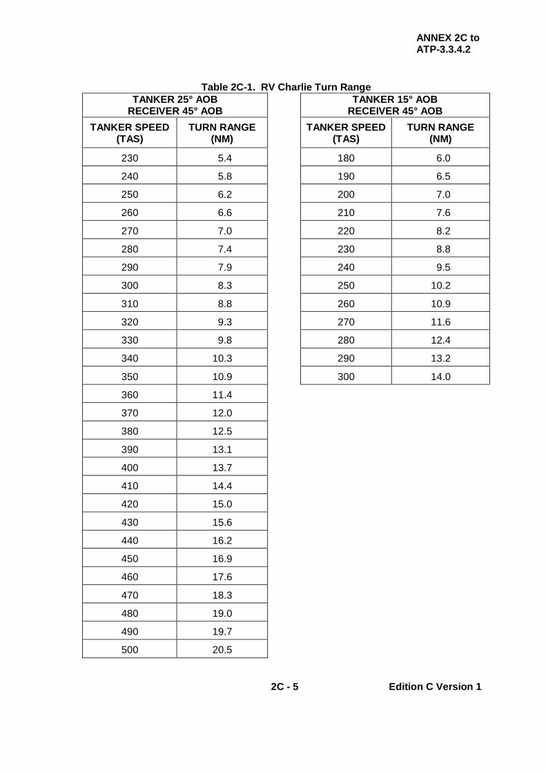
ANNEX 2C to ATP-3.3.4.2
2C - 5 Edition C Version 1
Table 2C-1. RV Charlie Turn Range TANKER 25° AOB
RECEIVER 45° AOB TANKER 15° AOB
RECEIVER 45° AOB TANKER SPEED
(TAS) TURN RANGE
(NM) TANKER SPEED
(TAS) TURN RANGE
(NM)
230 5.4 180 6.0
240 5.8 190 6.5
250 6.2 200 7.0
260 6.6 210 7.6
270 7.0 220 8.2
280 7.4 230 8.8
290 7.9 240 9.5
300 8.3 250 10.2
310 8.8 260 10.9
320 9.3 270 11.6
330 9.8 280 12.4
340 10.3 290 13.2
350 10.9 300 14.0
360 11.4
370 12.0
380 12.5
390 13.1
400 13.7
410 14.4
420 15.0
430 15.6
440 16.2
450 16.9
460 17.6
470 18.3
480 19.0
490 19.7
500 20.5

ANNEX 2C to ATP-3.3.4.2
2C - 6 Edition C Version 1
INTENTIONALLY BLANK

ANNEX 2D to ATP-3.3.4.2
2D - 1 Edition C Version 1
CHAPTER 2 FIXED WING PROCEDURES ANNEX 2D RV DELTA (POINT PARALLEL)
2.D.1. INTRODUCTION The RV Delta (Point Parallel) procedure requires the receiver to maintain an agreed track and the tanker to maintain the reciprocal track, offset a pre-determined distance; see Figure 2D-1. 2.D.2. PROCEDURE
a. Track Requirements. A common track of at least 70 nm is usually the minimum requirement for the RV and consists of a straight line between the ARIP and the ARCP.
b. Receiver and Tanker Airspeeds. Two methods exist to determine
when the tanker initiates its final turn onto the receiver’s heading.
(1) Option 1 - Tanker Airspeed Known to Receiver
(a) RV Speed - Tanker. The tanker flies at the indicated refuel speed for the receiver. This speed is available in the appropriate National SRD, through SPINS or pre-arranged between the tanker and receiver on the ground or in the air prior to AAR.
(b) Turn Range. The tanker translates the indicated refuel
speed into TAS (Table 2D-1 or Table 2D-2), applies it to the appropriate AOB table (Table 2D-3 or Table 2D-4) and calculates the turn range dependent on drift.
(c) RV Speed – Receiver. The receiver should normally fly
the procedure at the tanker’s speed (KIAS) plus 20 kts. (d) Turn Range and Offset Calculation. The worksheet at
Table 2D-5 provides a step by step approach to calculating the tanker turn range and offset.
(e) Receiver Roll Out Range. The data in Table 2D-3 or
Table 2D-4 should result in the tanker rolling out with the receiver 1 nm behind the tanker.

ANNEX 2D to ATP-3.3.4.2
2D - 2 Edition C Version 1
(2) Option 2 - Receiver Airspeed Known to Tanker (Normal USAF Procedure) (a) RV Speed – Receiver. The tanker extracts the receiver
indicated RV speed from the appropriate National SRD, SPINS or as pre-arranged between the tanker and receiver on the ground or in the air prior to AAR.
(b) RV Closure Speed. The tanker translates the receiver’s
indicated refuel speed into TAS using Table 2D-1 or Table 2D-2 and adds it to the tanker’s TAS to calculate the RV closure speed.
(c) Turn Range. Entering the Table 2D-6 or Table 2D-8 with
the RV closure speed will provide the tanker’s turn range, dependent on AOB.
(d) Anchor Offset. The anchor offset, corrected for drift and
tanker TAS is derived from Table 2D-7 or Table 2D-9, dependent on AOB.
(e) Back-Up Turn Time. Table 2D-11 provides a backup
time to turn based on a known hack range and closure speed.
(f) Turn Range and Offset Calculation. The worksheet at
Table 2D-12 provides a step by step approach to calculating the tanker turn range and offset.
(g) Receiver Roll Out Range. The data in Table 2D-6 or
Table 2D-7 will result in the tanker rolling out with the receiver behind the tanker at 3nm, ½nm or 1nm in front of the tanker, depending on the receiver AAR speed.
(h) Turn Range/Offset Correction - 3 NM Rollout. During
an RV Delta execution, if the actual offset differs from that derived using the instructions in para. 2.D.2.b.(2)(f), use Table 2D-10 to calculate the corrected turn/offset parameters. Using the calculated turn range and offset pairing, enter the chart at column A. Move horizontally through columns B to G to find the actual offset. At the intersection of these variables, identify the revised turn range that will result in a 3 nm RV Delta tanker/receiver rollout.

ANNEX 2D to ATP-3.3.4.2
2D - 3 Edition C Version 1
Example 1: VC10 tanker at FL 230, Tornado F3 receiver at FL220, OAT at tanker altitude minus 35ºC with 15º right drift on the ARIP to ARCP leg.
Tanker RV Speed. From UK National SRD VC10 tanker speed = 280 KIAS Receiver RV Speed. Receiver flies tanker KIAS + 20 kts.
Using the above data and referencing the figures identified in Column C of Table 2D-5, the appropriate interpolated values extracted from the tables will provide both the anchor offset and tanker turn range. A B C D E PARAMETER REFERENCE TANKER RECEIVER
1 ALTITUDE FL230 FL220 2 TANKER RV IAS TANKER
NATIONAL SRD 280
3 RECEIVER RV IAS (=TANKER IAS +20 KTS) 300
4 TANKER RV TAS TABLE 2D-1 or 2 386 5 ACTUAL TEMP -35 6 STD TEMP TABLE 2D-1 -31 7 ACTUAL – STD (Row 4 – Row 5)
(<STD = REDUCE BY 1 kt / ºC) (>STD = INCREASE BY 1 kt / ºC)
- 4
+
8 CORRECTED TAS (Row 3±Row 6) 382
9 ARIP TO ARCP DRIFT 15 L/R 10 TURN RANGE TABLE 2D-3 or 4 23.0 11 OFFSET TABLE 2D-3 or 4 13.4

ANNEX 2D to ATP-3.3.4.2
2D - 4 Edition C Version 1
Example 2: KC-10 Tanker at FL 230, F-16A receiver at FL220, OAT at tanker altitude minus 28ºC with 10º left drift on the ARIP to ARCP leg. Tanker RV Speed. KC-10 tanker speed (varies with aircraft weight) = 275 KIAS. Receiver RV Speed. Figure ZE-4 to Annex ZE provides receiver RV speed of 345 KIAS. Using the above data and referencing the Figures identified in Column C of Table 2D-12, the appropriate interpolated values extracted from the tables will provide both the anchor offset and tanker turn range. Using a few fixed range points and the closure TAS, a backup time to turn can be calculated. These times are extracted from Table 2D-11. A B C D E F PARAMETER REFERENCE TANKER RECEIVER
1 ALTITUDE FL230 FL220
2 RV IAS TANKER NATIONAL SRD 275 345
3 RV TAS TABLE 2D-1 or 2 380 467
4 ACTUAL TEMP
-28
5 STD TEMP TABLE 2D-1 -31
6
ACTUAL – STD (Row 4 – Row 5) (<STD = REDUCE BY 1 kt / ºC) (>STD = INCREASE BY 1 kt / ºC)
-
+ 3
7 CORRECTED TAS (Row 3±Row 6)
383 470
8 CLOSURE TAS (RCVR + TNKR)
853
9 ARIP TO ARCP DRIFT DERIVED FROM
TANKER NAV SYSTEM
10 L/R
10 TURN RANGE TABLE 2D-6 or 8 21.2
11 OFFSET TABLE 2D-7 or 9 7
12 50 MN TIMING BACKUP TABLE 2D-11 1:47 13 30 NM TIMING BACKUP TABLE 2D-11 0:23
ANNEX 2D to ATP-3.3.4.2
2D - 5 Edition C Version 1
c. Tanker Responsibilities. The tanker(s) is(are):
(1) Responsible for directing the rendezvous. (2) To be at the base AAR altitude. (3) May enter the refuelling holding orbit from any direction. (4) To attempt to arrive at least 15 min before the ARCT and,
normally, establish a left-hand holding pattern using the ARCP as an anchor point.
(5) Normally, to fly the straight legs for 2 min duration and fly the
turns at either 15º or 25ºAOB.
d. Receiver Responsibilities. Receiver(s) will:
(1) Be established at 1000 ft below the assigned base AAR altitude when departing the ARIP.
(2) Enter the track via the ARIP and should aim to be at the ARCP at
the ARCT (see Figure 2D-1). (3) Depart from the ARIP and not deviate from the ARIP/ARCP
centreline unless directed to do so by the tanker. (4) Aid the RV, when so equipped, by remaining in electronic contact
on radar, A/A TACAN, TCAS or other means as soon as possible, but no later than 50 nm range or the ARIP, whichever occurs first, until reaching the Echelon Left position (drogue) or astern position (boom).
e. Communication Procedures. Fifteen minutes prior to the ARCT the
tanker and the receiver(s) are to confirm their FL/altitude/height, A/A TACAN (channel), Mode 3, armament state and timing. The receiver(s) should fly down track towards the ARCP with A/A TACAN and radar beacon on (if appropriate) at 1000 ft below the base AAR altitude.
(1) If radio contact between the tanker and receiver has not been
established prior to the ARCT, the tanker will maintain orbit over the ARCP until 10 min after the ARCT, unless otherwise briefed.
(2) If either the tanker or receiver(s) is not at its briefed
FL/altitude/height an additional radio call is to be made when established at its nominated FL/altitude/height.
(3) The tanker must not initiate the turn in front of the receiver(s) until
the receivers confirm that they are level at their assigned FL/altitude/height.

ANNEX 2D to ATP-3.3.4.2
2D - 6 Edition C Version 1
(4) During EMCON 2, radio calls will not be made during the RV
unless they are necessary to ensure safe vertical separation. However, an astern RT call is required to ensure two way contact between the tanker and receiver(s).
f. Initiation of RV by Tanker. The tanker will fly the outbound leg at the
appropriate offset from the common track in a holding pattern, see Tables 2D-3, 2D-4, 2D-6 and 2D-7 as appropriate, until it is determined by A/A TACAN, AI equipment, radar beacon (if equipped) or radio call that the receiver(s) are at the ARIP. At that point, the tanker will either extend the outbound leg or, if inbound to the ARCP, turn to the reciprocal of the receiver’s in-bound track to close with the receiver.
g. Initiation of Tanker’s Final Turn. At the appropriate turn range (slant
range), the tanker initiates a turn to return to the ARIP - ARCP track, inbound to the ARCP. If applicable, in EMCON 1, after turning through 90° the tanker is to call ‘halfway round the turn’. This is the best time to determine if an overrun condition exists and the best time for visual acquisition. If an overrun condition exists, carry out the appropriate actions as described in Chapter 2 Section I, para. 2.4.
h. Vertical Separation. The RV vertical separation is to be maintained until
1 nm of the tanker and visual contact is established. The receiver(s) will then commence a gradual climb to the astern (boom) or Echelon Left position (drogue).
i. Tanker/Receiver Rollout Range. At completion of the turn, receivers
are normally 3 nm (US procedures) or 1 nm (other nations) in trail of the tanker(s).
j. Tanker Speed Adjustment. Tankers adjust to refuelling air speed when
rolled out toward the ARCP. k. Navigation Responsibilities During AAR. Navigation responsibility
from the astern position (boom) or Echelon Left position (drogue) until the receiver(s) depart the tanker is primarily with the tanker, with receivers monitoring their navigation system to ensure situational awareness.
NOTE
RADIO SILENCE MUST BE BROKEN IF THE TANKER OR RECEIVER DETERMINES THAT EITHER THE TANKER OR RECEIVER WILL EXCEED ATC PROTECTED AIRSPACE WHILE MANOEUVRING TO ATTAIN THE OFFSET.
l. Late Arrival of Receivers. In the event that the receiver(s) is(are)
delayed, the tanker is to normally maintains a left-hand holding orbit over the ARCP until 10 min after the ARCT, unless otherwise briefed.

ANNEX 2D to ATP-3.3.4.2
2D - 7 Edition C Version 1
m. RV with Correct Receiver. Tankers must ensure that they do not
attempt to RV with the wrong receiver. Comparing the A/A TACAN DME and the TCAS target distance is an effective method of establishing positive identification. Additionally, to aid the receiver in identifying the tanker, if the tanker does not receive a communication from the receiver by ARCT minus 10 min, the tanker will transmit in the blind giving the information normally given during the RV. The tanker will cross the ARCP at the ARCT and at subsequent intervals of 8 min thereafter until the receiver has cancelled or the tanker must depart or is directed to proceed on its mission.
n. Missed RV Procedures. If contact is not established between the
tanker and receiver, the tanker will arrive at the ARCP at the ARCT. When either aircraft arrives at the ARCP and does not have visual contact with the other, the aircraft will cross the ARCP at the appropriate altitude at the ARCT and at subsequent intervals of 8 min thereafter. While in the orbit, every attempt should be made to establish visual contact with the other aircraft. The length of the delay and the decision as to when to terminate radio silence should be determined during mission planning prior to flight.
2.D.3. OVERTAKE RV DELTA (POINT PARALLEL) This procedure assumes that the tanker’s normal cruising height and speed are higher than that of the receiver. It is similar to the RV Delta (Point Parallel) except the tanker plans to roll out 1 nm behind the receiver(s), see Table 2D-6.
a. ARCP – Receiver. The receiver(s) plans to arrive at the ARCP on time, at the base altitude minus 1000 ft.
b. ARCP-Tanker. The tanker arrives at the ARCP one minute after the
receiver at the base altitude. c. Overtake - Tanker. The tanker then overtakes above the receiver(s) at
the base altitude and slows down to position 1 nm in front of the receiver(s) at the refuelling speed.
d. Climb - Receiver. Once visual with the tanker, the receiver(s) climb(s)
to the tanker’s base altitude. e. RV Control. The tanker maintains control of the overtake RV Delta
(Point Parallel) throughout. f. RT Call – Receiver. The receiver(s) must ensure that correct track,
FL/altitude/height and speed are flown and, during EMCON 1, the tanker is to call ‘turn’ at the turn range.
g. EMCON 3. It is possible to fly this procedure in EMCON 3 but aircraft
must be at the correct FL/altitude/height.

ANNEX 2D to ATP-3.3.4.2
2D - 8 Edition C Version 1
2.D.4. MODIFIED RV DELTA (POINT PARALLEL) (EC-135, E-3, E-4, C-130) A modified point parallel RV is a procedure used to accomplish an RV with an EC-135/E-4 aircraft in a Post-Attack Command and Control System (PACCS) orbit, an E-3 on AWACS patrol, or a C-130 in a special on-station orbit; see Table 2D-5. The following procedures will be used:
a. ARIP. The ARIP will be located at one of the turn points. b. ARCP. The ARCP will be located at the turn point on the opposite
direction track. c. Descent – Receiver. If receiver requirements prevent early descent to
RV altitude, the receiver may descend after passing the ARIP; however, the receiver must not descend until radio contact is established with the tanker and safe lateral separation is confirmed.
d. Orbit – Receiver. The receiver will establish a right-hand orbit 1000 ft
below AAR altitude prior to the tanker's entry into the orbit area. e. Orbit – Tanker. The tanker will be at refuelling altitude upon entering the
orbit area and will establish a standard RV Delta (point parallel) orbit at the ARCP.
f. Departing ARIP – Receiver. The receiver will call departing the ARIP.
The receiver will increase airspeed to closure airspeed during the last half of the turn toward the tanker. After the receiver rolls out from the turn toward the tanker, normal RV Delta (point parallel) procedures will be used.
g. Departing ARIP – Tanker. The tanker in the ARCP orbit will turn toward
(if flying away from) or continue toward the ARCP when the receiver calls departing the ARIP.
h. Turn Towards Receiver – Tanker. Two minutes after the receiver's
ARIP call, the tanker will turn toward the receiver. i. Final Turn – Tanker. At the appropriate turn range (Tables 2D-2, 2D-5
and 2D-6) the tanker will turn inbound to the ARCP and adjust to appropriate air refuelling speed (Refer to tanker’s National SRD) when rolled out toward the ARCP.
j. Post RV Actions. Closure and contact will be normal after the RV. The
refuelling track will follow the PACCS/AWACS/Special Orbit Pattern, remaining within published/briefed orbit boundaries, using no more than 15º AOB during turns.
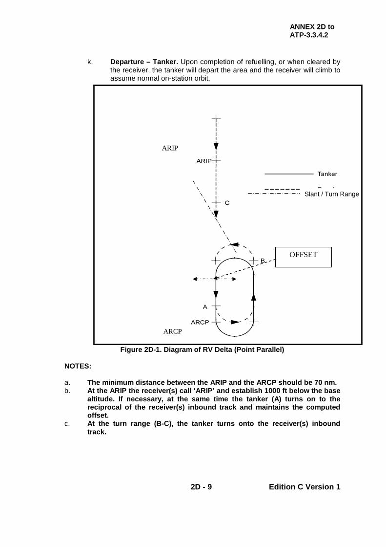
ANNEX 2D to ATP-3.3.4.2
2D - 9 Edition C Version 1
k. Departure – Tanker. Upon completion of refuelling, or when cleared by the receiver, the tanker will depart the area and the receiver will climb to assume normal on-station orbit.
Figure 2D-1. Diagram of RV Delta (Point Parallel) NOTES: a. The minimum distance between the ARIP and the ARCP should be 70 nm. b. At the ARIP the receiver(s) call ‘ARIP’ and establish 1000 ft below the base
altitude. If necessary, at the same time the tanker (A) turns on to the reciprocal of the receiver(s) inbound track and maintains the computed offset.
c. At the turn range (B-C), the tanker turns onto the receiver(s) inbound track.
Slant / Turn Range
OFFSET
ARIP
ARCP

ANNEX 2D to ATP-3.3.4.2
2D - 10 Edition C Version 1
Table 2D-1. KCAS to TAS Conversion
TRUE AIRSPEED TABLE P
RE
SS
UR
E
ALT
ITU
DE
10
00 F
T STD DAY
TEMP
KCAS
200 220 240 250 255 265 275 280 285 290 295 6 +3 215 238 259 272 277 288 299 304 309 314 319 8 -1 222 245 266 279 285 296 307 312 318 323 329
10 -3 230 253 274 287 293 304 315 321 327 332 338 12 -7 237 261 282 296 302 313 324 330 336 341 347 13 -11 240 264 286 300 306 318 329 335 341 346 352 14 -13 244 269 291 305 312 324 335 341 347 352 358 15 -15 248 273 295 310 317 329 340 347 353 358 364 16 -17 254 279 301 315 322 334 345 352 358 363 369 17 -19 258 283 305 319 327 339 350 357 363 368 374 18 -21 262 287 310 324 332 344 355 362 368 373 379 19 -23 266 293 316 330 336 349 361 367 373 378 384 20 -25 269 296 320 334 340 353 366 373 379 384 390 21 -27 273 300 324 338 345 359 372 378 385 391 398 22 -29 276 304 328 342 349 363 376 383 390 396 403 23 -31 280 310 335 349 354 367 380 386 393 400 406 24 -33 284 314 340 354 360 374 388 394 401 407 413 25 -35 289 319 346 361 368 382 396 402 409 415 422 26 -37 294 324 352 366 374 387 402 408 415 422 429 27 -38 301 332 360 374 381 395 410 417 424 431 438 28 -40 307 338 365 380 388 401 415 423 431 438 445 29 -42 313 344 373 388 396 408 423 431 439 446 452 30 -44 318 350 378 395 402 416 430 437 444 451 459 32 -48 330 362 392 407 415 429 443 452 460 469 476 34 -52 342 374 405 419 426 442 456 464 472 481 488 36 -56 352 384 418 432 442 458 472 478 485 494 502
PR
ES
SU
RE
A
LTIT
UD
E
1000
FT STD
DAY TEMP
KCAS
300 305 310 315 320 325 330 335 340 350 6 +3 325 331 336 342 348 354 360 366 372 381 8 -1 335 340 346 352 358 364 370 376 382 391
10 -3 344 349 355 361 367 373 379 385 391 400 12 -7 353 358 364 370 376 382 388 394 400 409 13 -11 358 363 369 375 381 387 393 399 404 414 14 -13 364 369 375 381 387 393 399 405 410 420 15 -15 370 375 381 387 393 399 405 411 416 426 16 -17 375 381 387 393 399 405 411 417 422 432 17 -19 380 386 392 398 404 410 416 422 428 438 18 -21 385 391 397 403 409 415 421 427 434 444 19 -23 390 397 403 409 416 422 428 434 440 451 20 -25 396 403 409 415 422 428 434 440 446 458 21 -27 405 411 417 423 429 435 442 449 455 466 22 -29 410 417 423 430 437 442 449 456 462 473 23 -31 412 419 426 432 439 445 452 459 466 480 24 -33 419 426 433 439 446 453 461 469 476 489 25 -35 428 435 442 449 455 461 468 473 480 493 26 -37 435 442 449 456 462 468 475 482 488 502 27 -38 444 451 458 464 470 477 484 490 496 510 28 -40 452 459 466 473 479 486 493 499 505 518 29 -42 459 466 473 481 487 494 501 508 515 528 30 -44 466 473 480 487 494 501 508 515 523 536 32 -48 484 490 497 504 510 517 525 533 541 554 34 -52 496 503 510 517 523 530 537 545 553 567 36 -56 509 517 524 532 539 547 555 563 570 584
NOTES: 1. For each °C below std day temp subtract 1 knot from std day TAS 2. For each °C above std day temp add 1 knot to std day TAS

ANNEX 2D to ATP-3.3.4.2
2D - 11 Edition C Version 1
Table 2D-2. KIAS to TAS Conversion
TRUE AIRSPEED TABLE
PR
ES
SU
RE
A
LTIT
UD
E
1000
FT KIAS
200 210 225 235 245 250 255 260 270 275 280 285 290 3 212 222 238 249 259 265 269 275 286 291 297 302 307 6 214 224 240 251 261 268 272 278 289 294 298 305 310 9 223 235 251 263 274 279 285 290 302 307 313 318 324
10 227 238 255 267 278 283 289 295 307 312 317 322 328 12 234 245 263 275 286 292 298 303 315 321 327 332 338 14 241 253 271 283 295 301 307 313 325 330 336 342 348 16 249 261 280 292 304 310 316 322 335 341 347 352 359 18 257 269 288 301 314 320 326 332 346 351 357 363 370 20 265 278 298 311 324 330 336 343 356 362 367 374 381 21 270 283 303 316 329 335 342 348 361 367 374 379 387 22 274 288 308 321 334 341 347 355 367 374 380 386 393 23 279 292 313 326 339 347 354 360 372 379 385 392 399 24 283 297 318 332 345 353 359 365 379 384 391 397 404 25 288 302 324 338 351 358 364 371 385 390 397 404 411 26 293 307 329 343 357 363 371 377 390 397 404 410 417 27 298 312 334 348 363 370 376 384 397 404 410 417 424 28 303 318 340 354 369 376 382 390 404 410 417 424 431 29 308 323 345 360 375 385 389 396 411 416 424 431 437 30 313 329 351 366 381 388 395 403 416 424 431 437 445 31 319 335 357 372 387 395 402 410 424 431 437 444 453 32 325 340 364 379 394 401 409 416 431 437 445 452 459 33 331 346 370 385 401 408 416 424 438 445 452 460 466 34 336 352 376 392 407 415 423 431 445 452 460 466 474 35 342 358 382 398 414 422 430 438 454 460 467 474 481
PR
ES
SU
RE
A
LTIT
UD
E
1000
FT KIAS
300 305 310 315 320 325 330 335 340 345 350 355 360 3 318 323 328 334 339 344 350 355 360 366 371 376 381 6 321 326 331 337 342 347 352 358 364 369 374 379 385 9 335 340 346 351 357 362 368 373 379 385 390 395 401
10 340 345 351 356 362 367 373 378 384 390 395 401 406 12 349 355 361 367 372 378 384 390 395 400 406 412 418 14 360 366 372 377 383 389 395 401 407 412 418 424 430 16 371 372 383 389 395 401 407 412 418 424 430 436 442 18 382 388 394 400 407 413 419 425 431 437 443 449 455 20 394 400 406 412 419 425 431 437 444 450 456 462 469 21 400 406 413 418 425 431 438 444 450 456 463 469 475 22 406 413 419 425 432 438 445 452 457 463 470 476 483 23 411 417 425 431 437 444 451 457 464 470 477 483 490 24 417 424 431 437 444 451 458 464 471 477 484 490 497 25 424 431 437 444 450 458 465 472 478 485 491 497 504 26 431 437 444 450 458 465 472 479 486 492 499 505 512 27 437 445 451 459 466 472 479 486 493 500 506 513 520 28 445 452 459 466 474 480 487 494 501 507 514 521 528 29 452 459 466 474 482 488 494 501 508 515 522 529 536 30 459 466 474 482 490 496 502 509 516 523 530 537 544 31 466 474 481 489 497 503 510 517 524 531 538 545 552 32 474 481 489 496 504 511 518 525 532 539 546 553 560 33 481 489 496 504 512 519 526 533 540 547 554 561 568 34 489 497 504 512 520 527 534 541 549 556 563 570 577 35 497 504 512 521 529 535 542 550 558 564 571 578 585
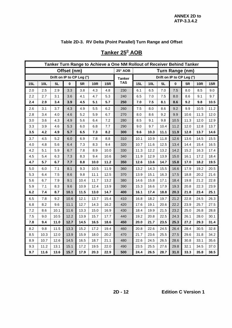
ANNEX 2D to ATP-3.3.4.2
2D - 12 Edition C Version 1
Table 2D-3. RV Delta (Point Parallel) Turn Range and Offset
Tanker 25o AOB
Tanker Turn Range to Achieve a One NM Rollout of Receiver Behind Tanker
Offset (nm) 25° AOB Turn Range (nm) Drift on IP to CP Leg (°) Tanker
TAS Drift on IP to CP Leg (°)
15L 10L 5L 0 5R 10R 15R 15L 10L 5L 0 5R 10R 15R
2.0 2.5 2.9 3.3 3.8 4.3 4.8 230 6.1 6.5 7.0 7.5 8.0 8.5 9.0
2.2 2.7 3.1 3.6 4.1 4.7 5.3 240 6.5 7.0 7.5 8.0 8.6 9.1 9.7 2.4 2.9 3.4 3.9 4.5 5.1 5.7 250 7.0 7.5 8.1 8.6 9.2 9.8 10.5
2.6 3.1 3.7 4.3 4.9 5.5 6.2 260 7.5 8.0 8.6 9.2 9.9 10.5 11.2
2.8 3.4 4.0 4.6 5.2 5.9 6.7 270 8.0 8.6 9.2 9.9 10.6 11.3 12.0
3.0 3.6 4.3 4.9 5.6 6.4 7.2 280 8.5 9.1 9.8 10.5 11.3 12.0 12.9
3.3 3.9 4.6 5.3 6.0 6.8 7.7 290 9.0 9.7 10.4 11.2 12.0 12.8 13.7 3.5 4.2 4.9 5.7 6.5 7.3 8.2 300 9.6 10.3 11.1 11.9 12.8 13.7 14.6
3.7 4.5 5.2 6.0 6.9 7.8 8.8 310 10.1 10.9 11.8 12.6 13.6 14.5 15.5
4.0 4.8 5.6 6.4 7.3 8.3 9.4 320 10.7 11.6 12.5 13.4 14.4 15.4 16.5
4.2 5.1 5.9 6.7 7.8 8.9 10.0 330 11.3 12.2 13.2 14.2 15.2 16.3 17.4
4.5 5.4 6.3 7.3 8.3 9.4 10.6 340 11.9 12.9 13.9 15.0 16.1 17.2 18.4 4.7 5.7 6.7 7.7 8.8 10.0 11.2 350 12.6 13.6 14.7 15.8 17.0 18.2 19.5
5.0 6.0 7.1 8.1 9.3 10.5 11.9 360 13.2 14.3 15.5 16.6 17.9 19.2 20.5
5.3 6.4 7.5 8.6 9.8 11.1 12.5 370 13.9 15.1 16.3 17.5 18.8 20.2 21.6
5.6 6.7 7.9 9.1 10.4 11.7 13.2 380 14.6 15.8 17.1 18.4 19.8 21.2 22.8
5.9 7.1 8.3 9.6 10.9 12.4 13.9 390 15.3 16.6 17.9 19.3 20.8 22.3 23.9 6.2 7.4 8.7 10.1 11.5 13.0 14.7 400 16.1 17.4 18.8 20.3 21.8 23.4 25.1
6.5 7.8 9.2 10.6 12.1 13.7 15.4 410 16.8 18.2 19.7 21.2 22.8 24.5 26.3
6.8 8.2 9.6 11.1 12.7 14.3 16.2 420 17.6 19.1 20.6 22.2 23.9 25.7 27.5
7.2 8.6 10.1 11.6 13.3 15.0 16.9 430 18.4 19.9 21.5 23.2 25.0 26.8 28.8
7.5 9.0 10.5 12.2 13.9 15.7 17.7 440 19.2 20.8 22.5 24.3 26.1 28.0 30.1 7.8 9.4 11.0 12.7 14.5 16.5 18.6 450 20.0 21.7 23.5 25.3 27.2 29.3 31.4
8.2 9.8 11.5 13.3 15.2 17.2 19.4 460 20.8 22.6 24.5 26.4 28.4 30.5 32.8
8.5 10.3 12.0 13.9 15.9 18.0 20.2 470 21.7 23.6 25.5 27.5 29.6 31.8 34.2
8.9 10.7 12.6 14.5 16.5 18.7 21.1 480 22.6 24.5 26.5 28.6 30.8 33.1 35.6
9.3 11.2 13.1 15.1 17.2 19.5 22.0 490 23.5 25.5 27.6 29.8 32.1 34.5 37.0 9.7 11.6 13.6 15.7 17.9 20.3 22.9 500 24.4 26.5 28.7 31.0 33.3 35.8 38.5

ANNEX 2D to ATP-3.3.4.2
2D - 13 Edition C Version 1
Table 2D-4. RV Delta (Point Parallel) Turn Range and Offset
Tanker 15o AOB
Tanker Turn Range to Achieve a One NM Rollout of Receiver Behind Tanker
Offset (nm) 15° AOB Turn Range (nm) Drift on IP to CP LEG (°) Tanker
TAS Drift on IP to CP LEG (°)
15L 10L 5L 0 5R 10R 15R 15L 10L 5L 0 5R 10R 15R
3.6 4.3 5.0 5.8 6.6 7.5 8.4 230 9.9 10.7 11.5 12.3 13.2 14.1 15.1
3.9 4.7 5.5 6.3 7.2 8.1 9.2 240 10.7 11.5 12.4 13.3 14.3 15.3 16.3 4.2 5.1 5.9 6.8 7.8 8.8 10.0 250 11.5 12.4 13.3 14.3 15.4 16.5 17.6
4.6 5.5 6.4 7.4 8.4 9.6 10.8 260 12.3 13.3 14.3 15.4 16.5 17.7 19.0
4.9 5.9 9.9 8.0 9.1 10.3 11.6 270 13.2 14.2 15.4 16.5 17.7 19.0 20.3
5.3 6.3 7.4 8.6 9.8 11.1 12.5 280 14.1 15.2 16.4 17.7 19.0 20.3 21.8
5.7 6.8 8.0 9.2 10.5 11.9 13.4 290 15.0 16.2 17.5 18.9 20.2 21.7 23.3 6.1 7.3 8.5 9.8 11.2 12.7 14.3 300 15.9 17.3 18.7 20.1 21.6 23.1 24.8
6.5 7.8 9.1 10.5 12.0 13.6 15.3 310 16.9 18.4 19.8 21.4 22.9 24.6 26.4
6.9 8.3 9.7 11.2 12.8 14.5 16.3 320 18.0 19.5 21.0 22.7 24.4 26.2 28.1
7.3 8.8 10.3 11.9 13.6 15.4 17.4 330 19.0 20.6 22.3 24.0 25.8 27.7 29.8
7.8 9.3 11.0 12.6 14.4 16.4 18.4 340 20.1 21.8 23.6 25.4 27.3 29.4 31.5 8.2 9.9 11.6 13.4 15.3 17.3 19.5 350 21.2 23.0 24.9 26.8 28.9 31.0 33.3
8.7 10.5 12.3 14.2 16.2 18.3 20.7 360 22.4 24.3 26.3 28.3 30.5 32.7 35.1
9.2 11.1 13.0 15.0 17.1 19.4 21.8 370 23.5 25.6 27.7 29.8 32.1 34.5 37.0
9.7 11.7 13.7 15.8 18.0 20.4 23.0 380 24.8 26.9 29.1 31.4 33.8 36.3 39.0
10.2 12.3 14.4 16.6 19.0 21.5 24.2 390 26.0 28.2 30.6 33.0 35.5 38.2 41.0 10.8 12.9 15.2 17.5 20.0 22.6 25.5 400 27.3 29.6 32.1 34.6 37.3 40.1 43.1
11.3 13.6 15.9 18.4 21.0 23.8 26.8 410 28.6 31.1 33.6 36.3 39.1 42.0 45.2
11.9 14.3 16.7 19.3 22.0 25.0 28.1 420 29.9 32.5 35.2 38.0 41.0 44.0 47.3
12.4 14.9 17.5 20.2 23.1 26.2 29.5 430 31.3 34.0 36.8 39.8 42.9 46.1 49.5
13.0 15.6 18.4 21.2 24.2 27.4 30.9 440 32.7 35.6 38.5 41.6 44.8 48.2 51.8 13.2 16.4 19.2 22.2 25.3 28.6 32.3 450 34.1 37.1 40.2 43.4 46.8 50.3 54.1
14.2 17.1 20.1 23.2 26.4 29.9 33.7 460 35.6 38.7 42.0 45.3 48.8 52.5 56.5
14.9 17.9 20.9 24.2 27.6 31.2 35.2 470 37.1 40.4 43.7 47.2 50.9 54.8 58.9
15.5 18.6 21.8 25.2 28.8 32.6 36.7 480 38.6 42.0 45.5 49.2 53.0 57.1 61.3
16.2 19.4 22.8 26.3 30.0 34.0 38.8 490 40.2 43.7 47.4 21.2 55.2 59.4 63.9 16.8 20.2 23.7 27.4 31.2 35.4 39.9 500 41.8 45.5 49.3 53.3 57.4 61.8 66.4

ANNEX 2D to ATP-3.3.4.2
2D - 14 Edition C Version 1
Table 2D-5. Work Sheet - RV Delta (Point Parallel)
Turn Range and Offset – Receiver Flying Tanker Speed +20kts
A B C D E PARAMETER REFERENCE TANKER RECEIVER
1 ALTITUDE FL230 FL220 2 TANKER RV IAS TANKER
NATIONAL SRD
3 RECEIVER RV IAS (=TANKER IAS +20 KTS)
4 TANKER RV TAS TAB 2D-1 or 2 5 ACTUAL TEMP 6 STD TEMP TAB 2D-1 7 ACTUAL – STD (Row 4 – Row
5) (<STD = REDUCE BY 1 kt / ºC) (>STD = INCREASE BY 1 kt / ºC)
-
+
8 CORRECTED TAS (Row 3±Row 6)
9 ARIP TO ARCP DRIFT L/R
10 TURN RANGE TAB 2D-3 or 4
11 OFFSET TAB 2D-3 or 4

ANNEX 2D to ATP-3.3.4.2
2D - 15 Edition C Version 1
Table 2D-6. RV Delta (Point Parallel) Turn Range and Offset
Tanker 25º AOB
TURN RANGE - 25º AOB
TAS RCVR - TNKR ARIP TO ARCP DRIFT NOTES
ORBIT LEFT 15L 10L 5L 0 5R 10R 15R 15R 10R 5R 0 5L 10L 15L ORBIT RIGHT
CLO
SUR
E R
ATE
1000 26 28 30 32 34 36 39
3 NM ROLLOUT
RANGE
975 25 27 28 30 32 34 36 950 24 26 27 29 31 33 35 925 23 24 29 28 29 31 33 900 22 23 25 27 28 30 32 875 21 23 24 26 27 29 31 850 20 21 23 24 26 27 29 825 19 20 21 23 24 26 27 800 18 19 21 22 23 25 26 775 17 18 19 21 22 23 25 750 16 17 18 20 21 22 24 725 15 16 17 18 20 21 22 700 15 15 16 17 18 19 20 675 12 13 14 15 15 16 17
650 11 12 13 14 15 15 17 1/2 NM
ROLLOUT RANGE (A-10)
625 10 11 12 13 14 15 16 600 9 10 11 12 13 14 15 575 9 10 10 11 12 13 14 550 8 9 9 10 11 12 12 525 7 8 8 9 10 11 11 500 7 7 8 8 9 10 11 475 6 7 7 8 8 9 10 575 8 9 10 11 11 12 13 1 NM
ROLLOUT BEHIND C-130
550 7 8 9 10 11 12 13 525 6 7 8 9 10 11 12 500 6 6 7 8 9 10 11 475 5 6 6 7 7 8 9
NOTE: The turn range presented by some Flight Management Systems (FMS)
may not agree with the values in the table. The FMS calculation accounts for additional variables and should be considered more accurate.

ANNEX 2D to ATP-3.3.4.2
2D - 16 Edition C Version 1
Table 2D-7. RV Delta (Point Parallel) Offset
Tanker 25º AOB
OFFSET - 25º AOB
ARIP TO ARCP DRIFT NOTES
ORBIT LEFT 15L 10L 5L 0 5R 10R 15R 15R 10R 5R 0 5L 10L 15L ORBIT RIGHT
TAN
KER
TA
S
520 11 13 15 17 20 22 26
25° BANK
500 10 12 14 16 18 21 23
480 9 11 13 15 17 19 21 460 9 10 12 13 15 18 20
440 8 9 11 12 14 16 18 430 7.5 8.5 10.5 11.5 13.5 15.5 17.5 420 7 8 10 11 13 15 17 410 6.5 7.5 9.5 10.5 12.5 14 16 400 6 7 9 10 12 13 15 390 6 7 8.5 9.5 11.5 12.5 14.5 380 6 7 8 9 11 12 14
370 5.5 6.5 7.5 8.5 10 11.5 13 360 5 6 7 8 9 11 12 350 5 5.5 6.5 7.5 8.5 10.5 11.5 340 5 5 6 7 8 10 11 320 4 5 6 6 7 9 10
300 4 4 5 6 7 8 9 280 3 4 4 5 6 7 8 260 3 3 4 4 5 6 7 240 2 3 3 4 5 5 6 220 2 3 3 4 4 5 5
NOTE: Offsets in the top right shaded area may place the aircraft outside of the
FAA protected airspace.
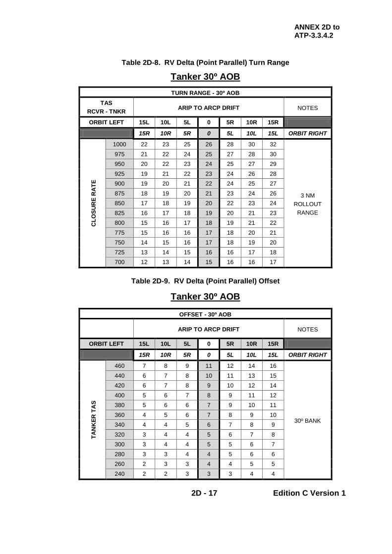
ANNEX 2D to ATP-3.3.4.2
2D - 17 Edition C Version 1
Table 2D-8. RV Delta (Point Parallel) Turn Range
Tanker 30º AOB
TURN RANGE - 30º AOB TAS
RCVR - TNKR ARIP TO ARCP DRIFT NOTES
ORBIT LEFT 15L 10L 5L 0 5R 10R 15R
15R 10R 5R 0 5L 10L 15L ORBIT RIGHT
CLO
SUR
E R
ATE
1000 22 23 25 26 28 30 32
3 NM ROLLOUT
RANGE
975 21 22 24 25 27 28 30 950 20 22 23 24 25 27 29
925 19 21 22 23 24 26 28 900 19 20 21 22 24 25 27
875 18 19 20 21 23 24 26 850 17 18 19 20 22 23 24
825 16 17 18 19 20 21 23 800 15 16 17 18 19 21 22
775 15 16 16 17 18 20 21 750 14 15 16 17 18 19 20
725 13 14 15 16 16 17 18 700 12 13 14 15 16 16 17
Table 2D-9. RV Delta (Point Parallel) Offset
Tanker 30º AOB
OFFSET - 30º AOB
ARIP TO ARCP DRIFT NOTES
ORBIT LEFT 15L 10L 5L 0 5R 10R 15R
15R 10R 5R 0 5L 10L 15L ORBIT RIGHT
TAN
KER
TA
S
460 7 8 9 11 12 14 16
30º BANK
440 6 7 8 10 11 13 15 420 6 7 8 9 10 12 14
400 5 6 7 8 9 11 12 380 5 6 6 7 9 10 11
360 4 5 6 7 8 9 10 340 4 4 5 6 7 8 9
320 3 4 4 5 6 7 8 300 3 4 4 5 5 6 7
280 3 3 4 4 5 6 6 260 2 3 3 4 4 5 5
240 2 2 3 3 3 4 4

ANNEX 2D to ATP-3.3.4.2
2D - 18 Edition C Version 1
Table 2D-10. RV Delta (Point Parallel) Turn Range/Offset Correction – 3 NM Rollout
TURN RANGE ADJUSTMENT CHART
3 NM ROLLOUT RANGE A B C B E F G
PLANNED TURN ACTUAL OFFSET (NM) RANG
E OFFS
ET 0 5 10 15 20 25 13 2 13 14 16 20 24 28
14 3 14 15 17 20 24 29 4 13 14 17 20 24 28
15 4 15 15 18 21 25 29
16 4 16 16 18 22 25 29 5 15 16 18 21 25 29
17
4 17 17 19 22 26 30 5 16 17 19 22 26 30 6 16 17 19 22 25 30 7 16 16 18 22 25 29
18
5 17 18 20 23 26 30 6 17 18 20 23 26 30 7 17 17 19 22 26 30 8 16 17 19 22 26 30
19
5 18 19 21 24 27 31 6 18 19 21 23 27 31 7 18 18 20 23 27 31 8 17 18 20 23 26 30 9 17 17 20 22 26 30
20
6 19 20 22 24 28 32 7 19 19 21 24 27 31 8 18 19 21 24 27 31 9 18 19 21 23 27 31 10 17 18 20 23 26 30
21
7 20 20 22 25 28 32 8 19 20 22 25 28 32 9 19 20 22 24 28 31 10 18 19 21 24 27 31 11 18 19 21 23 27 31
22
8 21 21 23 25 29 32 9 20 21 23 25 28 32 10 20 20 22 25 28 32 11 19 20 22 24 28 32 12 18 19 21 24 27 31
23
9 21 22 23 26 29 33 10 21 21 23 26 29 33 11 20 21 23 25 28 32 12 20 20 22 25 28 32
24
10 22 22 24 27 30 33 11 21 22 24 26 29 33 12 21 21 23 26 29 33 13 20 21 23 25 28 32
25 12 22 23 24 27 30 33 13 21 22 24 26 29 33
26 13 23 23 25 27 30 34 14 22 23 24 27 30 33
27 13 24 24 26 28 31 34 14 23 24 25 28 31 34
28 15 24 24 28 28 31 34
This chart includes all the turn range/offset possibilities in the 400-480 TAS range.
1. Enter chart from left with the planned turn range/offset.
2. Enter from the top with the observed offset as it occurs during the RV.
3. The intersection of these entries is the new turn range at which to command the tanker’s turn.
EXAMPLE: With a planned 20/8 and actual 20 nm offset, the tanker’s turn should occur at 27 nm. NOTE New turn ranges are rounded to the nearest nm.
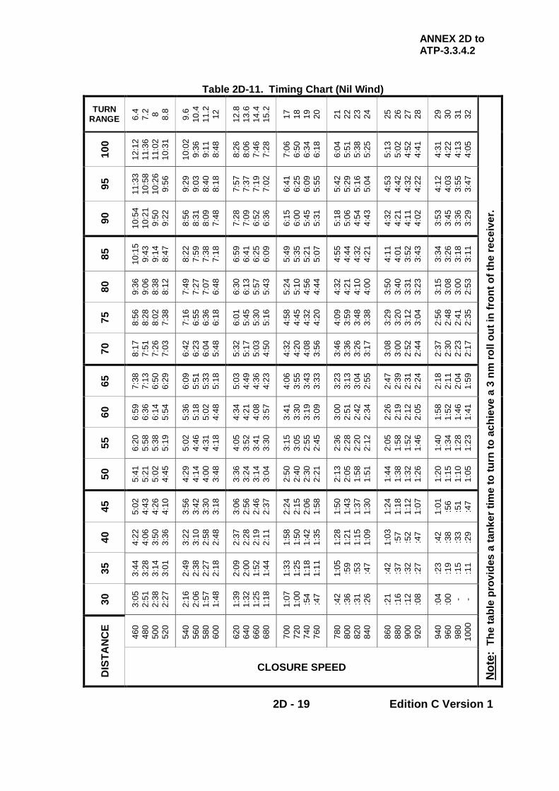
ANNEX 2D to ATP-3.3.4.2
2D - 19 Edition C Version 1
Table 2D-11. Timing Chart (Nil Wind)
TURN RANGE 6.
4 7.
2 8 8.8
9.6
10.4
11
.2
12
12.8
13
.6
14.4
15
.2
17
18
19
20
21
22
23
24
25
26
27
28
29
30
31
32
Not
e: T
he ta
ble
prov
ides
a ta
nker
tim
e to
turn
to a
chie
ve a
3 n
m ro
ll ou
t in
fron
t of t
he re
ceiv
er.
100
12:1
2 11
:36
11:0
2 10
:31
10:0
2 9:
36
9:11
8:
48
8:26
8:
06
7:46
7:
28
7:06
6:
50
6:34
6:
18
6:04
5:
51
5:38
5:
25
5:13
5:
02
4:52
4:
41
4:31
4:
22
4:13
4:
05
95
11:3
3 10
:58
10:2
6 9:
56
9:29
9:
03
8:40
8:
18
7:57
7:
37
7:19
7:
02
6:41
6:
25
6:09
5:
55
5:42
5:
29
5:16
5:
04
4:53
4:
42
4:32
4:
22
4:12
4:
03
3:55
3:
47
90
10:5
4 10
:21
9:50
9:
22
8:56
8:
31
8:09
7:
48
7:28
7:
09
6:52
6:
36
6:15
6:
00
5:45
5:
31
5:18
5:
06
4:54
4:
43
4:32
4:
21
4:11
4:
02
3:53
3:
45
3:36
3:
29
85
10:1
5 9:
43
9:14
8:
47
8:22
7:
59
7:38
7:
18
6:59
6:
41
6:25
6:
09
5:49
5:
35
5:21
5:
07
4:55
4:
44
4:32
4:
21
4:11
4:
01
3:52
3:
43
3:34
3:
26
3:18
3:
11
80
9:36
9:
06
8:38
8:
12
7:49
7:
27
7:07
6:
48
6:30
6:
13
5:57
5:
43
5:24
5:
10
4:56
4:
44
4:32
4:
21
4:10
4:
00
3:50
3:
40
3:31
3:
23
3:15
3:
08
3:00
2:
53
75
8:56
8:
28
8:02
7:
38
7:16
6:
55
6:36
6:
18
6:01
5:
45
5:30
5:
16
4:58
4:
45
4:32
4:
20
4:09
3:
59
3:48
3:
38
3:29
3:
20
3:12
3:
04
2:56
2:
48
2:41
2:
35
70
8:17
7:
51
7:26
7:
03
6:42
6:
23
6:04
5:
48
5:32
5:
17
5:03
4:
50
4:32
4:
20
4:08
3:
56
3:46
3:
36
3:26
3:
17
3:08
3:
00
2:52
2:
44
2:37
2:
30
2:23
2:
17
65
7:38
7:
13
6:50
6:
29
6:09
5:
51
5:33
5:
18
5:03
4:
49
4:36
4:
23
4:06
3:
55
3:43
3:
33
3:23
3:
13
3:04
2:
55
2:47
2:
39
2:31
2:
24
2:18
2:
11
2:04
1:
59
60
6:59
6:
36
6:14
5:
54
5:36
5:
18
5:02
4:
48
4:34
4:
21
4:08
3:
57
3:41
3:
30
3:19
3:
09
3:00
2:
51
2:42
2:
34
2:26
2:
19
2:12
2:
05
1:58
1:
52
1:46
1:
41
55
6:20
5:
58
5:38
5:
19
5:02
4:
46
4:31
4:
18
4:05
3:
52
3:41
3:
30
3:15
3:
05
2:55
2:
45
2:36
2:
28
2:20
2:
12
2:05
1:
58
1:52
1:
46
1:40
1:
34
1:28
1:
23
50
5:41
5:
21
5:02
4:
45
4:29
4:
14
4:00
3:
48
3:36
3:
24
3:14
3:
04
2:50
2:
40
2:30
2:
21
2:13
2:
05
1:58
1:
51
1:44
1:
38
1:32
1:
26
1:20
1:
15
1:10
1:
05
45
5:02
4:
43
4:26
4:
10
3:56
3:
42
3:30
3:
18
3:06
2:
56
2:46
2:
37
2:24
2:
15
2:06
1:
58
1:50
1:
43
1:37
1:
30
1:24
1:
18
1:12
1:
07
1:01
:5
6 :5
1 :4
7
40
4:22
4:
06
3:50
3:
36
3:22
3:
10
2:58
2:
48
2:37
2:
28
2:19
2:
11
1:58
1:
50
1:42
1:
35
1:28
1:
21
1:15
1:
09
1:03
:5
7 :5
2 :4
7
:42
:38
:33
:29
35
3:44
3:
28
3:14
3:
01
2:49
2:
38
2:27
2:
18
2:09
2:
00
1:52
1:
44
1:33
1:
25
1:18
1:
11
1:05
:5
9 :5
3 :4
7
:42
:37
:32
:27
:23
:19
:15
:11
30
3:05
2:
51
2:38
2:
27
2:16
2:
06
1:57
1:
48
1:39
1:
32
1:25
1:
18
1:07
1:
00
:54
:47
:42
:36
:31
:26
:21
:16
:12
:08
:04
:00 - -
DIS
TAN
CE
460
480
500
520
540
560
580
600
620
640
660
680
700
720
740
760
780
800
820
840
860
880
900
920
940
960
980
1000
CLOSURE SPEED

ANNEX 2D to ATP-3.3.4.2
2D - 20 Edition C Version 1
Table 2D-12. Work Sheet - RV Delta (Point Parallel)
Turn Range and Offset– Tanker and Receiver Flying AAR RV Speeds
A B C D E F PARAMETER REFERENCE TANKER RECEIVER
1 ALTITUDE
2 RV IAS TANKER
NATIONAL SRD
3 RV TAS TAB 2D-1 or 2
4 ACTUAL TEMP
5 STD TEMP TABLE 2D-1
6
ACTUAL – STD (Row 4 – Row 5) (<STD = REDUCE BY 1 kt / ºC) (>STD = INCREASE BY 1 kt / ºC)
- +
7 CORRECTED TAS (Row 3±Row 6)
8 CLOSURE TAS (RCVR- TNKR)
9 ARIP TO ARCP DRIFT
DERIVED FROM
TANKER NAV SYSTEM
L/R
10 TURN RANGE TAB 2D-6 or 8
11 OFFSET TAB 2D-7 or 9
12 50 MN TIMING BACKUP TAB 2D-11
13 30 NM TIMING BACKUP TAB 2D-11
Figure 2D-2. Diagram of a Modified RV Delta (Point Parallel)
ANNEX 2E to ATP-3.3.4.2
2E - 1 Edition C Version 1
CHAPTER 2 FIXED WING PROCEDURES ANNEX 2E RV ECHO (TIMING)
2.E.1. INTRODUCTION The RV Echo is a timing based anchor orbit and should be used in tactical situations where it is necessary to have a tanker available with which receivers can RV in a known area on an opportunity basis. The RV Echo is normally used to support Combat Air Patrols (CAPs) and is particularly appropriate when EMCON procedures are in force; see Figure 2E-1. 2.E.2. PROCEDURE
a. Anchor Point. The position of the Anchor Point can be identified in 2 ways:
(1) Range and True Bearing. A range and true bearing from a
reference point with the inbound track to the Anchor Point orientated at right angles and to the left of the radial from the reference point.
(2) Geographic Point and True Track. A geographic point and a true
track which is to be flown towards the Anchor Point.
b. Anchor Duration
(1) Although the normal RV Echo duration is 15 min, to allow for limitations in airspace reservations or operational requirements, it may be defined as an RV Echo 10, 15, 20 etc.
(2) It is vital that the anchor duration is briefed prior to the mission,
as the receiver will use the information to predict the approximate position of the tanker.
c. Tanker Passage Through Anchor Point. The tanker should aim to fly
through the Anchor Point at the RV FL/altitude/height on the hour and then at intervals as dictated by the RV Echo duration.
d. Receiver Join on Tanker
(1) Each receiver homes independently onto the tanker using all
available aids. (2) The receiver is to join the pattern 1000 ft below the RV
FL/altitude/height. (3) Receivers with AI radar or visual contact may join at any suitable
point along the anchor.
ANNEX 2E to ATP-3.3.4.2
2E - 2 Edition C Version 1
(4) Receivers without AI radar should aim to fly the inbound track to
the Anchor Point and adjust their timing to arrive 30 sec after the tanker.
e. Impact of EMCON Procedures. EMCON procedures may be used in
conjunction with the RV Echo. However, in such circumstances, the receivers should be aware that several other receivers/formations may be approaching the tanker from different directions. Therefore, it is essential that all receivers maintain a good lookout and strict adherence to AAR procedures.
f. Tanker Actions to Ensure VMC. Within the limitations of the tactical
situation, the tanker pilot is to adjust the FL/altitude/height and or position of the racetrack to maintain good VMC.
2.E.3. AIDS EMPLOYED TO RV Subject to the EMCON policy in force, all available aids should be employed to achieve the RV. If available, A/A TACAN should be used as follows:
a. The tanker should select the A/A TACAN channel appropriate to the towline or as directed in the SPINS or tasking order throughout its time on station.
b. The tanker may select air to ground mode as necessary to obtain a
position for a navigation fix.
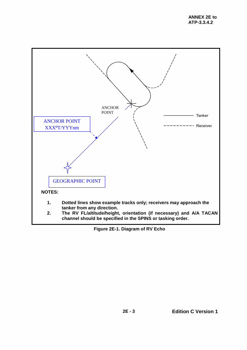
ANNEX 2E to ATP-3.3.4.2
2E - 3 Edition C Version 1
NOTES:
1. Dotted lines show example tracks only; receivers may approach the tanker from any direction.
2. The RV FL/altitude/height, orientation (if necessary) and A/A TACAN channel should be specified in the SPINS or tasking order.
Figure 2E-1. Diagram of RV Echo
GEOGRAPHIC POINT
ANCHOR POINT XXXºT/YYYnm
Anchor Point ANCHOR POINT

ANNEX 2E to ATP-3.3.4.2
2E - 4 Edition C Version 1
INTENTIONALLY BLANK

ANNEX 2F to ATP-3.3.4.2
2F - 1 Edition C Version 1
CHAPTER 2 FIXED WING PROCEDURES ANNEX 2F RV FOXTROT
2.F.1. INTRODUCTION The RV Foxtrot is a sequenced departure normally used in VMC conditions when the tanker(s) and receiver(s) are operating from the same airfield. Tanker and receiver take-offs occur within a few minutes of each other, which eliminates the fuel and time consuming racetracks of the other RV procedures. The collocated procedures have the added advantage that it is usually possible for the tanker to delay its take-off until assured of the receiver’s serviceability on start up. However, adverse climb out weather or ATC considerations may make these procedures impracticable. There are two methods of effecting a RV Foxtrot: the Accompanied Departure / Buddy Climb and the Tailchase. 2.F.2. ACCOMPANIED DEPARTURE / BUDDY CLIMB In this procedure, see Figure 2F-1, the receiver(s) takes off before the tanker and complete(s) a visual circuit of the airfield whilst the tanker takes off; the receiver(s) then joins formation with the tanker in the climb. This method has several advantages:
a. Wake Turbulence. The receiver(s) is not exposed to wake turbulence caused by the heavy tanker.
b. Receiver Unserviceabilities. Receiver(s) unserviceability immediately
after take-off will be known before the tanker is airborne. 2.F.3. ACCOMPANIED DEPARTURE / BUDDY CLIMB - PLANNING
CONSIDERATIONS This method has 2 significant factors that need to be taken into consideration deciding whether or not to employ this RV rather than the Tailchase Departure described below.
a. Fuel Consumption. The receiver(s) consumes extra fuel completing the visual circuit.
b. Ability to Join Up. Weather conditions at the airfield need to be good
enough for a visual circuit and join. Therefore, during the planning phase, careful consideration of factors such as weather conditions and route of flight are required to ascertain the optimal procedure.

ANNEX 2F to ATP-3.3.4.2
2F - 2 Edition C Version 1
2.F.4. ACCOMPANIED DEPARTURE / BUDDY CLIMB – IMPLEMENTATION The method of implementing the Accompanied Departure / Buddy Climb is:
a. Receiver/Tanker Departure. Because airspace reservations are usually based on the tanker flight plan, the tanker take-off time remains the critical planning factor. Therefore, the receiver(s) must take-off ahead of the tanker with sufficient time in hand to fly a visual circuit and still permit the tanker to achieve its Estimated Time of Departure (ETD).
b. Receiver Visual Circuit. The receiver(s) flies a visual circuit and when
the receiver is downwind the tanker then commences a take-off. c. Tanker Departure. The tanker carries out a standard departure; the
receiver(s) continues the visual circuit adjusting speed and track to join the tanker in the climb.
2.F.5. TAILCHASE DEPARTURE In this procedure, see Figure 2F-2, the tanker takes off before the receiver(s). 2.F.6. TAILCHASE DEPARTURE - PLANNING CONSIDERATIONS As the tanker launches first, planning factors must take into consideration that, should one or more receivers fail to get airborne, the tanker will normally continue as planned accompanied by the reduced number of receivers. 2.F.7. TAILCHASE DEPARTURE – ESTABLISHING ARIP The standard method for arranging this departure is to establish a ARIP after tanker top of climb; tanker and receiver take-offs are adjusted to make good the ARIP at the RV control time. The advantage of this method is that it is suitable when weather conditions are relatively poor at the airfield or during the initial stages of the climb. However, if weather conditions are good, the take-offs can be planned so that the receiver(s) join with the tanker in the climb. 2.F.8. TAILCHASE DEPARTURE – IMPLEMENTATION Careful pre-flight briefing between tanker and receiver crews is essential.
a. ARIP. The tanker crew calculates their top of climb position and establishes the ARIP at one minute along track from the top of climb position. A direct climb-out from base is preferable but not essential.
b. ARCT. Knowing the time to height, the ARCT is calculated from the
tanker take-off time.

ANNEX 2F to ATP-3.3.4.2
2F - 3 Edition C Version 1
c. Take-Off Time - Receiver. The receiver calculates its own time for take-off to make good the ARIP and compares that time with the tankers take-off time to ensure adequate separation to avoid the tanker’s wake turbulence.
d. Vertical Separation - Receiver. As soon as practical after take-off, the
receiver is to establish RT contact with the tanker. The receiver is to ensure that its passing FL/altitude/height is at least 1000 ft below that of the tanker until positive visual identification is made.
e. Rate of Climb. An agreed common rate of climb is to be pre-briefed as
laid out in Chapter 2 Annex 2J. f. Height Calls - Tanker. Following the initial RT contact, the tanker is to
call the FL/altitude/height level every 5000 ft until the receiver is in visual contact; this also assists the receiver in maintaining vertical separation. If IMC is encountered by either aircraft prior to the join-up, more frequent height comparisons are to be made to ensure the necessary vertical separation is maintained.
g. Navigation Aids. Usually, tanker and receiver(s) fly identical INS tracks
and A/A TACAN is selected to give split ranges.
(1) If the departure procedures require the use of a ground base TACAN, then range and bearing comparison to this facility is to be made at every height check.
(2) If required, UHF Direction Finder (UDF) may be used to ascertain
relative positions.
h. Orbiting – Tanker. If the receiver has not confirmed visual contact during the climb, the tanker is to make good the ARIP and, with ATC agreement, establish a left hand orbit until join up is complete.
2.F.9. RECEIVERS DEPART BEFORE TANKER Sometimes, the receiver(s) may depart ahead of the tanker(s). In such cases, the procedures listed above remain valid, although the lead formation assumes responsibility for height calls. Once VMC, the formation will co-ordinate with ATC a 1000 ft separation between the receivers and tankers. Additionally, if the tanker is unable to accelerate and overtake the receivers, the formation should arrange with ATC for the receivers to orbit left in order to acquire the tanker.
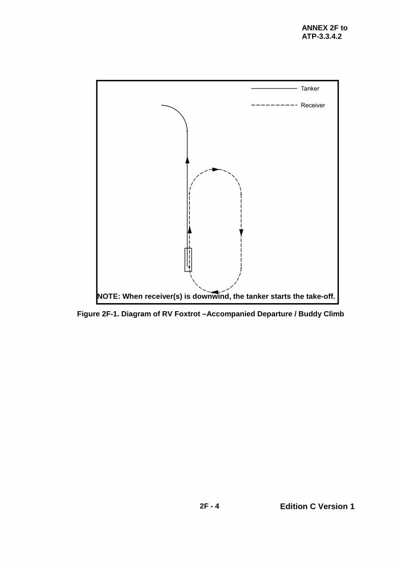
ANNEX 2F to ATP-3.3.4.2
2F - 4 Edition C Version 1
Figure 2F-1. Diagram of RV Foxtrot –Accompanied Departure / Buddy Climb
NOTE: When receiver(s) is downwind, the tanker starts the take-off.
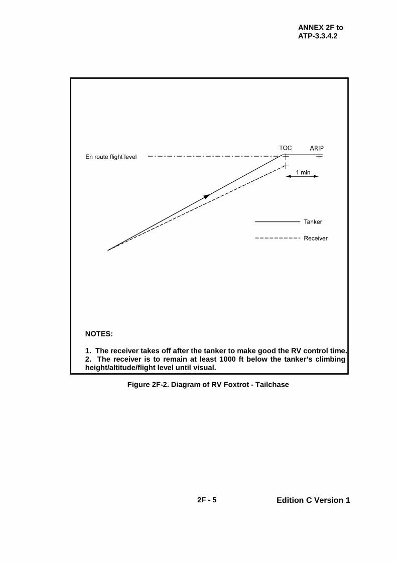
ANNEX 2F to ATP-3.3.4.2
2F - 5 Edition C Version 1
NOTES: 1. The receiver takes off after the tanker to make good the RV control time. 2. The receiver is to remain at least 1000 ft below the tanker’s climbing height/altitude/flight level until visual.
Figure 2F-2. Diagram of RV Foxtrot - Tailchase
ARIP

ANNEX 2F to ATP-3.3.4.2
2F - 6 Edition C Version 1
INTENTIONALLY BLANK
ANNEX 2G to ATP-3.3.4.2
2G - 1 Edition C Version 1
CHAPTER 2 FIXED WING PROCEDURES ANNEX 2G RV GOLF (EN ROUTE)
2.G.1. INTRODUCTION The RV Golf facilitates a join up en-route on a common track to make good a scheduled time to join an ALTRV or other established military corridor; the tanker(s) and receiver(s) may have departed either from the same or different bases. See Figure 2G-1. 2.G.2. BASIC PROCEDURE
a. Arrival at ARIP. The tankers and receiver(s) navigate independently to arrive at the ARIP at a designated ARCT. To counter departure delays or receiver(s) arriving early, it may be necessary for the tanker to arrive approximately 10 min before the receiver(s) and establish an orbit prior to the ARIP.
b. Track Requirements. A common track length equivalent to 15 min
flying time should be planned to allow for tanker descent to RV FL/altitude/height, visual acquisition and timing corrections.
c. Communication Procedures. Fifteen minutes prior to the ARCT the
tanker and receiver(s) are to confirm their FL/altitude/height, A/A TACAN (channel), Mode 3, armament state and timing. The receiver(s) should fly towards the ARCP with A/A TACAN and radar beacon on (if appropriate) at 1000 ft below the base AAR altitude.
d. Visual Acquisition of Tanker(s)/Receiver(s). When established on the
common track, tanker(s) and receiver(s) are to use all available locating aids (EMCON state permitting) to gain visual contact between the tanker(s) and the receiver(s).
2.G.3. VARIATIONS IN EMCON 2 TO BASIC PROCEDURE
a. During EMCON 2, if radio contact between the aircraft has not been established prior to the RV control time, or the adjusted RV control time, tanker(s) and receiver(s) are to maintain their assigned FL/altitude/height and depart the RV to cross the ARCP/ARIP at the ARCT.
b. Aircraft delaying at the ARCP will employ normal orbit procedures unless
otherwise directed. If there is minimal separation between following aircraft or formations using the same track, orbits at the ARCP will require close coordination and thorough crew briefings to ensure vertical separation.

ANNEX 2G to ATP-3.3.4.2
2G - 2 Edition C Version 1
2.G.4. SPECIFIC PROCEDURES IN EMCON 4 If EMCON 4 procedures are in force, the tasking instructions should include control times for both the ARIP and the ARCP. There are 3 basic options for this procedure:
a. Procedure 1. This procedure should be used when the receiver(s) and tanker(s) have a similar transit speed and cruise height.
(1) Tanker. The tanker plans to arrive at the ARIP at the planned RV
FL/altitude/height and RV control time at the AAR speed. (2) Receiver. The receiver(s) arrive(s) at the ARIP 1000 ft below the
tanker at the RV control time plus 30 sec and then adjusts KIAS to a 20 kts overtake on the tanker.
(3) Receiver Visual with Tanker. Once visual with the tanker and
cleared by the tanker, the receiver(s) climbs to the Echelon Left position (drogue) / astern position (boom). A/A TACAN is used throughout to determine relative positions.
b. Procedure 2. This procedure is used when turboprop or jet receiver(s)
have a considerable difference in cruising FL/altitude/height and speed to that of the tanker.
(1) Navigation Aids. A/A TACAN/range to the ARCP is used
throughout the descent to monitor relative positions. (2) Receiver. The receiver arrives at the ARIP at the RV control time
and the RV FL/altitude/height minus 1000 ft. (3) Tanker. The tanker arrives at the ARIP at the RV altitude and the
RV control time plus 1 minute and commences to overtake the receiver, maintaining 1000 ft vertical separation, aiming to pass to overhead a boom receiver or at least 2 wingspans to the right of a probe and drogue receiver.
(4) Join
(a) Boom. On passing the receiver, the tanker is to reduce to
AAR speed. Once visual with the tanker and cleared to join, the receiver is to commence a climb to the astern position.
(b) Probe and Drogue. Once the tanker and receiver are
visual, the tanker descends to the RV FL/altitude/height minus 1000 ft. On the final approach to overtake, tanker speed is to be reduced to receiver speed + 5 kts and the tanker is to pass on the receiver’s right-hand side with a displacement of at least 2 wingspans.

ANNEX 2G to ATP-3.3.4.2
2G - 3 Edition C Version 1
c. Procedure 3. This is a modification of the Procedure 2 and is normally used by Probe and Drogue tankers for jet receivers that have a considerable difference in cruising FL/altitude/height and speed to that of the tanker.
(1) Receiver. The receiver plans to arrive at the ARIP and RV
FL/altitude/height minus 1000 ft at the RV control time. (2) Tanker. The tanker arrives at the ARIP at a higher
FL/altitude/height at the RV control time plus 30 seconds and then commences a descent to level off at the RV FL/altitude/height.
(3) Tanker Descent. During the descent, the tanker establishes a 20
kts overtake on the receiver and uses the A/A TACAN/range to the ARCP to monitor relative positions.
(4) Tanker Visual with Receiver. When visual with the receiver, the
tanker speed is reduced to the receiver’s speed + 5 kts and the receiver climbs to the RV FL/altitude/height and establishes in the position Echelon Left of the tanker.
NOTE
THIS PROCEDURE MAY BE USED WITH THE POSITIONS OF THE TANKER AND RECEIVER REVERSED. IN THIS CASE THE PROCEDURE REMAINS IDENTICAL, EXCEPT THAT THE TANKER, ONCE JOINED WITH THE RECEIVER, OVERTAKES THE RECEIVER AS DESCRIBED IN PARA 0204G.b. ABOVE.
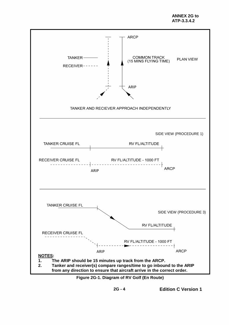
ANNEX 2G to ATP-3.3.4.2
2G - 4 Edition C Version 1
SIDE VIEW (PROCEDURE 1)
SIDE VIEW (PROCEDURE 3)
NOTES: 1. The ARIP should be 15 minutes up track from the ARCP. 2. Tanker and receiver(s) compare ranges/time to go inbound to the ARIP
from any direction to ensure that aircraft arrive in the correct order. Figure 2G-1. Diagram of RV Golf (En Route)
ARIP
ARIP
ARIP

ATP-3.3.4.2
2 - 20 Edition C Version 1
CHAPTER 2 FIXED WING PROCEDURES SECTION II - FORMATION PROCEDURES
2.13. INTRODUCTION The procedures for safe rendezvous, joining, refuelling and leaving the tanker are detailed in Chapter 2 Sections I and IV. This section describes factors that must be taken into account when a formation of receivers and/or tankers operates together. 2.14. FLIGHT SAFETY For flight safety reasons, it is important that these procedures are uncomplicated and unambiguous; furthermore, it is essential that there should be a high degree of commonality between tactical and strategic formation procedures. To minimise complications, these procedures are uniformly applicable by day and by night; these are essential prerequisites to making AAR practicable under EMCON. 2.15. FORMATION CONTROL The commander of the tanker (or lead tanker in multiple tanker formations) is responsible for the control and safe navigation of AAR formations. 2.16. WINGMAN/RECEIVER RESPONSIBILITIES To ensure safe operations and integrity of the formation, wingman are to:
a. Keep the leader in visual or electronic contact at all times. b. Maintain briefed position at all times. c. Anticipate corrections/changes and plan accordingly. d. Monitor all aspects of formation operations and advise the receiver
formation leader if an unsafe condition is identified. 2.17. AIRSPEEDS AND ALTITUDES The optimum altitude and airspeed for AAR varies with the tanker/receiver combination. See tanker National SRD for appropriate details. 2.18. WEATHER/VISIBILITY Refer to Chapter 2 Section I, para. 2.2.d.

ATP-3.3.4.2
2 - 21 Edition C Version 1
2.19. SINGLE TANKER FORMATIONS Usually, tactical AAR involves receivers joining individually or in groups to refuel from one tanker and then depart. However, for training purposes, time with the tanker may be prolonged.
a. Visual Meteorological Conditions (VMC). For VMC, the tanker should brief a formation most suited to the AAR sequence, taking into consideration the formation preferences of the receiver leader. In most cases, aircraft that are not refuelling will be directed to remain in either the Echelon Left or Echelon Right position/area. Should the tanker clear receivers to maintain a loose formation, they are not to stray too far away from the tanker, otherwise they may conflict with other airspace users. Local ATC restrictions may stipulate more stringent requirements, but, generally, the formation frontage should not exceed 1 nm and receivers must stay within ±200 ft of the tanker’s height.
b. Instrument Meteorological Conditions (IMC). Whenever ATC and fuel
considerations permit, tankers should avoid IMC by implementing track or height adjustments.
(1) Climb to VMC. Receiver performance capabilities (particularly
for AAR at high weights) may be a limiting factor; nevertheless, tankers should consider climbing to achieve VMC for cruise and initial AAR contact and then toboggan as receiver weight increases.
(2) Unable to Avoid IMC. If IMC cannot be avoided, the receivers
are to be ordered into the close formation which will give them the best opportunity to retain visual contact with the tanker.
(a) Receivers should be arranged so that movement around
the tanker is minimised during AAR sequences. (b) Extended echelon formations can be difficult and tiring to
fly, particularly under prolonged IMC. Thus, receivers should be apportioned equally (as far as possible) to the left and right echelon positions on the tanker.
(c) The tanker is to exercise strict control of receiver
movement around the tanker during formation changes for AAR brackets.
(d) Receiver Loss of Visual Contact. If the receivers lose
visual contact with the tanker, they are to immediately implement the ‘Lost Wingman” procedures laid out in Chapter 2 Section IV and maintain the prescribed separation until visual contact is regained.
ATP-3.3.4.2
2 - 22 Edition C Version 1
2.20. DETAILED FORMATION PROCEDURES
a. Multi-Tanker Formation Procedures. Chapter 2 Annex 2H provides information about multi-tanker formation procedures.
b. Force Extension Procedures. Chapter 2 Annex 2I provides information
about force extension procedures. c. Tanker Snake/Formation Climb. Chapter 2 Annex 2J provides a guide
to tanker snake/formation climb procedures. d. Alternative AAR Formation Procedures – Heavy Aircraft. Chapter 2
Annex 2K discusses alternative AAR formation procedures for heavy aircraft.
e. Receiver Station Keeping Equipment (SKE) - AAR Procedures.
Chapter 2 Annex 2L provides guidance on the use of SKE when flying heavy aircraft in formation with tankers.
f. Quick Flow Procedures. Chapter 2 Annex 2M describes receiver
actions when employing Quick Flow procedures.

ATP-3.3.4.2
2 - 23 Edition C Version 1
INTENTIONALLY BLANK
ANNEX 2H to ATP-3.3.4.2
2H - 1 Edition C Version 1
CHAPTER 2 FIXED WING PROCEDURES ANNEX 2H MULTI-TANKER FORMATION PROCEDURES
NOTE
THE US AND RNLAF DO NOT FLY MULTI-TANKER ECHELON PROCEDURES AS DESCRIBED IN THIS ANNEX. US PROCEDURES ARE PUBLISHED IN APPROPRIATE NATIONAL DOCUMENTS AND SUMMARISED IN CHAPTER 2 ANNEX 2K.
2.H.1. MULTI-TANKER FORMATION - ECHELON PROCEDURES On occasions, tasking may require several tankers to be in formation during the RV and for refuelling. Tankers may fly in Echelon Right formation on the lead tanker.
a. Formation Turns. At the lead tanker’s discretion, the other tankers may go to line astern formation for turns prior to and during a RV procedure; however, they must resume Echelon Right prior to the receivers joining formation.
b. Receivers Joining a Tanker Formation
(1) Fighter and Heavy Probe and Drogue Receivers. All fighter
and heavy probe and drogue receivers joining a multi-tanker formation are to join on the left of the tanker formation.
(2) Heavy Boom Receivers. All heavy boom receivers will join
either directly behind the boom or, if there is more than one heavy receiver, the second and subsequent receivers will join on the right of the tanker formation.
(3) Receivers and Assigned Tankers. At the appropriate time,
receivers will be cleared to join their assigned tanker.
(a) Receivers are not to penetrate through the tanker formation to reach their tanker.
(b) Receivers are to drop back on the left of the tanker
formation, then move across behind the formation, before moving forward to join their tanker.
ANNEX 2H to ATP-3.3.4.2
2H - 2 Edition C Version 1
2.H.2. FORMATION IN VISUAL METEOROLOGICAL CONDITIONS (VMC)
a. After joining, the standard cruise formation is with the tankers in echelon formation on the right side of the lead tanker.
b. If the lead and the formation tanker(s) have concurrent AAR
commitments, then the formation tanker(s) should establish a loose echelon position where the autopilot can be engaged to provide a steady AAR platform for the receivers.
c. Ideally, when more than 3 tankers are allocated to a wave, the fourth
and subsequent tankers should be formed into a separate section 3 nm in trail from the leading section, using an A/A TACAN or TCAS range from the lead tanker; this eases the tankers’ station keeping task and keeps the formation frontage within reasonable bounds.
(1) Where possible, the formation should remain clear of cloud. (2) Provided sufficient visual cues remain, the formation may
penetrate thin cloud.
(a) The No 2 tanker should be brought to close right echelon on the lead tanker and the receivers put into close left echelon on the lead tanker.
(b) If there is a third tanker, this should be placed in line
astern behind the second tanker to ease the station keeping task.
(c) If there is a second section, then this should remain 3 nm
behind of the lead tanker.
(3) The lead tanker will be able to refuel its receivers if these conditions prevail during the brackets.
(4) At the conclusion of the lead tanker’s AAR duties, the receivers
will be able to take formation on the station keeping tankers, freeing the lead tanker to hand over the lead and leave the formation by a level turn to the left.
(5) If the AAR plan requires concurrent AAR from the other tanker(s),
then it is not practicable for the tanker(s) to hold close formation and provide a steady AAR platform. In this event, tankers are to take up a Standard Separated Formation, with the receivers in a discrete formation around their allocated tanker.

ANNEX 2H to ATP-3.3.4.2
2H - 3 Edition C Version 1
Figure 2H-1. Diagram of VMC Multi-Tanker Formation
2.H.3. FORMATION IN INSTRUMENT METEOROLOGICAL CONDITIONS (IMC) - STANDARD SEPARATED FORMATION
a. Tankers within each section are to be in right echelon, approximately
1000 m and 30° displaced from and 1 nm behind of the preceding tanker; radar, TCAS and A/A TACAN ranges are to be used to maintain the prescribed displacement.
b. If there is a second section of tankers, then tanker 4 is to maintain a
range of 3 nm behind the lead tanker, and so on. c. The lead tanker is to make frequent broadcasts of its heading and speed
whilst IMC prevail. d. If an aircraft cannot maintain the prescribed separation because of
radar/TCAS/TACAN unserviceabilities, a safe height separation from the rest of the formation is to be achieved; the tanker leader is to be informed.
Height ± 200 ft

ANNEX 2H to ATP-3.3.4.2
2H - 4 Edition C Version 1
Figure 2H-2. Diagram of IMC Multi-Tanker Formation 2.H.4. TANKER LEAD CHANGE There are several ways in which 2 tankers may change the lead when flying in visual contact. Provided good airmanship is applied, the lead change may be carried out in a manner suited to the particular circumstances. A maximum overtake speed of 10 kts is recommended. If a higher speed is used in poor visibility, it is possible that the new No 2 will lose sight of the leader before joining formation. For the same reason, lateral separation should not be more than about 200 m. A recommended procedure suitable for most circumstances is as follows:
a. The leader passes its datum heading and speed to the No 2 and orders him to overtake on the appropriate side.
b. No 2 accelerates to overtake the leader on a 5o divergent heading,
climbing 200 ft above the leader’s level. No 2 should aim to put himself slightly high in the leader’s 3/9 o’clock moving forward to the 2/10 o’clock position.
Height ± 200 ft

ANNEX 2H to ATP-3.3.4.2
2H - 5 Edition C Version 1
c. As soon as the leader has visual contact with the No 2, the leader
formally hands over control and maintains echelon on the new leader until otherwise ordered.
d. If at any stage during the overtake the No 2 loses sight of the leader
before the leader calls ‘visual’, the No 2 must immediately take collision avoidance and report its actions to the leader.
2.H.5. MULTI-TANKER FORMATION PROCEDURES. The formations described in this Annex are an alternative to close echelon formation and may be adopted at any stage in the cruise at the discretion of the lead tanker.
a. Pre-Flight Brief. Before a tanker formation is flown, a full and formal brief is to be given by the formation leader. The main briefing points to be covered for a snake/formation climb are outlined in Annex 2J.
b. Formation Considerations. The following is merely a guide to
formation procedures and cannot cover all situations. Crews are to use their judgement when circumstances dictate, e.g. in conditions of reduced visibility.
(1) Formation Leaders. Formation leaders are responsible for their
entire formation. Differing performance capabilities of other aircraft require additional considerations, particularly when dissimilar aircraft are mixed in a single formation.
(2) Formation Members. Formation members are to make every
effort to maintain correct positioning and are to be prepared to provide assistance to the formation leader or to assume the formation lead if required.
(3) Standard Formation. The standard formation is flown with
successive tankers in line astern and stepped up behind the leader.
(4) Formation Weather Limits – Non-AI Radar Aircraft. For non-AI
equipped receivers or non-SKE equipped tankers, weather limits for formation are 1000 ft clear of cloud, one nm visibility plus one nm of visibility per tanker in the formation.
(5) Formation Weather Limits – AI Radar Aircraft. For AI
equipped aircraft the weather limits are as prescribed for each nation.
(6) Formation Size. Normally, the formation is to comprise a
maximum of 3 tankers.

ANNEX 2H to ATP-3.3.4.2
2H - 6 Edition C Version 1
(a) In VMC, the normal separation between tankers is to be 500 ft and 1 nm but this may be reduced at the discretion of the formation leader in VMC to a minimum of 500 ft and ½ nm.
(b) In IMC the minimum separation is to be 1000 ft and 1 nm.
(7) Altitude Block. An altitude block is to be used whenever
possible. If an altitude block is not available, each tanker is to have a separate IFR altitude assigned.
Figure 2H-3. Diagram Of Multi-Tanker Formation
c. Take-off. If receivers are part of the formation from take-off, they should normally take-off first. Take-off intervals or sequence may be varied as necessary depending on aircraft acceleration and performance, training requirements, weather, airfield conditions and mission requirements. All aircraft are to use the runway centreline for alignment. The effects of turbulence and vortex generation increase as the take-off roll progresses, reaching a maximum at unstick. The effects of turbulence may be decreased after take-off by turning slightly left or right as soon as possible after getting airborne to place the aircraft upwind (if possible) and out of the vortex of the preceding aircraft.
(1) Tanker Snake/Formation Climb Procedures. Usually, tankers
will take-off from the same base in order to establish formation. Chapter 2 Annex 2J outlines the snake/formation climb procedures for all types of tankers. Dissimilar tanker types are to

ANNEX 2H to ATP-3.3.4.2
2H - 7 Edition C Version 1
fly a pre-briefed speed and rate of climb until joined up. A full brief is to be given by the formation leader.
d. Establishing Formation. Normally, the briefed formation disposition is
to be established after cruising altitude is reached; formation disposition may be established directly or from echelon. Each tanker is to call when ‘in position’. To establish formation disposition from echelon:
(1) VMC
(a) For 2 tankers, No 2 drops back and climbs into position
maintaining visual contact with the lead. (b) For 3 tankers, No 3 maintains formation on No 2 until No
2 is in position then drops back further and climbs into its own position.
(2) IMC
(a) For 2 tankers, No 2 first attains a ½ nm lateral spacing
using the loss of visual contact procedure, then climbs to the appropriate altitude before dropping back into position directly behind the lead.
(b) For 3 tankers, No 3 is to move into its formation position
first. When No 3 is in position, No 2 is then to establish its own formation position in turn.
e. Rendezvous. Turns in formation should be minimised to ease the
station keeping task and tankers are not to exceed 25° AOB (if tanker national restrictions direct the use of AOB less than 25º, ATC should be informed). Aircraft joining the formation should join in the normal manner 1 nm and 1000 ft below the lead tanker.
(1) Tankers joining a formation are to be passed the formation
position to be adopted and an individual formation callsign numbered sequentially with No 1 as the lead.
(2) Receivers joining a formation are to state ‘visual with xx number
of tankers’ before the lead tanker instructs the receiver(s) to join a specific tanker (using the tanker’s formation position, not callsign).
(3) Safety. Aircraft joining a formation are not to enter the formation
until all aircraft in the formation have been visually identified.
f. Maintaining Formation. Maintaining correct formation positioning requires constant attention and effort. The lead tanker is to fly as stable a platform as possible and is to call all changes of heading, height or airspeed. Any deviation from the stated parameters will be magnified

ANNEX 2H to ATP-3.3.4.2
2H - 8 Edition C Version 1
with each succeeding aircraft. Subsequent tankers should maintain position by reference to the lead tanker using A/A TACAN, radar, TCAS and visual references. If there is significant drift, aircraft will not fly ‘nose to tail’ but will fly crabbed relative to each other.
(1) Speeds. At medium cruising levels, due to differences in TAS, it
will be necessary for following aircraft to fly about 5 KIAS slower for every 1000 ft they are above the lead. The lead tanker will fly the planned formation speed which will be dependent on tanker/receiver limitations and separately briefed. In some cases this may have to be increased so that the last tanker is not below the minimum speed for the receiver type.
(2) Turns. To maintain position, all aircraft must start the turn over
the same geographical point. Succeeding tankers will therefore start the turn after an appropriate delay, which will depend on TAS and separation. The lead tanker should use 10o AOB for turns up to and including 20o
and 25o AOB for turns of more than
20o (if tanker national restrictions direct the use of AOB less than
25º, ATC should be informed). Any necessary track adjustment due to wind in the AAR area is to be made on the straight legs; the bank angle is not to be increased during the turn.
NOTE
SOME TANKERS WITH RECEIVER(S) IN CONTACT, ARE RESTRICTED TO 20° AOB. SEE NATIONAL SRDs FOR DETAILS
(3) Climbs/Descents
(a) VMC. In VMC, the lead tanker may elect to climb or
descend the formation as a formation. (b) IMC. In IMC, climbs or descents as a formation are not
permitted and are to be accomplished by tanker elements moving individually. All movements are to be controlled by the lead tanker.
(i) For a descent, the lead descends first. (ii) When established, the lead calls its new level and
instructs No 2 to descend to its new level.
(iii) When No 2 has called at its new level, the lead instructs No 3 to descend and so on.
(iv) For a climb, the reverse procedure is to be used
with the rear tanker moving first and the lead tanker last.
ANNEX 2H to ATP-3.3.4.2
2H - 9 Edition C Version 1
(4) Autopilot Operation. The autopilot is to be used to reduce fatigue and aid in altitude separation. Consideration is to be given to placing an aircraft with an inoperative or malfunctioning autopilot in the last position in the formation for extended periods of formation.
(5) A/A TACAN. A/A TACAN should be used in the normal manner.
If each tanker has 2 TACANs, a channel pairing should be specified between No 1 tanker and No 2 tanker, and a separate pairing should be specified between No 2 tanker and No 3 tankers (the aircraft in front selects the higher channel). The lead should use its second TACAN for range (and bearing) for the receivers as normal.
(6) Formation Position Changes. Formation position changes must
be carried out in a prompt but formal manner. To change the lead, the lead tanker calls the datum heading, height and speed and instructs No 2 to overtake (normally on the right).
(a) VMC. No 2 descends towards the echelon position on the
lead and carries out a standard lead change.
(b) IMC
(i) No 2 establishes ½ nm lateral separation from the lead tanker using loss of visual contact procedure, then increases speed by 10-15 KIAS and overtakes maintaining level.
(ii) When No 1 is able to maintain separation on No 2
(using A/A TACAN, TCAS and radar), No 1 hands over the lead.
(iii) No 2 takes the lead, reduces to formation speed,
renumbers the formation if applicable, instructs the new No 2 to climb into position and descends into the lead position.
(iv) A similar procedure is to be used for other position
changes within the formation.
(c) Radar and/or Visual Contact. Radar or visual contact must be maintained throughout the position change.
(i) If radar and visual contact is lost during a position
change, maintain altitude and advise the formation leader that contact has been lost.
(ii) The formation member losing contact is to ensure
positive separation by any means available and

ANNEX 2H to ATP-3.3.4.2
2H - 10 Edition C Version 1
must not attempt to rejoin the formation until positive radar or visual contact is established.
(d) Renumbering of Formation Members. Aircraft changing
position are to assume the callsign of their new position. When all aircraft are level at their new altitude and established in their new position, they are to acknowledge with their new formation callsign.
(7) Refuelling. During refuelling, the formation lead must fly precise
airspeeds, altitudes and heading in order to maintain a stable platform for aircraft in the formation. Any deviation from these parameters requires corrections which increase in magnitude with each succeeding aircraft. Therefore, formation aircraft are to maintain their position relative to the lead aircraft. This prevents the ‘accordion’ effect during refuelling and possible conflict with other aircraft in the formation. Receivers with large onloads at high gross weight may require airspeeds to rise as onload increases. Maintaining formation in this scenario may be extremely difficult and the formation leader should plan for this eventuality and brief/co-ordinate actions accordingly.
(8) En Route / Straight Track. If necessary, the receivers can be
towed to a drop off point, as specified in the ATO. When the formation is flying a long straight track (IMC or VMC), tankers can establish a 60° echelon on the tanker ahead:
(a) When the tanker to large receiver ratio is one to one or
greater (i.e. 3 tankers and 2 receivers), 2 nm spacing stacked up 500 ft will normally be used.
(b) When the tanker to large receiver ratio is less than one to
one (i.e. 2 tankers and 4 receivers), 2 nm spacing stacked up 1000 ft will normally be used.
(c) For all fighter type receivers, 1 nm spacing stacked up
500 ft will normally be used.
(9) Use of Radio. Formation management usually requires the use of full RT. This situation demands strict radio and intercom discipline from all aircraft in the formation.
(a) Cockpit intercom and RT are to be brief and, if possible,
not made when the receiver is closing to or in the contact position.
(b) Boom operator RT is to be brief but adequate and include
the entire Callsign identification.
ANNEX 2H to ATP-3.3.4.2
2H - 11 Edition C Version 1
(c) If RT silence is operationally essential, all aspects of formation disposition, particularly the RV and join, are to be specifically pre-briefed.
(d) In the normal case when full RT is available, refuelling
should normally be conducted using Radio Silence to reduce RT and avoid possible confusion between receivers. However, if full RT is used for refuelling, callsigns should not be abbreviated.
(10) EMCON. EMCON is to be the minimum required for flight safety
and will depend on prevailing weather conditions.
(11) Receivers
(a) Receivers are to join the formation at 1 nm and 1000 ft below the lead (lowest) tanker on the left and, when cleared by the tanker formation leader, move up to their assigned tanker.
(b) Preferably, there are not to be more than 4 receivers per
tanker.
(c) Flow through the tanker is to be left to right.
(i) If receivers require topping up they are to resume left echelon after initial refuelling.
(d) Once refuelling is complete, all receivers are to establish
right echelon and, if possible, climb 1000 ft above the formation before departing.
(e) Any receiver that loses visual contact with its tanker is to
carry out the loss of visual contact procedure specified in Chapter 2, para. 2.30. or 2.31. as appropriate.
(i) The lead tanker is to co-ordinate the rejoin, as
applicable.
(12) Breakaway. It is essential that a Breakaway transmission is prefaced by the appropriate tanker Callsign. Refer to Chapter 2, para. 2.32. for subsequent actions.
(13) Weather Radar. The lead tanker is to maintain weather watch for
the whole formation. (14) Loss of Contact - Multi-Tanker Formation. See Chapter 2
para. 2.31. for Loss of Visual Contact procedures.

ANNEX 2H to ATP-3.3.4.2
2H - 12 Edition C Version 1
INTENTIONALLY BLANK
ANNEX 2I to ATP-3.3.4.2
2I - 1 Edition C Version 1
CHAPTER 2 FIXED WING PROCEDURES ANNEX 2I FORCE EXTENSION PROCEDURES
2.I.1. AAR DEPLOYMENTS (FORCE EXTENSION) AAR deployments, also known as Force Extension missions, utilise tankers to deploy receivers along a pre-prepared route which may be promulgated in an ATO or a route brief and which may include an ALTRV. Often, a considerable portion of the route is flown with the receiver and tanker in company. On occasions, at least a part of the route may include the presence of several tankers. The general procedures established for single or multi-tanker formations should apply, where possible. Options for deployment formation procedures are presented below and specific instructions are laid out in national instructions; as a general principle, the type of formation to be adopted should be decided and briefed before take-off. 2.I.2. USE OF AAR FOR FORCE EXTENSION Where force extension procedures are employed, force extension tankers (also known as ‘whirlers’) provide AAR for tankers escorting fighters during deployment operations. Force Extension missions are often complex and demanding to all aircrew, especially in IMC. All facets of the mission, to include the RV, formation, air refuelling, VMC/IMC rejoin procedures, and formation break-up are to be briefed during mission planning and clearly understood by all participants. 2.I.3. FORCE EXTENSION PROCEDURES When deploying packages of aircraft, particularly fighters, force extension (or trail) procedures may be employed. The procedures detailed below are the standard for force extension tankers providing AAR to escort tankers. Any deviations to these procedures are to be co-ordinated between all tankers (escorting and force extension), receivers, and the mission commander. If a pre-departure briefing is not conducted due to geographically separated departure locations, the escorting tanker will coordinate changes in flight to the force extension tanker upon initial contact, prior to the AAR RV.
a. Basic Join Principles. The RV Delta (Basic Point Parallel) or RV Golf (En route Rendezvous) usually offer the most convenient process to gather the tanker and receiver aircraft.
b. Transit Formation. Once together, multi-ship tanker formation should
plan to fly 60º echelon, 2 nm spacing unless otherwise directed. c. Formation in IMC. Missions that encounter IMC conditions during air
refuelling may increase air refuelling echelon formation spacing from 2 nm to 3 nm.

ANNEX 2I to ATP-3.3.4.2
2I - 2 Edition C Version 1
d. Join with Force Extension Tanker(s). If a mid-transit tanker (or ‘whirler’) RV is planned, the escorting tanker will attempt to contact the force extension (or ‘whirler’) tanker and exchange information that will assist the AAR join. In-flight visibility will be the determining factor in utilising VMC versus IMC procedures to conduct air refuelling.
NOTE
FOR THE PURPOSE OF THESE PROCEDURES, THE USAF DEFINES VMC AS VISIBILITY EQUAL TO OR GREATER THAN 2 NM. SIMILARLY, THEY DEFINE IMC AS VISIBILITY LESS THAN 2 NM.)
e. Join Force Extension Tanker - VMC. When cleared by the escorting
tanker pilot, receivers will join on the force extension tanker in the Echelon Left position or as directed by the force extension tanker. Once all receivers have joined the force extension tanker, the escorting tanker will be cleared for refuelling. Receivers should fly a loose wing formation and, with the exception of receivers behind the boom or drogues executing the manoeuvre, remain with their force extension tanker in the event that a breakaway is called.
f. AAR Speeds. The tanker will inform receivers the speed to be used as
the refuelling airspeed for the formation (normally, for large aircraft tankers, this will be in the range 290-310 KIAS). The lead force extending tanker will determine air refuelling airspeed based on receiver/tanker aircraft types, altitude, weight, weapons load, etc.
g. Join Force Extension Tanker - IMC or Night. Air-to-air radar equipped
fighters, when cleared by the escorting tanker pilot, should adopt one of the following formation positions:
(1) Close Formation with Force Extension Tanker. With the
agreement of the Force Extension tanker, position in close formation on both wings of the Force Extension Tanker.
(2) Trail. If close formation is not practical, the receiver formation
should position 1.5 to 2 nm in trail (6 o'clock position) of the escorting tanker, 2000 ft (or as briefed) below their assigned tanker whilst it is being refuelled by the force extension tanker.
(a) AI radar or other electronic means should be used to
confirm longitudinal separation.
h. Post Refuelling Procedures
(1) Once all AAR is complete, the escorting tanker(s) will descend 1000 ft below the force extension tanker, offset slightly to the right, and then move to a position 1 nm in front of the force extension tanker(s).

ANNEX 2I to ATP-3.3.4.2
2I - 3 Edition C Version 1
(2) Once the escorting tanker(s) is stabilized in this position, it will assume lead for the formation after a positive verbal lead change.
(3) The escorting tanker will then clear the fighters forward to rejoin. (4) Non-air-to-air radar equipped fighters and other aircraft will rejoin
visually with their respective escorting tanker. (5) If required, air-to-air radar equipped fighters will rejoin using
radar guidance.
i. Rejoin in IMC. If IMC prevails and poor visibility precludes visual rejoins, some nations may permit the force extension tanker(s) to momentarily reduce separation to 1/2 nm and 500 ft vertical separation to facilitate the rejoin. See Chapter 2 Section I, para. 2.2.d.
j. Inability to Rejoin by End of Track. If the formation reaches the end of
the AAR track and visual rejoins are not possible, fuel permitting, force extension tankers will continue along the receiver’s route of flight until visual rejoins are possible. If the force extension tanker(s) reaches BINGO FUEL at, or after the end of the AAR track and the fighters/receivers have not rejoined with the escorting tanker(s), the entire formation will abort to a suitable alternate airfield.
k. Formation Deconfliction Prior to Separation. The tanker radar should
be used for position monitoring throughout the manoeuvre. It is the force extension tanker’s responsibility to inform the entire formation of current heading and airspeed until relieved of that responsibility by a lead change.
(1) The force extension tanker/formation will reform at the top of the
air refuelling block. (2) Once the fighters have rejoined on their respective escorting
tankers, the escorting tanker/ formation will reform at the bottom of the block.
(3) Formation separation will be accomplished by the force extension
or escorting tanker formation increasing/decreasing airspeed as determined by mission requirements and/or the permission brief.
(4) Force extension or escorting tankers will not make any climbing
or descending turns to depart the stream until the tankers are identified visually or by radar, are well clear, and verbal co-ordination is made between tanker formation leaders. All aircrews must clear aggressively and be cognizant of potential converging headings or conflicts.
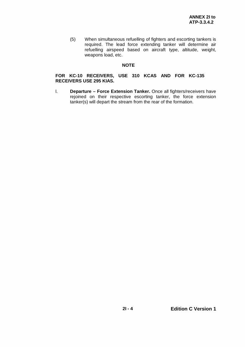
ANNEX 2I to ATP-3.3.4.2
2I - 4 Edition C Version 1
(5) When simultaneous refuelling of fighters and escorting tankers is required. The lead force extending tanker will determine air refuelling airspeed based on aircraft type, altitude, weight, weapons load, etc.
NOTE
FOR KC-10 RECEIVERS, USE 310 KCAS AND FOR KC-135 RECEIVERS USE 295 KIAS.
l. Departure – Force Extension Tanker. Once all fighters/receivers have
rejoined on their respective escorting tanker, the force extension tanker(s) will depart the stream from the rear of the formation.

ANNEX 2J to ATP-3.3.4.2
2J - 1 Edition C Version 1
CHAPTER 2 FIXED WING PROCEDURES ANNEX 2J TANKER SNAKE/FORMATION CLIMB GUIDE
Item (a)
Lead Aircraft (b)
Subsequent Aircraft (c)
Pre-flight Briefing
Brief should include, but is not restricted to, the following points: 1. Weather for T/O, en route, AAR, destinations and alternates. 2. ATC callsigns, individual formation callsigns, T/O time and R/T check in
times (1). 3. Aircraft, parking locations, POB, fuel for each aircraft. 4. 1.35g buffet (VC10), buffet boundary (TriStar), 1.5 Vmm (KC-10) for each
aircraft. 5. Differences in aircraft performance/dissimilar types (2). 6. COMMS/EMCON plan and allowable emitters, A/A TACAN channels and
R/T channels/frequencies and inter-aircraft frequencies. 7. Taxi plan/sequence. 8. T/O and departure routeing, covering abort and emergencies plan and wake
turbulence. 9. Flap retraction height/point (VC10), flap retract schedule (TriStar),
Acceleration Height (KC-10/KC-135). Standard flap retract height for all aircraft in a formation climb with dissimilar tankers is 1500 ft (unless noise abatement procedures dictate otherwise).
10. Power settings. 11. Climb/cruise speeds and rate of climb/vertical speeds (below and above
10,000 ft). Intermediate level offs, turns and bank angles. 12. Transition altitude. 13. VMC/IMC procedures. 14. Formation join up, altitude block, airspeed (indicated/true/mach) and
minimum manoeuvre airspeed. RV join procedure, ARCT and position in formation.
15. Any formation position changes. 16. AAR plan, receiver callsigns and assigned tanker, off/on loads, sequence,
base altitude, track, type of RV. 17. Safety - Loss of Visual Contact procedures. 18. Formation break up and base recovery. 19. Tanker lighting (KC-10/KC-135).
T/O-40 Call for ‘RT CHECK’. A/A TACAN ON, CHECKED, as reqd.
RT check with leader. A/A TACAN ON, CHECKED, as reqd.
T/O-20 Call for ‘START CLEARANCE’ for all aircraft. Start engines.
Start engines. Call ‘READY’ when ready to taxi.
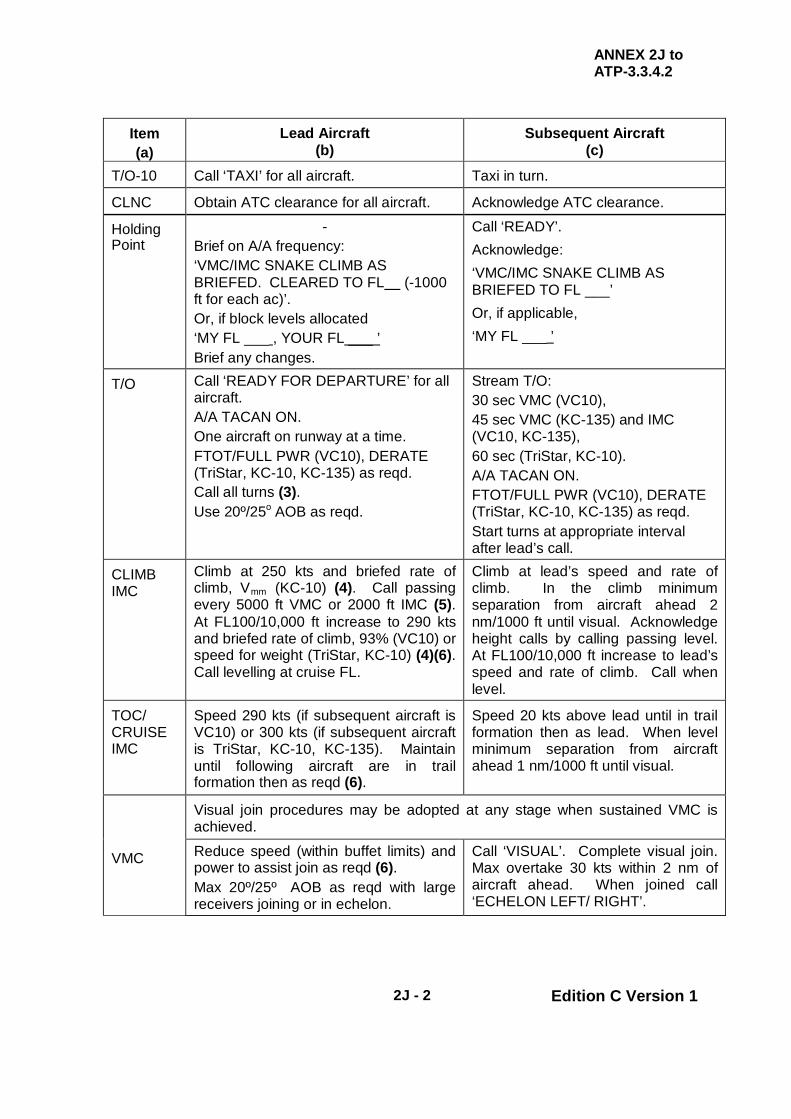
ANNEX 2J to ATP-3.3.4.2
2J - 2 Edition C Version 1
Item (a)
Lead Aircraft (b)
Subsequent Aircraft (c)
T/O-10 Call ‘TAXI’ for all aircraft. Taxi in turn.
CLNC Obtain ATC clearance for all aircraft. Acknowledge ATC clearance.
Holding Point
- Brief on A/A frequency: ‘VMC/IMC SNAKE CLIMB AS BRIEFED. CLEARED TO FL (-1000 ft for each ac)’. Or, if block levels allocated ‘MY FL ___ , YOUR FL ___ ’ Brief any changes.
Call ‘READY’. Acknowledge: ‘VMC/IMC SNAKE CLIMB AS BRIEFED TO FL ___’ Or, if applicable, ‘MY FL ___ ’
T/O Call ‘READY FOR DEPARTURE’ for all aircraft. A/A TACAN ON. One aircraft on runway at a time. FTOT/FULL PWR (VC10), DERATE (TriStar, KC-10, KC-135) as reqd. Call all turns (3). Use 20º/25o AOB as reqd.
Stream T/O: 30 sec VMC (VC10), 45 sec VMC (KC-135) and IMC (VC10, KC-135), 60 sec (TriStar, KC-10). A/A TACAN ON. FTOT/FULL PWR (VC10), DERATE (TriStar, KC-10, KC-135) as reqd. Start turns at appropriate interval after lead’s call.
CLIMB IMC
Climb at 250 kts and briefed rate of climb, Vmm (KC-10) (4). Call passing every 5000 ft VMC or 2000 ft IMC (5). At FL100/10,000 ft increase to 290 kts and briefed rate of climb, 93% (VC10) or speed for weight (TriStar, KC-10) (4)(6). Call levelling at cruise FL.
Climb at lead’s speed and rate of climb. In the climb minimum separation from aircraft ahead 2 nm/1000 ft until visual. Acknowledge height calls by calling passing level. At FL100/10,000 ft increase to lead’s speed and rate of climb. Call when level.
TOC/ CRUISE IMC
Speed 290 kts (if subsequent aircraft is VC10) or 300 kts (if subsequent aircraft is TriStar, KC-10, KC-135). Maintain until following aircraft are in trail formation then as reqd (6).
Speed 20 kts above lead until in trail formation then as lead. When level minimum separation from aircraft ahead 1 nm/1000 ft until visual.
VMC
Visual join procedures may be adopted at any stage when sustained VMC is achieved.
Reduce speed (within buffet limits) and power to assist join as reqd (6). Max 20º/25º AOB as reqd with large receivers joining or in echelon.
Call ‘VISUAL’. Complete visual join. Max overtake 30 kts within 2 nm of aircraft ahead. When joined call ‘ECHELON LEFT/ RIGHT’.

ANNEX 2J to ATP-3.3.4.2
2J - 3 Edition C Version 1
NOTES:
1 Timings for RT checks, start and taxi should be stated by the lead tanker. Standard timings are: RT check at T/O-40, start at T/O-20, taxi at T/O-10 (or when all ac ‘READY’). These timings may be varied to take account of local conditions. 2 If a VC10 and TriStar/KC-10 carry out a snake/formation climb, even if the TriStar/KC-10 is subsequently to lead the formation, the VC10 should lead the snake/formation climb. This will reduce problems of wake turbulence during the take-off and allow the TriStar/KC-10 to use its climb performance to best advantage. A KC-135 can be either lead or a subsequent aircraft. Any lead change should be carried out after join up. The following must be considered at the briefing stage:
a. Differences in rates of climb if there are large AUW or performance differences between aircraft.
b. IAS discrepancies caused by PEC differences. 3 Call all turns using the format ‘C/S TURNING LEFT/RIGHT XXX (hdg) NOW’ and commence the turn on executive word ‘NOW’, except for turns on a published SID which need not be called. 4 Details of the different climb parameters for each tanker are as follows:
a. The VC10 and KC-135 snake/formation climb speeds are 250 kts to FL100, then 290/0.82M (VC10K) or 290/0.84M (VC10C) or 280/0.78M (KC-135). However, a heavy VC10 may require a higher speed up to FL100 (1.35g buffet speed at FL100 at max AUW with aileron upset applied is 279 kts for a K2 and 268 kts for a K3/K4). If 250 kts is to be exceeded below FL100, ATC should be informed.
b. The recommended climb schedule for a TriStar is 250/300/0.80 if below 185,000 kg AUW and 250/320/0.82 if at or above 185,000 kg AUW. TriStar should have CLIMB 1 selected on the FMS when leading or following with TM engaged and CLIMB 3 displayed if following and using manual throttles.
c. Climb speeds for the KC-10 are normally 250/330/0.82M for aircraft less than 430,000 lbs Gross Wt. Above 430,000 lbs, the KC-10 climbs at Vmm to 10,000 ft then 330 KIAS/0.82M. For mixed KC-10/KC-135 formations, climb speeds are 285 KIAS with KC-10s less than 500,000 lbs and 310 KIAS for KC-10s equal to or greater than 500,000 lbs, unless a slower speed is required for an aircraft with more limiting performance.
5 In VMC, call height passing at least every 5000 ft until subsequent aircraft are visual. More frequent height calls should be given if there are large AUW or performance differences between aircraft, or if there are more than 2 aircraft in the snake climb. In IMC, call height passing every 2000 ft. 6 Call all speed changes.

ANNEX 2J to ATP-3.3.4.2
2J - 4 Edition C Version 1
INTENTIONALLY BLANK

ANNEX 2K to ATP-3.3.4.2
2K - 1 Edition C Version 1
CHAPTER 2 FIXED WING PROCEDURES ANNEX 2K AAR FORMATION PROCEDURES – HEAVY AIRCRAFT
2.K.1. AAR FORMATION PROCEDURES – HEAVY AIRCRAFT
a. Departure. For formation departure and join-up prior to air refuelling, comply with applicable national formation directives.
NOTE
NORMALLY, TANKERS WILL MAINTAIN EN-ROUTE FORMATION WHILE IN THE ORBIT PATTERN (SEE FIGURE 2K-1).
b. En-Route Formation. During the final turn to AAR track, tankers will adjust from en-route formation to 60o
right echelon with 2 nm nose-to-nose separation (1 nm for fighters) and stack up at 500-ft intervals (see figure 2K-2). Unless otherwise briefed, this formation will be used during the air refuelling operation. Pilots will use their radar scopes, A/A TACAN and TCAS to maintain the formation position.
Figure 2K-1. Diagram of En-Route Formation
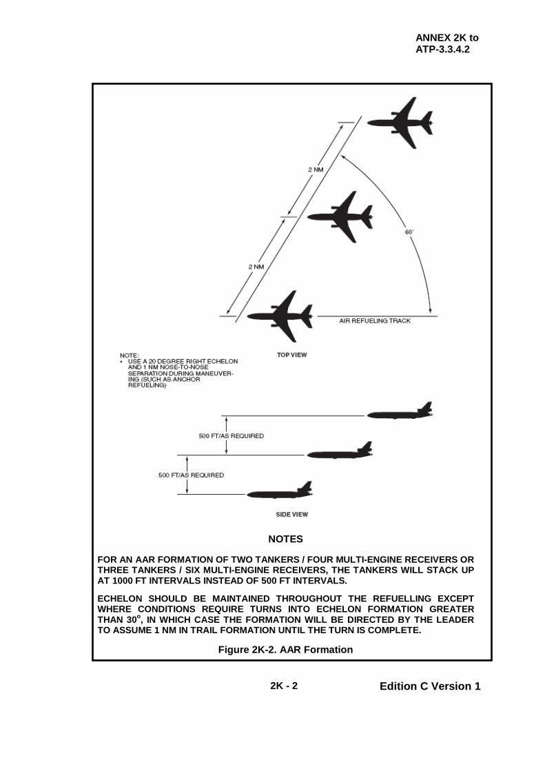
ANNEX 2K to ATP-3.3.4.2
2K - 2 Edition C Version 1
NOTES
FOR AN AAR FORMATION OF TWO TANKERS / FOUR MULTI-ENGINE RECEIVERS OR THREE TANKERS / SIX MULTI-ENGINE RECEIVERS, THE TANKERS WILL STACK UP AT 1000 FT INTERVALS INSTEAD OF 500 FT INTERVALS. ECHELON SHOULD BE MAINTAINED THROUGHOUT THE REFUELLING EXCEPT WHERE CONDITIONS REQUIRE TURNS INTO ECHELON FORMATION GREATER THAN 30o, IN WHICH CASE THE FORMATION WILL BE DIRECTED BY THE LEADER TO ASSUME 1 NM IN TRAIL FORMATION UNTIL THE TURN IS COMPLETE.
Figure 2K-2. AAR Formation

ANNEX 2K to ATP-3.3.4.2
2K - 3 Edition C Version 1
2.K.2. AAR FORMATION PROCEDURES TO BE USED BY USAF HEAVY
RECEIVERS
a. General. The receiver formation will move into AAR formation upon completion of the RV or as prebriefed. AAR formation is defined as 60° right echelon stacked up at 500 ft intervals with 1 nm nose-to-nose separation (see figure 2K-3). Nose to nose separation may be increased to match tanker air refuelling formations.
Figure 2K-3. AAR Formations – Heavy Receivers
AAR FORMATION (ONE TANKER/TWO OR MORE RECEIVERS)
AAR FORMATION (TWO TANKERS/ONE RECEIVER)
ANNEX 2K to ATP-3.3.4.2
2K - 4 Edition C Version 1
b. One Tanker/One Receiver
(1) Upon completion of AAR, the receiver will move aft and descend to a position at least 1000 ft below the tanker, and at least 1/2 nm in-trail.
(2) If unable to maintain visual contact with the tanker, increase
spacing to 1 nm. This position will be maintained until air refuelling is terminated and clearance is received from ARTCC.
(3) Prior to either aircraft departing the AAR formation, clearance
from ARTCC (US airspace) or ATC must be received and the tanker and receiver must coordinate their respective separation manoeuvres (verbal coordination not applicable during EMCON 3 and EMCON 4).
c. One Tanker/Two Receivers
(1) Receiver number 2 will maintain the AAR formation position (60o
right echelon stacked up 500 ft from the tanker) until refuelling is complete for the lead receiver.
(2) At that time, the lead receiver will descend 1500 ft, move aft and
left to assume a 60o left echelon, 2 nm nose-to-nose separation
from the refuelling element, stacked down at 1500 ft. (3) Once receiver lead is established in this post AAR position and
calls "established in post AAR", receiver number 2 will establish radio contact with the tanker and close by descending, then moving left (10o
or less of heading change), until established in a position 500 ft below and 1/2 nm in trail of the tanker.
(4) After receiver number 2 has completed refuelling, it will
manoeuvre directly aft while descending 1000 ft below the tanker (500 ft above receiver lead) call level at their altitude, decelerate, and rejoin on receiver lead (verbal coordination not applicable during EMCON 3 and EMCON 4).
(5) If needed, the tanker will then climb (or the receiver element may
descend) to an altitude which provides a minimum of 1000 ft between the tanker and the highest receiver.
(6) Prior to any aircraft departing the AAR formation, 1000 ft of
altitude separation between the tanker and highest receiver should be established (500 minimum required), clearance from ARTCC (US only) or ATC must be received, and the tanker and receivers must coordinate their respective separation manoeuvres (verbal coordination not applicable during EMCON 3 and EMCON 4).

ANNEX 2K to ATP-3.3.4.2
2K - 5 Edition C Version 1
d. Two or More Tankers/One Receiver
(1) During final turn to the AAR track, the tanker formation will move into echelon formation on the right of the tanker leader, stacked up at 500 ft intervals with 2 nm nose-to-nose separation measured along the 60o
echelon (see figure 2K-3). (2) The receiver will rendezvous with the lead tanker. When reaching
2 nm from the last tanker, and visual contact is established, the receiver will manoeuvre to refuel from the last tanker.
(3) After completion of this refuelling, the receiver will descend, then
manoeuvre left (10o or less of heading change), until established
in a position 500 ft below and 1/2 nm in trail of the next tanker (as necessary).
(4) Upon completion of this air refuelling, the receiver will move aft
and descend to a position at least 1000 ft below the lead tanker, and at least 1/2 nm in-trail.
(5) If unable to maintain visual contact with the lead tanker, increase
spacing to 1 nm. (6) This position will be maintained until air refuelling is terminated
and clearance is received from ARTCC (US only) or ATC. (7) Prior to any aircraft departing the air refuelling formation, 1000 ft
of altitude separation between the lowest tanker and the receiver should be established (500 ft minimum required), clearance from ARTCC must be received, and all tankers and receivers must coordinate their respective separation manoeuvres (verbal coordination not applicable during EMCON 3 and EMCON 4).
e. Three Tankers/Two Receivers
(1) A minimum of 4 successive altitudes (3000 ft) is required for this
procedure. (2) Planned fuel onload figures may vary depending on the mission. (3) For three tankers/two receivers, the receiver leader will refuel
from tanker number 2 first, receiving 1/3 of the scheduled onload. (4) The receiver leader will then descend and then move left to refuel
off the lead tanker, receiving the other 2/3 onload. (5) Receiver number 2 will refuel from tanker number 3 first,
receiving 2/3 of the scheduled onload.

ANNEX 2K to ATP-3.3.4.2
2K - 6 Edition C Version 1
(6) Receiver number 2 will then descend and then move left to refuel off tanker number 2, receiving the 1/3 of the scheduled onload (after the lead receiver has cleared tanker number 2).
(7) When the lead receiver has completed refuelling, it will clear the
lead tanker by descending, moving aft and left to assume a 60o
left echelon, 2 nm nose-to-nose separation from the refuelling element, stacked down 1500 ft.
(8) Once the lead receiver is established in this post AAR position,
the crew will call "Established in Post A/R." (9) After receiver number 2 has completed refuelling, it will descend,
move directly aft while descending 1500 ft below tanker number 2 (500 ft above receiver lead), call level at their altitude, decelerate, and rejoin on receiver lead (verbal coordination not applicable during EMCON 3 and EMCON 4).
(10) If needed, the tankers will then climb (or the receiver element
may descend) to an altitude which provides a minimum of 1000 ft between the lowest tanker and the highest receiver.
(11) Prior to any aircraft departing the air refuelling formation, 1000 ft
of altitude separation between the lowest tanker and highest receiver should be established (500 ft minimum required), clearance from ARTCC (US only) or ATC must be received, and all tankers and receivers must coordinate their respective separation manoeuvres (verbal coordination not applicable during EMCON 3 and EMCON 4).
f. Two Tankers/Three Receivers
(1) A minimum of 4 successive altitudes (3000 ft) is required for this
procedure. (2) Planned fuel onload figures may vary depending on the mission. (3) The receiver leader will receive the total scheduled onload from
the lead tanker. (4) Receiver number 2 will receive 1/2 the scheduled onload from
tanker number 2 and 1/2 the scheduled onload from the lead tanker.
(5) Receiver number 3 will receive the total scheduled offload from
tanker number 2. Receiver number 3 will maintain the air refuelling formation (60o
right echelon stacked up 500 ft from the number 2 tanker) until receiver number 2 has completed refuelling with tanker number 2.
ANNEX 2K to ATP-3.3.4.2
2K - 7 Edition C Version 1
(6) After completing the onload, receiver lead will descend, move aft and left, and assume a 60o
left echelon, 2 nm nose-to-nose separation from the lead tanker, stacked down 2000 ft.
(7) Once the lead receiver is established in this post AAR position,
they will call "Established in Post A/R." (8) Receiver number 2 will refuel from tanker number 2 first,
receiving 1/2 of the scheduled onload. (9) Receiver number 2 will then descend and move left to refuel off
the lead tanker, receiving 1/2 of the onload (after the lead receiver has cleared the lead tanker).
(10) After receiver number 2 has completed refuelling with the lead
tanker receiver number 2 will descend 1500 ft below the lead tanker (500 ft above the receiver lead), call level at their altitude, decelerate, and rejoin on the lead receiver (verbal coordination not required during EMCON 3 and EMCON 4).
(11) Once receiver number 3 has completed refuelling with tanker
number 2, they will descend 1000 ft below the lead tanker (500 ft above the number 2 receiver), call level at their altitude, decelerate, and rejoin on the receiver element (verbal coordination not required during EMCON 3 and EMCON 4).
(12) If needed, the tankers will then climb (or the receiver element
may descend) to an altitude which provides a minimum of 1000 ft between the lowest tanker and the highest receiver.
(13) Prior to any aircraft departing the air refuelling formation, 1000 ft
of altitude separation between the lowest tanker and highest receiver should be established (500 ft minimum required), clearance from ARTCC (US only) or ATC must be received, and all tankers and receivers must coordinate their respective separation manoeuvres (verbal coordination not applicable during EMCON 3 and EMCON 4).
g. Post AAR Position. The post AAR position is defined as the 60o
left echelon position, 2 nm nose-to-nose separation from the lead tanker, stacked down with a minimum of 1000 ft separation between the lowest tanker and the highest receiver.

ANNEX 2K to ATP-3.3.4.2
2K - 8 Edition C Version 1
INTENTIONALLY BLANK

ANNEX 2L to ATP-3.3.4.2
2L - 1 Edition C Version 1
CHAPTER 2 FIXED WING PROCEDURES ANNEX 2L RECEIVER STATION KEEPING EQUIPMENT
(SKE) – AAR PROCEDURES 2.L.1. INTRODUCTION This annex provides amplified guidance for aircraft employing Station Keeping Equipment (SKE) to maintain separation. 2.L.2. PRE-FLIGHT BRIEFING Tanker aircrews will contact their respective SKE formation receiver aircrews prior to flight to ensure full understanding of the formation air refuelling procedures to be used. 2.L.3. FORMATION SIZE AND DIMENSIONS
a. Normal Formation. The normal SKE formation consists of elements of three aircraft which fly co-altitude, 4000 ft in-trail from each other, 500 ft right for the number two aircraft, 500 ft left for the number three aircraft (Figure 2L-1).
b. Maximum Formation Size. Formations may consist of up to ten
elements of three aircraft. Each element will stack-up 100 ft above the preceding element. Tanker formations conducting refuelling operations with SKE formations will fly 60o
right echelon, 1 nm spacing, stacked up 500 ft (Figure 2L-1).
2.L.4. RENDEZVOUS Plan normal rendezvous procedures (en-route or point parallel). The following detailed tactics will be used when refuelling large formations of receiver aircraft utilising SKE:
a. Receiver formations utilising SKE procedures will use normal AAR Formation Procedures with minor modifications.
b. At the completion of the rendezvous, receiver formations will transition to
a right 60o echelon refuelling formation.
c. Receivers awaiting an open tanker will maintain the Awaiting AAR
Position. (Exception: The number three receiver when operating with a single tanker will remain in line with the number two receiver until the number two receiver transitions to the astern position).
d. Awaiting AAR Position. The Awaiting AAR Position is defined as right
60o echelon off the last tanker, 1 nm nose to nose spacing, stacked 500
ft above that tanker. Receivers in the Awaiting AAR Position will be cleared to their tanker after the preceding receiver calls "RECEIVER (NUMBER) ESTABLISHED IN POST AAR."

ANNEX 2L to ATP-3.3.4.2
2L - 2 Edition C Version 1
e. Change in Formation Constitution. Procedures, including spacing to
be used, will be briefed to tanker and receiver crews prior to flight. If the formation ratio changes (loss of a tanker or receiver through unserviceability, add-on tanker or receiver, etc.), in-flight coordination is required prior to the rendezvous.
2.L.5. POSITIVE SEPARATION It is the responsibility of all formation members (both tanker and receiver) to ensure positive separation throughout refuelling operations. Formation members shall know and understand where all formation members are at all times. Question any manoeuvre or position which you do not understand. 2.L.6. UNPLANNED TURNS If an unplanned turn must be accomplished (i.e. weather), tankers must coordinate with receivers well in advance of the turn. Lead tanker will announce turn direction and approximate roll out heading on AAR primary. All receivers must acknowledge before the turn may commence. Receiver acknowledgement indicates there is proper separation (see definition below) between all receivers and tankers and proper separation will be maintained throughout the turn. If a receiver cannot maintain proper separation, he will call:
"RECEIVER (NUMBER), STANDBY TURN"
Tankers will maintain current heading until Receiver (number) can maintain proper separation and calls:
"RECEIVER (NUMBER), READY FOR TURN" 2.L.7. SEPARATION CRITERIA Proper separation is defined as one of the following:
a. Established in post-AAR. b. Established in awaiting-AAR. c. Established or approaching (within 0.5 nm) the astern or contact
position. d. 500 ft altitude separation and 0.5 nm lateral separation being attained
and maintained from each tanker and receiver. 2.L.8. TURNS GREATER THAN 90 DEGREES Before executing turns greater than 90o, tankers must be in trail formation and receivers must be in a SKE in-line formation at least 1000 ft below the lowest tanker. Awaiting AAR receivers will not depart the Awaiting AAR Position toward the contact position until the:
ANNEX 2L to ATP-3.3.4.2
2L - 3 Edition C Version 1
"RECEIVER (NUMBER) ESTABLISHED IN POST AAR"
call is received. Before moving from the Awaiting AAR Position, that receiver will verify the previous receiver is clear of the intended flight path to the previous receiver calls:
"RECEIVER (NUMBER) CLEAR"
the receiver in the Awaiting AAR Position will establish radio contact with his respective tanker, and be cleared to astern position using normal closure procedures. 2.L.9. FORMATION IRREGULARITIES Any crewmember noting a formation position irregularity which may involve conflicting flight paths will immediately notify the pilot flying who will take action to prevent such conflict (roll out of closure heading, cease climb or descent, etc.) and establish radio contact with the other aircraft to de-conflict the situation. 2.L.10. TANKER ECHELON Tankers will maintain a precise 60o
right echelon formation position when refuelling with SKE formations. Precise formation position is more important than maintaining a smooth platform.
NOTE
WHEN REFUELLING SKE FORMATIONS, CREWMEMBERS SHOULD SHORTEN INDIVIDUAL TACTICAL CALL SIGNS. TANKER LEAD IS "TANKER 1", RECEIVER LEAD IS "RECEIVER 1" AND SO ON.
2.L.11. CONDITIONS FOR 180 DEGREE TURNS ON TRACK Tanker/SKE Receiver formations may execute 180o
turns on tracks if all the following conditions are met (no later than 2 min prior to the turn):
a. Tankers are in-line formation. b. Receivers have rejoined in an in-line SKE formation and are maintaining
a position 2 nm in trail of the lead tanker around the turn. c. The highest receiver is at least 1000 ft below the lowest tanker.
2.L.12. FORMATION POST ROLL-OUT Upon roll-out on new base course, if further formation refuelling is desired, the receiver formation will transition to normal AAR formation refuelling position. Receivers may elect to use a SKE Box Pattern. If this option is used, tanker(s) will proceed to the ARCP and prepare for a second rendezvous (point parallel). Prior coordination is essential.
ANNEX 2L to ATP-3.3.4.2
2L - 4 Edition C Version 1
NOTES
SKE BOX PATTERN IS A SERIES OF TURNS, 90O OR LESS, INITIATED AT THE AIR REFUELLING EXIT POINT DESIGNED TO POSITION THE SKE FORMATION FOR A POINT PARALLEL RENDEZVOUS IN THE OPPOSITE DIRECTION. EXCEPTION: FOR 2 OR 3 RECEIVERS ON 1 TANKER ONLY; THE RECEIVER IN THE CONTACT/ASTERN POSITION MAY REMAIN IN THE CONTACT/ASTERN POSITION DURING THE TURN. THE OTHER RECEIVER(S) WILL MOVE TO THE IN-TRAIL POSITION FOR THE DURATION OF THE 180O TURN. IN-TRAIL AIRCRAFT WILL RETURN TO AWAITING A/R OR POST A/R, WHICHEVER IS APPROPRIATE, AFTER THE REFUELLING FORMATION IS RE-ESTABLISHED ON TRACK (AFTER THE TURN). THE RECEIVER IN THE CONTACT/ASTERN POSITION WILL REMAIN IN THE CONTACT/ASTERN POSITION UNTIL THE OTHER RECEIVER(S) IS RE-ESTABLISHED IN THE AWAITING A/R OR POST A/R POSITION.
2.L.13. POST SKE AAR At the completion of AAR, receiver aircraft will move to the Post AAR position to accomplish their rejoin. The Post AAR position is defined as 60o
left echelon, 2 nm nose to nose separation, stacked down 1000 ft off the lead tanker. For large formations, this may require several receivers to cross behind the tanker formation prior to the tankers' transition to en-route formation (see Figure 2L-3 and 2L-5).
NOTE
FOR POST AAR, TO TRANSITION BACK TO SKE FORMATION, CONSIDERATION MUST BE GIVEN TO THE AMOUNT OF TIME REQUIRED TO ACCOMPLISH THIS TRANSITION. THIS MAY TAKE UP TO 15 MINUTES. ONCE THE RECEIVER FORMATION IS CONFIRMED IN THEIR RESPECTIVE SKE POSITIONS, THE SKE FORMATION LEADER WILL CONFIRM POSITION WITH TANKER LEADER. UPON CONFIRMATION, THE TANKER FORMATION CAN MOVE TO THE IN-TRAIL FORMATION, STACKED UP 500 FT.
2.L.14. BREAKAWAY In the event of a breakaway, SKE receiver aircraft are limited to an altitude 500 ft below their respective tanker. 2.L.15. TYPICAL SKE FORMATIONS Figures 2L-1 through 2L-8 depict typical receiver AAR formations when using SKE equipment.
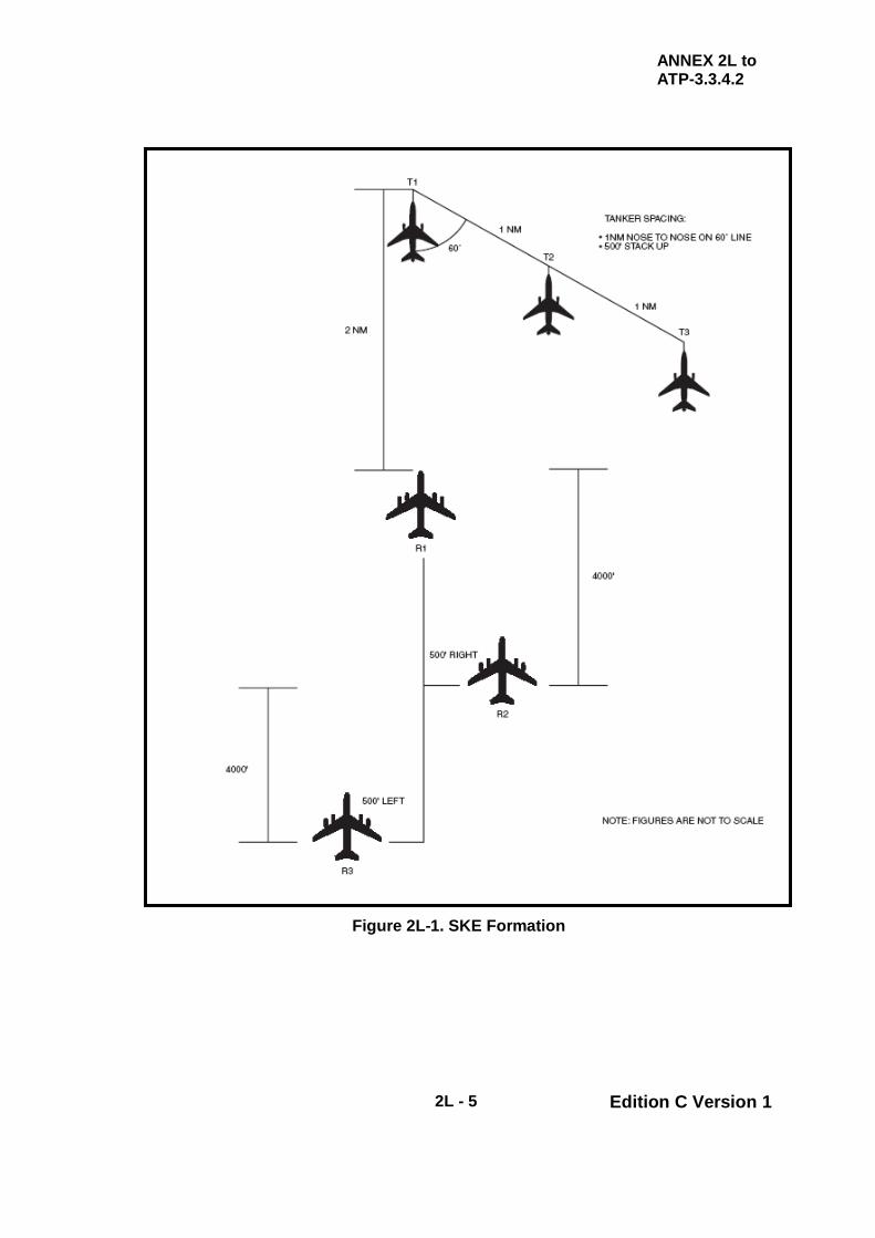
ANNEX 2L to ATP-3.3.4.2
2L - 5 Edition C Version 1
Figure 2L-1. SKE Formation

ANNEX 2L to ATP-3.3.4.2
2L - 6 Edition C Version 1
Figure 2L-2. AAR Procedures (3 Receivers (or 2) on 1 Tanker)

ANNEX 2L to ATP-3.3.4.2
2L - 7 Edition C Version 1
Figure 2L-3. Post AAR Procedures 3 Receivers (or 2) on 1 Tanker

ANNEX 2L to ATP-3.3.4.2
2L - 8 Edition C Version 1
Figure 2L-4. AAR Procedures (3 Receivers on 2 Tanker)

ANNEX 2L to ATP-3.3.4.2
2L - 9 Edition C Version 1
Figure 2L-5. Post AAR Procedures (3 Receivers on 2 Tankers)

ANNEX 2L to ATP-3.3.4.2
2L - 10 Edition C Version 1
Figure 2L-6. AAR Procedures (X Receivers on X Tankers)

ANNEX 2L to ATP-3.3.4.2
2L - 11 Edition C Version 1
Figure 2L-7. Post AAR Procedures (X Receivers on X Tankers)

ANNEX 2L to ATP-3.3.4.2
2L - 12 Edition C Version 1
Figure 2L-8. Post AAR Turns at End of Track

ANNEX 2M to ATP-3.3.4.2
2M - 1 Edition C Version 1
CHAPTER 2 FIXED WING PROCEDURES ANNEX 2M QUICK FLOW PROCEDURES
2.M.1. QUICK FLOW PROCEDURE (QF) (BOOM ONLY)
a. General. Fighter type receivers may use QF procedures to expedite AAR operations. QF allows receivers to minimize refuelling time with maximum fuel, but may be employed only during DAY or NIGHT under VMC conditions. If it appears that flight may result in penetration of adverse weather conditions, standard IMC procedures will be used. Co-ordination between tanker(s) and receivers is required prior to initiating QF procedures. Air tasking guidance, direct communication with the tanker unit or adding the term “Quick Flow” to the initial radio call will satisfy those co-ordination requirements. The Tanker lead is the final authority prior to initiating and during QF operations. Left echelon formation is normally used for QF; however, variations are authorized with prior tanker lead approval and flight lead co-ordination.
b. QF Procedures. Normally, the receiver flight will join on the tanker with
the flight lead moving to the astern position. Remaining aircraft will proceed to the Echelon Left, visual position. Once the flight lead commences refuelling, the second aircraft in the air refuelling sequence will move to the “On-Deck Position” (Figure 2M-1). The "On-Deck Position" is echelon formation on the receiver in the contact position. When the flight lead completes refuelling, that aircraft moves to an Echelon Right position on the tanker’s right wing. The second receiver moves from the “On-Deck Position” to the astern and contact position. If three or more receivers are part of the fighter formation, the third receiver moves to the “On Deck” position. The left to right flow continues until all fighters have refuelled. When AAR is complete, the aircraft will depart the tanker or remain in echelon formation on the tanker’s right wing for additional AAR. If further refuelling is required, reverse the above procedures with a right to left flow. The second receiver can assume a right "On Deck Position" and Quick Flow will continue in order. If additional receivers arrive prior to the first flights completion, they will remain in trail position until cleared by the tanker or observe the first flight departing the tanker.
c. Breakaway Procedures. In the event of a breakaway, the “On-Deck”
receiver follows the receiver on the boom. Any receivers on the wing will remain with the tanker. In the event a breakaway is initiated while a receiver is transitioning from the Echelon Left position to the “On- Deck” position, that receiver will follow the receiver on the boom.

ANNEX 2M to ATP-3.3.4.2
2M - 2 Edition C Version 1
Figure 2M-1. Quickflow Air Refuelling
2 "ON DECK"
1
4
3
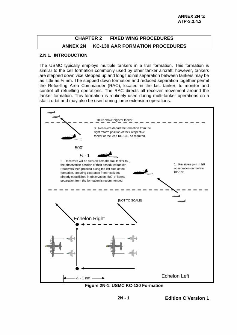
ANNEX 2N to ATP-3.3.4.2
2N - 1 Edition C Version 1
CHAPTER 2 FIXED WING PROCEDURES ANNEX 2N KC-130 AAR FORMATION PROCEDURES
2.N.1. INTRODUCTION The USMC typically employs multiple tankers in a trail formation. This formation is similar to the cell formation commonly used by other tanker aircraft; however, tankers are stepped down vice stepped up and longitudinal separation between tankers may be as little as ½ nm. The stepped down formation and reduced separation together permit the Refuelling Area Commander (RAC), located in the last tanker, to monitor and control all refuelling operations. The RAC directs all receiver movement around the tanker formation. This formation is routinely used during multi-tanker operations on a static orbit and may also be used during force extension operations.
Figure 2N-1. USMC KC-130 Formation
Echelon Right
1. Receivers join in left observation on the trail KC-130
[NOT TO SCALE]
3. Receivers depart the formation from the right reform position of their respective tanker or the lead KC-130, as required.
1000’ above highest tanker
500’
½ - 1 2. Receivers will be cleared from the trail tanker to
the observation position of their scheduled tanker. Receivers then proceed along the left side of the formation, ensuring clearance from receivers already established in observation. 500’ of lateral separation from the formation is recommended.
Echelon Left ½ - 1 nm

ANNEX 2N to ATP-3.3.4.2
2N - 2 Edition C Version 1
2.N.2. MULTI-TANKER RENDEZVOUS PROCEDURES The RVs employed by USMC KC-130s are the same as those for other tanker formations. RVs Alpha or Echo are used during static-orbit operations whilst, during force extension operations, the RV-Delta (Point Parallel) is the most common RV. 2.N.3. MULTI-TANKER FORMATION PROCEDURES
a. Receiver Join. Receivers joining a multi-tanker formation are to join in the Echelon Left position on the last tanker in the formation. Upon completion of the join, the receiver cruise formation is in echelon in the Echelon Left position. The tankers remain in the trail formation for all phases of refuelling.
(1) Receiver Tanker Assignment. When appropriate, receivers will
be cleared by the RAC to join their assigned tanker in the Echelon Left position. Receivers should anticipate receiving this clearance prior to stabilizing on the trail tanker.
(2) Receiver Joining Assigned Tanker. Once cleared, receivers
move along the left side of the tanker formation to the Echelon Left position of their assigned tanker. During this manoeuvre, receivers shall exercise caution and remain clear of other receivers already established in an Echelon Left position. A lateral separation of 500 ft from the tanker formation is recommended during this procedure.
b. Receiver Refuelling Flow
(1) Astern Position. Once receivers are established in the Echelon
Left position, the RAC will clear them to the astern position on the appropriate hose. Receivers should anticipate being directed to the right hose first, if available.
(a) Normally, receivers will not be directed behind an aircraft
already in contact with a refuelling hose. (b) Aircraft that are complete with refuelling on the left hose
will be directed to disconnect and remain in the astern position until the receiver in the right hose has disconnected.
(2) Clearance to Contact. Once established in the astern position,
receivers will be cleared to contact.

ANNEX 2N to ATP-3.3.4.2
2N - 3 Edition C Version 1
(3) Echelon Right Position. Once receivers are refuelling complete, they will be directed to disconnect and manoeuvre to the Echelon Right position of their respective tanker. With clearance from the RAC, the receiver flight lead may reform his entire flight in the Echelon Right position on the lead tanker. Receiver aircraft are to exercise caution and remain clear of other receivers already established in Echelon Right position when manoeuvring along the right side of the tanker formation.
(4) Leaving. When cleared to leave, receiver aircraft depart the
tanker formation either level or climbing. 2.N.4. COMMUNICATION PROCEDURES The terminology used during RT-controlled evolutions is standard. Receivers should be aware that the RAC, vice individual aircraft commanders, controls all receivers in the formation. During evolutions employing min-com or radio silent procedures, observers located in the paratroop doors of the KC-130 control receiver movement via aldis-lamp signals per Chapter 2 Annex2Q, Table 2Q-2. 2.N.5. PROCEDURES DURING IMC The stepped-down formation employed by the USMC poses a unique problem when receiver aircraft experience a “loss of visual contact”. In Chapter 2 Section IV, receivers in contact that lose sight of the tanker are instructed to initially descend 500 ft and reduce airspeed by 10 KIAS. Executing this procedure with a stepped-down formation creates a conflict between the receiver and the trailing tanker. To mitigate this hazard, the KC-130 formation should increase nose-to-tail separation to at least 1 nm. Additionally, receivers in contact that lose visual contact should climb 500 ft, vice descend 500 ft.

ANNEX 2N to ATP-3.3.4.2
2N - 4 Edition C Version 1
INTENTIONALLY BLANK

ATP-3.3.4.2
2 - 20 Edition C Version 1
CHAPTER 2 FIXED WING PROCEDURES SECTION III – ACCOMPANIED LET DOWN PROCEDURES
2.21. GENERAL It may occasionally be necessary for a tanker to accompany receiver aircraft from cruising level through a joint descent to a height of 500 ft AGL on the approach to a runway. The accompanied let down procedure provides a standard method of making a formation descent to a point from which a final approach and landing can be completed. 2.22. CRITERIA When considering the use of an accompanied let down, the following criteria should be used:
a. The procedure must be fully pre-briefed with particular regard to formation procedures, speeds, angles of bank and weather minima.
b. Aircraft limiting speeds for gear and flaps must not be exceeded. c. Single frequency approaches should be used whenever possible.
2.23. CONSIDERATIONS In addition to the criteria at para. 2.22. above, the following aspects should be considered:
a. The effect of wake turbulence, especially in strong crosswind conditions. b. At night or in IMC, reduced visibility may make formation flying difficult. c. Most receivers are sensitive to power changes, thus all tanker changes
in speed or power must be called early to prevent an overtake. d. Calls must be made when selecting services, on commencing descent
or go-around and for heading changes. e. Primary considerations for the tanker pilot must be smooth flying,
accurate airspeeds and the avoidance of rapid applications of bank. Bank angle is a particular consideration bearing in mind the long moment of the wing tip from the centreline. If the tanker autopilot is in use, it is advisable to disconnect it (if possible) from automatic lateral steering and height control facilities, to avoid unexpected and rapid deviations from a steady formation lead condition.

ATP-3.3.4.2
2 - 21 Edition C Version 1
2.24. STANDARD ACCOMPANIED LET DOWN Procedures unique to specific combinations of tanker and receiver types are covered in national instructions. However, on occasion a receiver(s) may require a let down led by a tanker from another NATO nation and in circumstances where pre-briefing or in-flight briefing is not possible. The following NATO Standard Accompanied Let Down should be used in these circumstances:
a. The tanker assumes responsibility for radio communication with the ground on behalf of the whole formation. The tanker navigates to the destination airfield or responds to ground directions.
b. When appropriate, the formation descends to FL100/10,000 ft at the
refuelling airspeed, avoiding high rates of descent. c. During the descent from FL100/10,000 ft to the runway instrument
pattern height, the formation progressively reduces speed to 200 KIAS. d. The tanker should request a runway instrument approach with, if
possible, a straight-in approach. e. At 3 nm or 500 ft AGL the tanker adopts the go around/overshoot
procedure, the receiver reduces to landing speed and lands.
NOTE
CONSIDER PROGRESSIVE SPEED REDUCTION TO BE AT 250 KIAS BY 10,000 FT (FOR FAA AND CANADIAN REGS).

ATP-3.3.4.2
2 - 22 Edition C Version 1
CHAPTER 2 FIXED WING PROCEDURES SECTION IV - SAFETY PROCEDURES
2.25. INTRODUCTION The foundation for the safe conduct of AAR by national or multi-national forces is standard, simple and unambiguous procedures. With these criteria established, multi-national AAR is practicable by day and night, and during periods of EMCON constraint. 2.26. RENDEZVOUS
a. Vertical Separation. Regardless of the method used to achieve a RV, it is vital to minimize collision risks by establishing a vertical separation between tanker and receiver; this vertical separation should be maintained until the receiver commences a visual join with the tanker.
b. Receiver Joining Tanker from Below. In some scenarios, prior to the
start of the RV procedure, the receiver may be cruising above the level of the tanker. Nevertheless, unless otherwise directed, and to achieve a commonality of practice, the receiver should descend and establish itself at least 1000 ft below the tanker before commencing the RV procedure. The cockpit view for receivers is usually better looking forward and upwards; moreover, a join from below allows the receiver greater freedom for manoeuvre with less risk of losing visual contact with the tanker.
c. Ultra Low Level AAR. In some circumstances (e.g. ultra low-level
AAR), a join from below may not be possible, in which case the tanker is to specify the exact nature of the join. If an RV is planned with a non-standard vertical separation, this should be specified in the tasking message, SPINS or at the briefing stage.
2.27. JOINING - SAFETY CONSIDERATIONS
a. Probe and Drogue Refuelling
(1) To complete a safe join, the receiver should achieve a stable formation position (i.e. zero rate of closure) on the tanker before manoeuvring to the astern position. Stable formation must be achieved in a position where an error of judgement in the join does not lead to a collision risk with the tanker.
(2) Longitudinal distance from the tanker and rate of closure from
behind are the most difficult features to assess, particularly at night; therefore, a direct join to a position behind the tanker should not be attempted.

ATP-3.3.4.2
2 - 23 Edition C Version 1
(3) Accordingly, all joins should be made to a loose echelon position in the Echelon Left position; thus errors in line and overtake speed can be corrected clear of the tanker.
b. Boom. Although receiver may join directly behind the boom, the
considerations described in para. 2.27.a.(1) applies equally to receivers joining a boom equipped tanker.
2.28. REFUELLING
a. Standardization. To achieve safe refuelling the standardised radio terms in Chapter 2 Annex 2P are to be used. A procedure for light signals to achieve safe radio silent AAR is at Chapter 2 Annex 2Q. However, it is recognised that not all NATO aircraft carry the necessary lights to fully implement these procedures at this time; national variations to light signals are contained in National SRDs.
b. Probe and Drogue AAR Over Land. AAR involves a small risk of parts
of the tanker’s/receiver’s AAR equipment detaching in-flight; broken probe nozzles are the most common occurrence and not all nozzles are retained in the tanker’s drogue coupling. Furthermore, on a few occasions, a tanker hose has separated from the aircraft. The civil population (and their property) should not be exposed to avoidable hazards; therefore routine AAR (including hose trail and wind) is not normally to take place over populated areas.
c. Trailing Hoses – Inadvertent Separation. If the tanker has not trailed
refuelling hoses before receiver join, the tanker will direct receivers to remain clear of the below and aft position of the refuelling hoses whilst the hoses are trailed. The majority of inadvertent hose departures (separation from the aircraft) from tankers occur during trailing or rewinding of refuelling hoses.
d. Trailing and Winding Hoses. If a tanker hose is trailed or wound when
the aircraft is not steady in straight and level flight, the hose may not feed correctly off or onto the hose drum; this could cause the hose to jam. The risk is small but can be easily avoided without significant operational penalties; therefore hoses:
(1) Are not to be moved during aircraft attitude changes. (2) Should only be wound during turns in cases of operational
necessity. (3) May be trailed and wound in a steady climb or descent. (4) May be trailed during a steady turn.

ATP-3.3.4.2
2 - 24 Edition C Version 1
e. Probe and Drogue Contacts and Disconnects. The rear viewing system of most multi-point tankers can only monitor the approach path to one wing hose at a time. Therefore, unless the tanker approves simultaneous receiver contact, the following guidelines should be adopted:
(1) Simultaneous AAR. For simultaneous AAR, one receiver is to
be in contact (with fuel flowing if wet) before the second receiver is cleared for contact.
(2) Simultaneous Disconnect. Normally, receivers will be cleared
to disconnect simultaneously. (3) Individual Receiver Disconnect. Receivers may be cleared to
disconnect individually if disparate fuel transfers exist. An individual disconnect may disturb the hose for the receiver remaining in contact; therefore, during receiver CONVEX, tankers may only order individual disconnects with the approval of the receiver leader or in the event of a spokes contact.
(4) Contacts/Disconnects – Straight and Level. There is
considerable potential for receiver pilot disorientation during AAR, particularly at night or when horizons are ill defined; this can be exacerbated by the wing anhedral/dihedral of some tankers giving false horizontal cues. Ideally, all contacts and disconnects should occur in straight and level flight, although by day experienced pilots may make contacts/disconnects in steady turns, climbs and descents providing the formation is clear of cloud and the drogues are stable.
(5) Prohibited Contacts/Disconnects. Contacts/disconnects are
not to be permitted during tanker attitude changes. (6) Contacts/Disconnects – CONVEX. Some nations require that,
during receiver CONVEX, tankers will order all contacts/disconnects in straight and level flight unless the receiver supervisory pilot requests otherwise for training purposes.
(7) Contacts/Disconnects – Night. By night, extra caution is
needed to guard against disorientation. Therefore, with due regard to prevailing visual conditions, the tanker may permit contacts and disconnects at night whilst in a steady turn/climb/descent. Where a receiver pilot subsequently elects to make contact or disconnect only in straight and level flight, they should, if possible, inform the tanker. Some nations will not permit night contacts or disconnects in a steady turn/climb/descent unless operationally necessary.
ATP-3.3.4.2
2 - 25 Edition C Version 1
f. Damaged Spokes. A receiver pilot damaging the spokes is to call ‘spokes’. If the probe has penetrated the drogue structure, the receiver pilot is to hold a stabilized in-contact position; the tanker is to order the receiver to ‘maintain position’. This will allow a controlled sequence of actions to minimize further damage to the tanker and receiver(s). When conducting multi-point simultaneous AAR, the tanker is then to order the unaffected receiver to disconnect and move to an echelon position. The affected receiver is then to be ordered to disconnect; the receiver is to disconnect in accordance with advice given in its own aircraft manual.
(1) Subsequent Actions - Tanker. Damaged spokes will impair the
structural integrity of the drogue so it is not to be used for further AAR. Before, a multi-point tanker continues AAR with its serviceable hose, tanker crews will follow tanker-specific procedures for the damaged hose.
(2) Subsequent Actions – Receiver. When spokes damage occurs,
the drogue may shed debris; and there is a significant probability of the receiver’s engine(s) ingesting the debris. When clear of the tanker, receiver pilots are to check engine instruments to assess possible damage, and if practical, have an airborne inspection to check for airframe damage. Receiver pilots are then to proceed as follows:
(a) Operational Sorties. Where operational considerations
are paramount, the sortie may be continued if there are no signs of engine or airframe damage. The receiver pilot is to advise the tanker accordingly.
(b) AAR Deployments. Where there are no signs of
damage, it may be preferable to continue with the deployment rather than embark on a long diversion to a foreign airfield where the aircraft may be grounded awaiting technical assistance. The receiver leader is to advise the tanker of the preferred course of action. The tanker is to assess the effect of the receivers’ wishes upon the safety of the formation; in particular, the implications of single hose AAR upon the overall plan are to be considered. The final decision on whether to continue or divert the formation (or part of it) rests with the tanker.
(c) Training/CONVEX Sorties. Experience shows that even
though there may be no indication to the receiver pilot of malfunction, engines sustain damage caused by ingestion of pieces of the drogue on 25% of all spokes contacts. Unless there are overriding reasons to continue the sortie, the safest course of action is to divert to the nearest suitable airfield.

ATP-3.3.4.2
2 - 26 Edition C Version 1
(3) After Landing. In all cases, the engine(s) of a receiver aircraft that has had a spokes contact is to be inspected after landing for possible damage.
g. Locked Receiver Nozzle. Exceptionally, it is possible that the receiver
probe nozzle may jam in the drogue reception coupling.
(1) If difficulty is experienced in disconnecting, the receiver pilot is to maintain a stabilized in-contact position; the tanker is to be informed so that the receiver on the other hose (if any) can be order to disconnect.
(2) When ordered by the tanker to disconnect, the receiver with the
jammed nozzle is to withdraw down the natural line of the hose; throttles may have to be fully retarded to achieve separation.
(3) Upon disconnect, the receiver is to immediately go to an echelon
position; parts of the probe and/or drogue may separate from the receiver and the tanker.
(4) The affected hose is not to be used for further AAR. (5) The receiver pilot is to proceed in accordance with the
instructions given in his aircraft manual.
h. Boom. The following warnings, cautions and notes are specific to boom AAR:
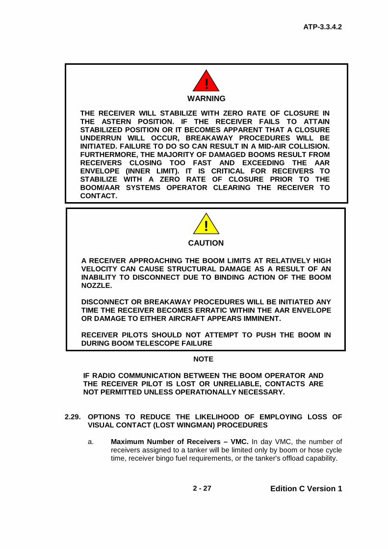
ATP-3.3.4.2
2 - 27 Edition C Version 1
NOTE
IF RADIO COMMUNICATION BETWEEN THE BOOM OPERATOR AND THE RECEIVER PILOT IS LOST OR UNRELIABLE, CONTACTS ARE NOT PERMITTED UNLESS OPERATIONALLY NECESSARY.
2.29. OPTIONS TO REDUCE THE LIKELIHOOD OF EMPLOYING LOSS OF
VISUAL CONTACT (LOST WINGMAN) PROCEDURES
a. Maximum Number of Receivers – VMC. In day VMC, the number of receivers assigned to a tanker will be limited only by boom or hose cycle time, receiver bingo fuel requirements, or the tanker's offload capability.
WARNING
THE RECEIVER WILL STABILIZE WITH ZERO RATE OF CLOSURE IN THE ASTERN POSITION. IF THE RECEIVER FAILS TO ATTAIN STABILIZED POSITION OR IT BECOMES APPARENT THAT A CLOSURE UNDERRUN WILL OCCUR, BREAKAWAY PROCEDURES WILL BE INITIATED. FAILURE TO DO SO CAN RESULT IN A MID-AIR COLLISION. FURTHERMORE, THE MAJORITY OF DAMAGED BOOMS RESULT FROM RECEIVERS CLOSING TOO FAST AND EXCEEDING THE AAR ENVELOPE (INNER LIMIT). IT IS CRITICAL FOR RECEIVERS TO STABILIZE WITH A ZERO RATE OF CLOSURE PRIOR TO THE BOOM/AAR SYSTEMS OPERATOR CLEARING THE RECEIVER TO CONTACT.
!
CAUTION
A RECEIVER APPROACHING THE BOOM LIMITS AT RELATIVELY HIGH VELOCITY CAN CAUSE STRUCTURAL DAMAGE AS A RESULT OF AN INABILITY TO DISCONNECT DUE TO BINDING ACTION OF THE BOOM NOZZLE. DISCONNECT OR BREAKAWAY PROCEDURES WILL BE INITIATED ANY TIME THE RECEIVER BECOMES ERRATIC WITHIN THE AAR ENVELOPE OR DAMAGE TO EITHER AIRCRAFT APPEARS IMMINENT. RECEIVER PILOTS SHOULD NOT ATTEMPT TO PUSH THE BOOM IN DURING BOOM TELESCOPE FAILURE
!

ATP-3.3.4.2
2 - 28 Edition C Version 1
b. Avoidance of Weather. If a tanker or receiver identifies flight conditions ahead of the formation (visually, using radar, reports from aircraft ahead or from ATC) that could result in one or more formation members losing visual contact with other formation members, the tanker should avoid the area using navigational turns and co-ordination with ATC.
c. Formation Entering Weather. In the event that the formation enters an
area of reduced visibility, the tanker should endeavour to maintain straight and level flight. If turns are necessary, they should be made using 10º AOB and called over the radio. In addition, the tanker will state the approximate roll out heading.
Tanker call: “(callsign) TURNING RIGHT, ROLLOUT HEADING 250.”
Tanker executes turn.
d. Formation Management
(1) Actions to Mitigate Risk of Loss of Visual Contact (Lost
Wingman). When inflight conditions are likely to impede safe operations of large formations on the wing of the tanker, the tanker and/or receiver formation lead should consider re-distributing receivers around the tanker. Such actions as restricting the number of receivers on a wing or moving some or all receivers into radar trail (provided that the lead receiver in each element is suitably equipped with a serviceable radar) should be considered.
(2) Large Receiver Formations. Nations have different definitions
of a “standard formation”. For instance, within the UK, a formation:
“is considered as a single unit for separation purposes provided that the formation elements are contained within one mile laterally and longitudinally and are at the same level.”
This contrasts with FAA regulations where:
“a “standard formation” is one in which a proximity of no more than 1 mile laterally or longitudinally and within 100 ft vertically from the flight leader is maintained by each wingman.”
In all cases, the formation leader is responsible for separation between units comprising the formation. This is known as MARSA – Military Accepts Responsibility for Separation of Aircraft. Also, whenever a tanker/receiver formation transits a nation’s airspace, the tanker (as the formation lead) must be aware of the formation regulations that govern that airspace and brief the receivers accordingly. Importantly, if the formation occupies or plans to occupy a volume of airspace (i.e.. vertically, horizontally or longitudinally) in excess of that defined by the
ATP-3.3.4.2
2 - 29 Edition C Version 1
Aeronautical Information Publications appropriate to the airspace, it is imperative that approval for using the additional airspace is obtained from the authority responsible for controlling the airspace.
(a) Formation Size – Night/IMC. During night and/or IMC,
the tanker/receiver formation lead should limit the size of the formation operating on the tanker. In such situations, normally, no more than 12 receivers will be in formation with a single tanker, with no more than 3 receivers in close formation on each wing (see para. 2.29.d.(2)(b)).
(b) Receivers on Tanker’s Wing – Night/IMC. Normally,
during night and/or IMC, the tanker should restrict the number of receivers in close formation with the tanker to a maximum of 6. These aircraft can be distributed with a maximum of 3 on each wing. Importantly, when a receiver is positioned astern of, or in contact with, a fuel transfer system, a wing position must be left vacant for each such receiver to accommodate the receiver(s) when refuelling is complete.
(c) Receivers in Trail. When the wing positions are full (to
include those positions reserved for receivers astern of, or in contact with, the fuel delivery system), other aircraft/elements should be directed to assume a trail position. The first element should be 1 to 1½ nm behind the tanker and stepped down 1000 ft below their tanker's altitude. The second trail element should be 1 to 1½ nm behind the first element and stepped down 1000 ft below the first element’s altitude, but see para. 2.29.d.(2) for ATC considerations.
(d) Large Formation – Receiver Distribution. During pre-
mission briefing for large formations, the tanker and formation lead should agree on a distribution plan for the receivers around the tanker in the event of night/IMC. Whilst numerous factors will help determine the most appropriate plan for a specific mission, Figure 2-6 illustrates one possible formation suitable for both boom and centreline hose receivers. Figure 2-7 offers a suggested formation for twin probe and drogue operations. In both cases, receivers are shown in the astern position; normally when not refuelling, these receivers will be positioned on the tanker’s wing.
(e) Receivers – Tanker Formations. For formations of
tankers, only the last tanker will have receivers in trail.

ATP-3.3.4.2
2 - 30 Edition C Version 1
(3) Additional Receivers – Joining (Night/IMC). In night and/or /IMC conditions, additional receivers should not be cleared to join the tanker when 3 receivers are already in both the Echelon Left and Echelon Right positions. Where less than 3 receivers are on a wing, additional receivers may be cleared to join that wing so long as they:
(a) Remain visual with the tanker and all receivers during the
join. (b) Join on the outside of the formation already on the wing. (c) The total number of receivers on a wing does not exceed
3.
(4) Tanker Management of Receivers. A large formation of up to 12 receivers against one tanker requires extensive coordination between the tanker and receiver formation lead. This is because there will be almost continuous receiver manoeuvring as receiver elements completing refuelling move aft and trailing elements move forward to the tanker's wing. To expedite this movement, the tanker should use the following procedures when directing the receiver aircraft.
(a) Tanker. The tanker should be in straight and level flight. (b) Tanker Manoeuvring for Weather. For tanker actions
when approaching weather see paras. 0229b. and 0229c. (c) Manoeuvring of Receiver Elements
(i) Element Moving Aft. The receiver element
moving to trail from the Echelon Left or Echelon Right position is to reposition first by moving aft and then down 500 ft.
(ii) Elements Moving Forward. The trailing elements
are not to move forward until lateral and vertical separation with the tanker and other receiver elements is confirmed using visual, radar, TCAS, A/A TACAN or other means.
(iii) Elements Leaving In-Trail Altitude. Elements
moving forward may only leave their in-trail altitude when:
(A) Visual with both the tanker and any
receiver elements between them and the tanker and able to remain clear of such elements when manoeuvring.
ATP-3.3.4.2
2 - 31 Edition C Version 1
Or
(B) Each in-trail element has confirmed and
deconflicted its longitudinal and vertical position with respect to the tanker and other receiver elements using visual, radar, TCAS, A/A TACAN or other means.
(iv) Element Closest to Tanker. Once paras.
0229d.(4)(c)(ii) and (iii) are satisfied, the element closest to the tanker may close to radar lock-on limits, or visual limits (as stipulated in Chapter 2 Section I) if radar is not working/fitted. Once visual with the tanker, the tanker may clear the element to close to the wing and/or boom as appropriate.
(v) Subsequent Trailing Element. Once the element
closest to the tanker has vacated its in-trail position, the next trailing element will move forward to 1nm to 1½ nm in trail of the tanker. Only when it has fulfilled the criteria paras. 0229d.(4)(c)(ii) and (iii), will the element climb to 1000 ft below the tanker’s altitude.
(vi) Descent of Element Moving Aft. The receiver
element moving to the trail position will continue to move aft to the last in-trail position at 500 ft below the tanker. Once the first and second elements have moved forward and are confirmed to be ahead of the element moving aft using visual, radar, TCAS, A/A TACAN or other means, the latter may descend to the appropriate in-trail altitude (1000 ft below the tanker if there is only one trail element or 2000 ft below the tanker if there are two trail elements).
(d) Tanker to Tanker RVs. During tanker-to-tanker RVs, the
tanker escorting the fighters should be at the lower altitude. If the escorting tanker is at the higher altitude, additional altitude separation between formations will be required.

ATP-3.3.4.2
2 - 32 Edition C Version 1
Figure 2-6. Night/IMC Formation Suitable for Both Boom and Centreline Hose Receivers

ATP-3.3.4.2
2 - 33 Edition C Version 1
Figure 2-7. Night/IMC Formations Suitable for Dual Probe and Drogue Receivers
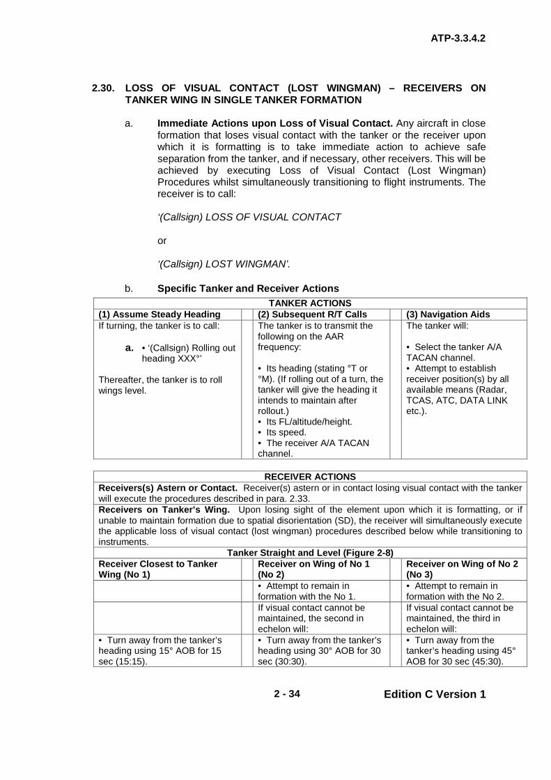
ATP-3.3.4.2
2 - 34 Edition C Version 1
2.30. LOSS OF VISUAL CONTACT (LOST WINGMAN) – RECEIVERS ON TANKER WING IN SINGLE TANKER FORMATION
a. Immediate Actions upon Loss of Visual Contact. Any aircraft in close
formation that loses visual contact with the tanker or the receiver upon which it is formatting is to take immediate action to achieve safe separation from the tanker, and if necessary, other receivers. This will be achieved by executing Loss of Visual Contact (Lost Wingman) Procedures whilst simultaneously transitioning to flight instruments. The receiver is to call:
‘(Callsign) LOSS OF VISUAL CONTACT or ‘(Callsign) LOST WINGMAN’.
b. Specific Tanker and Receiver Actions
TANKER ACTIONS (1) Assume Steady Heading (2) Subsequent R/T Calls (3) Navigation Aids If turning, the tanker is to call:
a. • ‘(Callsign) Rolling out heading XXX°’
Thereafter, the tanker is to roll wings level.
The tanker is to transmit the following on the AAR frequency: • Its heading (stating °T or °M). (If rolling out of a turn, the tanker will give the heading it intends to maintain after rollout.) • Its FL/altitude/height. • Its speed. • The receiver A/A TACAN channel.
The tanker will: • Select the tanker A/A TACAN channel. • Attempt to establish receiver position(s) by all available means (Radar, TCAS, ATC, DATA LINK etc.).
RECEIVER ACTIONS
Receivers(s) Astern or Contact. Receiver(s) astern or in contact losing visual contact with the tanker will execute the procedures described in para. 2.33. Receivers on Tanker’s Wing. Upon losing sight of the element upon which it is formatting, or if unable to maintain formation due to spatial disorientation (SD), the receiver will simultaneously execute the applicable loss of visual contact (lost wingman) procedures described below while transitioning to instruments.
Tanker Straight and Level (Figure 2-8) Receiver Closest to Tanker Wing (No 1)
Receiver on Wing of No 1 (No 2)
Receiver on Wing of No 2 (No 3)
• Attempt to remain in formation with the No 1.
• Attempt to remain in formation with the No 2.
If visual contact cannot be maintained, the second in echelon will:
If visual contact cannot be maintained, the third in echelon will:
• Turn away from the tanker’s heading using 15° AOB for 15 sec (15:15).
• Turn away from the tanker’s heading using 30° AOB for 30 sec (30:30).
• Turn away from the tanker’s heading using 45° AOB for 30 sec (45:30).

ATP-3.3.4.2
2 - 35 Edition C Version 1
• Resume the tanker’s heading to parallel track
• Resume the tanker’s heading to parallel track.
• Resume the tanker’s heading to parallel track.
Tanker Turning - Receiver on Outside of Turn (Figure 2-9) Receiver Closest to Tanker Wing (No 1)
Receiver on Wing of No 1 (No 2)
Receiver on Wing of No 2 (No 3)
• Attempt to remain in formation with the No 1.
• Attempt to remain in formation with the No 2.
If visual contact cannot be maintained, the second in echelon will:
If visual contact cannot be maintained, the third in echelon will:
• Turn away from the tanker by rolling through wings level to achieve 15° AOB in the opposite direction.
• Turn away from the tanker by rolling through wings level to achieve 30° AOB in the opposite direction.
• Turn away from the tanker by rolling through wings level to achieve 45° AOB in the opposite direction.
• Maintains this turn for 15 sec (15:15).
• Maintain this turn for 30 sec (30:30).
• Maintain this turn for 30 sec (45:30).
• Resume the tanker’s heading to parallel track. Tanker Turning - Receiver on Inside of Turn (Figure 2-10)
Receiver Closest to Tanker Wing (No 1)
Receiver on Wing of No 1 (No 2)
Receiver on Wing of No 2 (No 3)
• Attempt to remain in formation with the No 1.
• Attempt to remain in formation with the No 2.
If visual contact cannot be maintained, the second in echelon will:
If visual contact cannot be maintained, the third in echelon will:
• Momentarily reduce power to ensure nose-tail separation. • Roll into turn to achieve 15° AOB.
• Roll into turn to achieve 30° AOB.
• Roll into turn to achieve 45° AOB.
• Maintains this turn for 15 sec (15:15).
• Maintain this turn for 30 sec (30:30).
• Maintain this turn for 30 sec (45:30).
• Resume the tanker’s heading to parallel track.

ATP-3.3.4.2
2 - 36 Edition C Version 1
Figure 2-8. Loss of Wingman – Tanker Straight and Level
2
3
1
NOTE
This figure illustrates the approximate disposition of receivers and tanker after simultaneous loss of visual contact of the tanker / other receivers by each of 3 wingmen followed by the execution of the appropriate loss of visual contact action.

ATP-3.3.4.2
2 - 37 Edition C Version 1
Figure 2-9. Loss of Wingman – Receivers on Outside of Turn
2
3
1
NOTE
This figure illustrates the approximate disposition of receivers and tanker after simultaneous loss of visual contact of the tanker / other receivers by each of 3 wingmen followed by the execution of the appropriate loss of visual contact action. The tanker has rolled wings level on the first call of:
‘(Callsign) loss of visual contact’

ATP-3.3.4.2
2 - 38 Edition C Version 1
Figure 2-10. Loss of Wingman – Receivers on Inside of Turn
1
2
3
NOTE
This figure illustrates the approximate disposition of receivers and tanker after simultaneous loss of visual contact of the tanker / other receivers by each of 3 wingmen followed by the execution of the appropriate loss of visual contact action. The tanker has rolled wings level on the first call of:
‘(Callsign) loss of visual contact’

ATP-3.3.4.2
2 - 39 Edition C Version 1
c. Tanker Failure to Acknowledge. In either turning case, if the tanker
does not acknowledge the loss of visual contact call, the receiver is also to achieve an immediate vertical separation of 500 ft below tanker FL/altitude/height.
d. Tanker Climbing/Descending - Receivers. In addition to the actions
described in para. 2.30.b. above, when the tanker is climbing or descending, and where proximity to terrain is not a factor, the receiver(s) should level off whilst the tanker continues the climb/descent to the ATC cleared FL/altitude/height. The receiver must inform ATC of its level off FL/altitude/height either directly or through the tanker (see para. 2.30.f).
e. Lost Wingman with Fuel Transfer Complete. When a receiver
executes Loss of Visual Contact (Lost Wingman) procedures and fuel transfer is complete, it may decide to leave the tanker rather than execute a rejoin. In such circumstances the procedures outlined in Chapter 2, para. 2.10. should be modified as appropriate to the situation.
f. Informing ATC
(1) Receiver. If the receiver executing loss of visual contact (lost
wingman) procedure is working the ATC frequency, they are to inform ATC about their actions and seek an ATC service to rejoin the tanker/other receivers or depart.
(2) Tanker. Where the receiver is not working the ATC frequency,
the tanker is to relay the necessary safety information detailed in para. 2.30.f.(1) above.
g. Rejoin
(1) Vertical Separation. When initial lateral separation is achieved,
the receiver(s) is/are to achieve a vertical separation. (2) Longitudinal Separation. Separated receiver(s) is/are to use
radar/A/A TACAN/TCAS or other means to position 1 nm behind the last in-trail receiver element, so long as this does not conflict with the position of the next tanker in trail.
(3) Parameters to Rejoin Formation. Receivers will only attempt to
rejoin the formation when they can achieve the parameters described in Chapter 2, para. 2.2.d.
NOTES
NATIONAL SRD MAY STIPULATE DIFFERENT CRITERIA FROM THE ABOVE PROCEDURE (E.G. 20:20). IF MISSION REQUIREMENTS DICTATE, TANKER AND RECEIVER CREWS MUST AGREE DIFFERENCES TO ABOVE PROCEDURES PRIOR TO FLIGHT.

ATP-3.3.4.2
2 - 40 Edition C Version 1
2.31. LOSS OF VISUAL CONTACT (LOST WINGMAN) - MULTI-TANKER
FORMATION Depending on national policy, tankers will fly in both close and separated formation (e.g. echelon or trail). In the latter, the tankers will use a combination of visual positioning, electronic aids, radio transmissions and vertical separation to maintain the relative position between formation members.
a. Loss of Visual Contact – Tankers in Close Formation. For those nations that permit tankers to fly in close formation (see Figure 2-11), when visual contact is lost the Loss of Visual Contact Procedures (“Lost Wingman Procedures”) described in para. 2.30. is to be actioned, substituting tanker where reference is made to receiver(s).
Figure 2-11 – Tanker Close Formation
b. Loss of both Visual Contact and Situational Awareness – Separated Formation. Normally, in addition to visual monitoring, tankers in separated formation, both swept or trail, have many ways of maintaining situational awareness between all participating tankers. This includes air-to-air TACAN, weather radar, TCAS, radios, and vertical separation. If both visual contact and situational awareness are lost, the following procedures should be employed:
(1) Immediate Action by Tanker Losing Situational Awareness.
The tanker losing both visual and situational awareness will transmit:
“Callsign, LOST CONTACT”
(2) Achieving Vertical Separation. The tanker losing both visual
and situational awareness will coordinate with other tankers in the formation to ensure that vertical separation is achieved.
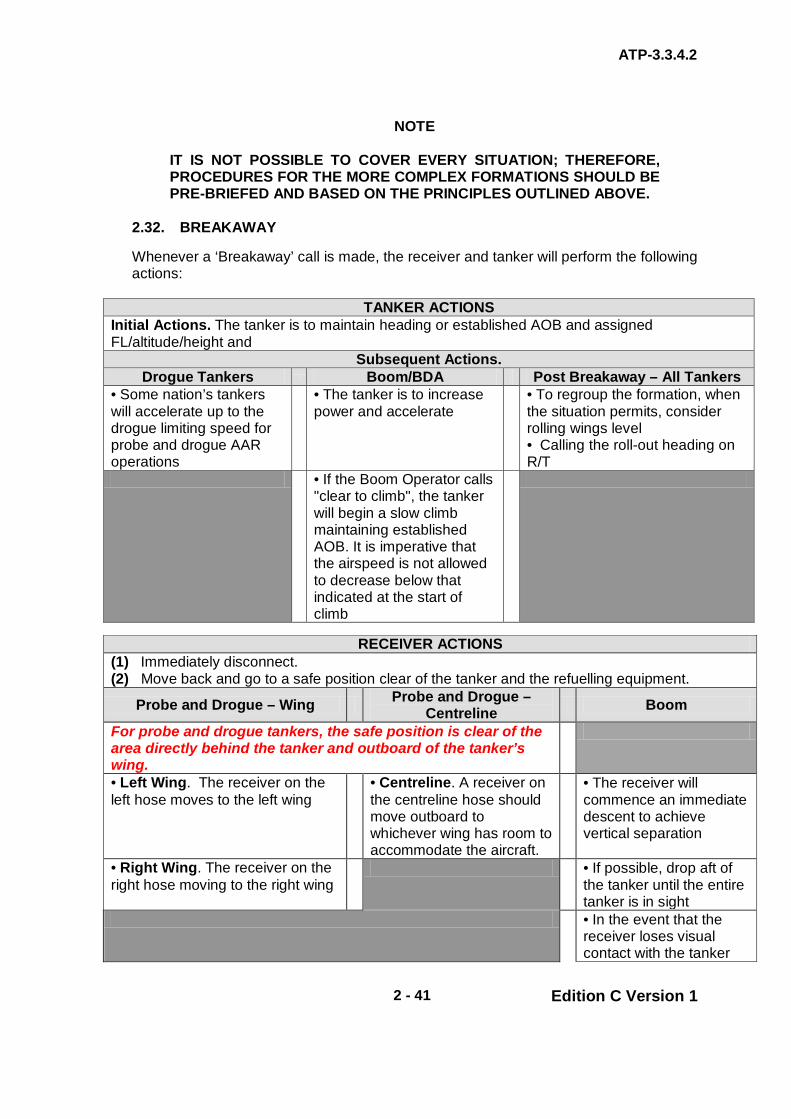
ATP-3.3.4.2
2 - 41 Edition C Version 1
NOTE
IT IS NOT POSSIBLE TO COVER EVERY SITUATION; THEREFORE, PROCEDURES FOR THE MORE COMPLEX FORMATIONS SHOULD BE PRE-BRIEFED AND BASED ON THE PRINCIPLES OUTLINED ABOVE.
2.32. BREAKAWAY Whenever a ‘Breakaway’ call is made, the receiver and tanker will perform the following actions:
TANKER ACTIONS Initial Actions. The tanker is to maintain heading or established AOB and assigned FL/altitude/height and
Subsequent Actions. Drogue Tankers Boom/BDA Post Breakaway – All Tankers
• Some nation’s tankers will accelerate up to the drogue limiting speed for probe and drogue AAR operations
• The tanker is to increase power and accelerate
• To regroup the formation, when the situation permits, consider rolling wings level • Calling the roll-out heading on R/T
• If the Boom Operator calls "clear to climb", the tanker will begin a slow climb maintaining established AOB. It is imperative that the airspeed is not allowed to decrease below that indicated at the start of climb
RECEIVER ACTIONS
(1) Immediately disconnect. (2) Move back and go to a safe position clear of the tanker and the refuelling equipment.
Probe and Drogue – Wing Probe and Drogue – Centreline Boom
For probe and drogue tankers, the safe position is clear of the area directly behind the tanker and outboard of the tanker’s wing.
• Left Wing. The receiver on the left hose moves to the left wing
• Centreline. A receiver on the centreline hose should move outboard to whichever wing has room to accommodate the aircraft.
• The receiver will commence an immediate descent to achieve vertical separation
• Right Wing. The receiver on the right hose moving to the right wing
• If possible, drop aft of the tanker until the entire tanker is in sight
• In the event that the receiver loses visual contact with the tanker

ATP-3.3.4.2
2 - 42 Edition C Version 1
RECEIVER ACTIONS during the breakaway: • Fighters: Descend at least 500 ft below the tanker • Heavy Receivers: Descend at least 1000 ft below the tanker
Breakaway Terminated. Once the breakaway is terminated, the receiver may either arrange with the tanker for a further closure or to depart. SAFETY NOTES: (1) Receivers waiting in echelon should remain in formation on the tanker. (2) Receivers waiting in echelon, as well as those executing a breakaway manoeuvre, are to exercise good lookout to prevent a receiver/receiver collision.
2.33. LOSS OF VISUAL CONTACT – RECEIVER(S) IN CONTACT OR ASTERN,
OR ASTERN FOLLOWING A BREAKAWAY
RECEIVER(S) Immediate Receiver Actions upon Loss of Visual Contact
Upon losing sight of the tanker, or if unable to maintain formation due to spatial disorientation (SD),a receiver(s) in contact or astern or following a breakaway will simultaneously: (1) Immediately disconnect (if appropriate). (2) Execute the applicable loss of visual contact (lost wingman) procedures described below while transitioning to instruments. (3) Make a call of:
• ‘(Callsign) loss of visual contact’ (4) Slow down 10kts
TANKER ACTIONS Initial Actions. The tanker is to maintain heading or established AOB and assigned FL/altitude/height and
Subsequent Actions
Drogue Tankers Boom/BDA Post Breakaway – All Tankers
• Some nation’s tankers will accelerate up to the drogue limiting speed for probe and drogue AAR operations
• The tanker is to increase power and accelerate
• To regroup the formation, when the situation permits, consider rolling wings level and calling the roll-out heading on R/T
• If the Boom Operator calls “clear to climb”, the tanker will begin a slow climb maintaining established AOB. It is imperative that the airspeed is not allowed to decrease below that indicated at the start of climb
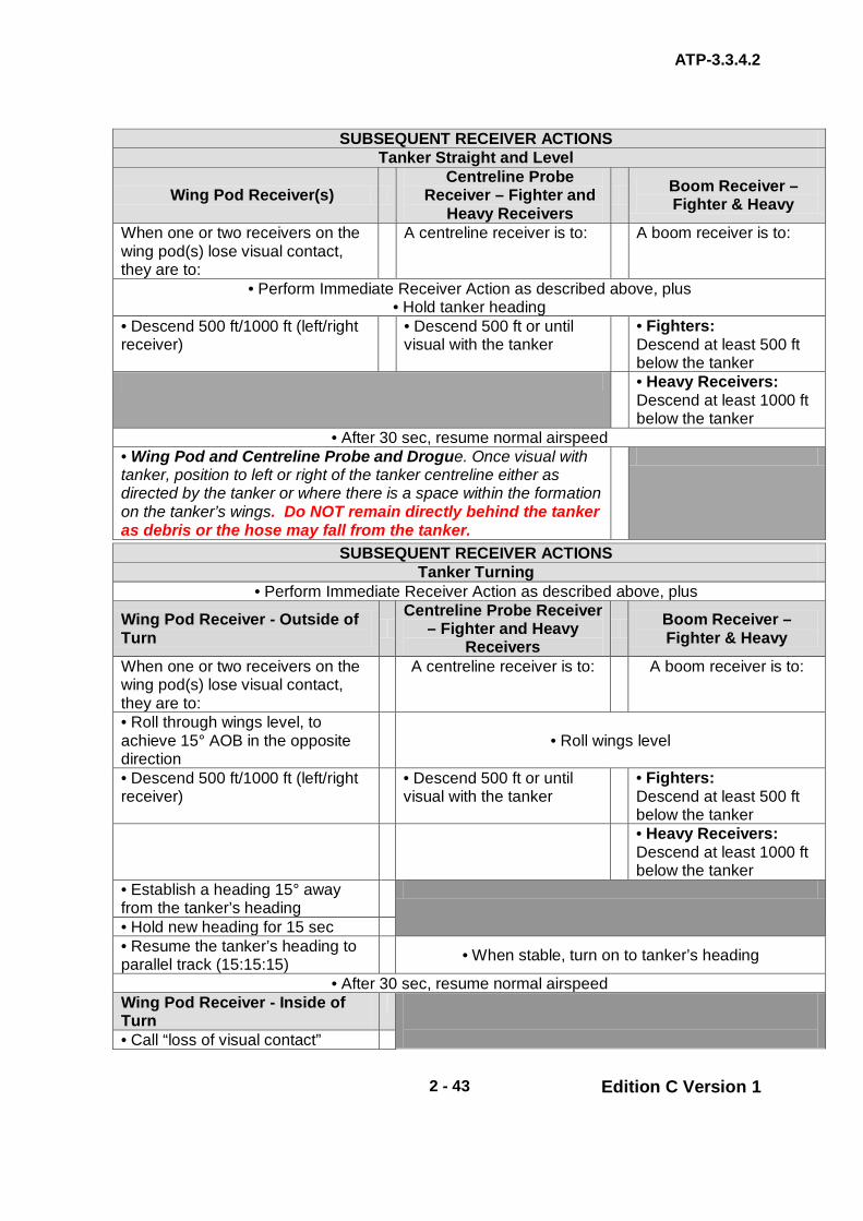
ATP-3.3.4.2
2 - 43 Edition C Version 1
SUBSEQUENT RECEIVER ACTIONS Tanker Straight and Level
Wing Pod Receiver(s) Centreline Probe
Receiver – Fighter and Heavy Receivers
Boom Receiver – Fighter & Heavy
When one or two receivers on the wing pod(s) lose visual contact, they are to:
A centreline receiver is to: A boom receiver is to:
• Perform Immediate Receiver Action as described above, plus • Hold tanker heading
• Descend 500 ft/1000 ft (left/right receiver)
• Descend 500 ft or until visual with the tanker
• Fighters: Descend at least 500 ft below the tanker
• Heavy Receivers: Descend at least 1000 ft below the tanker
• After 30 sec, resume normal airspeed • Wing Pod and Centreline Probe and Drogue. Once visual with tanker, position to left or right of the tanker centreline either as directed by the tanker or where there is a space within the formation on the tanker’s wings. Do NOT remain directly behind the tanker as debris or the hose may fall from the tanker.
SUBSEQUENT RECEIVER ACTIONS Tanker Turning
• Perform Immediate Receiver Action as described above, plus
Wing Pod Receiver - Outside of Turn
Centreline Probe Receiver – Fighter and Heavy
Receivers Boom Receiver –
Fighter & Heavy
When one or two receivers on the wing pod(s) lose visual contact, they are to:
A centreline receiver is to: A boom receiver is to:
• Roll through wings level, to achieve 15° AOB in the opposite direction
• Roll wings level
• Descend 500 ft/1000 ft (left/right receiver)
• Descend 500 ft or until visual with the tanker
• Fighters: Descend at least 500 ft below the tanker
• Heavy Receivers: Descend at least 1000 ft below the tanker
• Establish a heading 15° away from the tanker’s heading
• Hold new heading for 15 sec • Resume the tanker’s heading to parallel track (15:15:15)
• When stable, turn on to tanker’s heading
• After 30 sec, resume normal airspeed Wing Pod Receiver - Inside of Turn
• Call “loss of visual contact”

ATP-3.3.4.2
2 - 44 Edition C Version 1
• Simultaneously slow down 10 kts and
Maintain the turn until heading 15° away from the tanker’s heading
• Descend 500 ft/1000 ft (left/right receiver)
• Hold new heading for 15 sec • Resume the tanker’s heading to parallel track (15:15:15)
• After 30 sec, resume normal airspeed
• Wing Pod and Centreline Probe and Drogue. Once visual with tanker, position to left or right of the tanker centreline either as directed by the tanker or where there is a space within the formation on the tanker’s wings. Do NOT remain directly behind the tanker as debris or the hose may fall from the tanker.
Breakaway Terminated. Once the breakaway is terminated, the receiver may either arrange with the tanker for a further closure or to depart. SAFETY NOTES: 1. Receivers waiting in echelon should remain in formation on the tanker. 2. Receivers waiting in echelon, as well as those executing a breakaway manoeuvre, are to exercise good lookout to prevent a receiver/receiver collision.
2.34. LEAVING See Chapter 2, para. 2.10. 2.35. AIRCRAFT MALFUNCTION
a. A tanker or receiver emergency may require an urgent cessation of refuelling; in this event the radio call:
“(Tanker Callsign), BREAKAWAY, BREAKAWAY, BREAKAWAY”
and/or signal light command is to be given, see Chapter 2 Annexes 2P and 2Q.
b. The receiver is required to disconnect immediately and move clear of the
tanker, see paras. 0232 and 0233. The responsibility of achieving safe separation is placed on the receiver.
c. The tanker is to maintain heading. Also, the tanker is to maintain
FL/altitude/height or climb as required by national breakaway procedures. Additionally, some nation’s tankers will accelerate up to the drogue limiting speed for drogue AAR operation.
d. For boom/BDA operations, the tanker is to increase power and
accelerate.
ATP-3.3.4.2
2 - 45 Edition C Version 1
2.36. WAKE TURBULENCE Wake turbulence caused by wide-bodied (heavy) jets can affect a considerable area and precautions are necessary to ensure that AAR formations are not subject to disturbance whilst refuelling is in progress. If a contact is reported by radar or sighted visually, whose track will coincide with or cross within 10 nm of the track of an AAR formation and whose vertical position is within the 2000 ft band above the formation, the following action is to be taken:
a. Attempt to identify if the contact is ‘heavy’. b. If ‘heavy’ or if identity cannot be established. c. Order any receivers in contact to disconnect. d. Do not bring receivers into contact until affected track area has been
traversed.
NOTE
MULTI-TANKER FORMATIONS THAT INCLUDE TRISTAR/KC-10 SHOULD BE PARTICULARLY AWARE OF WAKE TURBULENCE, ESPECIALLY IF THE TRISTAR/KC-10 IS LEADING OR TAKES THE LEAD.
2.37. FUEL DUMP. On occasions, a tanker may have to dump fuel. The tanker pilot is to inform the national ATC agency that a ‘fuel dump’ is necessary and is to obtain permission from the ATC agency prior to dumping fuel. Many nations have designated fuel dump areas and, if possible, the tanker is to fly to this area before dumping fuel. 2.38. HOSE JETTISON If at all possible, hoses are to be jettisoned over the open sea, at least 20 nm from the coast. Some nations have reserved ordnance jettison areas; therefore, the tanker pilot is to advise the ATC agency of the need to jettison a hose and is to operate in accordance with the national ATC agency directions. Additionally, the tanker crew is to use all available means to ensure the area below the tanker is clear. This is best achieved by carrying out a visual search of the area below, if weather conditions and fuel reserves permit. If weather conditions and/or fuel reserves do not permit a visual search, then the hose may be jettisoned, under the directions of the national ATC agency, from the normal cruising FL/altitude/height. In this case, the tanker’s radar is to be used to check that the area is clear and the ATC agency is to confirm that the airspace beneath the tanker is clear of other aircraft. The position and time of release is to be logged and reported using an appropriate national Air Incident Report. Only in an emergency is the hose to be jettisoned over land. If the hose fails to jettison, the aircraft is to recover to land avoiding built up areas.

ATP-3.3.4.2
2 - 46 Edition C Version 1
2.39. RADAR AND WEAPONS It is the responsibility of the receiver aircraft commander to ensure that the aircraft radar is not radiating. Normally, the radar should be set to standby once the receiver is visual with the Tanker. Similarly, the receiver aircraft commander is to ensure that weapons are safe prior to commencing an RV with a tanker. During conditions of EMCON constraint (EMCONs 3 and 4), radio calls between tanker and receiver to check on radar and/or armament states are both inappropriate and impractical.

ATP-3.3.4.2
2 - 47 Edition C Version 1
CHAPTER 2 FIXED WING PROCEDURES SECTION V – COMMUNICATIONS
2.40. SECURITY It can be assumed that all AAR frequencies will be subject to regular monitoring by potentially hostile agencies. Message originators are to ensure that classified information is not passed in an unclassified form. In particular, messages concerning airframe numbers, linkage of squadrons and locations, order of battle and associations of personnel with units are not to be transmitted. Tanker transmissions are liable to be intercepted, thus giving hostile forces knowledge of tanker positions and procedures; therefore, transmissions must be kept to a minimum. It will also be necessary on occasion to restrict the use of some or all aircraft electronic transmitting equipment.
NOTE
DEPENDING ON THE EMCON CONDITIONS, SOME TANKER NATIONS MAY PERMIT OR MANDATE THE TRANSMISSION OF AIRCRAFT AIRFRAME NUMBERS IN ORDER TO TRACK FUEL TRANSFER. RECEIVER NATIONAL GUIDANCE MUST BE FOLLOWED BEFORE COMPLYING WITH SUCH REQUESTS.
2.41. COMMUNICATIONS IN MULTI-TANKER FORMATIONS The lead tanker crew is responsible for the formation communications. If special circumstances require, specific tasks may be delegated to other tankers in the formation. 2.42. HF TRANSMISSION RESTRICTIONS
a. Facilitating Join-up. HF radio communications during AAR is limited to situations when either the tanker/receiver combination is beyond UHF range or to facilitate join up for AAR if unable to make UHF contact.
b. Use of HF During AAR. No HF transmissions are to be made from a
tanker or receiver when a receiver is in contact or about to make contact and all HF equipment must be switched to STANDBY/MONITOR where possible.
NOTE
SOME RECEIVER AIRCRAFT HAVE FLIGHT CONTROL SYSTEMS WHICH ARE SUSCEPTIBLE TO HF TRANSMISSIONS. THEREFORE, THEY MAY REQUIRE A GREATER SEPARATION FROM THE TANKER BEFORE HF TRANSMISSIONS ARE MADE (EG TORNADO AIRCRAFT REQUIRE 1000 M / ½ NM SEPARATION BEFORE TANKER HF IS USED).

ATP-3.3.4.2
2 - 48 Edition C Version 1
2.43. IFF/SIF IFF/SIF is to be operated on all exercises/operations in accordance with the tasking order. If it is necessary to switch IFF to standby, the controlling unit is to be informed. 2.44. SEARCH AND RESCUE (SAR) AIRCRAFT On some Oceanic AAR flights, maritime patrol aircraft may be tasked to provide airborne SAR cover for a deployment. SAR aircraft should listen out on the briefed AAR frequency and monitor normal Oceanic frequencies for regular position reports. Where applicable, individual Mode 1 IFF settings should be allocated to all tankers and receivers to aid the SAR aircraft to track the formation(s). 2.45. AAR RADIO PROCEDURES
a. General. Control of receivers during routine AAR is achieved by radio commands given by the tanker. To assist interoperability, these commands are standardized, although mission/operation-specific requirements may be detailed in the tasking order. Importantly, to avoid uncertainty, normally, all RT calls will be prefaced with the speaking unit’s individual callsigns. Outside of the training arena, normal operations are conducted using EMCON 2 procedures. Therefore, radio communications should be kept to a minimum consistent with safety and the published EMCON option; excessive radio traffic is distracting to the receiver pilot and is a potential source of confusion. Regardless of the type of AAR equipment in use, only a basic set of commands is required to accomplish refuelling. These basic commands are listed at Chapter 2 Annex 2P.
b. Probe and Drogue. In general terms, the probe and drogue system
places the responsibility of positioning for refuelling on the receiver, after the tanker has cleared the receiver astern the refuelling equipment.
c. Boom. The boom system places more reliance on the tanker giving
positioning commands to the receiver and the boom interphone should be used rather than RT whenever possible.
d. Air-to-Air (A/A) TACAN
(1) To provide A/A TACAN ranging, the tanker and the receiver (one
aircraft per receiver and tanker formation) should tune the assigned A/A TACAN channels 15 min before the ARCT. The two designated channels will be 63 channels apart with the receiver setting the lower channel and the tanker the higher channel. The majority of receivers use the Y- channel but some only have X-channel capability.
(2) A/A TACAN should be left in the A/A setting until the receiver
reaches astern (boom) or the Echelon Left position (drogue).
ATP-3.3.4.2
2 - 49 Edition C Version 1
e. Monitoring Guard. During AAR , where radio equipment permits, tanker
crews must maintain a listening watch on 243.00 MHz; this provides a guard frequency for receivers that need to join a tanker but do not know the AAR control frequency. Furthermore, 243.00 MHz provides a guard frequency in the event of loss of radio contact between tanker and receiver.
f. Loss of RT Communication. Loss of radio communication between
tankers and receivers could prove hazardous, particularly during boom AAR. Receiver and tanker crews are to be aware of any national restrictions on the conduct of AAR when communications have been lost and are to operate in accordance with such instructions.
2.46. VERBAL COMMUNICATION – BOOM AAR ONLY Communication requirements should be established prior to the flight. Normally, boom visual signals will be used exclusively; however, if required or requested by the receiver, the boom operator will begin communications when the receiver reaches approximately 50 ft from the contact position. Direction, if required, will precede distance (in ft) for the receiver to move and will be given until the receiver reaches the contact position; example:
“FORWARD 50”, “UP 4”, “BACK 2”
When contact is established the tanker will state:
“(Tanker Callsign) CONTACT” For Emission Options 1 and 2, the boom operator will make a astern radio check with the receiver(s) and the receiver(s) will acknowledge; example: Tanker will say:
“25/57” The receiver will reply:
“25” 2.47. BOOM ENVELOPE DEMONSTRATIONS During receiver pilot demonstration of AAR envelope limits, the boom operator will state the limit and give the boom position for the limit being demonstrated in increments of “2” for roll/azimuth and elevation, and “1” for telescoping (These are "degrees" and "feet" respectively but the dimensions are not normally included in R/T transmissions). When tankers are not equipped with an Independent Disconnect System, prior to receivers demonstrating envelope limits, the boom operator is required to confirm that a boom operator-initiated disconnect occurred. In this instance, receivers shall not request an envelope limits demonstration on the first contact.

ATP-3.3.4.2
2 - 50 Edition C Version 1
2.48. MANUAL AND EMERGENCY BOOM LATCHING During tanker manual operation (without tanker disconnect capability) and emergency boom latching the following receiver briefings will be accomplished:
a. Tanker Manual Operation (TMO) Briefing (Without Tanker Disconnect Capability). During the briefing for tanker manual operation where there is no tanker disconnect capability, the boom operator will state:
“(Receiver Callsign), THE FOLLOWING CONTACTS WILL BE MADE IN TANKER MANUAL OPERATION WITHOUT TANKER DISCONNECT CAPABILITY. RECEIVER AIR REFUELLING SYSTEM WILL REMAIN IN NORMAL AND RECEIVER PILOT MUST INITIATE ALL DISCONNECTS.” “(Tanker Callsign), READY”
Receiver pilot acknowledges by stating:
“(Receiver Callsign) READY”
b. Emergency Boom Latching/Override Operation Briefing. During the
briefing for emergency boom latching/override operation, the boom operator will state:
“(Tanker Callsign), READY”
Receiver pilot will acknowledge by stating: “(Receiver Callsign), READY”
Tanker boom operator will state “(Receiver Callsign), THE FOLLOWING CONTACTS WILL BE MADE IN MANUAL BOOM LATCHING. THE RECEIVER MUST INITIATE ALL DISCONNECTS”
The receiver will acknowledge by stating: “(Receiver Callsign) ASTERN READY”
Tanker boom operator acknowledges by stating: “(Tanker Callsign), READY”

ATP-3.3.4.2
2 - 51 Edition C Version 1
2.49. FUEL TRANSFERRED At a convenient time between the receiver disconnecting and leaving the formation, the tanker should inform each receiver of the amount of fuel transferred. For boom interphone equipped tankers, the offload report may be made prior to disconnect. Whenever possible, the fuel quantity should be expressed in the units of measurement used by the receiver’s fuel system. 2.50. LOSS OF RADIO CONTACT If radio contact is lost between tanker and receiver on the allocated AAR frequency:
a. Attempts are to be made to re-establish contact on the secondary AAR frequency.
b. If contact is not established on the secondary frequency or one is not
allocated, both tanker and receiver are to establish contact on 243.00 MHz (121.50 MHz for some receivers).
c. Continued routine communication should not take place on the distress
frequency; therefore tanker and receiver should attempt to continue AAR communication on another mutually acceptable frequency.
d. Some receivers have only one main radio and a standby radio pre-tuned
to the distress frequency. If the loss of radio contact was caused by the failure of the receiver’s main radio, then AAR communication on the distress frequency will be necessary; nevertheless, this should be minimized and radio silent procedures should be adopted if possible.
2.51. EMISSION CONTROL PROCEDURES There may be a need to conduct AAR exercises/operations in electronic silence. The controlling authority will promulgate the emission control (EMCON) procedure in force for the exercise/operation. The use of electronic emitters will vary according to the assessed threat. The definition of each EMCON option is given in Chapter 2 Annex 2O. Also, EMCON options and acceptable communications for each option are shown in Chapter 2 Annex 2O. This describes 4 levels of restriction on the use of electronic emissions and provides for further refined selection of transmitters. 2.52. RADIO SILENT PROCEDURES There will be occasions when AAR is conducted using agreed procedures and signalling facilities without the use of radio. For pre-planned operational and training missions, the method, time and place of rendezvous, together with the amount of fuel to be transferred, must be covered in the pre-flight briefing of both the tanker and receiver crews. Radio silent procedures and visual boom signals are detailed in Chapter 2 Annex 2Q. The occasions requiring silent procedures are:
a. When called for by the EMCON policy in force.
ATP-3.3.4.2
2 - 52 Edition C Version 1
b. When deemed tactically necessary by the tanker or for training purposes agreed between tanker and receiver. In these cases, the tanker commander initiates the procedures by stating at the briefing stage or on radio at any time ‘silent procedures’.
c. In the event of radio failure. Refuelling following total radio failure should
only be undertaken when refuelling is essential due to the critical nature of the mission.
d. In the event that a receiver requires fuel but does not know the tanker’s
operating frequency. 2.53. BREAKAWAY DURING SILENT PROCEDURES If the situation calls for a breakaway during radio silent AAR, verbal breakaway procedures will be used in conjunction with the visual signal detailed in Chapter 2 Annex 2Q.

ATP-3.3.4.2
2 - 53 Edition C Version 1
INTENTIONALLY BLANK

ANNEX 2O to ATP-3.3.4.2
2O - 1 Edition C Version 1
CHAPTER 2 FIXED WING PROCEDURES ANNEX 2O EMISSION CONTROL
Table 2O-1. - EMISSION CONTROL (EMCON) OPTIONS – COMMUNICATIONS CRITERIA
EMCON CRITERIA
Emission Option 1 Any and all emitters are authorized, i.e. full RT for training purposes adding any timing that would affect the RV. (Note: This option is normally used for all Qualification/Certification Training.)
Emission Option 2 (Restricted R/T Communications)
Routine EMCON. a. Emission Option 2 is the desired standard for day to day AAR. General. b. Radio silent formation except for RV and AAR which is conducted
with limited radio exchange. c. All other emitters are authorized. d. Essential radio transmissions for flight safety may be made. e. At initial contact, receivers and tankers will exchange callsigns, RV
(type), FL/altitude/height, A/A TACAN, Mode 3, altimeter setting and any changes in tanker timing that would affect the RV (in minutes early or late).
f. Altimeter setting and hot armament check will also be co-ordinated, if applicable.
g. If not at the planned RV FL/altitude/height, an additional call is required when reaching that FL/altitude/height.
Boom Operations. h. For boom operations, an abbreviated astern radio check is
required when the receiver reaches the astern position. i. The boom operator will transmit numerical callsigns only, e.g.
‘25,57’, and the receiver will respond ‘25’. If this check cannot be completed, refuelling will not commence unless a mission priority or receiver fuel emergency has been declared.
j. Receivers will not depart the astern position until either this radio check is achieved or visual signals direct approach to contact.
k. Tanker boom operators will give verbal corrections when required to ensure receiver aircraft maintains proper envelope position.
Restrictions under EMCON 2. l. More restrictive procedures under emission Option 2 will be fully
coordinated between tanker and receiver units. In an emergency or abnormal condition, the tanker/receiver may transmit over an AAR frequency.
Emission Option 3 (Silent R/T)
Radio silent operations including formation, RV and AAR. The use of other emitters is authorized unless specifically prohibited.
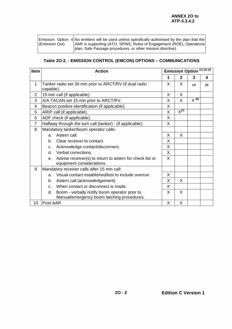
ANNEX 2O to ATP-3.3.4.2
2O - 2 Edition C Version 1
Emission Option 4 (Emission Out)
No emitters will be used unless specifically authorised by the plan that the AAR is supporting (ATO, SPINS, Rules of Engagement (ROE), Operations plan, Safe Passage procedures, or other mission directive).
Table 2O-2. - EMISSION CONTROL (EMCON) OPTIONS – COMMUNICATIONS
Item Action Emission Option (1) (2) (3)
1 2 3 4 1 Tanker radio set 30 min prior to ARCT/RV (if dual radio
capable). X X (4) (5)
2 15 min call (if applicable). X X 3 A/A TACAN set 15 min prior to ARCT/RV. X X X (6) 4 Beacon positive identification (if applicable). X 5 ARIP call (if applicable). X X(7) 6 ADF check (if applicable). X 7 Halfway through the turn call (tanker) - (if applicable). X 8 Mandatory tanker/boom operator calls: a. Astern call. X X b. Clear receiver to contact. X c. Acknowledge contact/disconnect. X d. Verbal corrections. X e. Advise receiver(s) to return to astern for check list or
equipment considerations. X
9 Mandatory receiver calls after 15 min call: a. Visual contact established/lost to include overrun. X b. Astern call (acknowledgement). X X c. When contact or disconnect is made. X d. Boom - verbally notify boom operator prior to
Manual/emergency boom latching procedures. X X
10 Post AAR X X

ANNEX 2O to ATP-3.3.4.2
2O - 3 Edition C Version 1
NOTES: 1. When using EMCON Options 2 - 4, boom interphone should be used when
receiver compatible. Tanker and receiver planners will co-ordinate and crews are to be thoroughly briefed on: RV type, RV point and time, tanker and receiver FL/altitudes/heights, cell procedures and break up arrangements, and missed RV procedures (including refuelling area departure time and back up communication procedures). If different EMCON options are to be used during different phases of the route, this must be included in the briefing.
2. Variations may be co-ordinated, e.g.: ‘EMCON 2, ITEM 9a COMMS N/A’ would mean normal EMCON Option 2 procedures except the astern call would be deleted.
3. EMCON Options 1 and 2 only are used when the FAF C135-FR is conducting pod refuelling.
4. Radio silent procedures. Use of other emitters is authorized unless prohibited by supported operations plans.
5. No emissions (radios, doppler, navigation transmissions, radar, IFF, exterior lighting, etc.) unless authorized by the ATO, Rules of Engagement (ROE), operations plans, safe passage procedures or other mission directives.
6. RV Bravo, Charlie, Delta (Point Parallel) and Echo. 7. Modified RV Delta (Point Parallel) procedure.
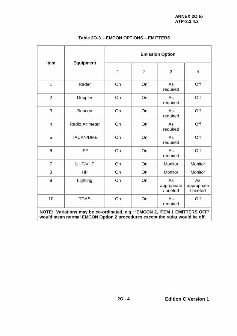
ANNEX 2O to ATP-3.3.4.2
2O - 4 Edition C Version 1
Table 2O-3. - EMCON OPTIONS – EMITTERS
Item Equipment
Emission Option
1 2 3 4
1 Radar On On As required
Off
2 Doppler On On As required
Off
3 Beacon On On As required
Off
4 Radio Altimeter On On As required
Off
5 TACAN/DME On On As required
Off
6 IFF On On As required
Off
7 UHF/VHF On On Monitor Monitor
8 HF On On Monitor Monitor
9 Lighting On On As appropriate
/ briefed
As appropriate
/ briefed
10 TCAS On On As required
Off
NOTE: Variations may be co-ordinated, e.g.: ‘EMCON 2, ITEM 1 EMITTERS OFF’ would mean normal EMCON Option 2 procedures except the radar would be off.

ANNEX 2P to ATP-3.3.4.2
2P - 1 Edition C Version 1
CHAPTER 2 FIXED WING PROCEDURES ANNEX 2P COMMUNICATION PROCEDURES
Serial (a)
Situation (b)
Tanker RT (c)
Receiver RT (d)
1 15 min prior to RV a. Set Radar/Rendezvous Beacon (where fitted) b. Set Air to Air TACAN to appropriate channel (ensure Y- or X- channel set appropriate to receiver capability)
a. Set Radar/Rendezvous Beacon (where fitted) b. Set Air to Air TACAN to appropriate channel (unless required for navigation) c. Transmit receiver IFF
2 RV Initial Call – made following ATC clearance to call (may be as much as 15 min prior to ARCT)
“(Receiver Callsign), (tanker callsign) for RV (type). My FL/altitude/height, when cleared, your FL/altitude/height, set A/A TACAN (channel), Mode 3, (timing if required), (and altimeter setting if not 1013.2mb (29.92 inches Hg))” (1)
“(Tanker Callsign), (receiver callsign), when cleared, my FL/altitude/height, TACAN (channel), Mode 3, (timing, if required), (and altimeter setting if not 1013.2mb (29.92 inches Hg)), (if appropriate, nose cold, switches safe)” (1)
3 Receiver has radar contact and takes responsibility for closing to visual range
- “(Callsign) Judy”
4 Receiver has visual contact approaching tanker
- “(Callsign) Visual”
5 Receiver cleared to join tanker
“(Callsign) Clear join” Acknowledge (2) (3)
6 Receiver in the Echelon Left Position
- “(Callsign) Echelon Left” (4)
7 Tanker AAR equipment deployed (hose trailed, boom lowered)
“(Callsign) Clear astern left/centre/right” (4)
Acknowledge (4) (5) (6)
8 Receiver astern left/centre/right
- “(Callsign) Astern left/centre/right (4) (6)
9 Tanker AAR equipment ready to pass fuel
“(Callsign) Clear contact (specify left/ right if a multi-point tanker)” (4) (7)
Acknowledge (8)
10 Closing to boom contact “Stabilize, Forward, Back, Up, Down, Right, Left, Return to astern” (4)
Acknowledge (4)
11 Receiver to disconnect “(Callsign) Disconnect” (4) Acknowledge (4) (9) 12 Receiver astern
left/centre/right - “(Callsign) Astern
left/centre/right”
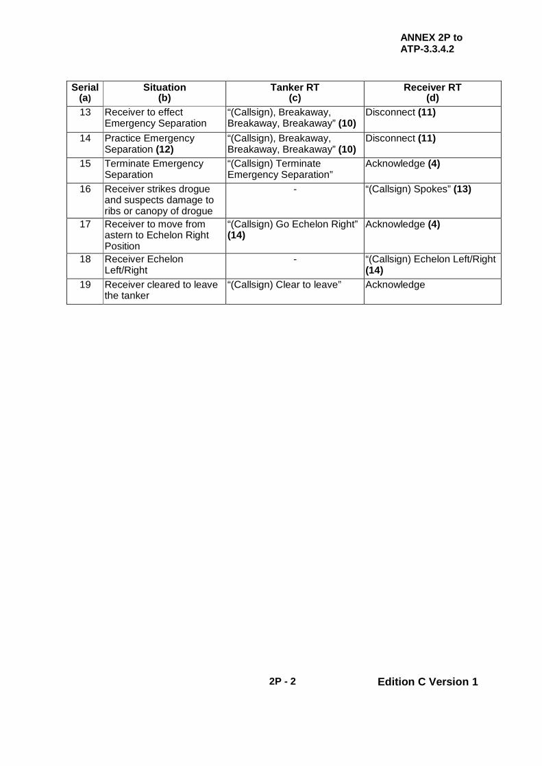
ANNEX 2P to ATP-3.3.4.2
2P - 2 Edition C Version 1
Serial (a)
Situation (b)
Tanker RT (c)
Receiver RT (d)
13 Receiver to effect Emergency Separation
“(Callsign), Breakaway, Breakaway, Breakaway” (10)
Disconnect (11)
14 Practice Emergency Separation (12)
“(Callsign), Breakaway, Breakaway, Breakaway” (10)
Disconnect (11)
15 Terminate Emergency Separation
“(Callsign) Terminate Emergency Separation”
Acknowledge (4)
16 Receiver strikes drogue and suspects damage to ribs or canopy of drogue
- “(Callsign) Spokes” (13)
17 Receiver to move from astern to Echelon Right Position
“(Callsign) Go Echelon Right” (14)
Acknowledge (4)
18 Receiver Echelon Left/Right
- “(Callsign) Echelon Left/Right (14)
19 Receiver cleared to leave the tanker
“(Callsign) Clear to leave” Acknowledge

ANNEX 2P to ATP-3.3.4.2
2P - 3 Edition C Version 1
Communication Procedures NOTES:
1. In some national airspace, ATC controllers permit receiver(s) to contact the tanker to discuss the RV whilst the receiver(s) is(are) still under ATC control. The tanker’s “when cleared” statement warns the receiver(s) that the RV information is not to be acted upon until ATC either releases the receiver(s) (e.g. MARSA) or approves changes in the receiver(s) flight parameters such as FL/altitude/height.
2. For Probe and Drogue/BDA operations, receivers form in the Echelon Left
position. 3. For boom operations, the first receiver may join directly to astern position, all
others form in the Echelon Left position. 4. Only required during EMCON Option 1. 5. Receiver moves behind the assigned AAR equipment and stabilizes in the astern
position. 6. Boom operations need not designate centre. 7. During EMCON Option 2, the boom operator and lead receiver will accomplish an
abbreviated radio check prior to boom contact, e.g. tanker: ‘36 Alpha, 42’, receiver: ‘36 Alpha’. If more than one receiver formation is on the AAR frequency, tanker will use the full receiver callsign. After contact, use the boom interphone to maximum extent possible.
8. Receiver advances to engage probe with drogue or moves to the boom contact
position. 9. Receiver makes a routine disconnect and drops back to the astern position. 10. To avoid confusion with multiple tankers on the same frequency, the specific
tanker callsign must preface the breakaway call. 11. See Chapter 2, para. 2.32. 12. Prior to a practice breakaway, in-flight co-ordination between the tanker crew and
receiver pilot is mandatory. 13. After a spokes, tanker and receiver consult to assess damage to AAR equipment
and establish feasibility of continuing AAR. 14. Tanker passes to receiver the amount of fuel transferred (Note: When known, use
the unit of measurement of the receiver’s fuel system, otherwise use the tanker’s unit of fuel measurement.)

ANNEX 2P to ATP-3.3.4.2
2P - 4 Edition C Version 1
INTENTIONALLY BLANK

ANNEX 2Q to ATP-3.3.4.2
2Q - 1 Edition C Version 1
CHAPTER 2 FIXED WING PROCEDURES ANNEX 2Q RADIO SILENT PROCEDURES
Table 2Q-1. - RADIO SILENT PROCEDURES - PROBE AND DROGUE
Serial (a)
Situation (b)
Tanker Actions (c)
Receiver Actions (d)
1 Receiver requires fuel - Receiver joins on tanker’s left side in the Echelon Left position, and extends probe (See notes 1 and 2)
2 Tanker acknowledges receiver presence, has understood and has fuel available
Trails hose -
3 Tanker acknowledges but has no fuel available
Tanker’s hose remains stowed or retracted
Receiver diverts or attempts to find another tanker (See note 4)
4 Tanker AAR equipment ready, receiver clear astern
Switch off all red anti-collision beacons/strobes. All on again when receiver seen to move behind the tanker
Receiver goes to the astern position behind the AAR equipment (right hose as first choice on multi-point tankers, if available)
5 Fuel transfer Light sequence as in National Annex (See note 4)
Receiver reacts to lights/visual signals
6 Receiver leaves formation
-
Receiver pulls forward on right side in visual contact then turns away
7 Receiver to breakaway a. Tanker AAR equipment red signal light on or flash. b. Some tankers will turn strobes lights on and navigation lights to bright. c. For tankers not fitted with AAR equipment red signal lights
(1) Any other specified red light on (e.g. anti-collision, hand held lamp).
(2) Refer to Tanker National SRDs for other variations.
Receiver makes emergency disconnect, moves back and then goes to a safe position clear of the tanker and the refuelling equipment, usually to echelon
NOTES: 1. For tankers where the crew is only on the flight deck (see appropriate Tanker National
SRD), receivers should pull well forward to attract the pilot’s attention. 2. For tankers with observers stationed in the rear of the aircraft (see appropriate Tanker
National Annex), receivers should not move forward of the tanker’s wing leading edge. 3. Receivers should depart the tanker using the prescribed procedures for refuelling (e.g. –
from the right side of the tanker, level or climbing). 4. It is not yet possible to propose standardized signals to indicate clearance for receivers
to commence and disconnect refuelling because AAR light signalling equipment is not fitted on NATO aircraft to a common STANAG.

ANNEX 2Q to ATP-3.3.4.2
2Q - 2 Edition C Version 1
Table 2Q-2. - RADIO SILENT PROCEDURES – ALDIS-EQUIPPED PROBE AND DROGUE
Serial
(a) Situation
(b) Tanker Actions
(c) Receiver Actions
(d) 1 Receiver requires fuel - Receiver joins on tanker’s left
side in the Echelon Left position (See notes 1 and 2)
2 Tanker acknowledges receiver presence, has understood and has fuel available
Trails hose Proceed to astern position on respective hose(s). (Right hose as first choice on multi-point tankers, if available)
3 Tanker acknowledges but has no fuel available
Tanker’s hose remains stowed or retracted
Receiver diverts or attempts to find another tanker (See note 3)
4 Receiver is cleared to contact hose.
One steady Aldis signal from respective side of aircraft.
Receiver engages drogue
5 Fuel transfer Light sequence as in National Annex (See note 5).
Receiver reacts to lights/visual signals
6 Receiver has briefed amount of fuel, or tanker has no additional give remaining.
One steady Aldis signal to receiver engaged in drogue.
Receiver disconnects and proceeds to Echelon Right.
7 Receiver has briefed amount of fuel, but request additional offload.
Tanker provides additional fuel in briefed increments, unless there is no additional offload (refer to item 6)
Receiver remains engaged in drogue after receiving steady Aldis signal.
8 Receiver is not satisfied with hose response or fuel flow rate.
Tanker resets hose response once receiver is clear of the hose.
Receiver disconnects, moves aft and outboard of hose, and awaits further signal from tanker.
9 Hose is unsafe Tanker retracts hose Receiver proceeds to open hose or departs tanker/tanker cell.
10 Tanker has a malfunction that requires receiver to momentarily disconnect
Flashing Aldis signal from the observer
Receiver disconnects, moves aft and outboard of hose, and awaits further signal from tanker.
11 Emergency requiring a breakaway exists
Tanker turns on lower anti-collision light
Receiver expeditiously disconnects from hose, moves aft and outboard, and awaits further signal from tanker. (See note 4)
NOTES: 1. For tankers where the crew is only on the flight deck (see appropriate Tanker National
SRD), receivers should pull well forward to attract the pilot’s attention. 2. For tankers with observers stationed in the rear of the aircraft (see appropriate Tanker
National SRD), receivers should not move forward of the tanker’s wing leading edge. 3. Receivers should depart the tanker using the prescribed procedures for refuelling (e.g. –
from the right side of the tanker, level or climbing). 4. When a breakaway is signalled for an emergency situation, receivers should avoid
exacerbating the situation with an excessively rapid disconnect from the hose. 5. It is not yet possible to propose standardized signals to indicate clearance for receivers to
commence and disconnect refuelling because AAR light signalling equipment is not fitted on NATO aircraft to a common STANAG.

ANNEX 2Q to ATP-3.3.4.2
2Q - 3 Edition C Version 1
Table 2Q-3. - RADIO SILENT PROCEDURES – BOOM
Serial
(a)
Boom/Receiver AAR Signal (b)
BDA/Receiver AAR Signal
(c)
Meaning
(d)
1 Receiver may join directly to astern position
Receiver requires fuel/training
2 Boom extended in trail.
Tanker ready for contact (See Note 1)
3
Boom in trail (fully extended) Tanker manual operation without disconnect capability
or Tanker acknowledgement of receiver’s manual boom latching signal
Boom in trail (fully extended)
Tanker ready for contact
4 Boom in trail (fully retracted) Boom in trail (fully retracted) Fuel offload complete
5
Same receiver returns to astern with receptacle door open (DAY): Pilot signals closed fist, thumb to mouth plus hand signalling number equating to one finger for every 1000lb of fuel required. (NIGHT): Same receiver returns to astern with receptacle door open, ready for contact. (See note 2)
Additional fuel required – EMCON 2-4
6 Boom stowed (fully retracted) Boom stowed (fully retracted)
Tanker AAR system inoperative
7 Boom 0° elevation, extended 5 ft
System malfunction. Tanker and receiver check AAR systems
8
Flashing pilot director lights (push emergency breakaway switch). Tanker lower rotating beacon on (Beacon light master switch to Both)
Flashing pilot director lights (push emergency breakaway switch). Tanker lower rotating beacon on (Beacon light master switch to Both)
Breakaway
9
Turn pilot’s director lights off during contact. Push disconnect signal switch (See note 3)
Turn pilot’s director lights off during contact. Push disconnect signal switch (See note 3)
Tanker request for disconnect, receiver return to astern position
10
Receiver closing and opening receptacle door when in astern position
Receiver request manual boom latching or
Receiver acknowledgement of tanker’s manual operation signal without tanker’s disconnect capability signal
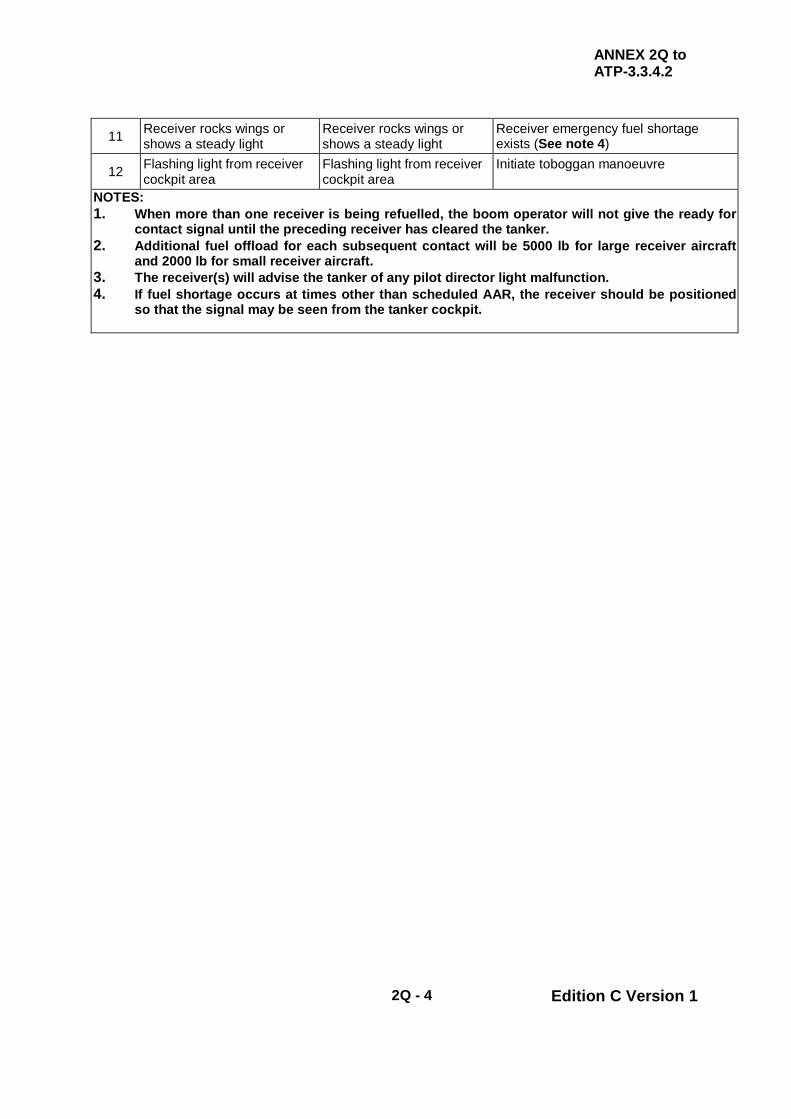
ANNEX 2Q to ATP-3.3.4.2
2Q - 4 Edition C Version 1
11 Receiver rocks wings or shows a steady light
Receiver rocks wings or shows a steady light
Receiver emergency fuel shortage exists (See note 4)
12 Flashing light from receiver cockpit area
Flashing light from receiver cockpit area
Initiate toboggan manoeuvre
NOTES: 1. When more than one receiver is being refuelled, the boom operator will not give the ready for
contact signal until the preceding receiver has cleared the tanker. 2. Additional fuel offload for each subsequent contact will be 5000 lb for large receiver aircraft
and 2000 lb for small receiver aircraft. 3. The receiver(s) will advise the tanker of any pilot director light malfunction. 4. If fuel shortage occurs at times other than scheduled AAR, the receiver should be positioned
so that the signal may be seen from the tanker cockpit.

ATP-3.3.4.2
3 - 1 Edition C Version 1
CHAPTER 3 ROTARY PROCEDURES SECTION I - PLANNING AND BRIEFING CONSIDERATIONS - HAAR
3.1. INTRODUCTION HAAR operations require precise and detailed planning to ensure success and crewmembers must be thoroughly familiar with all of the planning factors used to determine how the mission is to be executed. Consideration must be given to each factor resulting from various receiver/tanker capabilities and limitations. The procedures selected and resultant performance may not be the most efficient for either tanker or receiver aircraft; however, they must be within the operating limitations of each platform. 3.2. PLANNING CONSIDERATIONS
a. Fuel Transfer Rates. The transfer rates are normally 500-1,000 lbs per min; however, they are dependent on the tanker configuration. Specific National Annex should be consulted to determine the actual fuel transfer rate.
b. Hose Checks. If hose checks are required prior to conducting HAAR,
tanker crews should consider completing them prior to the RV to avoid unnecessary delays. This may require tankers to plan a period of reduced airspeed en route or an en route holding area.
c. HAAR Airspeed. To determine the indicated airspeed to be used for
HAAR, the performance capability of the helicopter must be determined and then compared with the tanker airspeed capability. All other factors being compatible, normal HAAR airspeed will be 110-115 KIAS. Refer to applicable national annexes for Minimum Operating Speed (MOS) definition and associated warnings. All airspeeds are indicated airspeeds (KCAS for MC-130H).
ATP-3.3.4.2
3 - 2 Edition C Version 1
d. HAAR Altitudes. The refuelling altitude should always be chosen with terrain and tactical considerations in mind. Minimum HAAR altitude will be in accordance with service or national directives. Maximum HAAR altitudes will be based on tanker and receiver performance.
e. HAAR Track. Whenever possible, allow sufficient HAAR track length to
complete fuel transfer without track reversals. Establish an ARIP a minimum of 6 nm prior to the ARCP. This point is part of the HAAR track and aids the tanker in identifying the receiver and determining their heading. Helicopters will plan to fly from the ARIP to the ARCP and then proceed along the air refuelling track. Consider the following when determining HAAR track length: the ARCP is normally the earliest point the tanker can pass abeam the receiver (not when fuel is flowing), amount of fuel to transfer, fuel transfer rate, number of tankers and receivers, hose time per receiver, ground speed, terrain, and routes of ingress and emergency egress. Never assume dual hose (simultaneous) operations. Plan to extend track length appropriately for winds, higher true airspeeds, unstable platforms, multiple receivers, hose problems, or unplanned additional fuel transfer factors. Optimize extended track orientation to match receiver’s capabilities and ingress and egress routing. If track length is not sufficient to accomplish HAAR without track reversal due to terrain, threat, or mission parameters, careful attention must be given to turn radius and power considerations for the turns.
WARNING
AIRSPEEDS OF LESS THAN 105 KIAS MAY CAUSE THE PARADROGUE TO BECOME SLIGHTLY LESS STABLE, AIRCREWS MUST BE VIGILANT OF A POTENTIAL LOSS OF HELICOPTER ROTOR TO TANKER TAIL CLEARANCE AND THE INCREASED POTENTIAL FOR MIDAIR COLLISION.
WHILE CONFIGURED FOR HAAR, THE TANKER HAS A SMALL MARGIN FOR SAFETY ABOVE POWER-OFF STALL SPEED. ABRUPT POWER REDUCTION AT HIGH GROSS WEIGHTS MAY RESULT IN A STALL WITH NO STALL WARNING.
HELICOPTERS WILL REFUEL FROM DROGUES CERTIFIED FOR HELICOPTER COMPATIBLE AIRSPEEDS. TANKERS SHOULD NOT EXTEND AN INCOMPATIBLE DROGUE DURING HAAR.

ATP-3.3.4.2
3 - 3 Edition C Version 1
f. Crewmember Briefing. Both tanker and receiver crews must be thoroughly familiar with the briefing items listed in Chapter 3, para. 3.2.g., Tanker/Receiver Briefing Card, to adequately plan for a mission. When possible, all items will be briefed prior to flight; otherwise, items will be briefed in flight prior to RV.
g. Tanker/Receiver Briefing Items. The following lists contain
planning/briefing considerations and are not necessarily all-inclusive. Crews should determine which items apply and amend as appropriate.
(1) Standard Briefing Items.
(a) Weather (Track, Destination, and Divert).
(i) Freezing level. (ii) Cloud tops.
(b) Tanker and receiver call signs. (c) Number of receivers/tankers. (d) Refuelling Formations.
(i) Option 1 / Option 2. (ii) Simultaneous AAR. (iii) Standby tanker requirements (in addition to Option
1 / 2 spare).
(e) Communications.
(i) AAR (Pri) / (Sec). (ii) Plain / Secure Voice. (iii) EMCON option. (iv) EMCON communications procedures. (v) Multi-colour light signals. (vi) Single-colour light signals.
(f) AAR Track (Published name, if applicable).
(i) Geo-reference (DATUM). (ii) Receiver ingress routing.

ATP-3.3.4.2
3 - 4 Edition C Version 1
(iii) AAR initial point (ARIP). (iv) AAR control point (ARCP).
(v) AAR control time (ARCT). (vi) AAR track/course. (vii) AAR airspeed. (viii) Formation or individual defensive tactics. (ix) Rejoin procedures. (x) AAR turn point(s). (xi) ENDAR. (xii) Abort point.
(xiii) Abort criteria. (xiv) Divert routing/destination. (xv) Emergency bases. (xvi) AAR exit point. (xvii) Air traffic control clearance limits. (xviii) Alternate track.
(g) AAR altitudes.
(i) RV altitude (tanker). (ii) Join up type and altitude (receiver high / low). (iii) AAR altitude. (iv) MSA (by leg if required). (v) Pre-planned Altimeter.
(h) RV type. (i) Tanker No Show procedures. (j) Receiver No Show procedures.

ATP-3.3.4.2
3 - 5 Edition C Version 1
(k) Special equipment (TACAN A/A, Beacon, IFF Setting /
Interrogator Transponder System / Low Probability Intercept [ITS/LPI]).
(l) Fuel.
(i) Time on station. (ii) Available. (iii) Receiver requirements.
(m) Receiver Disconnect Procedures. (n) Tanker/receiver lighting configuration and NVG
considerations. (o) Lost Contact procedures. (p) Emergency procedures. (q) Lost Communications. (r) Helicopter performance limitations.
3.3. TANKER / RECEIVER BRIEFING CARD To ensure all mission details are understood, a single mission briefing card should be developed for use by both tanker and receiver aircrews. The following briefing card, Figure 3-1, serves as an example of the type of information that should be contained on the card.

ATP-3.3.4.2
3 - 6 Edition C Version 1
HAAR BRIEFING TRACK INFORMATION
TRACK NAME: TRACK DATE: ARCT: / RV TYPE:
OPTION I/II: RCVR HI/LO: SPARE: JOINUP ALT: ’
SIMULTANEOUS: AR ALT: ’ LIGHTING: AIRSPEED:
ALT SET: FUEL SHUTOFF: LIGHT SIGNALS: MSA: ’
TANKER / RECEIVER INFORMATION ELEMENT 1 ELEMENT 2 SPARE
TANKER C/S: TANKER TCN:
RCVR C/S (1): Training Requested
RCVR C/S (2): Type of RV’: RCVR TACAN: Multiple Dry-plugs: RCVR MODE 1: Multi Cross-Overs:
RCVR MODE 2: EP Training: RCVR MODE 3A: Time on Track: 01+00
FUEL RQD EA: FUEL RQD TOT: RCVR TCN SEP:
COMMUNICATIONS / PRESETS ( * Denotes Secure) PRIMARY: - TERTIARY: -
SECONDARY: - COMMS TYPE: TRACK LOCATION INFORMATION
ID ACP HDG DIS (REM) LAT LONG ELEV IP nm N ° E ° ’ CP ° nm N ° E ° ’ TP1 ° nm N ° E ° ’ TP2 ° nm N ° E ° ’ TP3 ° nm N ° E ° ’ EP ° 00 nm N ° E ° ’
ABORT / DIVERT POINT INFO AP N ° E ° ’ DIV ° nm N ° E ° ’ REMARKS:
RCVR POC: TANKER POC:
Figure 3-1. - Tanker / Receiver Briefing Card Example

ATP-3.3.4.2
3 - 7 Edition C Version 1
CHAPTER 3 ROTARY PROCEDURES SECTION II - GENERAL PROCEDURES - HAAR
3.4. GENERAL HAAR may be divided into four stages of operation: RV (intercept/escort), join-up, contact/fuel transfer, and post air refuelling. 3.5. WEATHER REQUIREMENTS
a. Altimeter Settings. Prior to RV, every effort will be made to obtain the most accurate altimeter setting available to ensure safe terrain clearance. In the absence of an accurate ground station observation, a forecast minimum altimeter setting/QNH or aircraft system derived setting should be used unless the standard altimeter setting, 1013 mb (29.92 inches Hg), is required. Use of a forecast minimum altimeter setting will result in the greatest margin of safety. See Chapter 2, para. 2.2.a. for further details.
b. Visibility. Minimum visibility for a visual RV is 3 nm. Minimum visibility
for electronic RV is 1 nm. Equipment with the ability to determine receiver range is the minimum required for conducting electronic RV (e.g., Air to Air TACAN). Equipment that provides range and bearing (e.g., IFF interrogator or radar) meets this minimum equipment requirement.
c. Ceilings/Cloud Clearance. Minimum ceiling requirements should be
identified during the mission planning phase. National or service directives may dictate minimum weather requirements. It is recommended that the AAR altitude affords 1,000 ft of vertical clearance from the top or bottom of a broken/overcast (ceiling) during HAAR.
d. Cloud Avoidance. Flight through clouds after contact will be avoided.
WARNING
FLIGHT INTO CLOUDS OR OBSCURATION AFTER RV MAY RESULT IN SPATIAL DISORIENTATION AND POTENTIAL MIDAIR COLLISION.

ATP-3.3.4.2
3 - 8 Edition C Version 1
e. Weather Watch. It is paramount to the success of HAAR operations that a single coordinated forecast is provided to the agency having overall control (making go/no-go decisions). It is also imperative that a close weather watch be maintained throughout the operation to aid in making recalls, diversions, etc. should unexpected weather conditions critical to the operation occur.
3.6. RV PROCEDURES RV procedures provide the tanker a means of transitioning from escort/intercept conditions to a position 1/2 nm in trail of the receiver ready to begin the join-up. The tanker will normally accomplish all required manoeuvring during RV to preclude degradation of receiver capability; the exception to this is the RV Echo (tanker orbit RV). The type of RV selected is dependent on the situation and is determined during mission planning. Refer to Chapter 3, Section II, and Annexes 2A-H for the RVs specific to HAAR.
a. Communications. The receiver(s) and tanker(s) will monitor primary and alternate AAR frequencies and will have electronic RV equipment on a minimum of 10 min prior to ARCT. Communications will be per Chapter 3, Section v and the EMCON option in force.
(1) During initial radio contact (EMCON 1 and 2), tanker and receiver
aircrews will confirm the altimeter setting and identify any changes to the mission briefing.
(2) During EMCON 1 operations, after initial radio contact has been
established between the tanker and receiver, the tanker will assume radio control of the AAR evolution.
b. Arrival at ARCP. Both receivers and tankers should plan to arrive at the
ARCP on time; however, if a deviation is required, receivers should arrive at the ARCP early (no more than 1 min) and tankers should arrive at the ARCP late (no more than 1 min).
c. Receivers.
(1) Join-Up Altitude. Receivers should be established at or below
(above for receiver high) join-up altitude and at AAR airspeed no later than the ARIP, or at a previously briefed location. Receivers will be at join-up altitude no later than the ARCP. The join-up altitude is dependent on whether the join up is receiver high or receiver low.
(a) Receiver-Low Join. The join-up altitude is 300 ft below
refuelling altitude for receiver-low operations. Receivers should be established at or below join-up altitude and at AAR airspeed no later than the ARIP, or at a previously briefed location. Receivers will be at join-up altitude no later than the ARCP.

ATP-3.3.4.2
3 - 9 Edition C Version 1
(b) Receiver-High Join. The join-up altitude is 200 ft above
refuelling altitude for receiver-high operations. Receivers should be established at or above join-up altitude and at AAR airspeed no later than the ARIP, or at a previously briefed location. Receivers will be at join-up altitude no later than the ARCP.
(2) Hot Armament Procedures. To prevent inadvertent weapons
firing during refuelling operations, receivers will complete positive weapons check in accordance with appropriate aircraft checklists prior to the tanker coming abeam during join-up.
(3) RV Airspeed. Receivers should maintain 180 KCAS from IP to
CP or until the tanker passes abeam on course for all overtaking RVs (B, D, G and H if appropriate).
d. Tankers
(1) Prior to RV. During the initial stage of the RV, standard intercept
procedures will be employed to place the tanker on an intercept course with the receiver. The tanker will perform the astern checklist in sufficient time to allow an orderly accomplishment of the selected RV procedure.
(2) Ingress Options. The tanker will be established at RV altitude
no later than the ARIP or within 5 nm of the receiver. Two options exist for the tanker ingress altitude prior to the RV:
(a) Ingress at AAR Altitude.
(i) During RV manoeuvring (range information only),
if the tanker does not have visual contact with the receivers prior to passing within 1 nm, it will immediately establish a minimum of 500 ft vertical separation, or execute lost contact procedures.
(b) Ingress at RV altitude.
(i) Determining RV Altitude. An RV altitude ensures
vertical separation between tankers and receivers prior to positive visual contact. It is based on the AAR altitude and should be 500 ft above or below AAR altitude depending on the type of join-up. For a receiver-low join-up, RV altitude is above AAR altitude. For a receiver-high join-up, RV altitude is below AAR altitude.

ATP-3.3.4.2
3 - 10 Edition C Version 1
(ii) Prior to positive visual contact with the receivers, tankers should maintain the RV altitude. Once receivers are visually acquired, tankers may climb or descend to the refuelling altitude.
3.7. JOIN-UP PROCEDURES RV procedures position the tanker for join-up. The standard RV is conducted receiver low for a left-hose join-up. Join-up procedures from all types of RV are the same and enable the tanker to proceed from 1/2 nm in trail (at refuelling altitude) to the lead position and establish refuelling configuration. The tanker must maintain a positive rate of closure to avoid delaying refuelling operations; however, caution must be exercised to avoid a receiver tail chase situation.
a. Change of Formation Lead. At close range (1/2 nm), the tanker may (in accordance with EMCON option) advise the receiver(s): “ONE-HALF NM IN TRAIL” and reduce airspeed to affect the join-up. The tanker will initiate the contact checklist (if applicable) at the discretion of the pilot. As the nose of the tanker passes the receiver’s three o’clock position, the receiver will be in the abeam position. The receiver will then report: “VISUAL” in order to pass the lead. Normally, hoses are extended once the tanker has assumed the lead. Once the tanker has accepted the lead, the receivers may manoeuvre to the Echelon Left position.
b. Formation Lead Responsibilities. Once the tankers assume formation
lead, they are responsible for all navigation, weather avoidance, and position reporting.
3.8. CROSSOVER If a crossover is required, the receiver pilot will move to the outside of the tanker wingtip, 100 ft aft of the horizontal stabilizer, and increase altitude to a minimum of 50 ft above the tanker’s vertical stabilizer. A crossover will then be made by altering the receiver’s heading. During crossover, the receiver aircraft should be flown to a position outboard of the opposite wingtip aft of the horizontal stabilizer before descending into the opposite echelon position. This procedure eliminates the possibility of the receiver passing through the area of turbulence directly behind the tanker. 3.9. CONTACT/FUEL TRANSFER This section contains information to be used from the receiver’s arrival in the Echelon Left position until the completion of HAAR. The left side refuelling position will be primary; however, either side may be used.

ATP-3.3.4.2
3 - 11 Edition C Version 1
a. Clear Astern. After completion of the contact checklist and when the tanker is ready, the receiver will be cleared to the astern position on the appropriate hose. A single clearance from the Echelon Left position to the contact position may be used if briefed, or is standard procedure in accordance with the tanker’s National Annex; however, all receivers will stabilize in the astern position prior to attempting contact.
b. Clear for Contact. When the tanker is ready for contact, the receiver will
be cleared for contact on the appropriate drogue. The receiver will acknowledge this clearance (EMCON 1) and check that the tanker ready light is illuminated.
WARNING
BEFORE INITIATING A TURN AT NIGHT, THE TANKER PILOT MUST CONFIRM THE RECEIVER IS ESTABLISHED IN EITHER THE OBSERVATION OR THE REFUELLING POSITION. UNLESS AN EMERGENCY FUEL CONDITION EXISTS, RECEIVER CREWS WILL NOT ATTEMPT PROBE-TO-DROGUE CONTACT IN A TURN AT NIGHT. THE POSSIBILITY OF SPATIAL DISORIENTATION EXISTS WHEN THE PILOT MUST DIVIDE HIS ATTENTION BETWEEN THE DROGUE AND COORDINATING A TURN WITH REDUCED VISUAL REFERENCES AVAILABLE AT NIGHT. ONCE IN CONTACT, TURNS ARE PERMITTED, AS THE PILOT’S REFERENCE IS SOLIDLY ON THE TANKER.

ATP-3.3.4.2
3 - 12 Edition C Version 1
WARNING
UNDER NO CIRCUMSTANCE SHOULD THE PILOT STARE AT THE DROGUE, AS THIS WILL RESULT IN POOR AIRCRAFT CONTROL AND MAY RESULT IN SPATIAL DISORIENTATION. CONTACTING A HOSE WITH NO HYDRAULIC PRESSURE IS AN EMERGENCY PROCEDURE ONLY. DURING ALL AAR WET TRANSFERS, IF THE SEARCH RADAR IS NOT REQUIRED FOR NAVIGATION OR WEATHER AVOIDANCE, PLACE THE RADAR FUNCTION SWITCH TO SECTOR/STANDBY AND DIRECT THE RADAR ENERGY AHEAD OF THE AIRCRAFT (EXCEPTION: AN/APN-241 RADAR). WING/PROP TURBULENCE CAN CAUSE UNCONTROLLED SETTLING. IF SETTLING OCCURS WHILE CONNECTED TO THE DROGUE, DISCONNECT IMMEDIATELY. FAILURE TO DISCONNECT MAY RESULT IN DAMAGE TO THE PROBE AND POSSIBLE ROTOR BLADE-TO-PROBE CONTACT.
CAUTION
EXCESSIVELY HARD CONTACT BETWEEN THE PROBE AND DROGUE CAN DAMAGE THE REFUELLING NOZZLE. SHOULD THE DROGUE BECOME UNSTABLE FROM PROBE CONTACT CAUSING SECTIONS OF THE CLOTH MATERIAL TO FAIL, IT IS POSSIBLE FOR THE DROGUE TO COLLAPSE AND FOR THE HOSE TO RETRACT FULLY INTO THE POD. CONTACT WITH A MALFUNCTIONING DROGUE THAT IS ROTATING AT GREATER THAN ONE REVOLUTION PER SECOND MAY DAMAGE THE PROBE NOZZLE LOCK RING; A CLOCKWISE ROTATING DROGUE COULD RESULT IN PARTIAL OR COMPLETE UNTHREADING OF THE PROBE NOZZLE. THEREFORE, CONTACTS WITH THIS TYPE OF DROGUE MALFUNCTION SHOULD BE RESTRICTED TO OPERATIONAL NECESSITY.

ATP-3.3.4.2
3 - 13 Edition C Version 1
c. When hose slack and whip occur and are observed by the tanker scanner or reported by the receiver pilot, the receiver will be instructed to return to the Echelon Left position.
d. When the receiver is clear and the tanker response set switch is actuated, the hose in question will be observed to travel to full trail and the tanker ready light will illuminate. When cleared, the receiver may re-engage. If hose response is incorrect, the receiver will be directed to a spare hose, if available.
3.10. RECEIVER DISCONNECT To effect a normal disconnect, the receiver pilot will reduce power and airspeed while maintaining the normal disconnect position (approximately 5 to 10 ft above the contact position). This will cause the receiver to move slowly back from the tanker and the refuelling hose to extend. A normal disconnect will occur when the refuelling hose reaches its maximum extension.
WARNING
THE RECEIVER PILOT WILL NOT DESCEND BELOW DISCONNECT POSITION DURING THIS MANOEUVRE TO ENSURE MAXIMUM ROTOR BLADE-TO-DROGUE SEPARATION DURING AND AFTER DISCONNECT.
CAUTION
THE RESPONSE RESET SWITCH MUST NEVER BE ACTUATED WITH THE RECEIVER ENGAGED, AS THIS COULD CAUSE LOSS OF ALL RESPONSE CAPABILITY.
CAUTION
AN EXCESSIVE RATE OF DISCONNECT WILL ONLY AGGRAVATE ANY HOSE SINE WAVE MOTION.

ATP-3.3.4.2
3 - 14 Edition C Version 1
a. Hose Unlock at Full Extension. Since fuel pressure is off at full hose extension, the locking action is released. More force is required to disengage than was required to engage because the locking rollers of the reception coupling must now travel up the steeply inclined rear surface of the probe head.
b. Tanker Actions after Disconnect. After disconnect, the tanker will
maintain level flight and refuelling airspeed until the receiver(s) is confirmed clear.
3.11. AAR WITH ONE TANKER / TWO OR MORE RECEIVERS In the event more than one receiver is to be refuelled by a tanker (single-hose or simultaneous), the join-up will be performed as described in para. 3.7, with all receivers in left echelon formation. Refer to Figure 3-1.
a. Single Hose Procedures. When number one receiver moves into the refuelling position, the next receiver will maintain its extended Echelon Left position behind and to the left/right of the tanker, leaving room for the refuelling receiver to return to the Echelon Left position if directed by the tanker. Upon completion of refuelling, the first receiver will make a normal disconnect, per para. 3.10., move aft and clear of the tanker, and rejoin the helicopter formation in the last (most rearward) position. This procedure will be repeated until all receivers have been refuelled. Using this procedure, the first receiver to be refuelled will again be in the lead position when all receivers have completed refuelling.
b. Simultaneous Refuelling Procedures. When cleared by the tanker,
receivers designated to refuel on the tanker’s right side will cross over to the Echelon Right position.
(1) If the tanker is ready to begin refuelling, the receivers on the left
side may be cleared for contacts prior to the second element crossing over to the Echelon Right position.
(2) Receiver observers (scanners) will inform their crew of the other
receiver’s position prior to manoeuvring to the astern position and prior to moving from the refuelling position to disconnect.
CAUTION
OFF-CENTRE DISCONNECTS CAN DAMAGE THE REFUELLING NOZZLE.
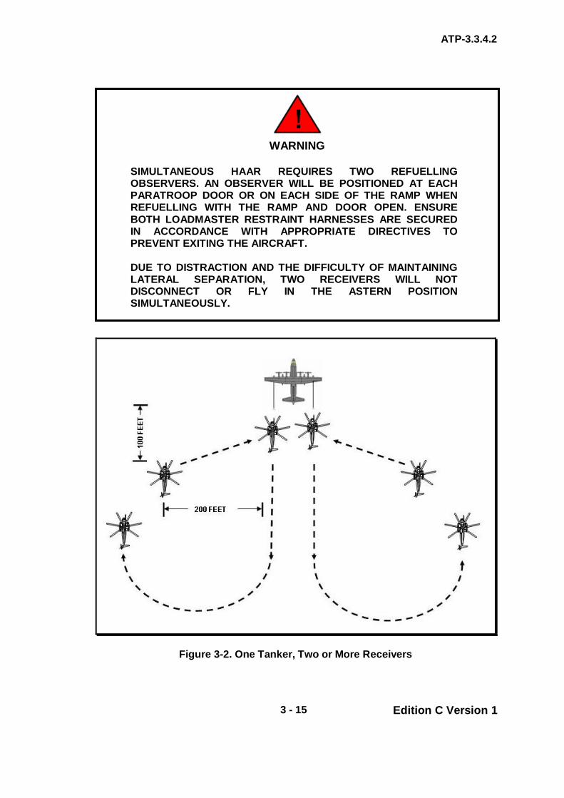
ATP-3.3.4.2
3 - 15 Edition C Version 1
Figure 3-2. One Tanker, Two or More Receivers
WARNING
SIMULTANEOUS HAAR REQUIRES TWO REFUELLING OBSERVERS. AN OBSERVER WILL BE POSITIONED AT EACH PARATROOP DOOR OR ON EACH SIDE OF THE RAMP WHEN REFUELLING WITH THE RAMP AND DOOR OPEN. ENSURE BOTH LOADMASTER RESTRAINT HARNESSES ARE SECURED IN ACCORDANCE WITH APPROPRIATE DIRECTIVES TO PREVENT EXITING THE AIRCRAFT. DUE TO DISTRACTION AND THE DIFFICULTY OF MAINTAINING LATERAL SEPARATION, TWO RECEIVERS WILL NOT DISCONNECT OR FLY IN THE ASTERN POSITION SIMULTANEOUSLY.

ATP-3.3.4.2
3 - 16 Edition C Version 1
NOTE
RECEIVERS DESIGNATED TO REFUEL ON THE RIGHT HOSE MAY CROSS OVER INDIVIDUALLY, IN SEQUENTIAL ORDER, OR SIMULTANEOUSLY AS A FORMATION ELEMENT. FORMATION CROSSOVERS REQUIRE CONSIDERABLE ADDITIONAL POWER FOR WINGMEN IN THE ELEMENT SINCE THEY MUST MOVE FROM LEFT ECHELON FORMATION TO THE RIGHT ECHELON PRIOR TO THE ELEMENT LEADER REACHING THE ECHELON RIGHT POSITION.
3.12. MULTIPLE DRY CONTACTS (TRAINING)
a. Request for Multiple Dry Contacts. If not previously briefed, receivers may request multiple dry contacts by stating: “REQUEST MULTIPLE DRY CONTACTS ON THE LEFT (OR RIGHT).” The tanker will approve multiple dry contacts by stating:
“CLEARED FOR MULTIPLE DRY CONTACTS ON THE LEFT (OR RIGHT).”
b. Cessation of Multiple Dry Contacts. This series of manoeuvres,
contacts, and disconnects may be continued at the discretion of the receiver pilot until the clearance for multiple dry contacts is cancelled or the receiver requests clearance to the Echelon Left position.
3.13. COMPLETION OF AAR
a. Disconnect. When fuel transfer is completed, the tanker will clear the receiver to disconnect unless otherwise briefed. The receiver will disconnect as described in para. 3.10.
b. Formation Element Rejoin. When both receiver elements have
completed AAR operations, the helicopter formation rejoin can be executed, prior to or after tanker departure, as briefed.
c. Formation Rejoin. After disconnect, receiver aircraft rejoin in the
Echelon Left or Right position in an Echelon Left or Right formation. After the flight is joined, the flight may descend to a tactical altitude, exercising caution not to drift under a tanker with extended hoses.
d. Formation Break-up. When the receiver(s) call(s) clear of the tanker,
the tanker will retract the hoses and accelerate away from the receiver flight. Both tanker and receiver(s) will ensure adequate separation prior to initiating any turns.
3.14. En route/Escort Procedures The information contained in this section will apply when two or more airplanes are involved in an en route formation with subsequent air refuelling. If more specific instructions are necessary, they should be included in an operations order.

ATP-3.3.4.2
3 - 17 Edition C Version 1
NOTE
DURING ESCORT OPERATIONS, INBOUND TANKERS WILL COORDINATE WITH THE ESCORTING TANKER ON A DISCRETE FREQUENCY.
a. Formation Escort. Under certain conditions (i.e. long flights over water, desolate terrain, weather avoidance), the receiver(s) may require escort. The situation will dictate the escort procedures; however, the following methods should be considered:
(1) Method 1. Low altitude escort position for the tanker will be
1,000 ft above (or below) and 1 to 2 nm in trail behind the receivers.
(2) Method 2. If tanker weight and/or receiver airspeed prohibit
maintaining a position 1 to 2 nm in trail of the receiver flight, the tanker will maintain vertical separation and fly a procedure turn, variable dogleg, or progressive racetrack escort.
(3) Method 3. If weather or other concerns warrant, the tanker may
fly as the formation lead.
NOTE
WEATHER RECONNAISSANCE MAY BE A TASK ASSIGNED TO THE ESCORTING TANKER. IN CERTAIN SITUATIONS, THE TANKER MAY BE REQUIRED TO DETACH FROM THE HELICOPTER(S) AND PROCEED DOWN COURSE TO BETTER FACILITATE THIS TASK. IN THIS EVENT, TANKERS WILL AFFECT A NORMAL RV UPON THEIR RETURN AND RESUME ESCORT DUTIES USING THE OPTIONS LISTED ABOVE.
a. Refuelling During Escort Mission. If refuelling is to be conducted
during the escort mission, the ARCT will be planned such that all receivers will be refuelled or in the process of refuelling prior to the abort point.
(1) Prior to initiating join-up from the escort position, the tanker will
complete all appropriate checklists and direct the receiver(s) to climb/descend to join-up altitude. The tanker will proceed to refuelling altitude after the receiver(s) report level.
(2) At the completion of fuel transfer, when the receiver(s) is clear,
the tanker will accelerate away from the receiver flight. Both tanker and receiver(s) will ensure adequate separation prior to initiating any turns.
ATP-3.3.4.2
3 - 18 Edition C Version 1
b. Replacement Tanker. If the requirement exists for a replacement tanker to RV with the AAR formation en route, it will do so at least 30 minutes prior to abort time, or as briefed. It will remain 1,000 ft above escort or refuelling altitude (whichever is higher) until all aircraft in the formation are in sight. Once in sight, the replacement tanker should position itself 1 to 2 nm behind the trail aircraft in the formation. When the primary tanker is complete with refuelling and has departed the formation, the replacement tanker will assume duties/position as the escort.
3.15. ON-CALL (UNPLANNED) HAAR Some tactical situations may require receivers to request HAAR with little or no planning. Examples include “Texaco,” anchor tracks, en route track procedures, and off-track manoeuvring. On-call HAAR may be accomplished on established anchor tracks, a series of pre-planned points/routes, an extension of an existing HAAR track, or unplanned points or tracks. Tanker crews must have a thorough understanding of receiver(s) mission requirements and routing before accepting an on-call HAAR.
a. Requesting On-Call HAAR. Receivers will use the brevity term “Texaco” to request an on-call HAAR. The receiver will relay to the tanker the ARCP coordinates/waypoint identifier/range and bearing from bull’s eye or other known/pre-briefed position, ARCT, track heading, requested fuel, and number of receivers. Tanker aircrews, after examining the terrain on the track, will compute and relay refuelling altitude, MSA, and time status to receivers.
b. Terrain Avoidance. Crews will have MSA and recommended refuelling
altitude prior to join-up on any on-call track. Tanker aircrews are responsible for maintaining terrain clearance on track and will recompute track heading and refuelling altitude as the terrain or threat dictate.
3.16. RV FROM A GROUND LAAGER In some instances, the receiver helicopter may be so low on fuel that they opt to land to conserve fuel. The following may be used as a guide when setting up tactical RV procedures from a ground laager. Receivers will confirm with the tankers the exact procedure to be used.
a. Land with sufficient fuel to allow for a shutdown, start and RV with the tanker.
b. Determine track heading and select an ARCP 2 nm from helicopter’s
ground laager location. c. Pass ARCP coordinates/waypoint, track heading and requested onload
to refuelling coordinator. d. The tanker will calculate the ARCT and pass to the receiver.

ATP-3.3.4.2
3 - 19 Edition C Version 1
e. The tanker will fly over the helicopter position on the prearranged track at refuelling altitude with hoses extended, ready for contact.
f. Tanker will give an advisory call at 2 min prior to arriving at ARCT. g. Receivers will depart to make the ARCT. Immediately climb to join up
altitude and accelerate to refuel airspeed. h. Conduct standard join-up and refuel procedures. i. If the receiver(s) cannot make the ARCT, the tanker may arrive
overhead the helicopter location, establish contact configuration, and continue to orbit the helicopter(s) while it is (they are) started and readied for takeoff. The receiver will takeoff to an arranged heading and altitude, the tanker will adjust as required and perform a RV.
3.17. NO-SHOWS
a. Receiver No-Shows. If the receivers are not acquired by the ARIP, the tankers will slow to 180 KIAS between ARIP and ARCP and proceed down track at the RV altitude. At ARCP adjust airspeed as required. The tanker should continue along the refuelling course long enough to ensure the receivers have not passed by unobserved, and then execute the briefed no-show plan.
b. Tanker No-Shows. If no contact, voice or visual, is established between
the receiver and the tanker by ARCP, the receiver shall continue along the refuelling track at the join-up altitude until reaching the abort point or, in the case of a static track, the turn point. Further actions will be mission dependent and should be briefed to both the tanker and receiver crews.
3.18. TYPES OF RV
a. RV Alpha (Anchor RV). Not used for HAAR. b. RV Bravo (Head-on). The tanker approaches the receiver(s) on the
reciprocal of the refuelling track and makes a procedure turn to roll out behind the receiver(s); details are at Chapter 3 Annex 3B.
c. RV Charlie. Not used for HAAR. d. RV Delta (Head-on offset). The head-on offset RV is the most
frequently used procedure and may be performed electronically (minimum visibility of 1 nm) or visually (minimum visibility of 3 nm); details are at Chapter 3 Annex 3D.
e. RV Echo (Tanker Orbit). This is the only RV in which the receiver
manoeuvres the aircraft to affect the RV and join-up; details are at Chapter 3 Annex 3E.
ATP-3.3.4.2
3 - 20 Edition C Version 1
f. RV Foxtrot (Sequenced). Not used for HAAR.
g. RV Golf (En route). The tanker approaches the receiver from the rear using visual (minimum visibility 3 nm) or electronic (minimum visibility 1 nm) means; details are at Chapter 3 Annex 3G.
h. RV Hotel (Random). The RV Hotel (Random RV) is used during VMC
as a method to facilitate an RV without losing visual contact with the receiver(s); details are published at Chapter 3 Annex 3H.
ANNEX 3A TO ATP-3.3.4.2
3A - 1 Edition C Version 1
CHAPTER 3 ROTARY PROCEDURES ANNEX 3A RV ALPHA
Not used for HAAR .

ANNEX 3B TO ATP-3.3.4.2
3B - 1 Edition C Version 1
CHAPTER 3 ROTARY PROCEDURES ANNEX 3B RV BRAVO
3.B.1. HEAD-ON RV See Figure 2D-1. The tanker approaches the receiver(s) on the reciprocal of the refuelling track and makes a procedure turn to roll out behind the receiver(s). This RV differs from the RV Delta in that the tanker does not offset from the receiver(s) course. Tankers will be established at RV altitude prior to initiating this RV and will not descend/climb to AAR altitude until visual with the receiver(s). There are two methods to affect this RV. 3.B.2. EQUIPMENT REQUIREMENT The tanker must have range equipment to employ Method 1. Relative bearing or visual acquisition of the receiver is sufficient for Method 2. 3.B.3. METHOD 1 PROCEDURES See Figure 3B-1. The tanker turn distance is computed using Table 3B-1 and the desired trail distance (completion of turn) is subtracted.
a. Determine Turn Point Range (TPR). A turn initiated at the range derived from Table 2B-1 would result in the tanker rolling out abeam the receiver once the following procedure was fully executed. This is the baseline TPR.
b. Determine Trail Distance. Prior to RV, determine required tanker trail
distance behind receiver formation. c. Modified Turn Distance. Compute the modified turn distance by
subtracting the desired trail distance from the calculated TPR. d. Turn Procedure.
(1) At the modified turn distance computed in para. 3.B.3.c, the
tanker turns 45°, using a 1/2 standard rate turn and maintains this heading for 1 min and 15 sec (2).
(2) At the completion of timing (3), the tanker turns 225°, using 1/2
standard rate, to the receiver’s heading (4). (3) At the completion of this turn, the tanker will be established at the
predetermined trail distance in a position to commence the join-up.

ANNEX 3B TO ATP-3.3.4.2
3B - 2 Edition C Version 1
e. Decreasing Turn Range/Radius. To decrease the turn range or radius, a standard rate turn may be used; however, the procedure must be modified as follows:
(1) Divide the tanker turn range (computed in Table 3B-1) by 2 then
subtract desired in-trail distance. (2) Hold the 45°outbound leg for 38 sec vice 1 min, 15 sec.
Figure 3B-1. Head-On RV (Method 1)

ANNEX 3B TO ATP-3.3.4.2
3B - 3 Edition C Version 1
Table 3B-1. - TURNING POINT RANGE (TPR) IN NM - ONE-HALF STANDARD RATE TURN (1-1/2° PER SEC) Tanker Helicopter TAS
TAS 80 90 100 110 120 130 140 150 160 10.4 11.1 11.8 12.5 13.2 13.9 14.6 15.3 170 10.7 11.4 12.1 12.8 13.5 14.2 14.9 15.6 180 11.0 11.7 12.4 13.1 13.8 14.5 15.2 15.9 190 11.3 12.0 12.7 13.4 14.1 14.8 15.5 16.2 200 11.6 12.3 13.0 13.7 14.4 15.1 15.8 16.5 210 11.9 12.6 13.3 14.0 14.7 15.4 16.1 16.8 220 12.2 12.9 13.6 14.3 15.0 15.7 16.4 17.1 230 12.5 13.2 13.9 14.6 15.3 16.0 16.7 17.4 240 12.8 13.5 14.2 14.9 15.6 16.3 17.0 17.7 250 13.1 13.8 14.5 15.2 15.9 16.6 17.3 18.0 260 13.4 14.1 14.8 15.5 16.2 16.9 17.6 18.3 270 13.7 14.4 15.1 15.8 16.5 17.2 17.9 18.6 280 14.0 14.7 15.4 16.1 16.8 17.5 18.2 18.9
3.B.4. - METHOD 2 PROCEDURES See Figure 3B-2. This method is a visual or bearing only manoeuvre.
a. The tanker reduces airspeed to 180 KIAS prior to passing abeam the receiver (1).
b. As the receiver passes the wing, the tanker executes a 210°standard
rate turn and descends/climbs to AAR altitude once in visual contact with the receiver (2).
c. At the completion of the turn (3), the tanker manoeuvres behind the
receiver and commences the join-up (4).

ANNEX 3B TO ATP-3.3.4.2
3B - 4 Edition C Version 1
Figure 3B-2. Head-On RV (Method 2)

ANNEX 3C to ATP-3.3.4.2
3C - 1 Edition C Version 1
CHAPTER 3 ROTARY PROCEDURES ANNEX 3C RV CHARLIE
Not used for HAAR.

ANNEX 3D to ATP-3.3.4.2
3D - 1 Edition C Version 1
CHAPTER 3 ROTARY PROCEDURES ANNEX 3D RV DELTA
3.D.1. HEAD-ON OFFSET RV See Figure 3D-1. The head-on offset RV is the most frequently used procedure and may be performed electronically (minimum visibility of 1 nm) or visually (minimum visibility of 3 nm). The tanker normally executes a left RV turn; however, if the situation dictates, right turns may be used. 3.D.2. The tanker approaches the receiver(s) on the reciprocal of the HAAR track at RV altitude with a 2 to 5 nm lateral offset. The optimum lateral offset is 3 nm. 3.D.3. As the tanker passes abeam the receiver(s), approximately 3 minutes prior to ARCT, commence 180° turn to initiate the RV. Minimum trail distance may be as little as 2 nm.
a. To expedite the RV, the turn may be initiated when the receiver is at the tanker’s 10 o’clock position. This is a visual manoeuvre only and will result in trail distance as little as 1/2 nm.
b. For formation Tanker Option 2 RVs (see Chapter 3, para. 3.21), in which
the tanker element passes abeam the trail receiver element, the tanker element should plan to arrive abeam the ARIP 4 min prior to the ARCT.
NOTE
(USAF AFSOC/ACC AND US ARMY ONLY) – IF THE TURN BACK TO TRACK IS BASED ON RECEIVER(S) POSITION, ENROUTE TIMING MAY END ABEAM THE ARIP.
3.D.4. If receivers are not acquired prior to passing abeam the ARIP, the tanker(s) shall reverse course and proceed along the AAR track at RV altitude and execute receiver no show procedures (para. 3.14.a.).

ANNEX 3D to ATP-3.3.4.2
3D - 2 Edition C Version 1
Figure 3D-1. Head-On Offset RV

ANNEX 3E to ATP-3.3.4.2
3E - 1 Edition C Version 1
CHAPTER 3 ROTARY PROCEDURES ANNEX 3E RV ECHO
3.E.1. - TANKER ORBIT RV (VMC ORBIT) See Figure 3E-1. This is the only RV in which the receiver manoeuvres the aircraft to affect the RV and join-up. 3.E.2. The tanker maintains the orbit at a specified location arriving over the ARCP at briefed intervals.
a. The standard orbit consists of 6 nm (3 min) legs with one 1/2 standard rate turn at the end of each leg. This results in one complete orbit every 10 min. Crews may adjust the size of the orbit according to mission requirements; however, tankers should strive to arrive over ARCP at the briefed interval, starting at ARCT. Orbits of non-standard duration should be described as RV-E 15, 20, etc., where the number identifies the time between tanker arrivals over ARCP.
b. An alternate tanker orbit consists of the tanker orbiting around a pre-
briefed, fixed point while maintain a constant bank turn (usually 20° angle of bank). This orbit allows the tanker to maintain refuelling airspeed and configuration to expedite refuelling operations. The receiver uses turn radius cut-off to affect the RV.
3.E.3. The receiver(s) will maintain 500 ft of vertical separation until the tanker is in sight. 3.E.4. Once the tanker is in sight, the receiver is cleared to join in the Echelon Left position. Once the receiver has commenced the join-up, the tanker should maintain a constant turn until join-up is complete. When the join-up is complete, the tanker will proceed as briefed.

ANNEX 3F to ATP-3.3.4.2
3F - 1 Edition C Version 1
CHAPTER 3 ROTARY PROCEDURES ANNEX 3F RV FOXTROT
Not used for HAAR.

ANNEX 3G to ATP-3.3.4.2
3G - 1 Edition C Version 1
CHAPTER 3 ROTARY PROCEDURES ANNEX 3G RV GOLF
3.G.1. EN ROUTE (OVERTAKING) RV See Figure 3G-1. The tanker approaches the receiver from the rear using visual (minimum visibility 3 nm) or electronic (minimum visibility 1 nm) means. The procedures outlined in para. 3.11 apply. 3.G.2. Tanker and receiver(s) may arrive over the ARIP from different directions; however, their course from ARIP to ARCP will be the same.
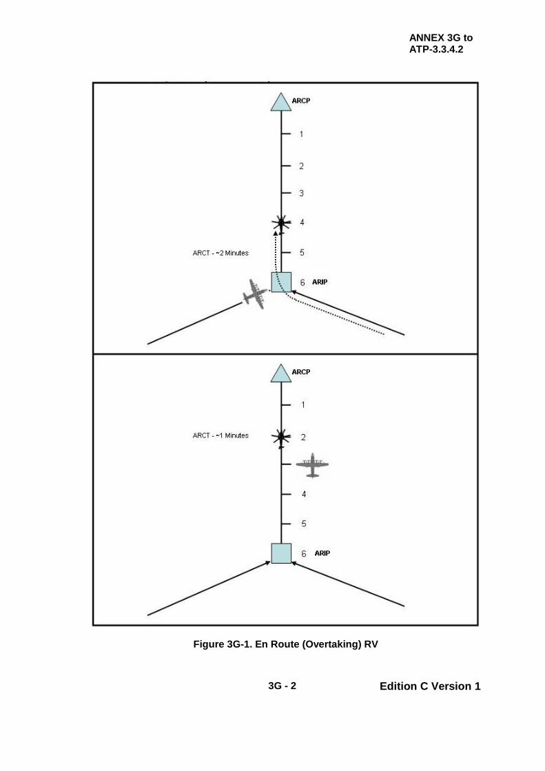
ANNEX 3G to ATP-3.3.4.2
3G - 2 Edition C Version 1
Figure 3G-1. En Route (Overtaking) RV

ANNEX 3H to ATP-3.3.4.2
3H - 1 Edition C Version 1
CHAPTER 3 ROTARY PROCEDURES ANNEX 3H RV HOTEL
3.H.1. RANDOM RV The RV Hotel (random RV) does not make use of a prescribed pattern or procedure. It will be used during VMC as a method to facilitate an RV without losing visual contact with the receiver(s). The tanker pilot should position his aircraft so as to maintain visual contact. This procedure is designed to expedite RV, to maintain visual contact once established and to allow the tanker pilot to manoeuvre the tanker as required to accomplish a successful RV. 3.H.2. Tankers will establish RV altitude at least 5 nm from receiver(s) and maintain this altitude until visual contact is established.
a. Confirm receiver(s) is at join-up altitude. b. With receiver(s) in sight, descend/climb to refuelling altitude (as
required) and manoeuvre to one-half nm in trail and proceed with join-up procedures.

ANNEX 3H to ATP-3.3.4.2
3H - 2 Edition C Version 1
INTENTIONALLY BLANK

ATP-3.3.4.2
3 - 20 Edition C Version 1
CHAPTER 3 ROTARY PROCEDURES SECTION III – FORMATION PROCEDURES - HAAR
3.19. HAAR FORMATION OPTIONS The refuelling formations described in this chapter are designed for HAAR missions requiring multiple tankers. Planners should consider using these procedures when refuelling multiple receivers. Both tanker and receiver aircrews must be well versed in these procedures for them to be effective. Any deviations from these procedures will be coordinated with all participants. The tanker RV typically starts with tankers in a trail formation. During the RV, tankers adjust their formation so as to arrive abeam the receivers as described in the following paragraphs. 3.20. HAAR FORMATION OPTION 1 HAAR Formation Option 1 (Figure 3-1) consists of two tankers: one primary and one spare. This formation is well suited for refuelling up to four receivers. When using this formation, receivers refuel from the primary tanker.
a. RV and Join-Up. Tanker aircraft will typically execute the RV using the trail formation.
b. Spare Tanker Positioning. Spare tanker maintains position as
described in para. 3.22. c. Transition to Spare Tanker. Transition to spare tanker position will be
accomplished as described in para. 3.23. d. Completion of Refuelling. After refuelling is complete, the primary
tanker will maintain refuelling airspeed until the spare is rejoined in a right echelon. The formation will then proceed as briefed.
3.21. FORMATION OPTION 2 (TRAIL) HAAR Formation Option 2 (Figure 3-2) consists of at least two primary tankers and one spare tanker, if available. This formation is well suited for refuelling more than four receivers.
a. Helicopter Element Spacing. Prior to reaching the ARIP, the helicopter flight separates into two elements in trail. Standard spacing between helicopter elements is 2 nm; however, it may be as little as 1/2 nm and should be determined based on mission requirements such as number of receivers, terrain, forecast visibility, and light conditions. Non-standard spacing should be specifically briefed. If using TACAN A/A to conduct the RV, all distance references should be made from the lead helicopter of the lead element. Using the lead helicopter as the reference simplifies the RV and alleviates the requirement for multiple TACAN Air-to-Air
ATP-3.3.4.2
3 - 21 Edition C Version 1
channels. The ARCT is the control time for arrival of the lead helicopter element at the ARCP.
b. Tanker Formation Positions. Tanker aircraft typically execute the RV
using the trail formation. When employing formations of two or three aircraft, the No. 1 and No. 2 primary tankers assume the lead and dash 2 positions. If there is a spare tanker, it assumes the dash 3 position. When employing formations of four aircraft (two primary and two spares), the first element consists of the No. 1 primary tanker and No. 1 spare; the second element consists of the No. 2 primary tanker and No. 2 spare. See Figure 3-3.
c. Join-Up. There are two methods that can be used to affect the join-up.
In either case, once the join-up is complete, the No. 2 tanker element should adjust its position (vertically / laterally) as required to account for turbulence from the lead element.
(1) Method 1. The tankers maintain formation until they approach
the second helicopter element (trailing element). At this point, the No. 2 primary tanker (and spare, if applicable) drops out of the formation and completes the join-up on the trail helicopter element. The lead primary tanker (and spare, if applicable) continues forward to join-up on the lead helicopter element.
(2) Method 2. Prior to the ARIP, the primary tankers establish
spacing between themselves that is equal to the briefed spacing between helicopter elements. If one spare is available, it remains with the No. 2 primary tanker. If two spares are available, they remain with their respective primary. From this point, they execute individual join-ups on their respective elements.
3.22. SPARE TANKER POSITIONING
a. Formation Position. Prior to join-up, the spare tanker(s) assumes an echelon position approximately 500 to 2,000 ft to the right of its respective primary tanker.
b. Vertical Position. The vertical position of the spare tanker, in reference
to the primary, is generally co-altitude. The decision to assume a stepped-up or stepped-down position (approximately 50 ft) is dependent on the refuelling altitude, visibility, and ease of maintaining proper position.
c. Transition to Spare Position. The transition to this spare position
should be done early enough to allow the primary tanker latitude in manoeuvring and airspeed changes during RV.
d. Configuration of Spare Tanker. The spare tanker(s) configures its
hoses at the same time as its respective primary tanker.
ATP-3.3.4.2
3 - 22 Edition C Version 1
e. Change of Configuration. When the primary tanker(s) signals “fuel flowing,” the spare(s) may retract its hoses or keep its hoses trailed during the entire refuelling evolution.
f. Tanker Activity during Evolutions. During evolutions employing three
tankers, tanker flight leaders may elect to have the spare tanker maintain its position on the No. 2 primary once “fuel flowing” is signalled or accelerate to join as the spare on the No. 1 primary. Regardless of the method selected, the spare tanker should be prepared to execute a timely transition should either primary tanker experience a malfunction.
3.23. TRANSITION TO SPARE TANKER If a primary tanker is unable to refuel, it will give the “go to spare tanker” signal and then accelerate, climb 500 ft, and, when clear, turn to rejoin the flight in the spare position at the end of the formation. The spare tanker will assume primary tanker duties by manoeuvring forward and allowing the receivers to move laterally (not aft) to the Echelon Left position. This manoeuvre may be difficult to execute should the No. 2 primary tanker experience a malfunction. Aircrews must recognize that the intent is for the primary tanker to safely give way for the spare to assume duties as the primary. Deviations may be required if element spacing is less than 2 nm. 3.24. COMPLETION OF REFUELLING Once refuelling is complete, the lead element will retract hoses and maintain refuelling airspeed until all tankers are joined in right echelon. During evolutions involving three tankers, final aircraft formation positions will depend on the spare tanker’s position at the completion of refuelling.

ATP-3.3.4.2
3 - 23 Edition C Version 1
Figure 3-3. Helicopter AAR Formation Option 1

ATP-3.3.4.2
3 - 24 Edition C Version 1
Figure 3-4. Helicopter AAR Formation Option 2 with Three Tankers
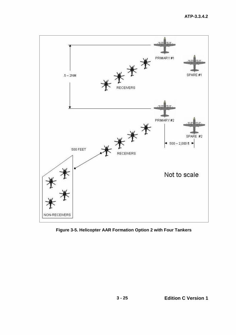
ATP-3.3.4.2
3 - 25 Edition C Version 1
Figure 3-5. Helicopter AAR Formation Option 2 with Four Tankers

ATP-3.3.4.2
3 - 26 Edition C Version 1
CHAPTER 3 ROTARY PROCEDURES SECTION IV – SAFETY PROCEDURES
3.25. INTRODUCTION The foundation for the safe conduct of HAAR by national or multi-national forces is standard, simple and unambiguous procedures. With these criteria established, multi-national HAAR is practicable by day and night, and during periods of EMCON constraint. 3.26. UNAIDED HAAR (NON-NVG)
a. RV. For RV, both the lead and trail receiver will carry a strobe.
b. Join-Up.
(1) Receivers. Receiver(s) will have lighting configured no later than ARIP.
(2) Tankers. During join-up, the tanker will set refuelling lights no
later than 1/2 nm in trail of the receiver(s). (3) Post Join-Up. After join-up, the trailing receiver will carry the
strobe for the formation. If conducting refuelling with a spare tanker, it will carry the strobe for the formation.
(4) Crossover. If a crossover is required, the receiver will ensure he
can determine the tanker’s vertical stabilizer height prior to commencing the crossover. If requested by the receiver, the tanker may turn on its strobe/anti-collision light to assist receivers in maintaining tanker vertical stabilizer clearance. The tanker will secure the strobe/anti-collision light once the crossover is complete.
WARNING
SOME TANKERS HAVE THE UPPER STROBE LOCATED ON THE TOP OF THE FUSELAGE AT THE WING ROOT. RECEIVERS MUST ENSURE ADEQUATE SPACING IS MAINTAINED FROM THE TANKER’S UNLIT VERTICAL STABILIZER DURING CROSSOVER.

ATP-3.3.4.2
3 - 27 Edition C Version 1
c. Contact/Fuel Transfer.
(1) The receiver landing light may be used as a backup system for night HAAR in the event the controllable searchlight fails; however, this system causes excessive glare off the drogue and will not be used for normal operations.
(2) For EMCON 2-4 HAAR, receivers will flash their
formation/position lights 5 seconds prior to movement for disconnect. This procedure may be briefed otherwise for single hose operations.
3.27. AIDED HAAR (NVG) The tactical/training situation dictates the use of aircraft lighting for HAAR. The following is recommended for aided (NVG) operations:
a. RV.
(1) Both the lead and trail receiver(s) should carry an anti-collision light (lead may carry an NVG compatible anti-collision light).
(2) For tanker formations, the lead tanker should use an NVG
compatible anti-collision light for the RV; the trail tanker should carry the anti-collision light for the formation (if required) until required to assume primary tanker duties.
WARNING
THE OPERATION OF AN OVERT ANTI-COLLISION LIGHT(S) BY THE ELEMENT LEAD WHILE IN LOW-LIGHT LEVEL CONDITIONS MAY INDUCE OR INCREASE THE POSSIBILITY FOR SPATIAL DISORIENTATION WITHIN FLIGHT ELEMENTS. EXTREME VIGILANCE AND CARE ARE REQUIRED BY WINGMEN TO MINIMIZE THIS EFFECT. DO NOT HESITATE REQUESTING LEAD’S OVERT ANTI-COLLISION LIGHT(S) BE EXTINGUISHED IF FLIGHT SAFETY IS JEOPARDIZED.
b. Join-Up.
(1) Receiver(s) will have lighting configured no later than ARIP.
(2) During join-up, the tanker will set refuelling lights no later than one-half nm in trail.
ATP-3.3.4.2
3 - 28 Edition C Version 1
NOTE
OVERT ANTI-COLLISION LIGHTS MAY CAUSE EXCESSIVE GLARE DURING NVG JOIN-UPS.
c. Refuelling.
(1) After join-up, the trailing receiver or spare tanker (if available)
should carry the anti-collision light for the formation. (2) During simultaneous refuelling operations with no spare tanker,
one of the trail receivers (on either side) should carry the anti-collision light. Normally this is the trail receiver on the left side.
(3) For EMCON 2-4 HAAR, receivers will flash their
formation/position lights 5 sec prior to movement for disconnect. This procedure may be briefed otherwise for single hose operations.
NOTE
DURING HAAR TRAINING IN LOW-LIGHT LEVEL CONDITIONS, THE REFUELLING OBSERVER MAY BE UNABLE TO PERFORM HIS DUTIES WHEN THE RECEIVER IS REQUIRED TO CARRY AN ANTI-COLLISION LIGHT. ANYTIME SAFETY IS COMPROMISED, THE TANKER AIRCRAFT COMMANDER WILL TERMINATE HAAR OPERATIONS. DURING MULTI-SHIP HAAR, SIMULTANEOUS REFUELLING MAY NOT BE POSSIBLE; HOWEVER, RECEIVERS THAT ARE NOT REFUELLING MAY CARRY THE ANTI-COLLISION LIGHT FOR THE FLIGHT WITHOUT AFFECTING THE HAAR EVOLUTION. DURING NVG HAAR OPERATIONS, THE REFUELLING OBSERVERS WILL BE AIDED; HOWEVER, THE TANKER COCKPIT CREW MAY NOT BE AIDED. THE NVG CAPABILITY OF THE TANKER(S) WILL BE COVERED IN THE MISSION BRIEF.
3.28. JOINING - SAFETY CONSIDERATIONS
a. To complete a safe join, the receiver should achieve a stable formation position (i.e. zero rate of closure) on the tanker before manoeuvring to the astern position. Stable formation must be achieved in a position where an error of judgement in the join does not lead to a collision risk with the tanker.
b. Longitudinal distance from the tanker and rate of closure from behind
are the most difficult features to assess, particularly at night; therefore, a direct join to a position behind the tanker should not be attempted.
ATP-3.3.4.2
3 - 29 Edition C Version 1
c. Accordingly, all joins should be made to a loose echelon position in the Echelon Left position; thus errors in line and overtake speed can be corrected clear of the tanker.
3.29. LOST CONTACT PROCEDURES
a. Prior to Tanker Assuming Formation Lead.
(1) Within 3 NM of Receiver.
(a) Loss of Visual and Electronic Contact - Tanker. If visual and electronic contact are lost after the tanker is within 3 nm of the receiver, the tanker will:
(i) Receiver(s). The receiver(s) will call: (ii) “LOST VISUAL CONTACT”
(b) and simultaneously turn to lost contact heading to
establish separation.
(i) Tanker. The tanker will respond with:
“EXECUTE” followed by base heading and the MSA.
(c) The tanker will accelerate to cruise airspeed and climb to MSA.
(i) Spare Tanker. The spare tanker will turn right 45°,
accelerate to cruise airspeed, and climb to MSA plus 1,000 ft and after 30 sec, resume base heading.
(ii) First Receiver. The first receiver alters 20° away
from the tanker’s heading, climbs 300 ft above MSA, and, after 30 sec, returns to the base heading.
(iii) Second Receiver. The second receiver alters 40°
away from the tanker heading, climbs 600 ft above MSA, and, after 30 sec, returns to the base heading.
(iv) Timings. Timing starts when an aircraft reaches
its assigned altitude. (v) Aircraft Separation. To ensure aircraft
separation, each receiver will call out the altitude and heading to which it is climbing and turning (See Figure 3-6).

ATP-3.3.4.2
3 - 30 Edition C Version 1
(d) Simultaneous Refuelling Operations. For simultaneous
refuelling operations (Figure 3-7), make the following changes to the procedures in para. 3.29(1)(a)(i): After “LOST VISUAL CONTACT” is called:
(i) First Receiver. The first receiver on each side of
the tanker will turn 20° (left or right respectively) away from the base heading, climb 300 ft above MSA, and, after 30 sec, turn to resume the base heading.
(ii) Second Receiver. The second receiver on each
side of the tanker will turn in the appropriate direction, 40° away from the base heading; climb 600 ft above MSA and, after 30 sec, returns to the base heading.
(iii) Timings. Timing starts when an aircraft reaches
its assigned altitude.
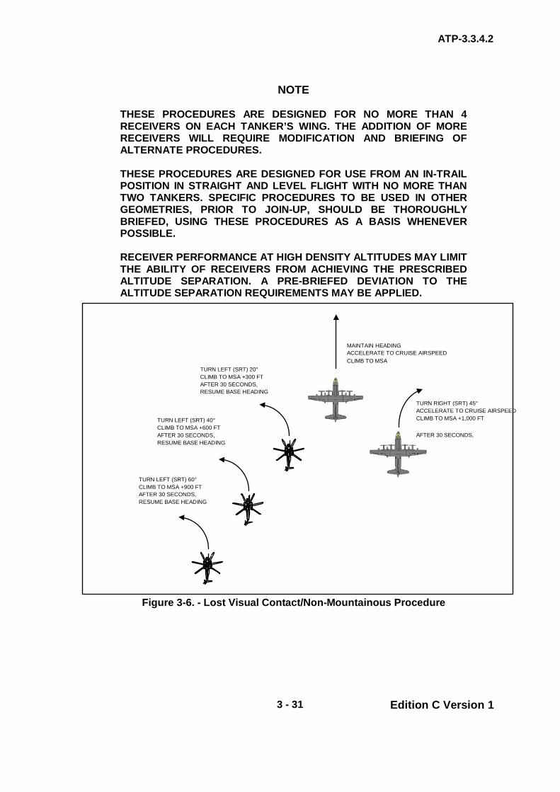
ATP-3.3.4.2
3 - 31 Edition C Version 1
NOTE
THESE PROCEDURES ARE DESIGNED FOR NO MORE THAN 4 RECEIVERS ON EACH TANKER’S WING. THE ADDITION OF MORE RECEIVERS WILL REQUIRE MODIFICATION AND BRIEFING OF ALTERNATE PROCEDURES. THESE PROCEDURES ARE DESIGNED FOR USE FROM AN IN-TRAIL POSITION IN STRAIGHT AND LEVEL FLIGHT WITH NO MORE THAN TWO TANKERS. SPECIFIC PROCEDURES TO BE USED IN OTHER GEOMETRIES, PRIOR TO JOIN-UP, SHOULD BE THOROUGHLY BRIEFED, USING THESE PROCEDURES AS A BASIS WHENEVER POSSIBLE. RECEIVER PERFORMANCE AT HIGH DENSITY ALTITUDES MAY LIMIT THE ABILITY OF RECEIVERS FROM ACHIEVING THE PRESCRIBED ALTITUDE SEPARATION. A PRE-BRIEFED DEVIATION TO THE ALTITUDE SEPARATION REQUIREMENTS MAY BE APPLIED.
Figure 3-6. - Lost Visual Contact/Non-Mountainous Procedure
MAINTAIN HEADING ACCELERATE TO CRUISE AIRSPEED CLIMB TO MSA
TURN RIGHT (SRT) 45° ACCELERATE TO CRUISE AIRSPEED CLIMB TO MSA +1,000 FT
AFTER 30 SECONDS,
TURN LEFT (SRT) 20° CLIMB TO MSA +300 FT AFTER 30 SECONDS, RESUME BASE HEADING
TURN LEFT (SRT) 40° CLIMB TO MSA +600 FT AFTER 30 SECONDS, RESUME BASE HEADING
TURN LEFT (SRT) 60° CLIMB TO MSA +900 FT AFTER 30 SECONDS, RESUME BASE HEADING

ATP-3.3.4.2
3 - 32 Edition C Version 1
Figure 3-7. - Lost Visual Contact/Simultaneous Refuelling/Non-Mountainous
Procedure
(1) Mountainous.
(a) Receiver Lose Sight. If the receiver(s) lose sight of each other or the lead aircraft (tanker):
(i) Receivers. The receivers will call:
“LOST VISUAL CONTACT” (ii) Tanker. The tanker will respond with:
“EXECUTE” followed by base heading and the MSA.
The tanker will then accelerate to cruise airspeed and climb to MSA to allow the receiver formation manoeuvring room.
(iii) Spare Tanker. The spare tanker will turn right 10°,
accelerate, and climb to MSA plus 1,000 ft and after 30 sec, resume base heading.
TURN LEFT (SRT) 40° CLIMB TO MSA +600 FT AFTER 30 SECONDS, RESUME BASE HEADING
MAINTAIN HEADING ACCELERATE TO CRUISE AIRSPEED CLIMB TO MSA

ATP-3.3.4.2
3 - 33 Edition C Version 1
(iv) First Receiver. The first receiver will maintain refuelling airspeed and climb to MSA plus 300 ft.
(v) Second Receiver. The second receiver will adjust
airspeed to air refuelling airspeed minus 10 KIAS and climb to MSA plus 600 ft.
(vi) Third Receiver. The third receiver will adjust
airspeed to air refuelling airspeed minus 20 KIAS and climb to MSA plus 900 ft.
(vii) Fourth Receiver. The fourth receiver will reduce
airspeed to air refuelling airspeed minus 30 KIAS and climb to MSA plus 1200 ft.
(viii) All Receivers. All receivers will maintain base
heading and hold their adjusted airspeed for 3 min after reaching their altitude. After 3 min, accelerate to HAAR airspeed (see Figure 3-8).
(b) Simultaneous Refuelling Operations. For simultaneous
refuelling operations, make the following changes to the procedures in (1) above: After “LOST VISUAL CONTACT” is called:
(i) First Receiver – Left Side. The first receiver on
the left side of the tanker will maintain air refuelling airspeed and climb to MSA plus 300 ft.
(ii) First Receiver – Right Side. The first receiver on
the right side of the tanker will adjust airspeed to air refuelling airspeed minus 10 KIAS and climb to MSA plus 600 ft.
(iii) Second Receiver – Left Side. The second
receiver on the left side of the tanker will adjust airspeed to air refuelling airspeed minus 20 KIAS and climb to MSA plus 900 ft.
(iv) Second Receiver – Right Side. The second
receiver on the right side of the tanker will adjust airspeed to air refuelling airspeed minus 30 KIAS and climb to MSA plus 1200 ft.
(v) All Receivers. All receivers will maintain base
heading and hold their adjusted airspeed for 3 min after reaching their altitude. After 3 min, accelerate to HAAR airspeed (see Figure 3-9).

ATP-3.3.4.2
3 - 34 Edition C Version 1
Figure 3-8. - Lost Visual Contact/Mountainous Procedure
TURN RIGHT 10° ACCELERATE TO CRUISE AIRSPEED CLIMB TO MSA +1,000 FT
AFTER 30 SECONDS,
MAINTAIN HEADING ACCELERATE TO CRUISE AIRSPEED CLIMB TO MSA
MAINTAIN AAR AIRSPEED CLIMB TO MSA +300 FT
MAINTAIN AAR AIRSPEED - 10 KIAS CLIMB TO MSA +600 FT
MAINTAIN AAR AIRSPEED -20 KIAS CLIMB TO MSA +900 FT
MAINTAIN AAR AIRSPEED - 30 KIAS CLIMB TO MSA +1200 FT
Note: All receivers will maintain base heading as relayed by the tanker and hold their adjusted airspeed for 3 minutes after reaching their altitude. After 3 minutes, accelerate to HAAR airspeed.

ATP-3.3.4.2
3 - 35 Edition C Version 1
Figure 3-9. - Lost Visual Contact/Mountainous Procedure
Option 2. - All aircraft in element 1, 2, or both per para. 3.26., or as briefed.
WARNING
THE SECOND ELEMENT AIRCRAFT MUST BE AWARE OF POSSIBLE MIDAIR COLLISION POTENTIAL WITH THE FIRST ELEMENT RECEIVERS. IF THE POTENTIAL FOR LOST CONTACT EXISTS WHEN EMPLOYING OPTION 2 FORMATION, INCREASING SEPARATION BETWEEN REFUELLING ELEMENTS SHOULD BE CONSIDERED.
MAINTAIN HEADING ACCELERATE TO CRUISE AIRSPEED CLIMB TO MSA
MAINTAIN AAR AIRSPEED CLIMB TO MSA +300 FT
MAINTAIN AAR AIRSPEED - 10 KIAS CLIMB TO MSA +600 FT
MAINTAIN AAR AIRSPEED - 30 KIAS CLIMB TO MSA +1200 FT
TURN RIGHT 10° ACCELERATE TO CRUISE AIRSPEED
CLIMB TO MSA +1,000 FT
MAINTAIN AAR AIRSPEED -20 KIAS CLIMB TO MSA +900 FT
Note: All receivers will maintain base heading as relayed by the tanker and hold their adjusted airspeed for 3 minutes after reaching their altitude. After 3 minutes, accelerate to HAAR airspeed.

ATP-3.3.4.2
3 - 36 Edition C Version 1
NOTE
WITHIN IN THE UNITED STATES, MOUNTAINOUS TERRAIN IS DEFINED BY FAR 95-11 PART B. OUTSIDE THE UNITED STATES, MOUNTAINOUS TERRAIN IS DEFINED AS HAVING A 500-FT CHANGE IN SURFACE ALTITUDE OVER 1/2 NM. ALL TURNS FOR BOTH MOUNTAINOUS AND NON-MOUNTAINOUS LOST VISUAL CONTACT PROCEDURES ARE EXECUTED USING A STANDARD RATE TURN (SRT). ALL HEADINGS ARE MAGNETIC AND ARE BASED ON THE HEADING ANNOUNCED BY THE TANKER AT THE INITIATION OF THE PROCEDURE. IN ALL CASES, THE BASE AIRSPEED IS THE PLANNED HAAR AIRSPEED. IF THE HAAR ALTITUDE IS ABOVE THE MSA, THE HAAR ALTITUDE WILL BE THE BASE FOR THE MANOEUVRE.
3.30. ABORT PROCEDURES Tankers will be prepared to assist receivers in the event of a receiver abort. Tankers will not abandon receivers that require navigation/communication assistance unless an emergency exists or a spare tanker is available. 3.31. AIRCRAFT MALFUNCTIONS
a. Tanker Engine Failure. Under conditions of high altitudes, ambient temperatures, and gross weights, the instantaneous loss of an engine may cause the tanker to yaw excessively and immediately lose airspeed. This may require maximum power on available engines, along with large rudder and aileron inputs. This may result in a mid-air collision and will require a breakaway.
CAUTION
LOST VISUAL CONTACT IN A MOUNTAINOUS ENVIRONMENT, ESPECIALLY AT LOW LEVEL, IS A CRITICAL SITUATION. THE TACTICAL ENVIRONMENT, EXISTING WEATHER CONDITIONS, AND TERRAIN MAY REQUIRE DEVIATIONS TO THE ABOVE PROCEDURES; THEREFORE, IT IS EXTREMELY IMPORTANT THAT THESE FACTORS BE THOROUGHLY BRIEFED DURING MISSION PLANNING.

ATP-3.3.4.2
3 - 37 Edition C Version 1
b. System Malfunctions. When a system malfunction jeopardizes safety, air refuelling will not be accomplished except during fuel emergencies or when continuation of refuelling is dictated by operational necessity. In the event a tanker malfunction occurs with a receiver(s) in contact, the tanker directs the receiver(s) to disconnect and remain outboard of the hose. Receiver(s) experiencing malfunctions should request disconnect (time permitting) and expect to move to the Echelon Left position.
c. Fuel Spray. A small amount of fuel spray may be present upon drogue
engagement/ disengagement. No fuel spray should be evident during fuel transfer. When fuel spray is noticed during fuel transfer, fuel flow will be stopped. The requirements to continue fuel transfer will be at the discretion of the receiver pilot.
3.32. BREAKAWAY PROCEDURES The conditions that require a breakaway include but are not limited to excessive receiver closure rates, receiver or tanker engine failure, and excessive fuel leak. When an emergency condition exists that requires immediate separation of aircraft, the tanker will call “BREAKAWAY, BREAKAWAY, BREAKAWAY” preceded by the tanker call sign and hose assignment pertaining to the receiver required to breakaway. Simultaneously, the tanker will turn on the lower anti-collision light (if refuelling un-aided). The receiver will effect a disconnect, manoeuvre clear of the astern position and await further instructions from the tanker.
CAUTION
THE RECEIVER DISCONNECT ANGLE (THE ANGLE BETWEEN THE HOSE COUPLING AND THE RECEIVER PROBE) MUST BE LIMITED TO (OR LESS THAN) 20 DEGREES OFF-CENTRE OR LESS DUE TO THE LIMITS OF THE HOSE COUPLING.
NOTE
OVERT ANTI-COLLISION LIGHTS MAY CAUSE EXCESSIVE GLARE DURING NVG OPERATIONS.
3.33. REDUCED RECEIVER FLIGHT PERFORMANCE If adequate power is unavailable (i.e. loss of an engine or high density altitude) a change to normal HAAR procedures may be required.
a. The helicopter will maintain the highest airspeed possible consistent with operating limitations outlined in the applicable flight manual and notify the tanker.
ATP-3.3.4.2
3 - 38 Edition C Version 1
b. Refuelling altitude will be 500 ft below receiver cruise altitude. c. Refuelling airspeed will be the tanker minimum speed or the receiver
airspeed, whichever is higher. d. The tanker will perform a receiver high RV. Execute the join-up to place
the receiver on the side of the tanker with the intended refuelling hose. e. The tanker will establish refuelling airspeed and set refuelling hoses
prior to reaching the receivers abeam position. f. As the nose of the tanker passes abeam, the helicopter will initiate a
shallow dive to accelerate and close on the tanker. The altitude differential should be sufficient to gain the additional airspeed required to manoeuvre into contact position.
g. Once contact is successfully completed, extra care should be taken to
take on the needed amount of fuel before disconnecting. There may not be enough power available to perform another contact and the tanker may not be able to loiter or escort and provide additional fuel at a later time.
NOTE
DUE TO THE ADDITIONAL POWER REQUIRED TO STABILISE IN THE ASTERN POSITION, THE RECEIVER IS TO MOVE DIRECTLY FROM AN EXTENDED HIGH ECHELON LEFT POSITION TO CONTACT WITHOUT A PAUSE IN THE ASTERN POSITION. ONCE ESTABLISHED IN THE REFUELLING POSITION, THE POWER REQUIRED TO STAY WITH THE TANKER WILL BE LESS THAN THAT REQUIRED TO MAINTAIN THE SAME AIRSPEED OUTSIDE THE TANKER’S DRAFTING EFFECT. CARE SHOULD BE TAKEN NOT TO LOSE AIRSPEED AS THERE IS INSUFFICIENT POWER AVAILABLE TO MANOEUVRE BACK INTO POSITION. TO REDUCE POWER REQUIREMENT, TOBOGGANING MAY BE REQUIRED.
3.34. LIGHTING Lighting configurations are specific to aircraft type/model. The appropriate National SRD should be consulted prior to conducting night HAAR operations.

ATP-3.3.4.2
3 - 39 Edition C Version 1
CHAPTER 3 ROTARY PROCEDURES SECTION V – COMMUNICATIONS
3.35. SECURITY It can be assumed that all HAAR frequencies will be subject to regular monitoring by potentially hostile agencies. Message originators are to ensure that classified information is not passed in an unclassified form. In particular, messages concerning airframe numbers, linkage of squadrons and locations, order of battle and associations of personnel with units are not to be transmitted. Tanker transmissions are liable to be intercepted, thus giving hostile forces knowledge of tanker positions and procedures; therefore, transmissions must be kept to a minimum. It will also be necessary on occasion to restrict the use of some or all aircraft electronic transmitting equipment. 3.36. COMMUNICATIONS IN MULTI-TANKER FORMATION The lead tanker crew is responsible for the formation communications. If special circumstances require, specific tasks may be delegated to other tankers in the formation. 3.37. MINIMUM COMMUNICATION REQUIREMENT Tankers and receivers will begin monitoring designated radio frequencies and will have electronic RV equipment operating no less than 10 min prior to ARCT. Communications capability between tanker and receiver will be maintained during the entire refuelling operation. Voice transmissions will be held to an absolute minimum during RV and HAAR in accordance with the EMCON option in use. Normally, radio transmissions between tanker and receiver aircraft will be conducted by pilots; however, any crewmember noting an emergency or hazardous situation may initiate breakaway procedures.
CAUTION
HAAR CONTACTS WILL NOT BE CONDUCTED WHEN RADIO COMMUNICATION CAPABILITY BETWEEN THE TANKER AND RECEIVER(S) IS LOST EXCEPT DURING EMERGENCY FUEL SITUATIONS OR CONTINGENCY OPERATIONS.

ATP-3.3.4.2
3 - 40 Edition C Version 1
3.38. MONITORING GUARD During HAAR, where radio equipment permits, tanker and receiver crews will maintain a listening watch on 243.00 MHz, this provides a guard frequency for receivers that need to join a tanker but do not know the HAAR control frequency. Furthermore, 243.00 MHz provides a guard frequency in the event of loss of radio contact between tanker and receiver. 3.39. REFUELLING FREQUENCY ASSIGNMENTS Identical refuelling frequencies (i.e. UHF/VHF, A/A TACAN, and IFF) will not be assigned to any two air refuelling operations being conducted in close enough proximity to cause a communication overlap. Each refuelling formation will be assigned a discrete primary and secondary frequency for the entire refuelling operation. 3.40. STANDARD HAAR TERMINOLOGY The following is considered standard HAAR terminology for both interphone communications for refuelling observers and inter-aircraft communications between receivers and tankers:
a. Receiver Abeam. b. Echelon (Left/Right). c. Astern (Left/Right). d. Contact (Left/Right). e. Disconnect/Inadvertent Disconnect (Left/Right). f. Receiver Clear (Left/Right). g. Crossover. h. Breakaway.
3.41. EMCON EMITTER PROCEDURES There may be a need to conduct HAAR training or operations with reduced electronic emissions. The controlling authority will promulgate the emission control (EMCON) option in force for the exercise/operation. The use of electronic emitters will vary according to the assessed threat. The definition of each EMCON option is given in Chapter 3, Annex 3I. Also, EMCON options and acceptable communications for each option are shown in Chapter 3 Annex 3I. This describes 4 levels of restriction on the use of electronic emissions and provides for further refined selection of transmitters.

ATP-3.3.4.2
3 - 41 Edition C Version 1
3.42. EMCON COMMUNICATION PROCEDURES There will be occasions when HAAR is conducted using agreed procedures and signalling facilities without the use of radio. For planned operational and training missions, the items detailed in Chapter 3, Annex 3A must be covered in the pre-flight briefing of both the tanker and receiver crews. EMCON communication procedures for HAAR are detailed in Chapter 3, Annex 5A. The occasions requiring EMCON 2-4 communication procedures are:
a. When directed by the EMCON option in force. b. When deemed tactically necessary or for training purposes agreed
between the tanker and receiver. c. In the event of radio failure. Refuelling following total radio failure should
only be undertaken when refuelling is essential due to the critical nature of the mission.
d. In the event that a receiver requires fuel but does not know the tanker’s
operating frequency. 3.43. ESCORT OPERATIONS During escort operations, the inbound tanker will RV with the escorting tanker on a UHF/VHF frequency other than that used by the primary tanker and receiver(s). 3.44. RADIO SILENT For EMCON Options 3 and 4, HAAR may be conducted for tactical training and operational missions provided the following precautions and procedures are observed:
a. The HAAR pre-RV briefing requirements will be covered in the pre-mission briefing.
b. Radio equipment on both aircraft must be operative and crews on both
aircraft must monitor the same frequency and GUARD (243.0 MHz) during all AAR procedures.
c. The RV requirements and altimeter setting are all briefed prior to the
mission.
NOTE
LIGHTS ON THE TANKER’S AAR PODS ARE AN INDICATION TO THE RECEIVER OF THE TANKER’S HYDRAULIC AND FUEL FLOW STATUS AND ARE NOT USED FOR EMCON COMMUNICATION.
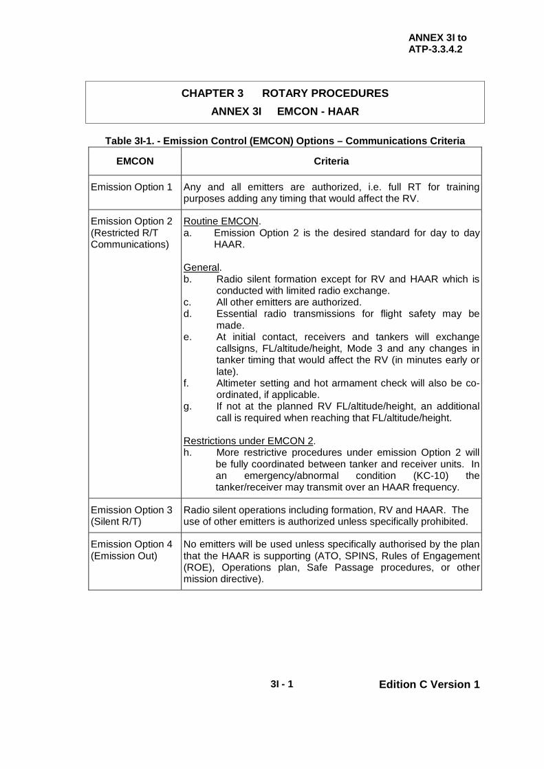
ANNEX 3I to ATP-3.3.4.2
3I - 1 Edition C Version 1
CHAPTER 3 ROTARY PROCEDURES ANNEX 3I EMCON - HAAR
Table 3I-1. - Emission Control (EMCON) Options – Communications Criteria
EMCON Criteria
Emission Option 1 Any and all emitters are authorized, i.e. full RT for training purposes adding any timing that would affect the RV.
Emission Option 2 (Restricted R/T Communications)
Routine EMCON. a. Emission Option 2 is the desired standard for day to day
HAAR. General. b. Radio silent formation except for RV and HAAR which is
conducted with limited radio exchange. c. All other emitters are authorized. d. Essential radio transmissions for flight safety may be
made. e. At initial contact, receivers and tankers will exchange
callsigns, FL/altitude/height, Mode 3 and any changes in tanker timing that would affect the RV (in minutes early or late).
f. Altimeter setting and hot armament check will also be co-ordinated, if applicable.
g. If not at the planned RV FL/altitude/height, an additional call is required when reaching that FL/altitude/height.
Restrictions under EMCON 2. h. More restrictive procedures under emission Option 2 will
be fully coordinated between tanker and receiver units. In an emergency/abnormal condition (KC-10) the tanker/receiver may transmit over an HAAR frequency.
Emission Option 3 (Silent R/T)
Radio silent operations including formation, RV and HAAR. The use of other emitters is authorized unless specifically prohibited.
Emission Option 4 (Emission Out)
No emitters will be used unless specifically authorised by the plan that the HAAR is supporting (ATO, SPINS, Rules of Engagement (ROE), Operations plan, Safe Passage procedures, or other mission directive).
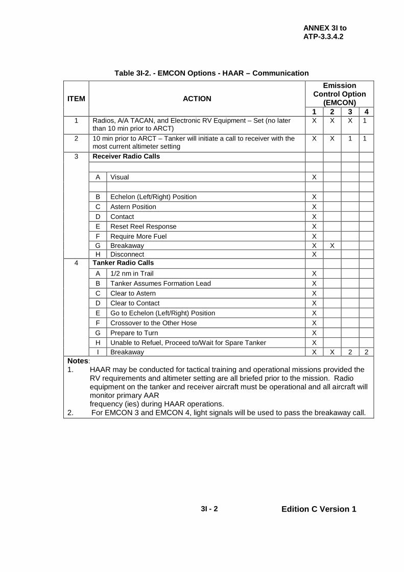
ANNEX 3I to ATP-3.3.4.2
3I - 2 Edition C Version 1
Table 3I-2. - EMCON Options - HAAR – Communication
ITEM ACTION
Emission Control Option
(EMCON) 1 2 3 4
1 Radios, A/A TACAN, and Electronic RV Equipment – Set (no later than 10 min prior to ARCT)
X X X 1
2 10 min prior to ARCT – Tanker will initiate a call to receiver with the most current altimeter setting
X X 1 1
3 Receiver Radio Calls A Visual X
B Echelon (Left/Right) Position X C Astern Position X D Contact X E Reset Reel Response X F Require More Fuel X G Breakaway X X H Disconnect X
4 Tanker Radio Calls A 1/2 nm in Trail X B Tanker Assumes Formation Lead X C Clear to Astern X D Clear to Contact X E Go to Echelon (Left/Right) Position X F Crossover to the Other Hose X G Prepare to Turn X H Unable to Refuel, Proceed to/Wait for Spare Tanker X I Breakaway X X 2 2
Notes: 1. HAAR may be conducted for tactical training and operational missions provided the
RV requirements and altimeter setting are all briefed prior to the mission. Radio equipment on the tanker and receiver aircraft must be operational and all aircraft will monitor primary AAR frequency (ies) during HAAR operations.
2. For EMCON 3 and EMCON 4, light signals will be used to pass the breakaway call.

ANNEX 3I to ATP-3.3.4.2
3I - 3 Edition C Version 1
Table 3I-3. Emission Options (HAAR) – Emitters
Item Equipment Emission Control Options
(EMCON) 1 2 3 4
1 Radar On On As Required Off
2 Doppler On On As Required Off
3 Beacon On On As Required Off
4 Radar Altimeter On On As Required Off
5 TACAN/DME On On As Required Off
6 IFF/Interrogator On On As Required Off
7 UHF/VHF/HF/SATCOM On On Monitor Monitor
8 ETCAS/TCAS On On As Required Off
9 ITS/LPI On On As Required Off
Note: Variations may be coordinated (e.g., “EMCON 2, EMITTERS, ITEM 1 OFF” would mean normal EMCON Option 2 procedures except the radar would be off).

ANNEX 3I to ATP-3.3.4.2
3I - 4 Edition C Version 1
Table 3I-4. HAAR Refuelling Light Signals (Sheet 1 of 2)
Tanker to Receiver
Item Tanker Light Signals
Meaning Receiver Response Multi Colour Single Colour
1 Upper anti-collision light secure
Upper anti-collision light secure
Tanker assumes lead Lead receiver secures strobe and proceeds to observation
2 One steady light (3) to receiver in observation
Cleared to astern and/or crossover
Stabilize in astern or crossover
3 One green light (3) to receiver in observation
Cleared to contact and/or crossover
Contact drogue or crossover
4 One steady light to receiver in astern
Cleared contact Contact drogue
5 One steady light to receiver in contact
Receiver has briefed offload, clear to disconnect
Disconnect and proceed to observation
6 Flashing light to receiver in contact
Tanker has malfunction
Disconnect and move outboard of hose
7 One steady light after item 6 or 16
Malfunction resolved, clear to contact
Contact drogue
8 Flashing light after item 6 or 16
Malfunction not resolved, proceed to observation
Proceed to observation
9 One white light Proceed to observation
Proceed to observation
10 Two white lights Momentary flash of top anti-collision light
Tanker directed crossover
Crossover to observation
11 One amber light Prepare to turn Do not attempt contact at night
12 Two amber lights Continuous light moved up and down
Tanker is unable to pass fuel; go to spare tanker
Proceed to spare
13 Multiple red lights and/or all pod status lights flashing
Anti-collision light on Breakaway: emergency exists
Disconnect and remain clear of the tanker
Primary Tanker to Spare Tanker
Item Tanker Light Signals
Meaning Spare Response Multi Colour Single Colour
14 Tanker flashes one white light (4)
Fuel Flowing Spare may retract hoses
15 Tanker flashes two white lights (4)
Unable to refuel Spare tanker is primary
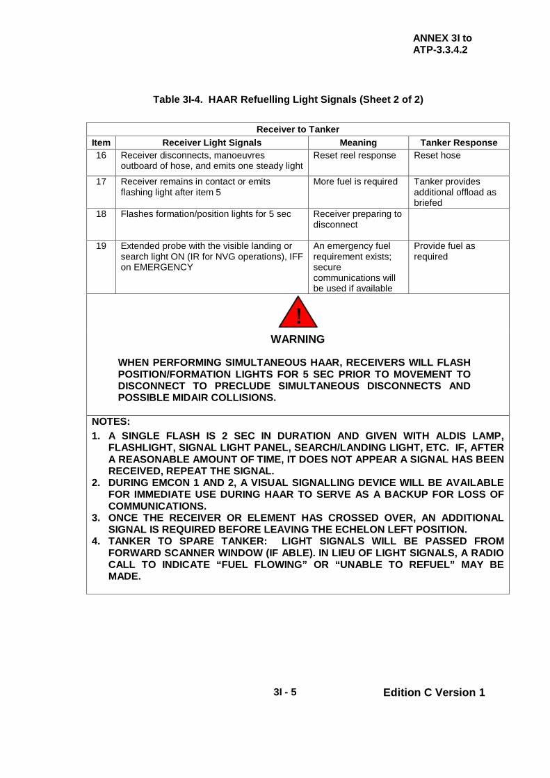
ANNEX 3I to ATP-3.3.4.2
3I - 5 Edition C Version 1
Table 3I-4. HAAR Refuelling Light Signals (Sheet 2 of 2)
Receiver to Tanker Item Receiver Light Signals Meaning Tanker Response 16 Receiver disconnects, manoeuvres
outboard of hose, and emits one steady light Reset reel response Reset hose
17 Receiver remains in contact or emits flashing light after item 5
More fuel is required Tanker provides additional offload as briefed
18 Flashes formation/position lights for 5 sec Receiver preparing to disconnect
19 Extended probe with the visible landing or search light ON (IR for NVG operations), IFF on EMERGENCY
An emergency fuel requirement exists; secure communications will be used if available
Provide fuel as required
WARNING
WHEN PERFORMING SIMULTANEOUS HAAR, RECEIVERS WILL FLASH POSITION/FORMATION LIGHTS FOR 5 SEC PRIOR TO MOVEMENT TO DISCONNECT TO PRECLUDE SIMULTANEOUS DISCONNECTS AND POSSIBLE MIDAIR COLLISIONS.
NOTES: 1. A SINGLE FLASH IS 2 SEC IN DURATION AND GIVEN WITH ALDIS LAMP,
FLASHLIGHT, SIGNAL LIGHT PANEL, SEARCH/LANDING LIGHT, ETC. IF, AFTER A REASONABLE AMOUNT OF TIME, IT DOES NOT APPEAR A SIGNAL HAS BEEN RECEIVED, REPEAT THE SIGNAL.
2. DURING EMCON 1 AND 2, A VISUAL SIGNALLING DEVICE WILL BE AVAILABLE FOR IMMEDIATE USE DURING HAAR TO SERVE AS A BACKUP FOR LOSS OF COMMUNICATIONS.
3. ONCE THE RECEIVER OR ELEMENT HAS CROSSED OVER, AN ADDITIONAL SIGNAL IS REQUIRED BEFORE LEAVING THE ECHELON LEFT POSITION.
4. TANKER TO SPARE TANKER: LIGHT SIGNALS WILL BE PASSED FROM FORWARD SCANNER WINDOW (IF ABLE). IN LIEU OF LIGHT SIGNALS, A RADIO CALL TO INDICATE “FUEL FLOWING” OR “UNABLE TO REFUEL” MAY BE MADE.

ANNEX 3I to ATP-3.3.4.2
3I - 6 Edition C Version 1
INTENTIONALLY BLANK

ATP-3.3.4.2
4 - 1 Edition C Version 1
CHAPTER 4 TILT ROTOR PROCEDURES SECTION I – PLANING AND BRIEFING CONSIDERATIONS
4.1. INTRODUCTION Tilt Rotor Air-to-Air Refuelling (TAAR) operations require precise and detailed planning to ensure safe and successful execution. Aircrews must be familiar with all the planning factors of TAAR operations including the capabilities and limitations of both receivers and tankers. The procedures employed and resultant performance may be neither the optimum nor the most efficient for either the tanker or receiver aircraft; however, they must conform to the operating limitations of each platform.
NOTE
USAF/AFSOC/USMC DIFFERENTIATES BETWEEN ECHELON AND OBSERVATION POSITIONS. THE ECHELON POSITION FOR FIXED WING AIRCRAFT IS STEPPED DOWN, AFT OF THE TANKER WINGLINE AND ONE RECEIVER WINGSPAN OUTBOARD OF THE TANKER WING. THE OBSERVATION POSITION IS A SPECIFIC TERM USED IN MC-130/KC-130 TANKER DROGUE & PROBE REFUELLING COMMUNITY INDICATING THE STABLE FORMATION POSITION OF RECEIVER AIRCRAFT, POST-JOIN, AND UTILIZED PRIOR TO SEQUENCING TO THE ASTERN POSITION.
WARNING
WHEN REFUELING FROM A KC-10 TANKER OR WHILE TANKING ABOVE MSA WITH USMC KC-130 ADHERE TO PROCEDURES IN ATP-56 CHAPTER 2 - FIXED WING PROCEDURES.
!
WARNING
SIMULTANEOUS TAAR OPERATIONS ARE NOT PERMITTED, HOWEVER, THE SIMULTANEOUS REFUELLING OF TILT ROTOR AIRCRAFT AND FIXED WING AIRCRAFT IS AUTHORISED.

ATP-3.3.4.2
4 - 2 Edition C Version 1
4.2. PLANNING CONSIDERATIONS
a. Fuel Transfer Rates. Transfer rates are normally 500-1000 lbs per minute; however, the rates are dependent on the tanker configuration. The specific National Annex should be consulted to determine the actual fuel transfer rate.
b. Hose Checks. If hose checks are required prior to conducting TAAR,
tanker aircrews should consider completing the checks prior to the rendezvous (RV) to avoid unnecessary delays. This may require tankers to plan to reduce airspeed en-route or transit via an en-route holding area.
c. TAAR Airspeed. For tankers equipped with the Variable Drag Drogue
(VDD) the Tilt Rotor AAR airspeed is 170 KCAS/KIAS (VDD allowable range is 160-180 KCAS/KIAS); for the High Speed Drogue (HSD) the airspeed is 200 KCAS/KIAS (HSD allowable range is 185-210 USAF, 185-250 USMC). When refuelling at speeds in excess of 200 KCAS, refer to the current MV-22 NATOPS for the maximum AAR speed.
d. TAAR Altitudes. The refuelling altitude must always consider terrain
and the tactical situation. The minimum AAR altitude is to be established in accordance with service or national directives. The maximum TAAR altitudes are to be established in accordance with the respective tanker and receiver performance.
e. TAAR Track. Whenever practicable, sufficient track length should be
planned to complete AAR without track reversals. The ARIP should be planned at a minimum of 10.5 NM prior to the ARCP. The ARIP forms part of the TAAR track and aids the tanker in identifying the receiver and determining their heading. Receivers are to plan to fly from the ARIP to the ARCP and then proceed along the TAAR track.
(1) Consideration should be given to the following when determining
TAAR track length:
(a) The ARCP is normally the earliest point the tanker can pass abeam the receiver (not when fuel is flowing).
(b) The amount of fuel to transfer. (c) The fuel transfer rate. (d) The number of tankers and receivers. (e) The hose time per receiver. (f) The ground speed. (g) Terrain.

ATP-3.3.4.2
4 - 3 Edition C Version 1
(h) Aircraft performance. (i) Routes of ingress and emergency egress.
(2) The planned track length should be adjusted for:
(a) Forecast Winds. (b) Higher true airspeeds. (c) Turbulence. (d) Multiple receivers. (e) Hose problems. (f) Orientation to the receiver’s capabilities and ingress and
egress routing.
(3) If the track length is insufficient and requires track reversal, due to terrain, threat, or mission parameters, careful attention must be given to turn radius and power considerations in the turns.
f. Tanker/Receiver Briefing Items. Tanker and receiver aircrews must
be familiar with the Tanker/Receiver Briefing Items when planning TAAR operations. All items should be briefed pre-flight otherwise briefed in-flight prior to the RV. The list is by no means prescriptive; aircrews should determine which are applicable and brief accordingly:
(1) Weather.
(a) Along Track and at Destination and Diversion. (b) Freezing level. (c) Cloud tops.
(2) Tanker and Receiver Callsigns. (3) Number of receivers/tankers. (4) Refuelling Formations.
(a) Option 1/Option 2. (b) Standby tanker requirements (in addition to Option 1/2
spare).

ATP-3.3.4.2
4 - 4 Edition C Version 1
(5) Communications Plan.
(a) AAR Primary and Secondary Frequencies. (b) Plain/Secure Voice. (c) EMCON option. (d) EMCON communications procedures. (e) Multi-colour light signals. (f) Single-colour light signals.
(6) The AAR Track (published name, if appropriate).
(a) Geo-reference (DATUM). (b) Receiver ingress routing. (c) AAR Initial Point (ARIP). (d) AAR Control Point (ARCP). (e) AAR Control Time (ARCT). (f) AAR track/course. (g) AAR airspeed. (h) Formation or individual defensive tactics. (i) Rejoin procedures. (j) AAR turn point(s). (k) ENDAR. (l) Abort point. (m) Abort criteria. (n) Divert routing/destination. (o) Emergency bases. (p) AAR exit point. (q) Air Traffic Control clearance limits.

ATP-3.3.4.2
4 - 5 Edition C Version 1
(r) Alternate track.
(7) AAR Altitudes.
(a) RV altitude (tanker). (b) Join up type and altitude (receiver high / low). (c) AAR altitude. (d) MSA (by leg if required). (e) Pre-planned Altimeter.
(8) RV Type. (9) Tanker No Show Procedures. (10) Receiver No Show Procedures. (11) Special Equipment.
(a) TACAN A/A channels. (b) Beacon. (c) IFF Setting/Interrogator Transponder System/Low
Probability Intercept (ITS/LPI).
(12) Fuel.
(a) Time on station available (b) Receiver requirements
(13) Receiver Disconnect procedures. (14) Tanker/Receiver lighting configuration and NVG considerations. (15) Lost Contact procedures. (16) Emergency procedures. (17) Lost Communications. (18) Performance limitations.

ATP-3.3.4.2
4 - 6 Edition C Version 1
4.3. TANKER/RECEIVER BRIEFING CARD To ensure all the mission detail has been communicated, a common mission briefing card should be developed for use by both tanker and receiver aircrews. An example briefing card is at Table 4.1.
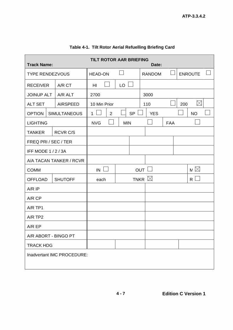
ATP-3.3.4.2
4 - 7 Edition C Version 1
Table 4-1. Tilt Rotor Aerial Refuelling Briefing Card
TILT ROTOR AAR BRIEFING Track Name: Date:
TYPE RENDEZVOUS HEAD-ON RANDOM ENROUTE
RECEIVER A/R CT HI LO
JOINUP ALT A/R ALT 2700 3000
ALT SET AIRSPEED 10 Min Prior 110 200
OPTION SIMULTANEOUS 1 2 SP YES NO
LIGHTING NVG MIN FAA
TANKER
RCVR C/S
FREQ PRI / SEC / TER
IFF MODE 1 / 2 / 3A
A/A TACAN TANKER / RCVR
COMM IN OUT M
OFFLOAD SHUTOFF each
TNKR R
A/R IP
A/R CP
A/R TP1
A/R TP2
A/R EP
A/R ABORT - BINGO PT
TRACK HDG
Inadvertant IMC PROCEDURE:

ATP-3.3.4.2
4 - 8 Edition C Version 1
INTENTIONALLY BLANK

ATP-3.3.4.2
4 - 9 Edition C Version 1
CHAPTER 4 TILT ROTOR PROCEDURES SECTION II – GENERAL PROCEDURES
4.4. GENERAL TAAR may be divided into four stages of operation: RV (intercept/escort), join-up, contact/fuel transfer, and post air refuelling. 4.5. WEATHER REQUIREMENTS
a. Altimeter Settings. Prior to the RV, every effort is to be made to obtain the most accurate altimeter setting available to ensure safe terrain clearance. In the absence of an accurate ground station observation, a forecast minimum altimeter setting/QNH or aircraft system-derived setting should be used unless the standard altimeter setting (1013 mb - 29.92 inches Hg) is required. Use of a forecast minimum altimeter setting will result in the greatest margin of safety. See Chapter 2, Section I, para. 1.2.a. for further details.
b. Visibility. The minimum visibility for a visual RV is 3 NM; for an
electronic RV the minimum visibility is 1 NM. Equipment with the capability to determine receiver range (e.g. Air-to-Air TACAN) is the minimum required for conducting an electronic RV. Equipment that provides range and bearing information (e.g. IFF interrogator or RADAR) meets the minimum requirement for an electronic RV.
c. Ceilings/Cloud Clearance. The minimum ceiling requirements should
be identified during the mission planning phase. National or service directives may dictate minimum weather requirements. It is recommended that the AAR altitude affords 1000ft of vertical clearance from the top or bottom of a broken/overcast (ceiling) during TAAR.
d. Cloud Avoidance. Flight through clouds after contact is to be avoided.
WARNING
FLIGHT INTO CLOUDS OR OBSCURATION AFTER RV MAY RESULT IN SPATIAL DISORIENTATION AND POTENTIAL MIDAIR COLLISION.
ATP-3.3.4.2
4 - 10 Edition C Version 1
Weather Watch. It is paramount to the success of TAAR operations that a single coordinated forecast is obtained by the commander or controlling agency (making go/no-go decisions). It is also imperative that a close weather watch be maintained to aid decision making throughout the operation. 4.6. RV PROCEDURES RV procedures provide the tanker with a means of transitioning from escort/intercept positions to a position 0.5 NM in trail of the receiver, prior to the join-up. Common to all types of TAAR RV, the tanker is to maintain a minimum of 500ft vertical separation from the receiver until positive visual contact is established, at which point the tanker can descend to the AAR altitude, once positioned on the AAR track. The tanker is to normally accomplish all required during the RV to preclude any degradation of the receiver’s performance and capability; the exception to this rule is the RV Echo (Tanker Orbit RV). The type of RV selected is dependent on the situation and is determined during mission planning. RV Delta, Echo, Foxtrot, Golf, and Hotel are the only RV types applicable to TAAR.
a. Communications. The receiver(s) and tanker(s) are to monitor Primary and Secondary AAR frequencies and is to have electronic RV equipment emitting (a minimum of) 10 min prior to ARCT. The Comm Plan and EMCON options are further discussed in Chapter 4 Section V.
(1) During initial radio contact (EMCON 1 and 2), tanker and receiver
aircrews are to confirm the altimeter setting and confirm any changes to the mission briefing.
(2) During EMCON 1 operations the tanker is to assume radio
control of the AAR evolution, after initial radio contact has been established between the tanker and receiver.
b. Arrival at ARCP. Both receivers and tankers should plan to arrive at the
ARCP on time; however, if a deviation is required, receivers should arrive at the ARCP early (no more than 1 minute) and tankers should arrive at the ARCP late (no more than 1 minute).
c. Receivers
(1) Join-Up Altitude. The Receiver is to be established at or below
the join-up altitude (above for receiver high) at a point no later than the ARIP, or at a previously briefed location. The join-up altitude is dependent on whether the join up is receiver high or receiver low.
(a) Receiver-Low Join. The join-up altitude is 300ft below
refuelling altitude for receiver-low operations. RV Echo, for USMC operations is 1000ft below refuelling altitude.

ATP-3.3.4.2
4 - 11 Edition C Version 1
(b) Receiver-High Join. The join-up altitude is 200 ft above refuelling altitude for receiver-high operations.
(2) Hot Armament Procedures. To prevent inadvertent weapons
firing during refuelling operations, receivers are to complete positive weapons checks in accordance with appropriate aircraft checklists prior to the tanker passing abeam during join-up.
(3) RV Airspeed. Receivers should maintain 180 KCAS from IP to
CP or until the tanker passes abeam on course for all overtaking RVs (B, D, G and H if appropriate).
d. Tankers
(1) Prior to RV. During the initial stage of the RV, standard intercept
procedures are to be employed to position the tanker on an intercept course with the receiver. The tanker is to perform the astern checklist in sufficient time to execute the selected RV procedure.
(2) Ingress Options. The tanker is to be established at the RV
altitude no later than the ARIP or within 5 NM of the receiver. Two options exist for the tanker ingress altitude prior to the RV:
(a) Ingress at AAR Altitude.
(i) During RV manoeuvring (range information only),
if the tanker does not have visual contact with the receivers prior to passing within 1 NM, the tanker should maintain a minimum of 500ft vertical separation or execute lost contact procedures.
(b) Ingress at RV altitude.
(i) Determining RV Altitude. The RV altitude
ensures vertical separation between tankers and receivers prior to positive visual contact. The RV altitude is based on the AAR altitude and is to be a minimum of 500ft above or below receiver join-up altitude depending on the type of join-up. For a receiver-low join-up, RV altitude is above AAR altitude. For a receiver-high join-up, RV altitude is below AAR altitude. RV altitude for receiver-low is defined as 200ft above refuelling altitude, 300ft below for receiver-high, until positive visual contact is established with the receivers.

ATP-3.3.4.2
4 - 12 Edition C Version 1
(ii) Prior to positive visual contact with the receivers, tankers should maintain the RV altitude. Once receivers are visually acquired, tankers may climb or descend to the refuelling altitude.
4.7. JOIN-UP PROCEDURES RV procedures position the tanker for join-up. The standard RV procedure conducted is a receiver-low for a left-hose join-up. Join-up procedures from all types of RV (with the exception of RV Echo) are the same and enable the tanker to proceed from 0.5 NM in trail (at refuelling altitude) to the lead position and establish refuelling configuration. The tanker must maintain a positive rate of closure to avoid delaying refuelling operations; however, caution must be exercised to avoid a receiver tail chase situation.
a. Change of Formation Lead. At close range (0.5 NM), the tanker may (in accordance with EMCON option) advise the receiver(s): “ONE-HALF NM IN TRAIL” and reduce airspeed to affect the join-up. The tanker is to initiate the contact checklist (if applicable) at the discretion of the pilot. As the nose of the tanker passes the receiver’s three o’clock position, the receiver is to be in the abeam position. The receiver is to then report: “VISUAL” in order to pass the lead. Normally, hoses are extended once the tanker has assumed the lead. Once the tanker has accepted the lead, the receivers may manoeuvre to the observation position.
b. Formation Lead Responsibilities. Once the tankers assume formation
lead, they are responsible for all navigation, weather avoidance, and position reporting. Communications?
4.8. Crossover/Cross Under After join-up, receivers are to be directed to the appropriate side of the tanker as required. A crossover or cross under may be utilized. If performing AAR with Fixed Wing and Tilt Rotor aircraft than the cross under shall be used.
a. Crossover. If a crossover is required, the receiver pilot is to move to the outside of the tanker wingtip, 100 ft aft of the horizontal stabilizer, and increase altitude to a minimum of 50 ft above the tanker’s vertical stabilizer. A crossover is to then be made by altering the receiver’s heading. During crossover, the receiver aircraft should be flown to a position outboard of the opposite wingtip aft of the horizontal stabilizer before descending into the opposite observation position. This procedure eliminates the possibility of the receiver passing through the area of turbulence directly behind the tanker.
b. Cross under. A cross under may also be utilized to move to the
opposite side of the tanker. The same procedures as a crossover are employed for a cross under, except to decrease altitude a minimum of 50 ft below that of the tanker’s altitude and keeping the tanker in sight at all times throughout the manoeuver.

ATP-3.3.4.2
4 - 13 Edition C Version 1
4.9. CONTACT/FUEL TRANSFER This section contains information to be used from the receiver’s arrival in the observation position until the completion of TAAR. The left side refuelling position is to be primary; however, either side may be used.
NOTE
CONTACTING AT NIGHT IN A TURN SHOULD BE CONDUCTED WITH DUE CONSIDERATION FOR THE INCREASED POTENTIAL FOR SPATIAL DISORIENTATION. IN TURBULENT CONDITIONS WHERE THE DROGUE IS TOO UNSTABLE FOR CONTACT, A TURN BY THE TANKER IN TURBULENT AIR IS TO TEND TO LOAD UP AND STABILIZE THE DROGUE. THE TANKER SHOULD ROLL INTO A ½ STANDARD RATE TURN OR LESS DURING THE MANEUVER.
a. Clear Astern. After completion of the contact checklist and when the
tanker is ready, the receiver is to be cleared to the astern position on the appropriate hose. A single clearance from the observation position to the contact position may be used if briefed, or is standard procedure in accordance with the tanker’s National Annex; however, all receivers is to stabilize in the astern position prior to attempting contact.
b. Clear for Contact. When the tanker is ready for contact, the receiver is
to be cleared for contact on the appropriate drogue. The receiver is to acknowledge this clearance (EMCON 1) and check that the tanker ready light is illuminated.
WARNING
CONTACTING A HOSE WITH NO HYDRAULIC PRESSURE IS AN EMERGENCY PROCEDURE ONLY. DURING ALL AAR WET TRANSFERS, IF THE SEARCH RADAR IS NOT REQUIRED FOR NAVIGATION OR WEATHER AVOIDANCE, PLACE THE RADAR FUNCTION SWITCH TO SECTOR/STANDBY AND DIRECT THE RADAR ENERGY AHEAD OF THE AIRCRAFT (EXCEPTION: AN/APN-241 RADAR).

ATP-3.3.4.2
4 - 14 Edition C Version 1
c. Hose Reset. When the receiver is clear and the tanker response set
switch is actuated, the hose in question is to be observed to travel to full trail and the tanker ready light is to illuminate. When cleared, the receiver may re-engage. If hose response is incorrect, the receiver is to be directed to a spare hose, if available.
CAUTION
THE RESPONSE RESET SWITCH MUST NEVER BE ACTUATED WITH THE RECEIVER ENGAGED, AS THIS COULD CAUSE LOSS OF ALL RESPONSE CAPABILITY.
CAUTION
EXCESSIVELY HARD CONTACT BETWEEN THE PROBE AND DROGUE CAN DAMAGE THE REFUELLING NOZZLE. SHOULD THE DROGUE BECOME UNSTABLE FROM PROBE CONTACT CAUSING SECTIONS OF THE CLOTH MATERIAL TO FAIL, IT IS POSSIBLE FOR THE DROGUE TO COLLAPSE AND FOR THE HOSE TO RETRACT FULLY INTO THE POD. CONTACT WITH A MALFUNCTIONING DROGUE THAT IS ROTATING AT GREATER THAN ONE REVOLUTION PER SECOND MAY DAMAGE THE PROBE NOZZLE LOCK RING; A CLOCKWISE ROTATING DROGUE COULD RESULT IN PARTIAL OR COMPLETE UNTHREADING OF THE PROBE NOZZLE. THEREFORE, CONTACTS WITH THIS TYPE OF DROGUE MALFUNCTION SHOULD BE RESTRICTED TO OPERATIONAL NECESSITY. WHEN EXCESSIVE HOSE SLACK AND WHIP OCCUR, OR A DEAD HOSE IS SUSPECTED, THE RECEIVER IS TO DISCONNECT BY BACKING OUT AND DISCONNECTING. AN EXCESSIVE RATE OF DISCONNECT IS TO ONLY AGGRAVATE ANY HOSE SINE WAVE MOTION.

ATP-3.3.4.2
4 - 15 Edition C Version 1
4.10. RECEIVER DISCONNECT To effect a normal disconnect, the receiver pilot is to reduce power and airspeed while maintaining the normal disconnect position (approximately 5 to 10ft above the contact position). This is to cause the receiver to move slowly back from the tanker and the refuelling hose to extend. A normal disconnect is to occur when the refuelling hose reaches its maximum extension.
CAUTION
OFF-CENTRE DISCONNECTS CAN DAMAGE THE REFUELLING NOZZLE.
a. Hose Unlock at Full Extension. Since fuel pressure is off at full hose extension, the locking action is released. More force is required to disengage than was required to engage as the locking rollers of the reception coupling must now travel up the steeply inclined rear surface of the probe head.
NOTE
DISCONNECT FORCE WITH A PRESSURIZED HOSE IS TO INCREASE TWO TO THREE TIMES ABOVE THE NOMINAL 420 LBS.
b. Tanker Actions after Disconnect. After disconnect, the tanker is to
maintain level flight and refuelling airspeed until the receiver(s) is confirmed clear.
4.11. AAR WITH ONE TANKER / TWO OR MORE RECEIVERS In the event more than one receiver is to be refuelled by a tanker, the join-up is to be performed as described in para. 4.7., with all receivers in left echelon formation. Refer to Figure 2-1.
a. Single Hose Procedures. When the number one receiver moves into the refuelling position, the next receiver is to maintain its extended echelon position behind and to the left/right of the tanker, leaving room for the refuelling receiver to return to the observation position if directed by the tanker. Upon completion of refuelling, the first receiver is to make a normal disconnect, per para. 4.10., move aft and clear of the tanker, and either rejoin the formation in the last (most rearward) position or establish a right echelon formation as each subsequent receiver completes the AAR. This procedure is to be repeated until all receivers have been refuelled. Using either procedure and upon completion of all

ATP-3.3.4.2
4 - 16 Edition C Version 1
formation refuelling, the first receiver is to assume the lead position either in left or right observation position to the tanker.
b. Alternating Refuelling Procedures.
(1) When cleared by the tanker, receivers designated to refuel on the
tanker’s right side is to cross over/under to the right observation position.
(2) If the tanker is ready to begin refuelling, the receivers on the left
side may be cleared for contacts prior to the second element crossing over/under to the right observation position.
NOTE
RECEIVERS DESIGNATED TO REFUEL ON THE RIGHT HOSE MAY CROSS OVER/UNDER INDIVIDUALLY, IN SEQUENTIAL ORDER, OR SIMULTANEOUSLY AS A FORMATION ELEMENT. FORMATION CROSSOVERS/UNDERS REQUIRE CONSIDERABLE ADDITIONAL POWER FOR WINGMEN IN THE ELEMENT SINCE THEY MUST MOVE FROM ECHELON LEFT FORMATION TO THE ECHELON RIGHT PRIOR TO THE ELEMENT LEADER REACHING THE RIGHT OBSERVATION POSITION.
NOTE
ALTHOUGH TILT ROTOR PLATFORMS DO NOT SIMULTANEOUSLY REFUEL, THE FORMATION MAY SPLIT TO BOTH HOSES AS DESCRIBED ABOVE TO EXPEDITE THE REFUELLING PROCESS.
4.12. MULTIPLE DRY CONTACTS (TRAINING)
a. Request for Multiple Dry Contacts. If not previously briefed, receivers may request multiple dry contacts by stating:
“REQUEST MULTIPLE DRY CONTACTS ON THE LEFT (OR RIGHT).”
The tanker is to approve multiple dry contacts by stating:
“CLEARED FOR MULTIPLE DRY CONTACTS ON THE LEFT (OR RIGHT).”
b. Cessation of Multiple Dry Contacts. This series of manoeuvres,
contacts and disconnects may be continued at the discretion of the receiver pilot until the clearance for multiple dry contacts is cancelled or the receiver requests clearance to the observation position.
ATP-3.3.4.2
4 - 17 Edition C Version 1
4.13. COMPLETION OF AAR
a. Disconnect. When fuel transfer is completed, the tanker is to clear the receiver to disconnect unless otherwise briefed for self-clearing. The receiver is to disconnect as described in para. 4.10.
b. Formation Element Rejoin. When both receiver elements have
completed AAR operations, the receiver formation rejoin can be executed, prior to or after tanker departure, as briefed.
c. Formation Rejoin. After disconnect, receiver aircraft rejoin in the
Echelon Left or Right position in a Left or Right Echelon formation. After the flight is joined, the flight may climb or descend to a tactical altitude, exercising caution not to drift under a tanker with extended hoses.
d. Formation Break-up. When the receiver(s) call clear of the tanker, the
tanker is to retract the hoses and accelerate away from the receiver flight. Both tanker and receiver(s) are to ensure adequate separation prior to initiating any turns.
4.14. EN ROUTE/ESCORT PROCEDURES The information contained in this section is to apply when two or more platforms are involved in an en-route formation with subsequent AAR. If more specific instructions are necessary, they should be included in an operations order. Refer to AFSOCH 11-222 for optional CV-22 specific long-range escort procedures.
NOTE
DURING ESCORT OPERATIONS, INBOUND TANKERS ARE TO COORDINATE WITH THE ESCORTING TANKER ON A DISCRETE FREQUENCY.
a. Formation Escort. Under certain conditions (i.e. long flights over water,
desolate terrain, weather avoidance), the receiver(s) may require escort. The situation is to dictate the escort procedures; however, the following methods should be considered:
(1) Method 1. The tanker is to be 1000ft above (or below) and 1 to 2
NM in trail behind the receivers. (2) Method 2. The tanker is to be 1000ft above (or below) in the lead
position 1 to 2 NM ahead of the receivers. (3) Method 3. The tanker assumes the formation lead and all of the
receivers maintain formation off the tanker's wing.

ATP-3.3.4.2
4 - 18 Edition C Version 1
NOTE
THE ESCORTING TANKER MAY BE TASKED WITH WEATHER RECONNAISSANCE. IN CERTAIN SITUATIONS, THE TANKER MAY BE REQUIRED TO DETACH FROM THE RECEIVERS(S) AND PROCEED DOWN COURSE TO BETTER FACILITATE THIS TASK. IN THIS EVENT, TANKERS ARE TO AFFECT A NORMAL RV UPON THEIR RETURN AND RESUME ESCORT DUTIES USING THE OPTIONS LISTED ABOVE.
b. Refuelling During Escort Mission. If refuelling is to be conducted
during the escort mission, the ARCT is to be planned such that all receivers are to be refuelled (or in the process of refuelling) prior to the abort point.
(1) Prior to initiating join-up from the escort position, the tanker is to
complete all appropriate checklists and direct the receiver(s) to climb/descend to join-up altitude. The tanker is to proceed to refuelling altitude after the receiver(s) report “level.”
(2) Upon completion of fuel transfer, when the receiver(s) is clear,
the tanker is to accelerate away from the receiver flight. Both tanker and receiver(s) are to ensure adequate separation prior to initiating any turns.
c. Replacement Tanker. If the requirement exists for a replacement tanker
to RV with the AAR formation en-route, it is to do so at least 30 minutes prior to abort time, or as briefed. It is to remain 1000ft above the escort or refuelling altitude (whichever is higher) until all aircraft in the formation are in sight. Once in sight, the replacement tanker should position itself 1 to 2 NM behind the trail aircraft in the formation. When the primary tanker has completed refuelling and has departed the formation, the replacement tanker is to assume duties/position as the escort.
4.15. ON-CALL (UNPLANNED) TAAR Some tactical situations may require receivers to request TAAR with little or no planning. Examples include “Texaco,” anchor tracks, en-route track procedures, and off-track manoeuvring. On-call TAAR may be accomplished on established anchor tracks, at a series of pre-planned points/routes, on an extension of an existing TAAR track, or on unplanned points or tracks. Tanker crews must have a thorough understanding of receiver(s) mission requirements and routing before accepting an on-call TAAR.
a. Requesting On-Call TAAR. Receivers are to use the brevity term “Texaco” to request an on-call AAR. The receiver is to relay to the tanker the ARCP coordinates/waypoint identifier, range and bearing from BULLSEYE (or other known/pre-briefed position), ARCT, track heading, requested fuel, and the number of receivers. Tanker aircrews, after
ATP-3.3.4.2
4 - 19 Edition C Version 1
examining the terrain along track, are to compute and relay refuelling altitude, MSA, and time status to receivers.
b. Terrain Avoidance. Crews are to have calculated the MSA and
recommended refuelling altitude prior to join-up on any on-call track. Tanker aircrews are responsible for maintaining terrain clearance on track and are to recompute track heading and refuelling altitude as the terrain or threat dictate.
4.16. RV FROM A GROUND LAAGER In certain instances, the receiver may be so low on fuel that they opt to land to conserve fuel. The following may be used as a guide when setting up tactical RV procedures from a ground laager. Receivers are to confirm with the tankers the exact procedure to be used.
a. Land with sufficient fuel to allow for a shutdown, start and RV with the tanker.
b. Determine the track heading and select an ARCP approx. 10 NM from
the receiver’s ground laager location. c. Pass the ARCP coordinates/waypoint, track heading and requested
onload to the refuelling coordinator. d. The tanker is to calculate the ARCT and pass to the receiver. e. The tanker is to fly over the receiver’s position on the prearranged track
at the refuelling altitude with hoses extended, ready for contact. f. Tanker is to give an advisory call at 10 min prior to arriving at the ARCT. g. Upon departure, receivers are to immediately climb to join-up altitude
and accelerate to refuel airspeed in order to meet the ARCT. h. Conduct standard join-up and refuel procedures. i. If the receiver(s) cannot make the ARCT, the tanker may arrive
overhead the receiver location, establish contact configuration, and continue to orbit whilst waiting for the receiver(s). Once airborne the receiver is to proceed on a briefed heading and altitude to RV with the tanker.

ATP-3.3.4.2
4 - 20 Edition C Version 1
4.17. NO-SHOWS
a. Receiver No-Shows. If the receiver(s) have not been acquired (visually, electronically or through voice communication) prior to the ARIP, the tankers are to proceed to the ARCP at RV airspeed and altitude and establish a left-hand orbit, planning each circuit to arrive back at the ARCP at 8-minute intervals (“rules of 8”). Further actions are to be mission dependent and should be briefed to both the tanker and receiver crews. The “rules of 8” is to provide a means of adjusting the timeline for both the tanker and the receiver.
b. Tanker No-Shows. If no contact, voice, visual or electronic, is
established between the receiver and the tanker by the ARCP, the receiver(s) is to proceed to the ARCP at RV airspeed and altitude and establish a left-hand orbit at the ARCP, planning each circuit to arrive at the ARCP in 8-minute intervals (“rules of 8”). Further actions are to be mission dependent and should be briefed to both the tanker and receiver crews.
4.18. TYPES OF RV
a. RV Alpha (Anchor RV). Not used for TAAR. b. RV Bravo (Head-on). Not used for TAAR. c. RV Charlie. Not used for TAAR. d. RV Delta (Head-on offset). The head-on offset RV is the most
frequently used procedure and may be performed electronically (minimum visibility of 1 NM) or visually (minimum visibility of 3 NM); RV Delta details are at Chapter 4 Annex 4D.
e. RV Echo (Tanker Orbit). This is the only RV in which the receiver
manoeuvres to affect the RV and join-up; RV Echo details are at Chapter 4 Annex 4E.
f. RV Foxtrot (Sequenced). This RV procedure is normally conducted
when the tanker(s) and receiver(s) are operating from the same airfield. The tanker and receiver aircraft depart within a few minutes of each other and proceed together as a formation; RV Foxtrot details are published at Chapter 4 Annex 4F.
g. RV Golf (En route). RV Golf involves the tanker approaching the
receiver from the rear once visual (minimum visibility 3 NM) or electronic (minimum visibility 1 NM) contact has been established; details are at Chapter 4 Annex 4G.
h. RV Hotel (Random). The RV Hotel is used during VMC as a method to
facilitate an RV without losing visual contact with the receiver(s); details are published at Chapter 4 Annex 4H.

ANNEX 4A to ATP-3.3.4.2
4A - 1 Edition C Version 1
CHAPTER 4 TILT ROTOR PROCEDURES ANNEX 4A RV ALPHA
Not used for TAAR.

ANNEX 4B to ATP-3.3.4.2
4B - 1 Edition C Version 1
CHAPTER 4 TILT ROTOR PROCEDURES ANNEX 4B RV BRAVO (HEAD-ON)
Not used for TAAR.

ANNEX 4C to ATP-3.3.4.2
4C - 1 Edition C Version 1
CHAPTER 4 TILT ROTOR PROCEDURES ANNEX 4C RV CHARLIE
Not used for TAAR.
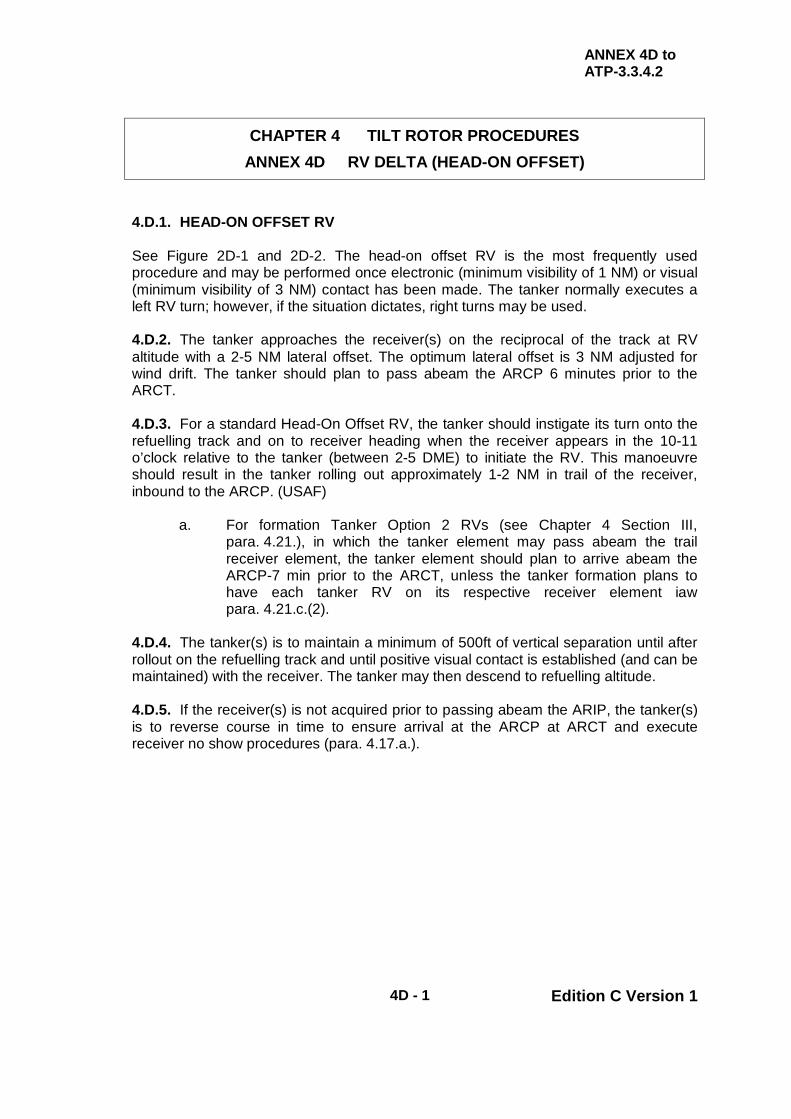
ANNEX 4D to ATP-3.3.4.2
4D - 1 Edition C Version 1
CHAPTER 4 TILT ROTOR PROCEDURES ANNEX 4D RV DELTA (HEAD-ON OFFSET)
4.D.1. HEAD-ON OFFSET RV See Figure 2D-1 and 2D-2. The head-on offset RV is the most frequently used procedure and may be performed once electronic (minimum visibility of 1 NM) or visual (minimum visibility of 3 NM) contact has been made. The tanker normally executes a left RV turn; however, if the situation dictates, right turns may be used. 4.D.2. The tanker approaches the receiver(s) on the reciprocal of the track at RV altitude with a 2-5 NM lateral offset. The optimum lateral offset is 3 NM adjusted for wind drift. The tanker should plan to pass abeam the ARCP 6 minutes prior to the ARCT. 4.D.3. For a standard Head-On Offset RV, the tanker should instigate its turn onto the refuelling track and on to receiver heading when the receiver appears in the 10-11 o’clock relative to the tanker (between 2-5 DME) to initiate the RV. This manoeuvre should result in the tanker rolling out approximately 1-2 NM in trail of the receiver, inbound to the ARCP. (USAF)
a. For formation Tanker Option 2 RVs (see Chapter 4 Section III, para. 4.21.), in which the tanker element may pass abeam the trail receiver element, the tanker element should plan to arrive abeam the ARCP-7 min prior to the ARCT, unless the tanker formation plans to have each tanker RV on its respective receiver element iaw para. 4.21.c.(2).
4.D.4. The tanker(s) is to maintain a minimum of 500ft of vertical separation until after rollout on the refuelling track and until positive visual contact is established (and can be maintained) with the receiver. The tanker may then descend to refuelling altitude. 4.D.5. If the receiver(s) is not acquired prior to passing abeam the ARIP, the tanker(s) is to reverse course in time to ensure arrival at the ARCP at ARCT and execute receiver no show procedures (para. 4.17.a.).
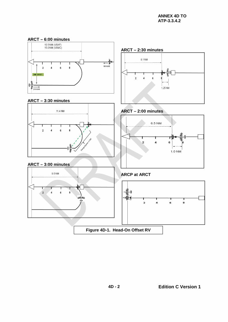
ANNEX 4D TO ATP-3.3.4.2
4D - 2 Edition C Version 1
ARCT – 6:00 minutes
ARCT – 3:30 minutes
ARCT – 3:00 minutes
ARCT – 2:30 minutes
ARCT – 2:00 minutes ARCP at ARCT
Figure 4D-1. Head-On Offset RV

ANNEX 4D TO ATP-3.3.4.2
4D - 3 Edition C Version 1
Figure 4D-2. Head-On Offset RV (USMC)

ANNEX 4D TO ATP-3.3.4.2
4D - 4 Edition C Version 1
Figure 4D-2 continued. Head-On Offset RV (USMC)

ANNEX 4D TO ATP-3.3.4.2
4D - 5 Edition C Version 1
INTENTIONALLY BLANK
ANNEX 4E to ATP-3.3.4.2
4E - 1 Edition C Version 1
CHAPTER 4 TILT ROTOR PROCEDURES ANNEX 4E RV ECHO (TANKER ORBIT)
4.E.1. TANKER ORBIT RV (VMC ONLY) See Figure 2E-1. This is the only RV in which the receiver manoeuvres the aircraft to affect the RV and join-up. Whilst the tanker is to normally maintain refuelling airspeed, receivers may request the tanker to adjust airspeed in order to facilitate a faster join-up. 4.E.2. The tanker maintains the orbit at a specified location arriving over the ARCP at briefed intervals.
a. The standard orbit consists of 11-12 NM (3 min) legs with one 1/2 standard rate turn at the end of each leg. This results in one complete orbit every 10 min. Crews may adjust the size of the orbit according to mission requirements; however, tankers should strive to arrive over ARCP at the briefed interval, starting at ARCT. Orbits of non-standard duration should be described as RV-E 15, 20, etc., where the number identifies the time between tanker arrivals over ARCP.
b. An alternate tanker orbit consists of the tanker orbiting around a pre-
briefed, fixed point while maintaining a constant bank turn (usually 20° angle of bank). This orbit allows the tanker to maintain refuelling airspeed and configuration to expedite refuelling operations. The receiver uses turn radius cut-off to affect the RV.
4.E.3. The receiver(s) is to maintain a minimum 500 ft of vertical separation until the tanker is in visual contract. In order to facilitate combined FAAR and TAAR, a vertical separation of 1000ft is to be used for USMC operations. 4.E.4. Once the tanker is in visual contact, the receiver is cleared to join in the left observation position. Once the receiver has commenced the join-up, the tanker should maintain a constant turn until the join-up is complete. When the join-up is complete, the tanker is to proceed as briefed.

ANNEX 4E to ATP-3.3.4.2
4E - 2 Edition C Version 1
Figure 4E-1 - Tanker Orbit RV

ANNEX 4F to ATP-3.3.4.2
4F - 1 Edition C Version 1
CHAPTER 4 TILT ROTOR PROCEDURES ANNEX 4F RV FOXTROT
4.F.1. The RV Foxtrot is a sequenced departure normally used in VMC conditions when the tanker(s) and receiver(s) are operating from the same airfield. The tanker and receiver take-off within a few minutes of each other, which may provide fuel savings not available in other RV procedures. This sequenced departure has the added advantage that it is usually possible for the tanker to delay its take-off until assured of the receiver’s serviceability on start up. However, adverse climb-out weather or ATC considerations may make these procedures impracticable. Coordination with the appropriate controlling agency may be required. There are two methods of affecting a RV Foxtrot: the Accompanied Departure/Buddy Climb and the Tailchase. 4.F.2. ACCOMPANIED DEPARTURE / BUDDY CLIMB In this procedure (see Fig. 2F-1) the tanker(s) takes off before the receiver and completes a visual circuit of the airfield whilst the receiver(s) takes off; the tanker(s) then joins formation with the receiver(s) in the climb. 4.F.3. ACCOMPANIED DEPARTURE / BUDDY CLIMB - PLANNING CONSIDERATIONS The weather conditions are a significant factor in the decision to employ this RV vice a Tailchase Departure. The cloud ceiling and visibility must allow for a VMC pattern for the tanker to be able to join with the receiver. 4.F.4. ACCOMPANIED DEPARTURE / BUDDY CLIMB - IMPLEMENTATION The Accompanied Departure/Buddy Climb is accomplished by:
a. Receiver/Tanker Departure. Because airspace reservations are usually based on the tanker flight plan, the tanker take-off time is a critical planning factor.
b. Tanker Visual Circuit. The tanker(s) takes off ahead of the receiver(s),
and flies a visual circuit. The receiver(s) takes off when the tanker is established on the downwind leg in the visual pattern.
c. Receiver Departure. The receiver(s) carries out a standard departure;
the tanker(s) continues the visual circuit, adjusting speed and track to join the receiver(s) in the climb.

ANNEX 4F to ATP-3.3.4.2
4F - 2 Edition C Version 1
Figure 4F-1. - Accompanied Departure/Buddy Climb 4.F.5. TAILCHASE DEPARTURE In this procedure, the receiver(s) takes off before the tanker(s). 4.F.6. TAILCHASE DEPARTURE - PLANNING CONSIDERATIONS Planning should reflect that, as the receivers launch first, should one or more receivers fail to get airborne, the tanker is to normally continue as planned accompanied by the reduced number of receivers. 4.F.7. TAILCHASE DEPARTURE - ESTABLISHING ARIP The standard method for co-ordinating this departure is to establish an ARIP after the receiver’s top of climb; the tanker and receiver take-off times are adjusted to meet the ARIP at the ARCT. This departure is suited to when weather conditions are relatively poor at the airfield or during the initial stages of the climb. If, however, the weather conditions are favourable, the take-off times can be planned in order that the tanker(s) join-up with the receiver(s) in the climb. 4.F.8. TAILCHASE DEPARTURE - IMPLEMENTATION A thorough pre-flight briefing between the tanker and receiver aircrews is essential.
a. ARIP. The receiver aircrew calculates their top of climb position and establishes the ARIP, one minute along-track from the top of climb position. A direct climb-out from base is preferable but not essential.

ANNEX 4F to ATP-3.3.4.2
4F - 3 Edition C Version 1
b. ARCT. The ARCT is calculated from the receiver take-off time. c. Take-Off Time - Tanker. The tanker aircrew calculates its take-off time
in order to meet the ARIP and compares the receivers’ take-off time to ensure adequate separation.
d. Vertical Separation - Tanker. As soon as practical after take-off, the
tanker is to establish RT contact with the receiver(s). The tanker is to ensure that its passing FL/altitude/height is at least 1000ft below that of the receiver until positive visual identification is made.
e. Rate of Climb. An agreed common rate of climb is to be pre-briefed. f. Height Calls - Tanker. Following the initial RT contact, the receiver is to
call the FL/altitude/height level every 1000ft until the tanker is in visual contact; this also assists the tanker in maintaining vertical separation. Should IMC be encountered by either aircraft prior to the join-up, more frequent height comparisons are to be made to ensure the necessary vertical separation is maintained.
g. Orbiting - Tanker. If the tanker has not confirmed visual contact during
the climb, the receivers are to make good the ARIP and, with ATC agreement, establish a left hand orbit until join-up is complete.
4.F.9. TANKER DEPARTS BEFORE RECEIVER The tanker(s) may depart ahead of the receiver(s). In such cases, the procedures listed above remain valid, although the lead formation assumes responsibility for height calls. Once VMC, the formation is to co-ordinate, with ATC, a 1000ft separation between receivers and tankers. Additionally, if the receivers are unable to accelerate and overtake the tanker, the tanker should reduce airspeed as necessary or arrange, with ATC, a left hand orbit in order to acquire the receivers.

ANNEX 4F to ATP-3.3.4.2
4F - 4 Edition C Version 1
INTENTIONALLY BLANK

ANNEX 4G to ATP-3.3.4.2
4G - 1 Edition C Version 1
CHAPTER 4 TILT ROTOR PROCEDURES ANNEX 4G RV GOLF (EN ROUTE)
4.G.1. EN ROUTE (OVERTAKING) RV See Figure 2G-1 and 2G-2. The tanker approaches the receiver from the rear using visual (minimum visibility 3 NM) or electronic (minimum visibility 1 NM) means. The procedures outlined in para. 4.14. apply. 4.G.2. The tanker and receiver(s) may arrive over the ARIP from different directions; however, their course from ARIP to ARCP is to be the same. 4.G.3. The tanker is to maintain a minimum of 500ft vertical separation until positive visual contact with the receiver is established and can be maintained. The tanker may then descend to refuelling altitude. 4.G.4. If receivers are not acquired prior to passing the ARCP, the tanker(s) shall ensure arrival at the ARCP at ARCT and execute receiver no show procedures (para. 4.17.a.).
Figure 4G-1. - Enroute (Overtaking) RV (USAF)

ANNEX 4G to ATP-3.3.4.2
4G - 2 Edition C Version 1
Figure 4G-2. - Enroute (Overtaking) RV (USMC)

ANNEX 4H to ATP-3.3.4.2
4H - 1 Edition C Version 1
CHAPTER 4 TILT ROTOR PROCEDURES ANNEX 4H RV HOTEL (RANDOM)
4.H.1. RANDOM RV The RV Hotel (Random RV) does not make use of a prescribed pattern or procedure. RV Hotel is used during VMC as a method to facilitate an RV without losing visual contact with the receiver(s). The tanker pilot should position his aircraft to maintain visual contact. This procedure is designed to expedite RV, to maintain visual contact once established and to allow the tanker pilot to manoeuvre the tanker as required to accomplish a successful RV. 4.H.2. The tanker is to establish RV altitude at least 5 NM from the receiver(s) and maintain this altitude until visual contact is established. The tanker is to:
a. Confirm receiver(s) is at join-up altitude.
b. With receiver(s) in sight, descend/climb to refuelling altitude (as required) and manoeuvre to 0.5 NM in trail and proceed with join-up procedures.

ANNEX 4H to ATP-3.3.4.2
4H - 2 Edition C Version 1
INTENTIONALLY BLANK

ATP-3.3.4.2
4- 20 Edition C Version 1
CHAPTER 4 TILT ROTOR PROCEDURES SECTION III – FORMATION PROCEDURES
4.19. FORMATION OPTIONS The refuelling formations described within this chapter are designed for missions requiring multiple tankers but does not include all possible tanker/receiver formations. Furthermore planners should consider these procedures when refuelling multiple receivers. Both tanker and receiver aircrews must be well versed in these procedures for them to be effective; any deviations from these procedures must be coordinated with all participants. The tanker RV typically starts with tankers in a trail formation. During the RV, tankers adjust their formation in order to arrive abeam the receivers. 4.20. FORMATION OPTION 1 Formation Option 1 (Figure 4-1) consists of two tankers: one primary and one spare. This formation is ideally suited for refuelling up to four receivers with the receivers refuelling from the primary tanker.
a. Spare Tanker Positioning. The spare tanker maintains its position as described in para. 4.22.
b. Transition to Spare Tanker. The transition to the spare tanker position
is described in para. 4.23. c. Completion of Refuelling. After refuelling is complete, the primary
tanker is to maintain refuelling airspeed until the spare tanker rejoins in Echelon Right. The formation is to then proceed as briefed.
4.21. FORMATION OPTION 2 (TRAIL) Formation Option 2 (Figure 4-2) consists of at least two primary tankers and one spare tanker, when available. This formation is ideally employed when supporting more than four receivers.
a. Receiver Element Spacing. Prior to reaching the ARIP, the receiver flight separates into two elements in trail. The standard spacing between Tilt Rotor receiver elements is 1NM, however, it may be as close as 0.5 NM and should be determined by mission requirements; number of receivers, terrain, forecast visibility, and light conditions. Non-standard spacing is to be specifically briefed. When utilising TACAN A/A to conduct the RV, all distance references should be made from the lead receiver of the lead element. Using the lead receiver as the reference simplifies the RV and alleviates the requirement for multiple TACAN A/A channels. The ARCT is the control time for arrival of the lead receiver element at the ARCP.

ATP-3.3.4.2
4- 21 Edition C Version 1
b. Tanker Formation Positions. Tanker aircraft typically execute the RV using the trail formation. When employing formations of two or three aircraft, the No. 1 and No. 2 primary tankers assume the lead and dash 2 positions. If there is a spare tanker, it assumes the dash 3 position. When employing formations of four aircraft (two primary and two spares), the first element consists of the No. 1 primary tanker and No. 1 spare; the second element consists of the No. 2 primary tanker and No. 2 spare. See Figure 4-2.
c. Join-Up. There are two methods that can be used to affect the join-up.
In either case, once the join-up is complete, the No. 2 tanker element should adjust its position (vertically/laterally) as required to account for turbulence from the lead element.
(1) Method 1. The tankers maintain formation until they approach
the second receiver element (trailing element). At this point, the No. 2 element lead primary tanker (and spare, if applicable) drops out of the formation and completes the join-up on the trail receiver element. The lead primary tanker (and spare, if applicable) continues forward to join-up on the lead receiver element.
(2) Method 2. Prior to the ARIP, the primary tankers establish
spacing between themselves that is equal to the briefed spacing between receiver elements. If one spare tanker is available, it remains with the No. 2 primary element lead tanker. If two spares are available, they remain with their respective primary. From this point, they execute individual join-ups on their respective elements.
4.22. SPARE TANKER POSITIONING
a. Formation Position. Prior to join-up, the spare tanker(s) formates in the Echelon Right position approximately 500 to 2,000ft of its respective primary tanker.
b. Vertical Position. The vertical position of the spare tanker, in reference
to the primary, is generally co-altitude. The decision to assume a stepped-up or stepped-down position (approximately 50 ft) is dependent on the refuelling altitude, visibility, and ease of maintaining the correct position to observe signals from the lead tanker.
c. Transition to Spare Position. The transition to the spare position
should be completed early enough to allow the primary tanker latitude in manoeuvring and airspeed changes during RV.
d. Configuration of Spare Tanker. The spare tanker(s) configures its
hoses at the same time as its respective primary element lead tanker.
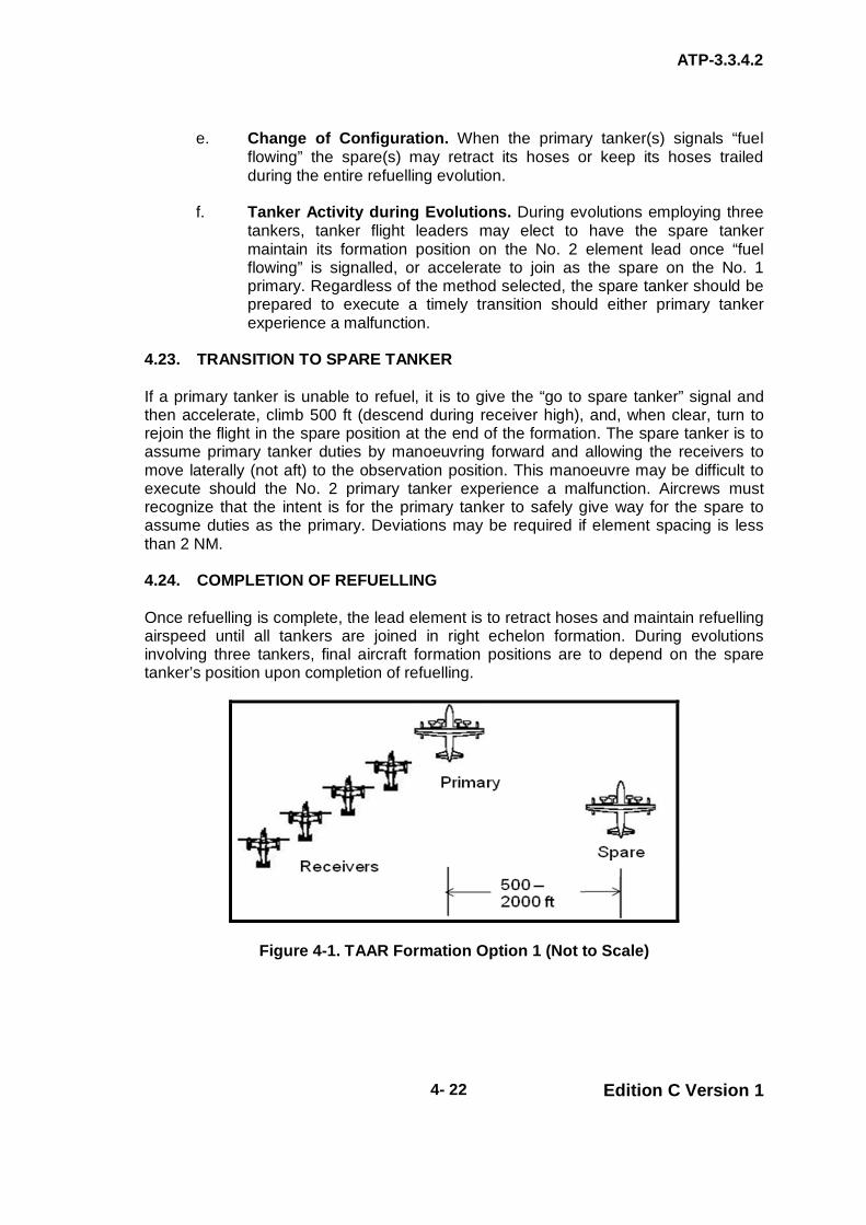
ATP-3.3.4.2
4- 22 Edition C Version 1
e. Change of Configuration. When the primary tanker(s) signals “fuel flowing” the spare(s) may retract its hoses or keep its hoses trailed during the entire refuelling evolution.
f. Tanker Activity during Evolutions. During evolutions employing three
tankers, tanker flight leaders may elect to have the spare tanker maintain its formation position on the No. 2 element lead once “fuel flowing” is signalled, or accelerate to join as the spare on the No. 1 primary. Regardless of the method selected, the spare tanker should be prepared to execute a timely transition should either primary tanker experience a malfunction.
4.23. TRANSITION TO SPARE TANKER If a primary tanker is unable to refuel, it is to give the “go to spare tanker” signal and then accelerate, climb 500 ft (descend during receiver high), and, when clear, turn to rejoin the flight in the spare position at the end of the formation. The spare tanker is to assume primary tanker duties by manoeuvring forward and allowing the receivers to move laterally (not aft) to the observation position. This manoeuvre may be difficult to execute should the No. 2 primary tanker experience a malfunction. Aircrews must recognize that the intent is for the primary tanker to safely give way for the spare to assume duties as the primary. Deviations may be required if element spacing is less than 2 NM. 4.24. COMPLETION OF REFUELLING Once refuelling is complete, the lead element is to retract hoses and maintain refuelling airspeed until all tankers are joined in right echelon formation. During evolutions involving three tankers, final aircraft formation positions are to depend on the spare tanker’s position upon completion of refuelling.
Figure 4-1. TAAR Formation Option 1 (Not to Scale)

ATP-3.3.4.2
4- 23 Edition C Version 1
Figure 4-2. - TAAR Formation Option 2 with Three Tankers (Not to Scale)
ATP-3.3.4.2
4 - 24 Edition C Version 1
CHAPTER 4 TILT ROTOR PROCEDURES SECTION IV – SAFETY PROCEDURES
4.25. INTRODUCTION The foundation for the safe conduct of TAAR, by national or multi-national forces, is standard, simple and unambiguous procedures. With these criteria established, multi-national TAAR is practicable by day and night, and during periods of EMCON constraint. 4.26. UNAIDED TAAR (NON-NVG)
a. RV. For RV, both the lead and trail receiver are to display a strobe.
b. Join-Up.
(1) Receivers. Receiver(s) are to have lighting configured no later than the ARIP.
(2) Tankers. During join-up, the tanker is to set refuelling lights no
later than 0.5 NM in trail of the receiver(s). (3) Post Join-Up. After join-up, the trailing receiver is to display the
strobe for the formation. If conducting refuelling with a spare tanker, the spare tanker will display the strobe for the formation.
(4) Crossover/Cross under. If required, the receiver is to ensure
that the top (including vertical stabilizer) or bottom of the tanker can be clearly determined prior to commencing the crossover. If requested by the receiver the tanker is to turn on its strobe/anti-collision light, or increase the intensity of formation strip lighting, to assist receivers in maintaining vertical clearance. The tanker is to secure the strobe/anti-collision light once the crossover is complete.
WARNING
SOME TANKERS HAVE THE UPPER STROBE LOCATED ON THE TOP OF THE FUSELAGE AT THE WING ROOT. RECEIVERS MUST ENSURE ADEQUATE SPACING IS MAINTAINED FROM THE TANKER’S UNLIT VERTICAL STABILIZER DURING CROSSOVER.

ATP-3.3.4.2
4 - 25 Edition C Version 1
c. Contact/Fuel Transfer.
(1) The Tilt Rotor has a probe light for unaided operations but may
not sufficiently illuminate the drogue to safely accomplish AAR without other tanker covert or overt pod and hose illumination lighting.
(2) For EMCON 2-4 TAAR, receivers are to flash their
formation/position lights 5 seconds prior to movement for disconnect. This procedure may be briefed otherwise for single hose operations.
4.27. Aided TAAR (NVG) The tactical/training situation dictates the use of aircraft lighting for TAAR. The following is recommended for aided (NVG) operations:
a. RV.
(1) The lead Tilt Rotor is to have prop rotor tip lights on and the trail receiver is to display the strobe.
(2) For tanker formations, the lead tanker should use an NVG
compatible anti-collision light for the RV; the trail tanker should display the anti-collision light for the formation (if required) until required to assume primary tanker duties.
WARNING
THE OPERATION OF AN OVERT ANTI-COLLISION LIGHT(S) BY THE ELEMENT LEAD WHILE IN LOW-LIGHT LEVEL CONDITIONS MAY INDUCE OR INCREASE THE POSSIBILITY FOR SPATIAL DISORIENTATION WITHIN FLIGHT ELEMENTS. EXTREME VIGILANCE AND CARE ARE REQUIRED BY WINGMEN TO MINIMIZE THIS EFFECT. AIRCREWS SHOULD NOT HESITATE TO REQUEST THE LEAD’S OVERT ANTI-COLLISION LIGHT(S) BE EXTINGUISHED IF FLIGHT SAFETY IS JEOPARDIZED.
b. Join-Up.
(1) Receiver(s) are to have lighting configured no later than ARIP.
(2) During join-up, the tanker is to set refuelling lights no later than 0.5 NM in trail.

ATP-3.3.4.2
4 - 26 Edition C Version 1
NOTE
OVERT ANTI-COLLISION LIGHTS MAY CAUSE EXCESSIVE GLARE DURING NVG JOIN-UPS.
c. Refuelling.
(1) After join-up, the trailing receiver or spare tanker (if available) is
to display the anti-collision light for the formation. (2) During alternating, or simultaneous if conducting concurrent
Fixed Wing AAR, refuelling operations with no spare tanker, one of the trail receivers (on either side) is to display the anti-collision light. Normally this is the last aircraft in the receiver element.
(3) For EMCON 2-4 TAAR, receivers are to flash their
formation/position lights 5 sec prior to movement for disconnect. This procedure may be briefed otherwise for single hose operations.
NOTE
DURING TAAR TRAINING IN LOW-LIGHT LEVEL CONDITIONS, THE REFUELLING OBSERVER MAY BE UNABLE TO PERFORM HIS DUTIES WHEN THE RECEIVER IS REQUIRED TO CARRY AN ANTI-COLLISION LIGHT. IF FLIGHT SAFETY IS COMPROMISED, THE TANKER AIRCRAFT COMMANDER IS TO TERMINATE TAAR OPERATIONS. DURING MULTI-SHIP TAAR, RECEIVERS THAT ARE NOT REFUELLING MAY DISPLAY THE ANTI-COLLISION LIGHT FOR THE FLIGHT WITHOUT AFFECTING THE TAAR EVOLUTION. DURING NVG TAAR OPERATIONS, THE REFUELLING OBSERVERS ARE TO BE AIDED; HOWEVER, THE TANKER COCKPIT CREW MAY NOT BE AIDED. THE NVG CAPABILITY OF THE TANKER(S) IS TO BE COVERED IN THE MISSION BRIEF.
4.28. JOIN-UPS - SAFETY CONSIDERATIONS
a. To complete a safe join-up, the receiver is to achieve a stable formation position (i.e., zero rate of closure) on the tanker before manoeuvring to the astern position. Stable formation must be achieved in a position where an error of judgment in the join-up does not lead to a collision risk with the tanker.
b. Longitudinal distance from the tanker and rate of closure from behind
are the most difficult features to assess, particularly at night; therefore, a direct join-up to a position behind the tanker is not to be attempted.

ATP-3.3.4.2
4 - 27 Edition C Version 1
c. Accordingly, all join-ups are to be made to the left observation position; thus errors in line and overtake speed can be corrected clear of the tanker.
4.29. LOST CONTACT PROCEDURES
a. Prior to Tanker Assuming Formation Lead.
(1) Within 3 NM of Receiver.
(a) Loss of Visual and Electronic Contact - Tanker. If visual and electronic contact is lost after the tanker is within 3 NM of the receiver, the tanker is to:
(i) Immediately call:
“CONTACT LOST”
(ii) Turn right 10°or more if feasible from track
heading to establish a minimum 1 NM lateral separation from the refuelling track.
(iii) Establish a minimum 500 ft vertical separation (if
able or conditions permit) and
(iv) Slow to AAR airspeed
(v) After 30 sec, resume track heading, and manoeuvre for another RV or proceed as briefed.
(b) Loss of Visual Contact, Electronic Contact Maintained
– Tanker. If visual contact is lost but electronic contact is maintained, the tanker is to maintain current altitude and continue join-up. At 1 NM electronic contact, if visual contact is not established. The tanker is to:
(i) Slow to AAR airspeed (ii) Call:
“NO VISUAL CONTACT”
(iii) Maintain electronic contact 1-2 NM in trail of
receiver(s) until positive visual contact is re-established or proceed as briefed.
(c) Actions of Spare Tanker. During “no visual contact” or
“contact lost” the spare tanker is to stay with the lead tanker. If the spare tanker loses sight of lead, the spare tanker is to:

ATP-3.3.4.2
4 - 28 Edition C Version 1
(i) Turn right 20° or more from the lead tanker’s
heading and climb 700 feet above refuelling altitude.
(ii) Slow to AAR airspeed. (iii) Maintain electronic contact with lead tanker and
manoeuvre for rejoin when able (Fig 4-3).
(2) Within 1 NM of Receiver
(a) Loss of Visual Contact. Under any circumstances if the tanker is within 1 NM of the receiver(s) and loses visual contact, the tanker is to immediately:
(i) Establish a minimum of 500 ft vertical separation
(if able or conditions permit). (ii) Slow to AAR airspeed. (iii) Call:
“NO VISUAL CONTACT”
(iv) Turn right 10°or more if feasible from track
heading to establish a minimum 1 NM lateral separation from the refuelling track.
(v) After 30 sec, manoeuvre for another RV or
proceed as briefed (Fig 4-3).
(b) Actions of Spare Tanker. The spare tanker is to stay with the lead tanker. If the spare tanker loses sight of the lead tanker, the spare tanker is to:
(i) Turn right 20° or more from the lead tanker’s
heading and climb 700 ft above refuelling altitude. (ii) Slow to AAR airspeed. (iii) Maintain electronic contact with lead tanker and
manoeuvre for rejoin when able (Fig 4-3).
b. After Tanker Assumes Formation Lead-Formation Below MSA (Fig 4-4)

ATP-3.3.4.2
4 - 29 Edition C Version 1
NOTE
THESE PROCEDURES ARE DESIGNED FOR NO MORE THAN 4 RECEIVERS ON EACH TANKER’S WING. THE ADDITION OF MORE RECEIVERS IS TO REQUIRE MODIFICATION AND BRIEFING OF ALTERNATE PROCEDURES. THESE PROCEDURES ARE DESIGNED FOR USE FROM AN IN-TRAIL POSITION IN STRAIGHT AND LEVEL FLIGHT WITH NO MORE THAN TWO TANKERS. SPECIFIC PROCEDURES TO BE USED IN OTHER GEOMETRIES, PRIOR TO JOIN-UP, SHOULD BE THOROUGHLY BRIEFED, USING THESE PROCEDURES AS A BASIS WHENEVER POSSIBLE. RECEIVER PERFORMANCE AT HIGH DENSITY ALTITUDES MAY LIMIT THE ABILITY OF RECEIVERS FROM ACHIEVING THE PRESCRIBED ALTITUDE SEPARATION. A PRE-BRIEFED DEVIATION TO THE ALTITUDE SEPARATION REQUIREMENTS SHOULD BE APPLIED.
(1) Receiver(s) Lose Sight. If the receiver(s) lose sight of each
other or the lead aircraft (tanker):
(a) Receivers. The receivers are to call:
“LOST VISUAL CONTACT”
(b) Tanker. The tanker is to respond with:
“EXECUTE” followed by the base heading and the MSA.
The tanker is to then accelerate to cruise airspeed and climb to MSA to allow the receiver formation manoeuvring room.
(c) Spare Tanker. The spare tanker is to turn right 10°,
accelerate to cruise airspeed, and climb to MSA plus 1,000 ft and after 30 sec, resume base heading.
(d) First Receiver. The first receiver is to maintain refuelling
airspeed and climb to MSA plus 500 ft. (e) Second Receiver. The second receiver is to adjust
airspeed to air refuelling airspeed minus 10 KIAS and climb to MSA plus 1000 ft.
(f) Third Receiver. The third receiver is to adjust airspeed to
air refuelling airspeed minus 20 KIAS and climb to MSA plus 1500 ft.

ATP-3.3.4.2
4 - 30 Edition C Version 1
(g) Fourth Receiver. The fourth receiver is to reduce airspeed to air refuelling airspeed minus 30 KIAS and climb to MSA plus 2000 ft.
(h) All Receivers. All receivers are to maintain base heading
and hold their adjusted airspeed for 3 min after reaching their altitude. After 3 min, all receivers are to accelerate to AAR airspeed (see Figure 4-4).
(2) Simultaneous/Alternating Refuelling Operations Below MSA.
(Fig 4-5). For simultaneous/alternating refuelling operations, the following changes are made to the procedures in (1) above: After “LOST VISUAL CONTACT” is called:
(a) First Receiver – Left Side. The first receiver on the left
side of the tanker is to maintain air refuelling airspeed and climb to MSA plus 500 ft.
(b) First Receiver – Right Side. The first receiver on the
right side of the tanker is to adjust airspeed to air refuelling airspeed minus 10 KIAS and climb to MSA plus 1000 ft.
(c) Second Receiver – Left Side. The second receiver on
the left side of the tanker is to adjust airspeed to air refuelling airspeed minus 20 KIAS and climb to MSA plus 1500 ft.
(d) Second Receiver – Right Side. The second receiver on
the right side of the tanker is to adjust airspeed to air refuelling airspeed minus 30 KIAS and climb to MSA plus 2000 ft.
(e) All Receivers. All receivers are to maintain base heading
and hold their adjusted airspeed for 3 min after reaching their altitude. After 3 min, all receivers are to accelerate to AAR airspeed (see Figure 4-5).
c. After Tanker Assumes Formation Lead-Formation Above MSA: Due to
the possibility of simultaneous tanker operations with fixed wing aircraft, reference Fixed Wing procedures (ATP-56 Chapter 2 Section IV, para. 2.30.) for procedures to be executed when tanker operations take place above MSA. (Figure 4-6)

ATP-3.3.4.2
4 - 31 Edition C Version 1
Figure 4-3. Contact Lost / No Visual Contact (Not to Scale)
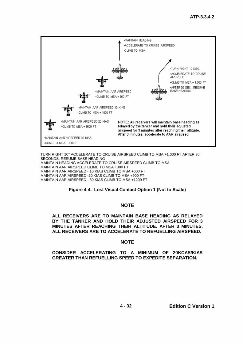
ATP-3.3.4.2
4 - 32 Edition C Version 1
TURN RIGHT 10° ACCELERATE TO CRUISE AIRSPEED CLIMB TO MSA +1,000 FT AFTER 30 SECONDS, RESUME BASE HEADING MAINTAIN HEADING ACCELERATE TO CRUISE AIRSPEED CLIMB TO MSA MAINTAIN AAR AIRSPEED CLIMB TO MSA +300 FT MAINTAIN AAR AIRSPEED - 10 KIAS CLIMB TO MSA +600 FT MAINTAIN AAR AIRSPEED -20 KIAS CLIMB TO MSA +900 FT MAINTAIN AAR AIRSPEED - 30 KIAS CLIMB TO MSA +1200 FT
Figure 4-4. Lost Visual Contact Option 1 (Not to Scale)
NOTE
ALL RECEIVERS ARE TO MAINTAIN BASE HEADING AS RELAYED BY THE TANKER AND HOLD THEIR ADJUSTED AIRSPEED FOR 3 MINUTES AFTER REACHING THEIR ALTITUDE. AFTER 3 MINUTES, ALL RECEIVERS ARE TO ACCELERATE TO REFUELLING AIRSPEED.
NOTE CONSIDER ACCELERATING TO A MINIMUM OF 20KCAS/KIAS GREATER THAN REFUELLING SPEED TO EXPEDITE SEPARATION.

ATP-3.3.4.2
4 - 33 Edition C Version 1
Figure 4-5. Lost Visual Contact Option 2 (Not to Scale)
WARNING
LOST VISUAL CONTACT IN A MOUNTAINOUS ENVIRONMENT, ESPECIALLY AT LOW LEVEL, IS A CRITICAL SITUATION. THE TACTICAL ENVIRONMENT, EXISTING WEATHER CONDITIONS, AND TERRAIN MAY REQUIRE DEVIATIONS TO THE ABOVE PROCEDURES; THEREFORE, IT IS EXTREMELY IMPORTANT THAT THESE FACTORS BE THOROUGHLY BRIEFED DURING MISSION PLANNING.
NOTE
WITHIN IN THE UNITED STATES, MOUNTAINOUS TERRAIN IS DEFINED BY FAR 95-11 PART B. OUTSIDE THE UNITED STATES, MOUNTAINOUS TERRAIN IS DEFINED AS HAVING A 500-FT CHANGE IN SURFACE ALTITUDE OVER 0.5 NM.
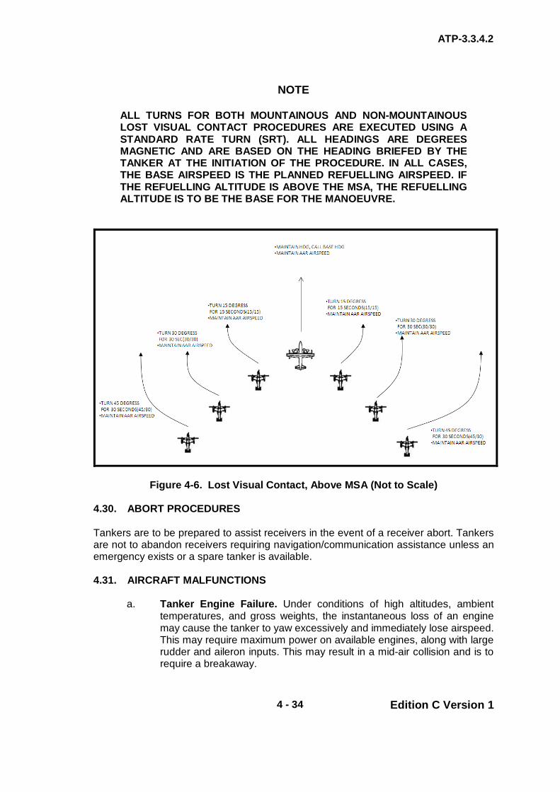
ATP-3.3.4.2
4 - 34 Edition C Version 1
NOTE
ALL TURNS FOR BOTH MOUNTAINOUS AND NON-MOUNTAINOUS LOST VISUAL CONTACT PROCEDURES ARE EXECUTED USING A STANDARD RATE TURN (SRT). ALL HEADINGS ARE DEGREES MAGNETIC AND ARE BASED ON THE HEADING BRIEFED BY THE TANKER AT THE INITIATION OF THE PROCEDURE. IN ALL CASES, THE BASE AIRSPEED IS THE PLANNED REFUELLING AIRSPEED. IF THE REFUELLING ALTITUDE IS ABOVE THE MSA, THE REFUELLING ALTITUDE IS TO BE THE BASE FOR THE MANOEUVRE.
Figure 4-6. Lost Visual Contact, Above MSA (Not to Scale) 4.30. ABORT PROCEDURES Tankers are to be prepared to assist receivers in the event of a receiver abort. Tankers are not to abandon receivers requiring navigation/communication assistance unless an emergency exists or a spare tanker is available. 4.31. AIRCRAFT MALFUNCTIONS
a. Tanker Engine Failure. Under conditions of high altitudes, ambient temperatures, and gross weights, the instantaneous loss of an engine may cause the tanker to yaw excessively and immediately lose airspeed. This may require maximum power on available engines, along with large rudder and aileron inputs. This may result in a mid-air collision and is to require a breakaway.

ATP-3.3.4.2
4 - 35 Edition C Version 1
b. System Malfunctions. When a system malfunction jeopardizes safety, AAR is to not be undertaken except during fuel emergencies or when continuation of refuelling is dictated by operational necessity. In the event of a tanker malfunction whilst with a receiver(s) in contact, the tanker is to direct the receiver(s) to disconnect and remain outboard of the hose. Receiver(s) experiencing malfunctions are to request disconnect (time permitting) and are expected to manoeuvre to the observation position.
c. Fuel Spray. A small amount of fuel spray may be present upon drogue
engagement/ disengagement. No fuel spray should be evident during fuel transfer. When fuel spray is noticed during fuel transfer, fuel flow is to be stopped. The requirements to continue fuel transfer is to be at the discretion of the receiver pilot.
4.32. BREAKAWAY PROCEDURES The conditions that require a breakaway include (but are not limited to) excessive receiver closure rates, receiver or tanker engine failure, and excessive fuel leak. During an emergency that requires the immediate separation of aircraft, the tanker is to call “BREAKAWAY, BREAKAWAY, BREAKAWAY” preceded by the tanker call sign and hose assignment pertaining to the receiver required to breakaway. Simultaneously, the tanker is to turn on the lower anti-collision light (if refuelling un-aided). The receiver is to disconnect, manoeuvre clear of the astern position, and await further instructions from the tanker.
WARNING
THE RECEIVER DISCONNECT ANGLE (THE ANGLE BETWEEN THE HOSE COUPLING AND THE RECEIVER PROBE) MUST BE LIMITED TO (OR LESS THAN) 20 DEGREES OFF-CENTRE DUE TO THE LIMITS OF THE HOSE COUPLING.
NOTE
OVERT ANTI-COLLISION LIGHTS MAY CAUSE EXCESSIVE GLARE DURING NVG OPERATIONS.

ATP-3.3.4.2
4 - 36 Edition C Version 1
4.33. REDUCED RECEIVER FLIGHT PERFORMANCE If adequate power is unavailable (i.e. loss of an engine or high density altitude) a change to normal TAAR procedures may be required.
a. The receiver is to maintain the highest airspeed possible consistent with operating limitations outlined in the applicable flight manual and notify the tanker.
b. The refuelling altitude will be a minimum of 500 ft below receiver cruise
altitude. c. The refuelling airspeed will be the tanker minimum speed or the receiver
airspeed, whichever is higher. d. The tanker is to perform a receiver high RV and execute the join-up to
place the receiver on the side of the tanker with the intended refuelling hose.
e. The tanker is to establish at refuelling airspeed and set the refuelling
hoses prior to reaching abeam the receivers position. f. At any time the receiver pilot may ask for a toboggan to either assist with
the contact manoeuvre or during contact. The tanker is to initiate and maintain a 300 fpm descent during the toboggan.
g. Once contact is successfully completed, extra care should be taken to
take on the needed amount of fuel before disconnecting. There may not be enough power available to perform another contact and the tanker may not be able to loiter or escort and provide additional fuel at a later time.
NOTE
DUE TO THE ADDITIONAL POWER REQUIRED TO STABILISE IN THE ASTERN POSITION, THE RECEIVER IS TO MOVE DIRECTLY FROM AN EXTENDED HIGH OBSERVATION POSITION TO CONTACT WITHOUT A PAUSE IN THE ASTERN POSITION. ONCE ESTABLISHED IN THE REFUELLING POSITION, THE POWER REQUIRED TO STAY WITH THE TANKER SHOULD BE LESS THAN THAT REQUIRED TO MAINTAIN THE SAME AIRSPEED OUTSIDE THE TANKER’S DRAFTING EFFECT. CARE SHOULD BE TAKEN NOT TO LOSE AIRSPEED AS THERE IS INSUFFICIENT POWER AVAILABLE TO MANOEUVRE BACK INTO POSITION. TO REDUCE POWER REQUIREMENT, TOBOGGANING MAY BE REQUIRED.
ATP-3.3.4.2
4 - 37 Edition C Version 1
4.34. LIGHTING Lighting configurations are specific to aircraft type/model. The appropriate National SRD should be consulted prior to conducting night TAAR operations.

ATP-3.3.4.2
4 - 38 Edition C Version 1
CHAPTER 4 TILT ROTOR PROCEDURES SECTION V – COMMUNICATIONS
4.35. SECURITY It can be assumed that all TAAR frequencies will be subject to regular monitoring by potentially hostile agencies. Message originators are to ensure that classified information is not passed in an unclassified form. Specifically, messages concerning airframe numbers, squadron, units, order of battle, locations and personnel details are not to be transmitted. Tanker transmissions are liable to be intercepted giving hostile forces knowledge of tanker positions and procedures; transmissions must therefore be kept to a minimum. It may also be necessary, on occasion, to restrict the use of some or all electronic transmitters. 4.36. COMMUNICATIONS IN MULTI-TANKER FORMATIONS The lead tanker is responsible for the formation’s communications. Should circumstances dictate otherwise, specific tasks may be delegated to other tankers within the formation. 4.37. MINIMUM COMMUNICATION REQUIREMENTS Tankers and receivers are to begin monitoring designated radio frequencies and are to have electronic RV equipment operating no less than 10 min prior to ARCT. Communications between the tanker and receiver are to be maintained throughout the entire refuelling operation. Voice transmissions are to be held to an absolute minimum during RV and TAAR in accordance with the EMCON option in use. Normally, radio transmissions between tanker and receiver aircraft are to be conducted by the pilots, however, any crewmember noting an emergency or hazardous situation may initiate breakaway procedures.
NOTE
TAAR CONTACTS ARE NOT TO BE CONDUCTED WHEN RADIO COMMUNICATIONS BETWEEN THE TANKER AND RECEIVER(S) IS LOST EXCEPT DURING EMERGENCY FUEL SITUATIONS OR CONTINGENCY OPERATIONS.
4.38. MONITORING GUARD During TAAR, tanker and receiver aircrews are to maintain a listening watch on 243.00 MHz. This provides an additional frequency for receivers to join a tanker without knowing the assigned TAAR control frequency, and an emergency secondary frequency in the event of loss of radio contact between tanker and receiver.

ATP-3.3.4.2
4 - 39 Edition C Version 1
4.39. REFUELLING FREQUENCY ASSIGNMENTS Identical refuelling frequencies (i.e. UHF/VHF, A/A TACAN, and IFF) are not to be assigned to any two AAR operations being conducted in close enough proximity to cause a communication overlap. Each refuelling formation is to be assigned a discrete primary and secondary frequency for the entire refuelling operation. 4.40. STANDARD TAAR TERMINOLOGY The following is considered standard AAR terminology for intercom, interplane and observer/boom operators:
a. Receiver Abeam. b. Observation Position (Left/Right). c. Echelon Formation (Left/Right). d. Astern (Left/Right). e. Contact (Left/Right). f. Disconnect/Inadvertent Disconnect (Left/Right). g. Receiver Clear (Left/Right). h. Crossover/Cross under. i. Breakaway. j. Receiver Abeam. k. Observation Position (Left/Right). l. Echelon Formation (Left/Right). m. Astern (Left/Right). n. Contact (Left/Right). o. Disconnect/Inadvertent Disconnect (Left/Right). p. Receiver Clear (Left/Right). q. Crossover/Cross under. r. Breakaway.

ATP-3.3.4.2
4 - 40 Edition C Version 1
4.41. EMCON EMITTER PROCEDURES There may be a need to conduct AAR training or operations with reduced electronic emissions. The controlling authority is to promulgate the emission control (EMCON) option in force for the exercise/operation. The use of electronic emitters will vary according to the threat assessment. The definition of each EMCON option (and acceptable communications for each option) is described in Chapter 4 Annex 4I. The Annex describes the 4 levels of restriction on electronic emissions and provides for further refined selection of transmitters. 4.42. EMCON COMMUNICATION PROCEDURES (as detailed in Chapter 4
Annex 4I) Circumstance may dictate that TAAR is conducted without the use of radio communications and in accordance with agreed procedures and signals. During planned operational and training missions, the items detailed in Chapter 4 Annex 4I are to be covered in the pre-flight briefing of both the tanker and receiver aircrews. EMCON Options 2 - 4 procedures are required:
a. When directed by the EMCON Option in force.
b. When deemed tactically necessary or for training purposes agreed between the tanker and receiver.
c. In the event of radio failure. TAAR, subsequent to total radio failure, should only be undertaken when refuelling is essential and critical to the mission.
d. In the event that a receiver requires fuel but does not know the tanker’s operating frequency.
4.43. ESCORT OPERATIONS During escort operations, the inbound tanker is to RV with the escorting tanker on a UHF/VHF frequency other than that used by the primary tanker and receiver(s). 4.44. RADIO SILENT For EMCON Options 3 and 4, TAAR may be conducted for tactical training and operational missions provided the following precautions and procedures are observed:
a. The TAAR pre-RV briefing requirements are covered in the pre-mission briefing.
b. The Radio equipment on both aircraft is serviceable and aircrews on both aircraft monitor the same frequency and GUARD (243.0 MHz) throughout the AAR serial.
c. The RV requirements and altimeter setting are all briefed prior to the mission.

ATP-3.3.4.2
4 - 41 Edition C Version 1
NOTE
LIGHTS ON THE TANKER’S AAR PODS ARE AN INDICATION TO THE RECEIVER OF THE TANKER’S HYDRAULIC AND FUEL FLOW STATUS AND ARE NOT USED FOR EMCON COMMUNICATION.

ANNEX 4I to ATP-3.3.4.2
4I - 1 Edition C Version 1
CHAPTER 4 TILT ROTOR PROCEDURES ANNEX 4I EMCON - TAAR
4.I.1. EMCON Criteria
a. Emission Option 1. Any and all emitters are authorised, i.e. full RT for training purposes adding any timing that would affect the RV.
b. Emission Option 2. Restricted R/T Communications. c. Emission Option 3. Silent R/T Procedures. d. Emission Option 4. Emission Out.
4.I.2. ROUTINE EMCON
a. Emission Option 2 is the desired standard for day-to-day TAAR. b. The Formation maintains Radio Silence except for the RV and TAAR
phases which are conducted with limited radio exchange. c. All other emitters are authorised. d. Essential communications in accordance with Flight Safety. e. At initial contact, receivers and tankers are to exchange call signs,
FL/altitude/height, Mode 3 and any changes (in minutes early or late) in tanker timing that would affect the RV.
f. Altimeter setting and hot armament checks are to be coordinated, where
applicable. g. Any deviation to the planned RV must be communicated upon reaching
said FL/altitude/height. 4.I.3. RESTRICTIONS UNDER EMCON 2 More restrictive procedures under Emission Option 2 are to be fully coordinated between tanker and receiver units. Under emergency/abnormal conditions, the tanker/receiver may transmit over the TAAR frequency. 4.I.4. SILENT R/T PROCEDURES Radio silent operations including formation, RV and TAAR. The use of other emitters is authorised unless specifically prohibited.

ANNEX 4I to ATP-3.3.4.2
4I - 2 Edition C Version 1
4.I.5. EMISSION OUT No emitters are to be employed unless specifically authorised by the Operations Order, ATO, SPINS, Rules of Engagement (ROE), Safe Passage procedures, or other mission directive.
TABLE 4-2. - EMISSION CONTROL (EMCON) OPTIONS – COMMUNICATIONS CRITERIA
EMISSION CONTROL (EMCON) OPTIONS – COMMUNICATIONS CRITERIA
EMCON CRITERIA
Emission Option 1. Any and all emitters are authorised i.e. full R/T for training purposes adding any timing that would affect the RV.
Emission Option 2. Restricted R/T Communications.
Routine EMCON
a. Emission Option 2 is the desired standard for day-to-day TAAR.
b. Formation observes Radio Silence except for RV and TAAR phases which are conducted with limited radio exchange.
c. All other emitters are authorised. d. Essential communications in accordance with Flight Safety. e. At initial contact, receivers and tankers are to exchange
call signs, FL/altitude/height, Mode 3 and any changes in tanker timing (in minutes early or late) that would affect the RV.
f. Altimeter setting and hot armament checks are to be coordinated, where applicable.
g. Any deviation to the planned RV must be communicated upon reaching said FL/altitude/height.
Restrictions under EMCON 2
a. More restrictive procedures under Emission Option 2 are to be fully coordinated between tanker and receiver units. Under emergency/abnormal conditions, the tanker/receiver may transmit over the TAAR frequency.
Emission Option 3. Silent R/T Procedures.
Radio silent operations including formation, RV and TAAR. The use of other emitters is authorised unless specifically prohibited.
Emission Option 4. Emission Out.
No emitters are to be employed unless specifically authorised by the Operations Order, ATO, SPINS, Rules of Engagement (ROE), Safe Passage procedures, or other mission directive.

ANNEX 4I to ATP-3.3.4.2
4I - 3 Edition C Version 1
TABLE 4-3. EMCON OPTIONS – TAAR – COMMUNICATION
EMCON OPTIONS – TAAR – COMMUNICATION
Item Action
Emission Control Option
(EMCON) 1 2 3 4
1 Radios, A/A TACAN, and Electronic RV Equipment – Set (no later than 10 minutes prior to ARCT) X X X 1
2 10 min prior to ARCT – Tanker is to initiate a call to the receiver with the most current altimeter setting X X 1 1
3 Receiver Radio Calls A Visual X B Observation Position X C Astern Position X D Contact X E Reset Reel Response X F Require More Fuel X G Breakaway X X H Disconnect X
4 Tanker Radio Calls A 0.5 NM in Trail X B Tanker Assumes Formation Lead X C Clear to Astern X D Clear to Contact X E Go to Observation Position X F Crossover to the Other Hose X G Prepare to Turn X H Unable to Refuel, Proceed to / Wait for Spare Tanker X I Breakaway X X 2 2
Notes: 1. TAAR may be conducted for tactical training and operational missions provided the RV requirements and altimeter setting are pre-briefed. The radio equipment on both aircraft is serviceable and aircrews on both aircraft monitor the same frequency and GUARD (243.0 MHz) throughout the AAR serial. 2. For EMCON 3 and EMCON 4, light signals are to be used to pass the breakaway call.
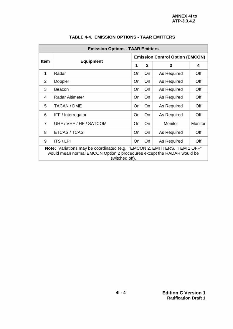
ANNEX 4I to ATP-3.3.4.2
4I - 4 Edition C Version 1 Ratification Draft 1
TABLE 4-4. EMISSION OPTIONS - TAAR EMITTERS
Emission Options - TAAR Emitters
Item Equipment Emission Control Option (EMCON)
1 2 3 4
1 Radar On On As Required Off
2 Doppler On On As Required Off
3 Beacon On On As Required Off
4 Radar Altimeter On On As Required Off
5 TACAN / DME On On As Required Off
6 IFF / Interrogator On On As Required Off
7 UHF / VHF / HF / SATCOM On On Monitor Monitor
8 ETCAS / TCAS On On As Required Off
9 ITS / LPI On On As Required Off Note: Variations may be coordinated (e.g., “EMCON 2, EMITTERS, ITEM 1 OFF”
would mean normal EMCON Option 2 procedures except the RADAR would be switched off).
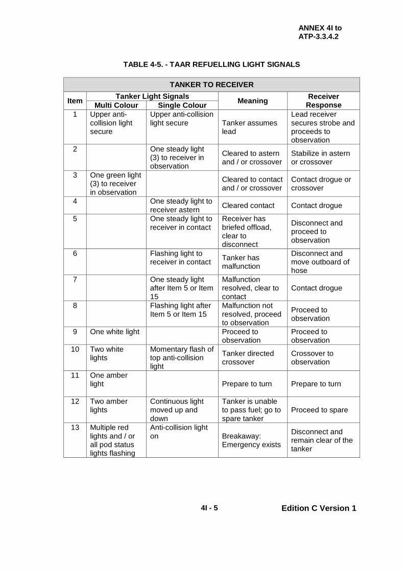
ANNEX 4I to ATP-3.3.4.2
4I - 5 Edition C Version 1
TABLE 4-5. - TAAR REFUELLING LIGHT SIGNALS
TANKER TO RECEIVER
Item Tanker Light Signals Meaning Receiver Response Multi Colour Single Colour
1 Upper anti-collision light secure
Upper anti-collision light secure Tanker assumes
lead
Lead receiver secures strobe and proceeds to observation
2 One steady light (3) to receiver in observation
Cleared to astern and / or crossover
Stabilize in astern or crossover
3 One green light (3) to receiver in observation
Cleared to contact and / or crossover
Contact drogue or crossover
4 One steady light to receiver astern Cleared contact Contact drogue
5 One steady light to receiver in contact
Receiver has briefed offload, clear to disconnect
Disconnect and proceed to observation
6 Flashing light to receiver in contact Tanker has
malfunction
Disconnect and move outboard of hose
7 One steady light after Item 5 or Item 15
Malfunction resolved, clear to contact
Contact drogue
8 Flashing light after Item 5 or Item 15
Malfunction not resolved, proceed to observation
Proceed to observation
9 One white light Proceed to observation
Proceed to observation
10 Two white lights
Momentary flash of top anti-collision light
Tanker directed crossover
Crossover to observation
11 One amber light
Prepare to turn Prepare to turn
12 Two amber lights
Continuous light moved up and down
Tanker is unable to pass fuel; go to spare tanker
Proceed to spare
13 Multiple red lights and / or all pod status lights flashing
Anti-collision light on Breakaway:
Emergency exists
Disconnect and remain clear of the tanker

ANNEX 4I to ATP-3.3.4.2
4I - 6 Edition C Version 1
TABLE 4-6. TAAR REFUELLING LIGHT SIGNALS CONTINUED
PRIMARY TANKER TO SPARE TANKER
Item Tanker Light Signals Meaning Receiver Response Multi Colour Single Colour
14 Tanker flashes one white light (4)
Fuel flowing Spare may retract hoses
15 Tanker flashes two white lights (4)
Unable to refuel Spare tanker is primary
RECEIVER TO TANKER Item Tanker Light Signals Meaning Tanker Response 16 Receiver disconnects, manoeuvres
outboard of hose, and emits one steady light
Reset reel response
Reset hose
17 Receiver remains in contact or emits flashing light after Item 4
More fuel is required
Tanker provides additional offload as briefed
18 Flashes formation / position lights for 5 seconds
Receiver preparing to disconnect
19 Extended probe with the visible landing or search light ON (IR for NVG operations), IFF on EMERGENCY
An emergency fuel requirement exists; secure comms is to be used if available
Provide fuel as required
WARNING
WHEN PERFORMING TAAR SIMULTANEOUSLY WITH FIXED WING AAR, RECEIVERS ARE TO FLASH POSITION/FORMATION LIGHTS FOR 5 SEC PRIOR TO MOVEMENT TO DISCONNECT IN ORDER TO PRECLUDE SIMULTANEOUS DISCONNECTS AND POSSIBLE MIDAIR COLLISIONS. Notes: 1. A single flash is 2 sec in duration and given with either an Aldis lamp, flashlight,
signal light panel, search/landing light, etc. If, after a reasonable amount of time (situation dependent but perhaps 20-30 seconds), it is apparent that a signal has not been received, repeat the signal.
2. During EMCON 1 and 2, a visual signalling device is to be readily available for immediate use as a backup to any loss of communications.
3. Once the receiver or element has crossed over, an additional signal is required before leaving the observation position.
4. Tanker to Spare Tanker: Light signals are to be passed from scanner window/door (if able). In lieu of light signals, a radio call to indicate “FUEL FLOWING” or “UNABLE TO REFUEL” may be made.

ATP-3.3.4.2
5 - 1 Edition C Version 1
CHAPTER 5 NATIONAL AND ORGANISATIONAL PROCEDURES
TABLE OF CONTENT
Page No./Annex PRELIMINARIES Table of Content Page I 0501. Introduction Page I 0502. Format for National Data published in National SRD Page I 0503. Procedure for Making Changes to National SRD Page IV 0503. POC for Editor for ATP-3.3.4.2 Page V 5.1. INTRODUCTION The SRDs to Chapter 5 are provided by each nation or AAR organisation to assist AAR interoperability. The information provided gives tanker capabilities and characteristics relevant to AAR, and includes which receivers are cleared to refuel from its tankers. Each nation or organisation has its own instructions relating to AAR planning, AAR deployments and peacetime training constraints; the Annexes list the source document for this information. SRDs also list the national POCs, and any national or organisational reservations or amendments to the standard procedures of this ATP-56. SRD–AAR Clearances outlines the suggested procedure for obtaining AAR Clearances. SRD-AAR Tanker Capabilities summarizes the national tanker capabilities in tabular format. SRD- Tanker/Receiver Clearance Matrix will include a matrix of tanker/receiver clearances. 5.2. FORMAT FOR NATIONAL DATA PUBLISHED IN NATIONAL SRD (FORMER
CHAPTER 5 ANNEXES) The National SRDs are to be laid out in the following format. Nations with multiple tanker types may use sub-Annexes and Appendices.
a. Introduction.
b. Tanker Aircraft Type. All tanker types are listed and the following information is given for each type:
(1) AAR Equipment. Type of AAR equipment (boom or drogue) and
location of the equipment. This includes diagrams/photographs of hose and drogue markings and dimensions.
(2) Refuelling Heights and Speeds. Refuelling height and speed
envelope, of the tanker.
(3) Maximum Transferable Fuel.

ATP-3.3.4.2
5 - 2 Edition C Version 1
(4) Fuel transfer rate.
(5) Regulated Fuel Pressure.
(6) Fuel Types Available for AAR:
(a) Primary/usual type of fuel.
(b) Alternate types of fuel that may be carried on occasion.
(7) Receiver Clearances.
(a) Receiver Aircraft Permanently Certified. These clearances are based on the mechanical compatibility between the tanker and receiver aircraft. The receivers in this sub para should not be subject to any mechanical restrictions. Those receivers with restrictions should be listed under subsequent sub paras.
(b) Receiver Aircraft Certified for Approved
Operations/Exercises. This section lists those receivers where the clearance is limited to contingency operations and certain approved exercises. In these cases, national approval from both tanker and receiver nation may be required.
(8) Lighting. This section should detail the AAR equipment signal
lights, night floodlighting and electroluminescent markings.
(9) Mark facilities.
(10) Dimensions. This section should include a drawing with the physical dimension of the tanker aircraft, together with the location of the AAR store.
(11) RV aids.
c. Receiver Qualification and Currency. This section should cover
receiver qualification, currency requirements.
d. Source Documents
e. POC for National SRD. The office responsible for the content of the National SRD. Each nation or organisation is responsible for reviewing/updating their SRD regularly and informing the Editor of any changes. Ideally, this review/ update should be conducted at least annually to maintain the currency and credibility of the National Annex.

ATP-3.3.4.2
5 - 3 Edition C Version 1
f. POC for Tanker/Receiver Clearances. The initial point of contact for all matters concerning tanker and receiver clearances. If available, details of the normal clearance process, including any standard questionnaire.
g. POC for STANEVAL. The initial point of contact for all international AAR
and STANEVAL matters.
NOTE
POC INFORMATION TO INCLUDE JOB TITLE, FULL POSTAL ADDRESS, TELEPHONE NUMBER, FAX NUMBER, AND EMAIL ADDRESS. AN OFFICE EMAIL ADDRESS IS PREFERRED.
h. National SRD Last Updated. Date of last change.
i. National Reservations. Any national reservations or amendments to
the standard ATP-56 procedures. 5.3. PROCEDURE FOR MAKING CHANGES TO NATIONAL SRD
a. National data published in the National SRD contain only factual information..
b. Change requests will be included as near as possible to the following
due dates: 1st February and 1st August. Inputs for change should be sent to the Custodian by either email or via the NSA AAR Panel Forum (http://nsa.nato.int/), at least 4 weeks prior to the above release dates. However, changes of an urgent nature will be included immediately on request from national SRD POC. Notification of urgent changes will be by email to the National POC and via the NSA AAR Panel Forum
c. All amendments to the SRD will be electronic and posted on: http://www.raf.mod.uk/downloads/airtoair56b.cfm and https://nsa.nato.int/protected/.
d. Users of the National SRD are strongly advised to refer to the web copy
to ensure that they have the latest amendment to the relevant SRD. If in doubt, contact the SRD POC.
5.4. POC FOR EDITOR OF ATP-3.3.4.2 NATO AAR Coordination Cell Combat Support Branch Joint Air Power Competence Centre (JAPCC) Von-Seydlitz-Kaserne
Römerstraße 140 D-47546 Kalkar Germany Tel: (+49) 2824 90 2294/2212/2215 Fax: (+49) 2824 90 2274

ATP-3.3.4.2
5 - 4 Edition C Version 1
CRONOS: JAPCC CS AAR Email: [email protected]
NSA AAR Panel Forum (http://nsa.nato.int/)

ATP-3.3.4.2 (C)(1)


![VT 5 - oepm.es · vaccine against tick infection WO 2012006149 A2 20120112 ... (4-nitro-phenyl)-benz-oxsazol-5-yl]-propan- ... Pure Chinese medicine](https://img.pdfslide.us/doc/110x75/5ac853477f8b9a5d718c8cf5/vt-5-oepmes-against-tick-infection-wo-2012006149-a2-20120112-4-nitro-phenyl-benz-oxsazol-5-yl-propan-.jpg)