Embed Size (px)
DESCRIPTION
Diafragmas
Citation preview
Diaphragm Considerations for
Structural EngineersStructural Engineers
By Allen Adams, P.E., S.E.
Bentley Systems, Inc.
SE University, November, 2011 www.LearnWithSEU.com
2
3
4
5
6
Types of Diaphragms
� Rigid
7
Rigid Diaphragm
� Infinitely Rigid in the plane of the floor.
� Computationally Efficient.
� Frames are rigidly connected.� Frames are rigidly connected.
8
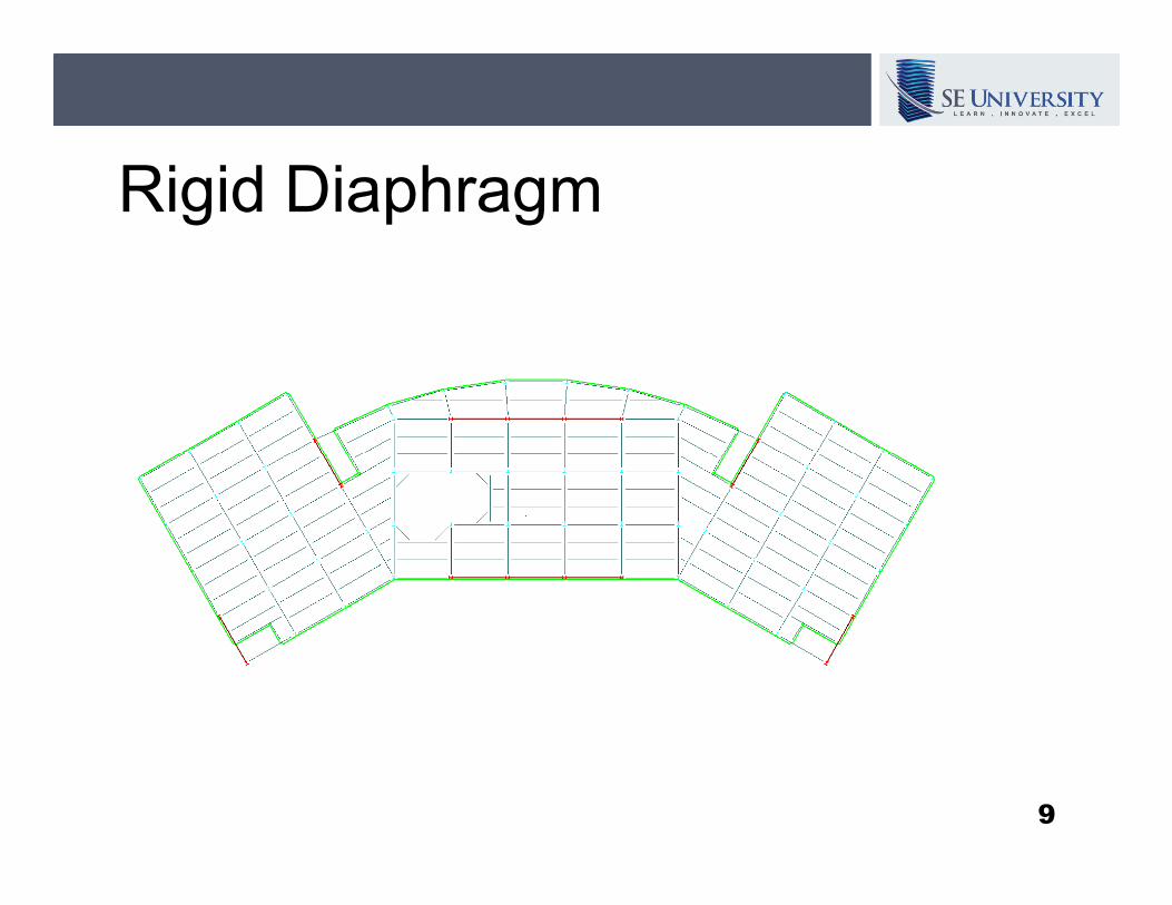
Rigid Diaphragm
9
Types of Diaphragms
� Rigid
� Flexible
12
Flexible Diaphragm
� No diaphragm stiffness.
� No interaction between frames.
13
Types of Diaphragms
� Rigid
� Flexible
� Semi-rigid� Semi-rigid
14
Semi-rigid Diaphragm
� Some diaphragm stiffness.
� Interaction between frames.
15
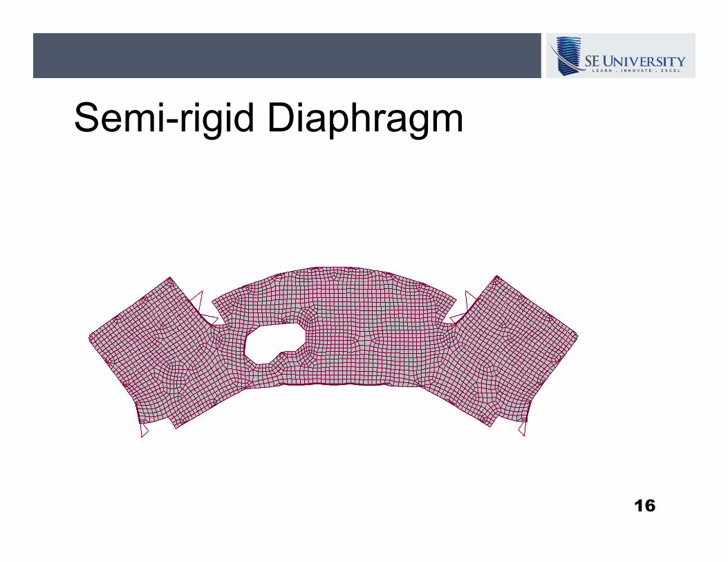
Semi-rigid Diaphragm
16
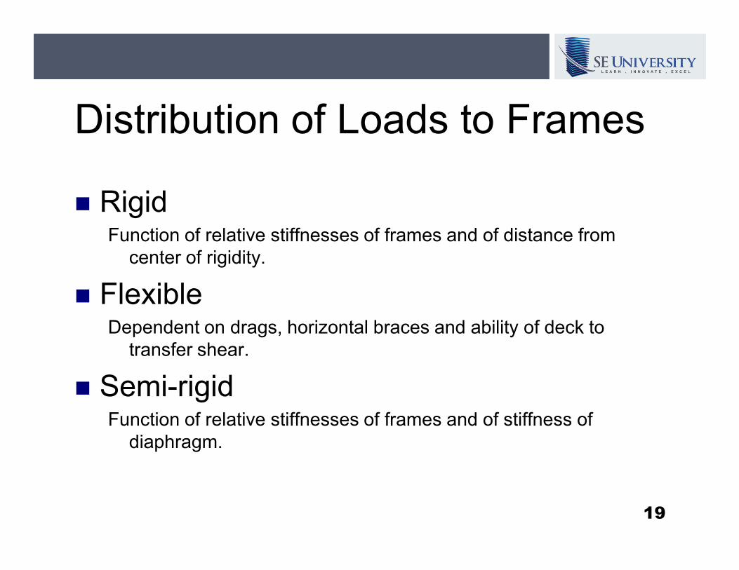
Distribution of Loads to Frames
� RigidFunction of relative stiffnesses of frames and of distance from
center of rigidity.
� Flexible� FlexibleDependent on drags, horizontal braces and ability of deck to
transfer shear.
� Semi-rigidFunction of relative stiffnesses of frames and of stiffness of
diaphragm.
19
Code Requirements
� ASCE 7-10 Minimum Design Loads for
Buildings and Other Structures
� International Building Code 2009� International Building Code 2009
20
12.3.1 Diaphragm Flexibility
The structural analysis shall consider the relative stiffnesses of diaphragms and the vertical elements of the seismic force-resisting system. Unless a diaphragm can be idealized as system. Unless a diaphragm can be idealized as either flexible or rigid in accordance with Sections 12.3.1.1, 12.3.1.2, or 12.3.1.3, the structural analysis shall explicitly include consideration of the stiffness of the diaphragm (i.e., semirigid modeling assumption).
21
12.3.1.1 Flexible Diaphragm
Condition
Untopped steel decking or wood structural
panels:
a. Steel or concrete braced frames or concrete, a. Steel or concrete braced frames or concrete,
masonry, or steel shear walls.
b. One- and two-family dwellings
c. Light-frame construction (see code for
conditions, note that ASCE 7 is modified by
IBC 2009 Section 1613.6.1).
22
12.3.1.2 Rigid Diaphragm
Condition
Diaphragms of concrete slab or concrete
filled metal deck with span-to-depth ratios
of 3 or less in structures that have no of 3 or less in structures that have no
horizontal irregularities are permitted to be
idealized as rigid.
23
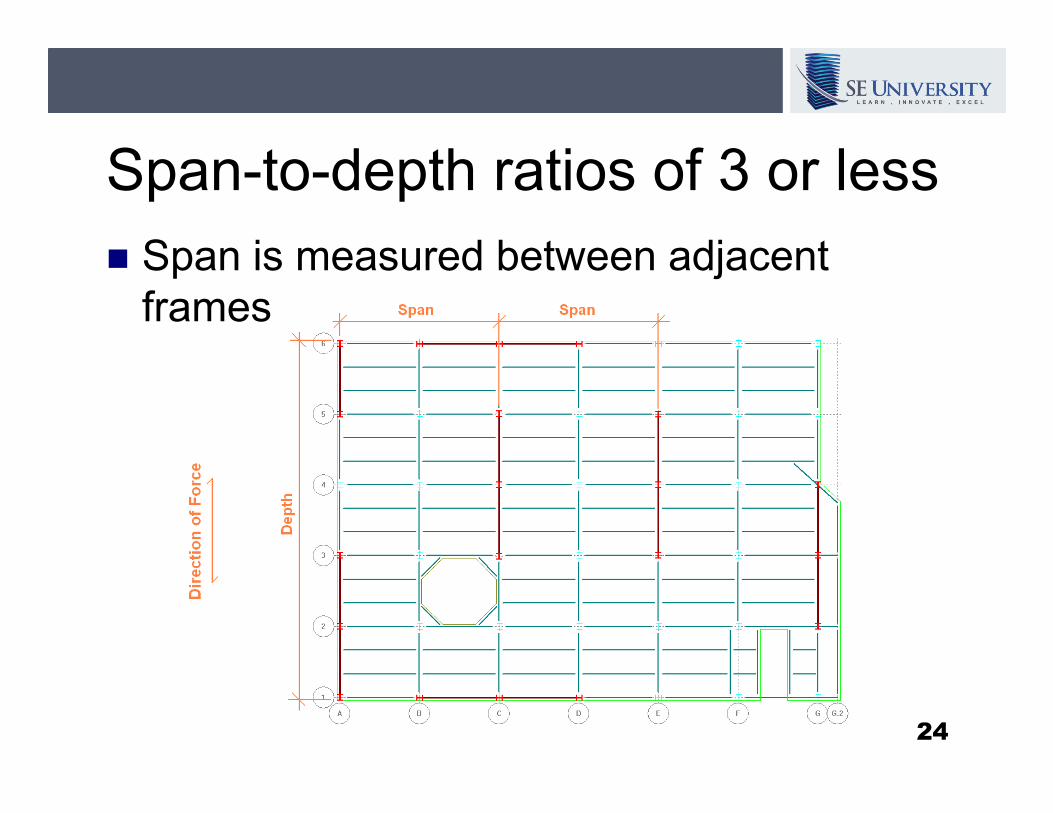
Span-to-depth ratios of 3 or less
� Span is measured between adjacent
frames.
24
12.3.2.1 Horizontal Irregularity
Structures having one or more of the
irregularity types listed in Table 12.3-1
shall be designated as having a horizontal
structural irregularity.structural irregularity.
1. Torsional Irregularity
2. Reentrant Corner
3. Diaphragm Discontinuity
4. Out-of-Plane Offset
5. Nonparallel System25
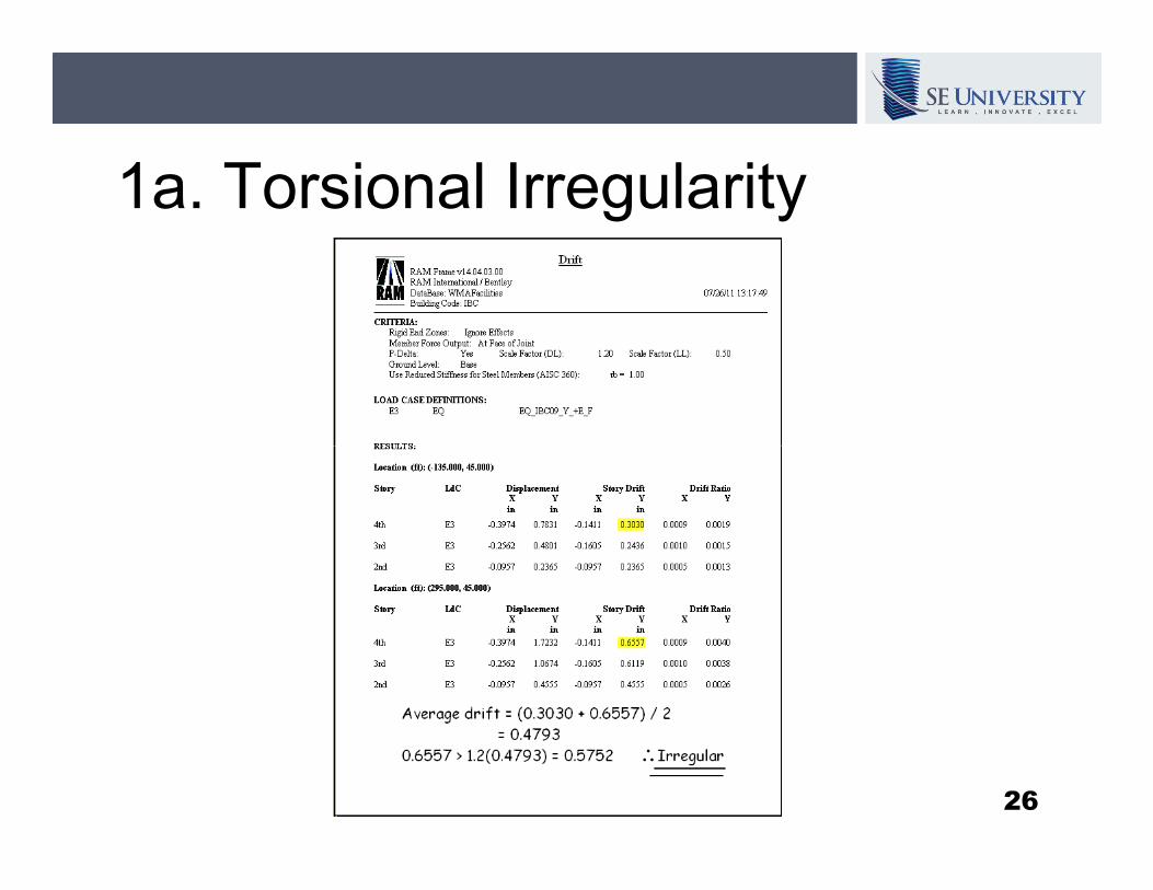
1a. Torsional Irregularity
26
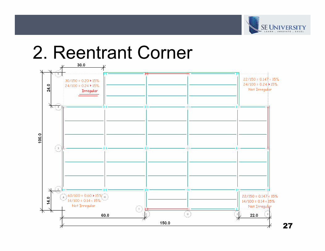
2. Reentrant Corner
27
3. Diaphragm Discontinuity
� Abrupt discontinuity or variation in
stiffness.
28
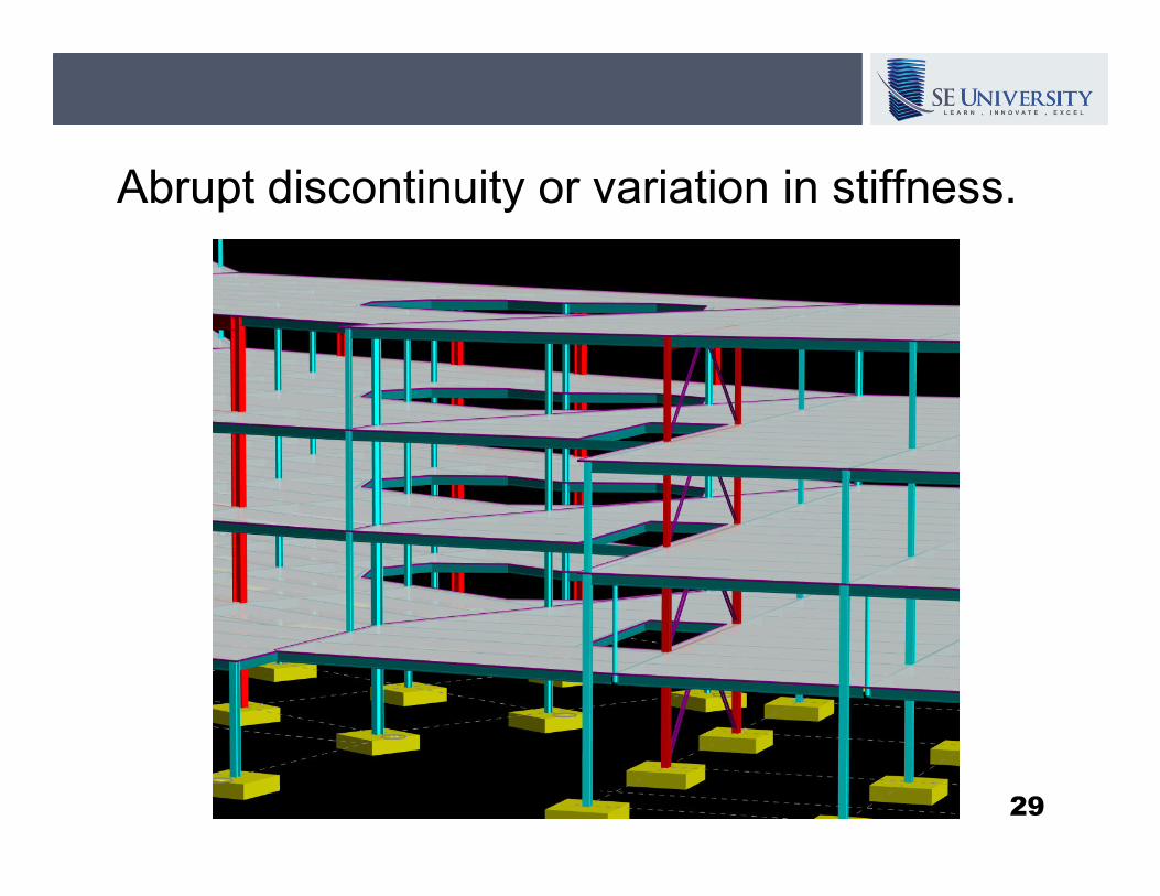
Abrupt discontinuity or variation in stiffness.
29
3. Diaphragm Discontinuity
� Abrupt discontinuity or variation in
stiffness.
� Cutout or open area greater than 50% of � Cutout or open area greater than 50% of
the gross enclosed diaphragm area.
30
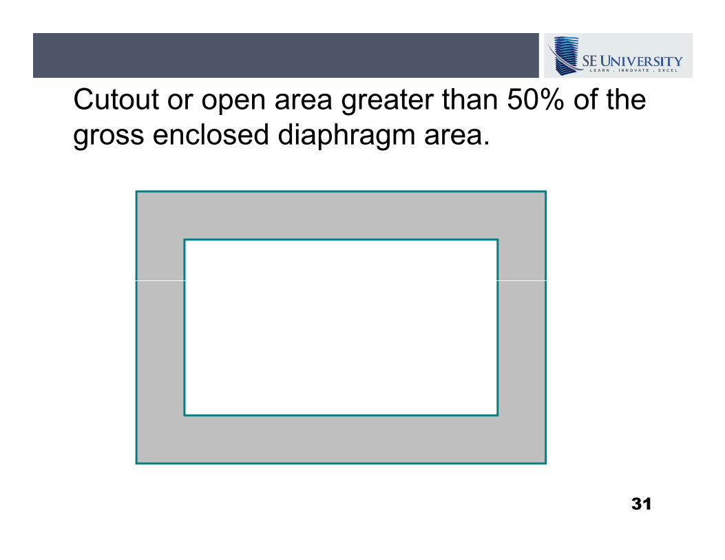
Cutout or open area greater than 50% of the
gross enclosed diaphragm area.
31
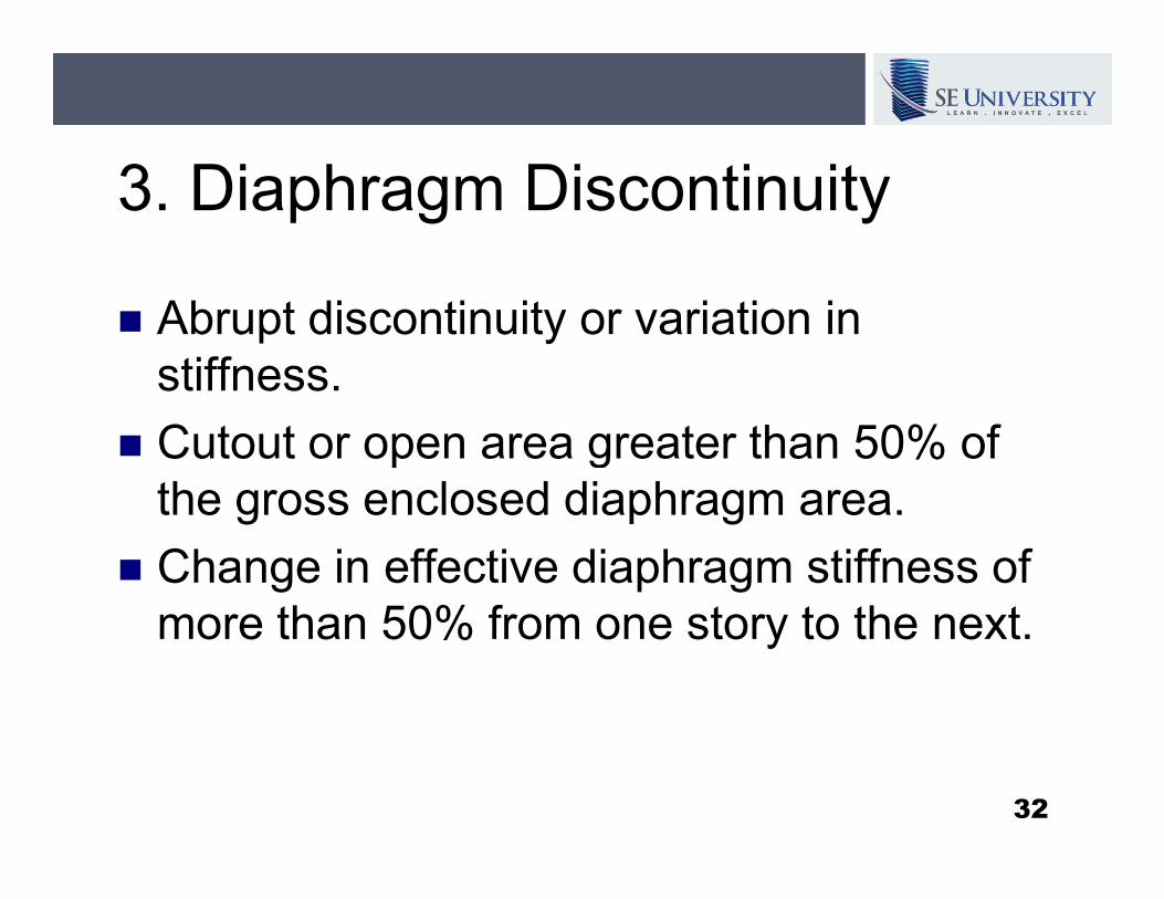
3. Diaphragm Discontinuity
� Abrupt discontinuity or variation in
stiffness.
� Cutout or open area greater than 50% of � Cutout or open area greater than 50% of
the gross enclosed diaphragm area.
� Change in effective diaphragm stiffness of
more than 50% from one story to the next.
32
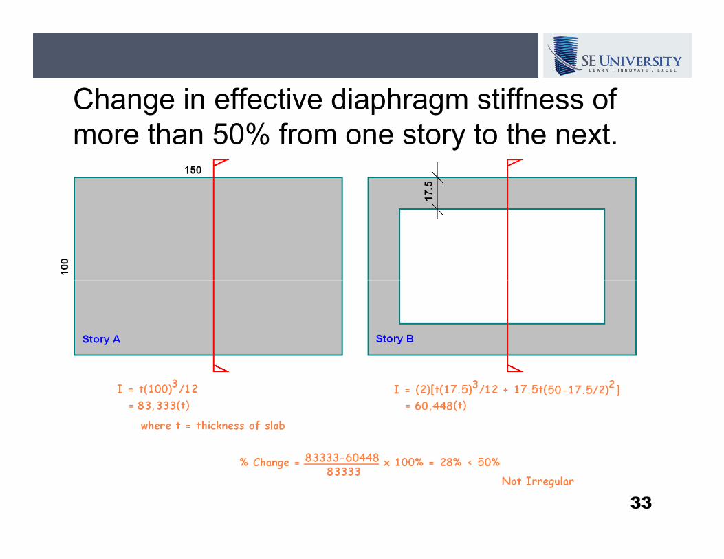
Change in effective diaphragm stiffness of
more than 50% from one story to the next.
33
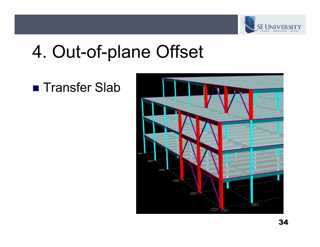
4. Out-of-plane Offset
� Transfer Slab
34
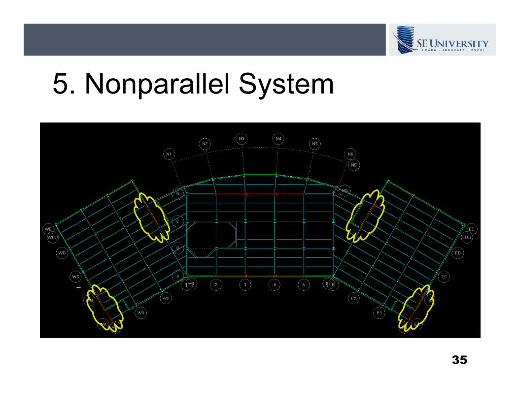
5. Nonparallel System
35

12.3.2.1 Horizontal Irregularity
Structures having one or more of the
irregularity types listed in Table 12.3-1
shall be designated as having a horizontal
structural irregularity.structural irregularity.
1. Torsional Irregularity
2. Reentrant Corner
3. Diaphragm Discontinuity
4. Out-of-Plane Offset
5. Nonparallel System36
12.3.1.2 Rigid Diaphragm
Condition
Diaphragms of concrete slab or concrete
filled metal deck with span-to-depth ratios
of 3 or less in structures that have no of 3 or less in structures that have no
horizontal irregularities are permitted to be
idealized as rigid.
37
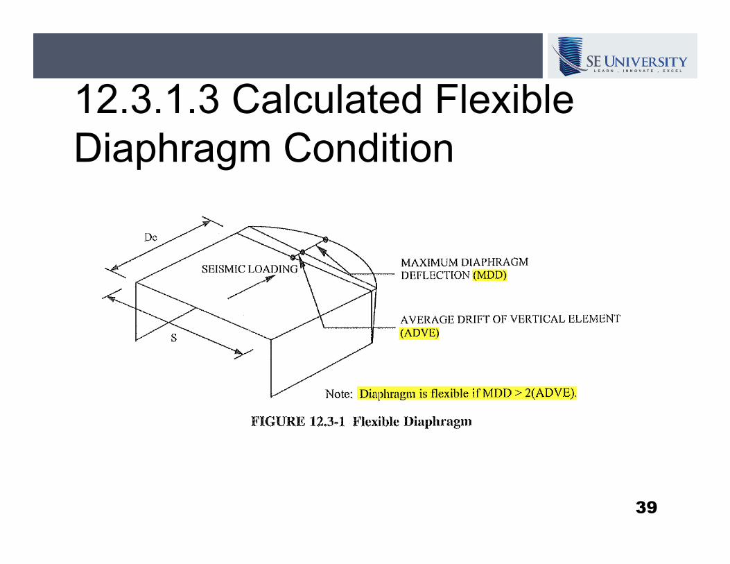
12.3.1.3 Calculated Flexible
Diaphragm Condition
Diaphragms not satisfying the condition of
Sections 12.3.1.1 [flexible] or 12.3.1.2
[rigid] are permitted to be idealized as [rigid] are permitted to be idealized as
flexible where the … in-plane deflection of
the diaphragm … is more than two times
the average story drift of adjoining vertical
elements of the seismic force-resisting
system….
38
12.3.1.3 Calculated Flexible
Diaphragm Condition
39

12.3.1 Diaphragm Flexibility
The structural analysis shall consider the relative stiffnesses of diaphragms and the vertical elements of the seismic force-resisting system. Unless a diaphragm can be idealized as system. Unless a diaphragm can be idealized as either flexible or rigid in accordance with Sections 12.3.1.1, 12.3.1.2, or 12.3.1.3, the structural analysis shall explicitly include consideration of the stiffness of the diaphragm (i.e., semirigid modeling assumption).
40
12.7.3 Structural Modeling
A mathematical model of the structure shall
be constructed for the purpose of
determining member forces and structure determining member forces and structure
displacements…. Where the diaphragms
have not been classified as rigid or flexible
in accordance with Section 12.3.1, the
model shall include representation of the
diaphragm’s stiffness characteristics….
41
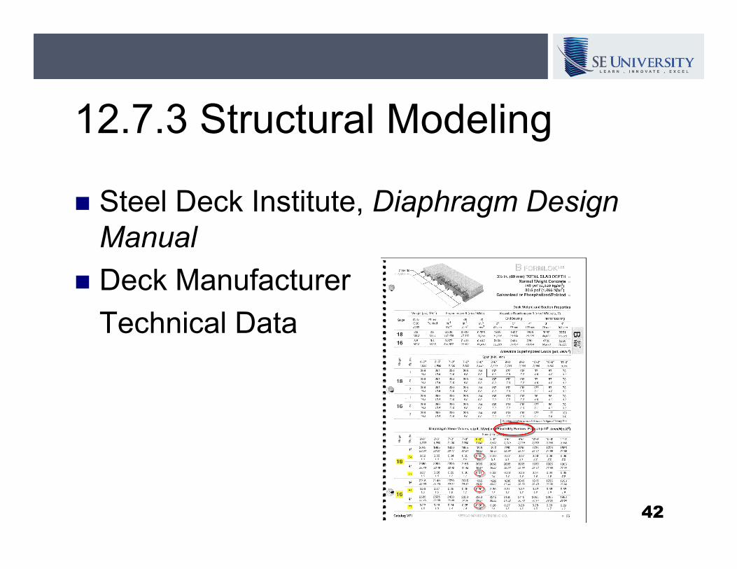
12.7.3 Structural Modeling
� Steel Deck Institute, Diaphragm Design
Manual
� Deck Manufacturer� Deck Manufacturer
Technical Data
42
Diaphragm Considerations for
Structural Engineers
Questions???
43
Wind and Seismic Loads on
Diaphragms
44
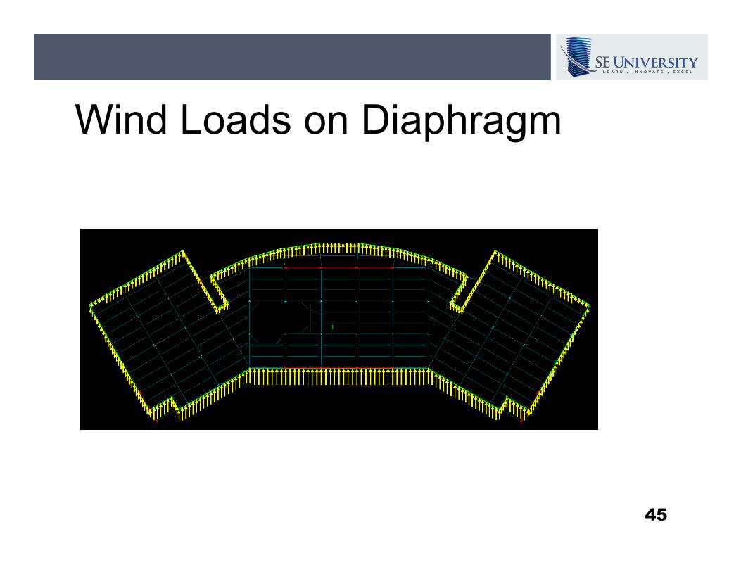
Wind Loads on Diaphragm
45
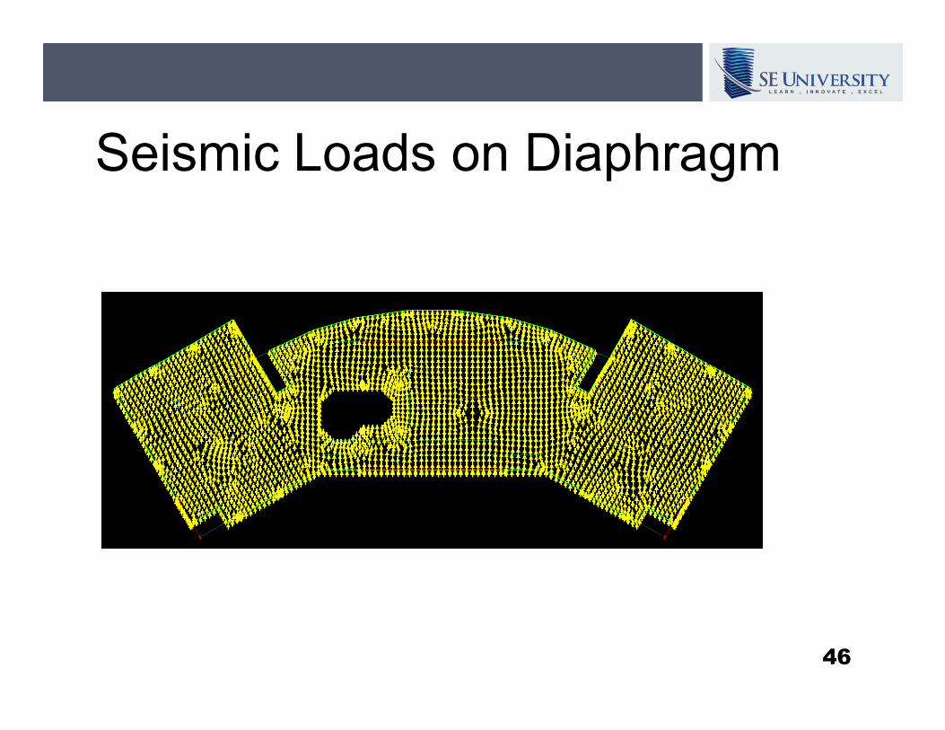
Seismic Loads on Diaphragm
46
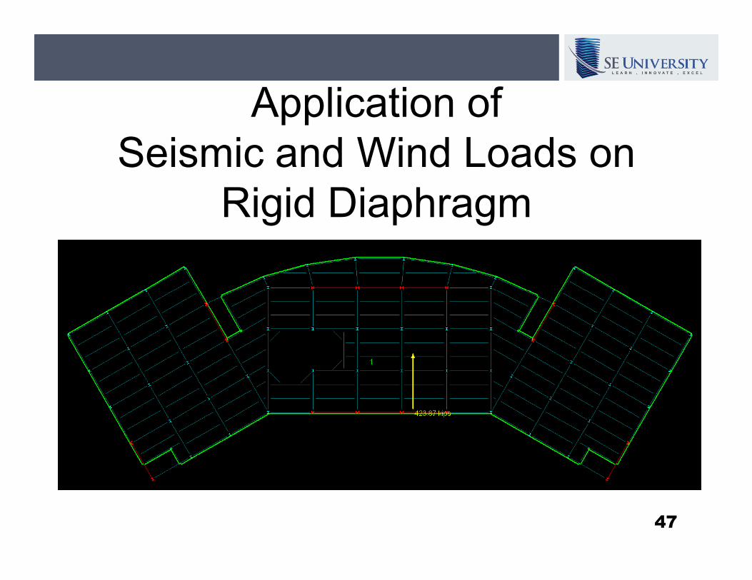
Application of
Seismic and Wind Loads on
Rigid Diaphragm
47
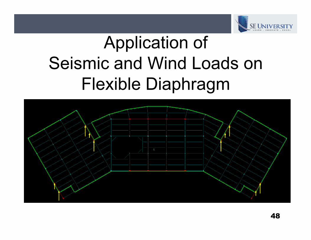
Application of
Seismic and Wind Loads on
Flexible Diaphragm
48
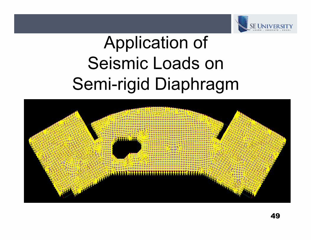
Application of
Seismic Loads on
Semi-rigid Diaphragm
49
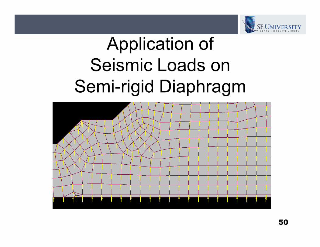
Application of
Seismic Loads on
Semi-rigid Diaphragm
50
12.8.4 Horizontal Distribution of
Forces
The seismic design story shear … shall be
distributed to the various vertical elements
of the seismic force-resisting system… of the seismic force-resisting system…
based on the relative lateral stiffness of
the vertical resisting elements and the
diaphragm.
51
12.8.4.1 Inherent Torsion
“For diaphragms that are not flexible, the
distribution of lateral forces at each level
shall consider the effect of the inherent
torsion moment, M , resulting from torsion moment, Mt, resulting from
eccentricity between the location of the
center of mass and the center of rigidity.”
Note: this is automatically accounted for in a
3D analysis.
52
12.8.4.1 Inherent Torsion
“For flexible diaphragms, the distribution of
forces to the vertical elements shall
account for the position and distribution of
the masses supported.”the masses supported.”
Note: this needs to be considered when
determining the nodal loads applied to the
frames.
53
12.8.4.2 Accidental Torsion
“Where diaphragms are not flexible, the
design shall include … the accidental
torsional moments caused by assumed
displacement of the center of mass each displacement of the center of mass each
way from its actual location by a distance
equal to 5% of the dimension of the
structure perpendicular to the direction of
the applied forces.”
54

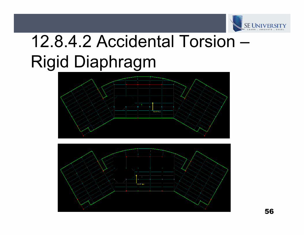
12.8.4.2 Accidental Torsion –
Rigid Diaphragm
55
12.8.4.2 Accidental Torsion –
Rigid Diaphragm
56
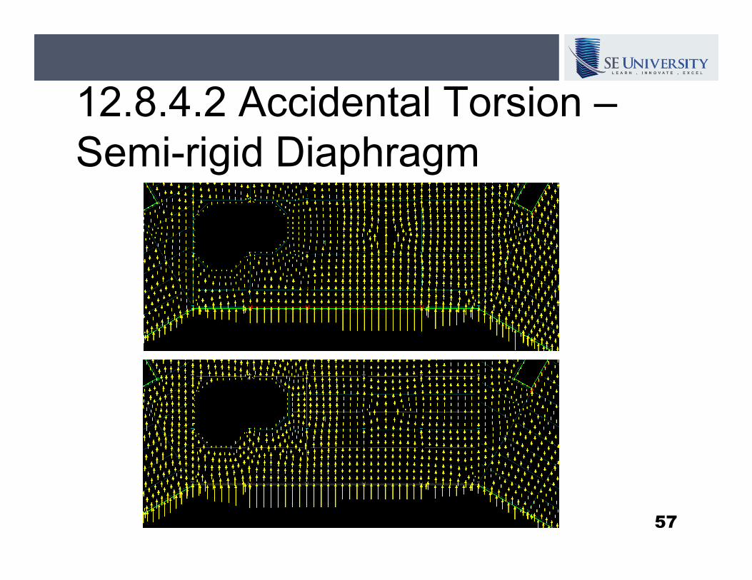
12.8.4.2 Accidental Torsion –
Semi-rigid Diaphragm
57
12.10 Diaphragms, Chords and
Collectors
“Diaphragms shall be designed for both the
shear and bending stresses resulting from
the design forces.”the design forces.”
58
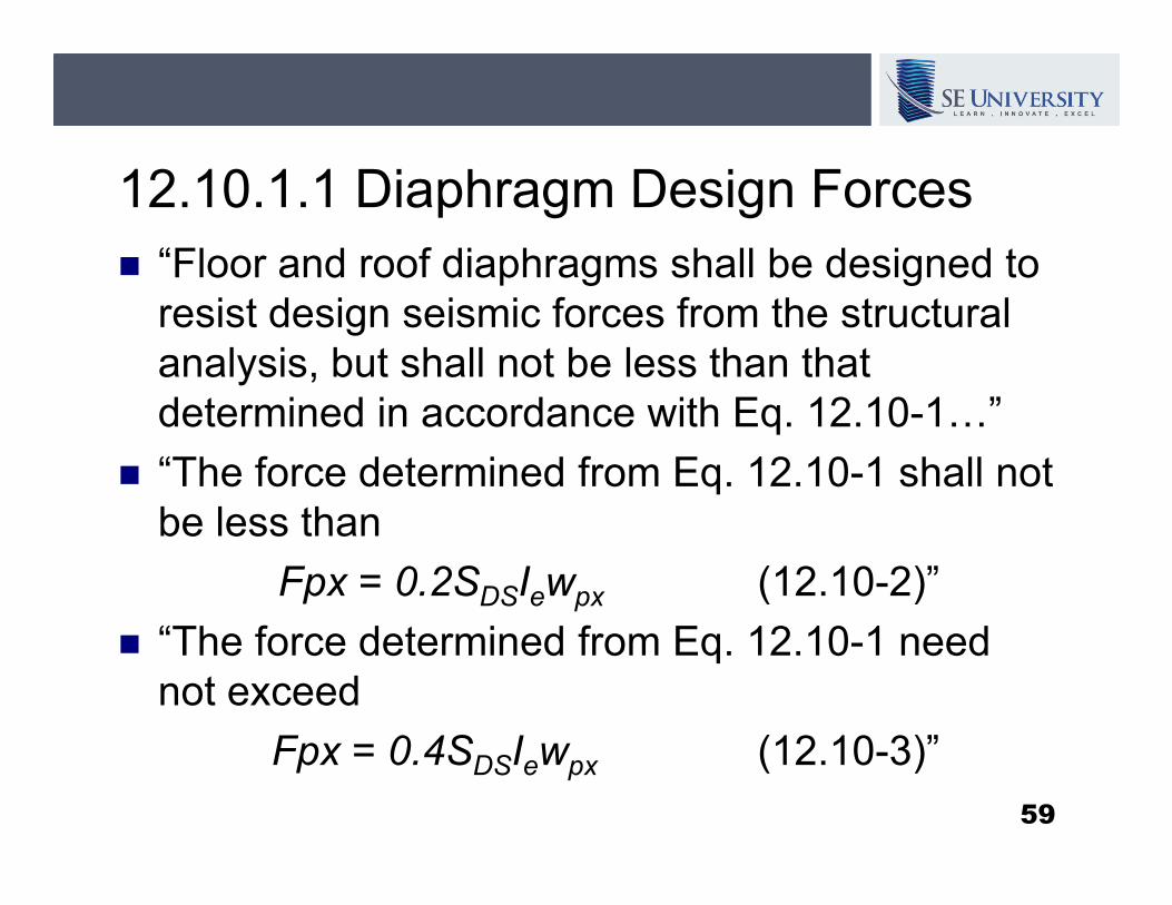
12.10.1.1 Diaphragm Design Forces
� “Floor and roof diaphragms shall be designed to
resist design seismic forces from the structural
analysis, but shall not be less than that
determined in accordance with Eq. 12.10-1…”
“The force determined from Eq. 12.10-1 shall not � “The force determined from Eq. 12.10-1 shall not
be less than
Fpx = 0.2SDSIewpx (12.10-2)”
� “The force determined from Eq. 12.10-1 need
not exceed
Fpx = 0.4SDSIewpx (12.10-3)”
59
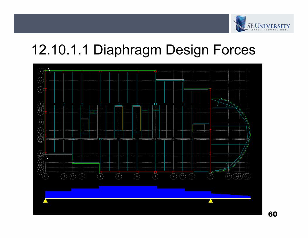
12.10.1.1 Diaphragm Design Forces
60
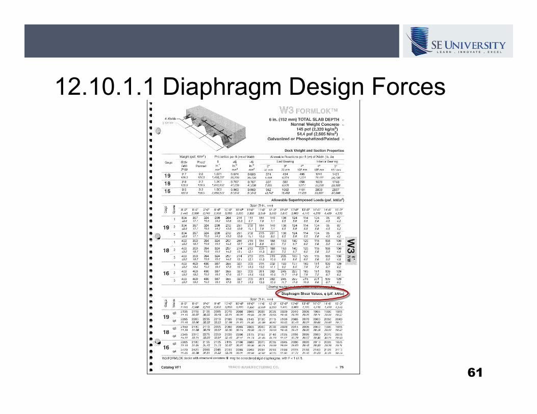
12.10.1.1 Diaphragm Design Forces
61
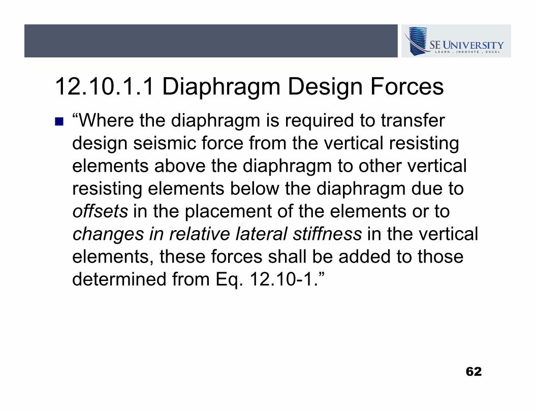
12.10.1.1 Diaphragm Design Forces
� “Where the diaphragm is required to transfer
design seismic force from the vertical resisting
elements above the diaphragm to other vertical
resisting elements below the diaphragm due to
offsets in the placement of the elements or to offsets in the placement of the elements or to
changes in relative lateral stiffness in the vertical
elements, these forces shall be added to those
determined from Eq. 12.10-1.”
62
12.10.1.1 Diaphragm Design Forces
“The redundancy factor, ρ, applies to the design of
diaphragms in structures assigned to Seismic
Design Categories D, E, or F.”
� “For inertial forces calculated in accordance with Eq. � “For inertial forces calculated in accordance with Eq.
12.10-1, the redundancy factor shall equal 1.0.”
� “For transfer forces the redundancy factor shall be the
same as that used for the structure [1.0 or 1.3].”
63
12.10.1.1 Diaphragm Design Forces
“For structures having horizontal or vertical
structural irregularities of the types indicated in
Section 12.3.3.4, the requirements of that
section shall also apply.”
� 12.3.3.4 Increase in Forces Due to Irregularities
for Seismic Design Categories D through F.25% increase in design forces for some elements in some
cases
64
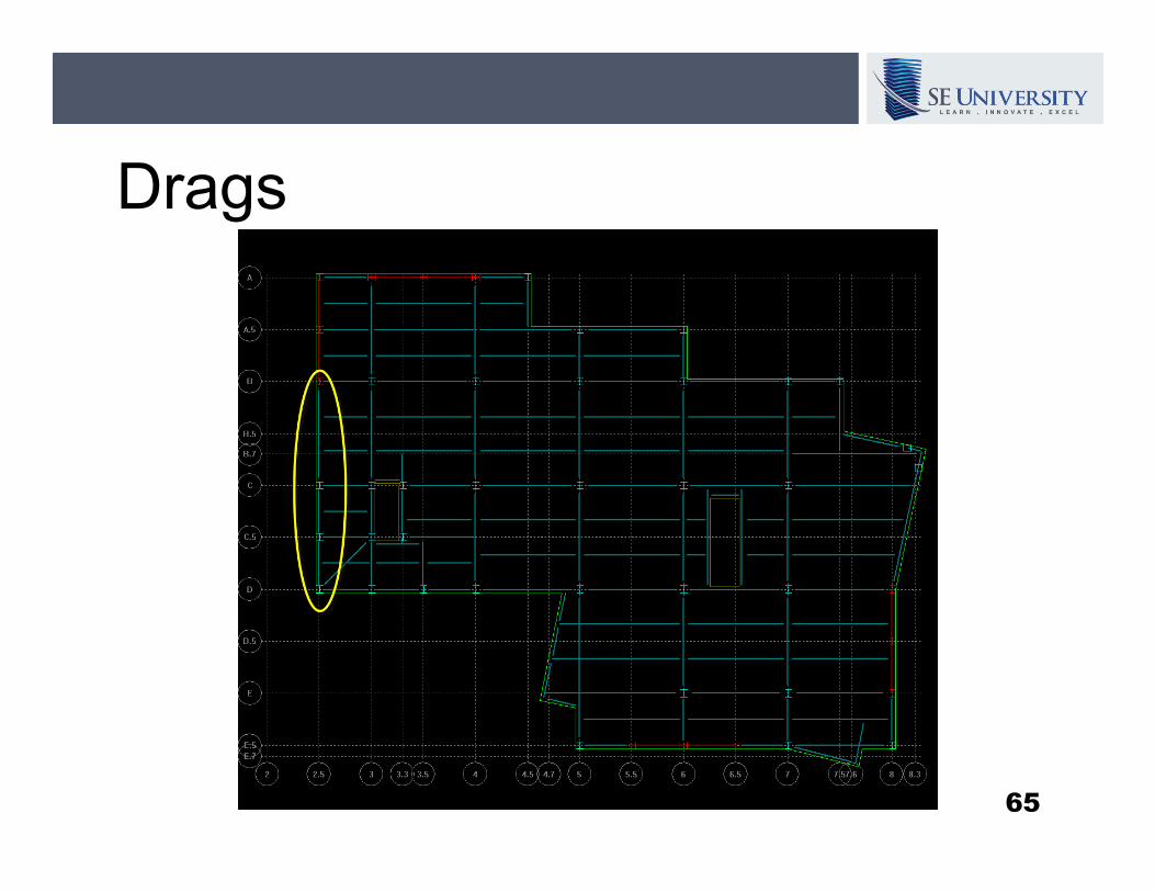
Drags
65
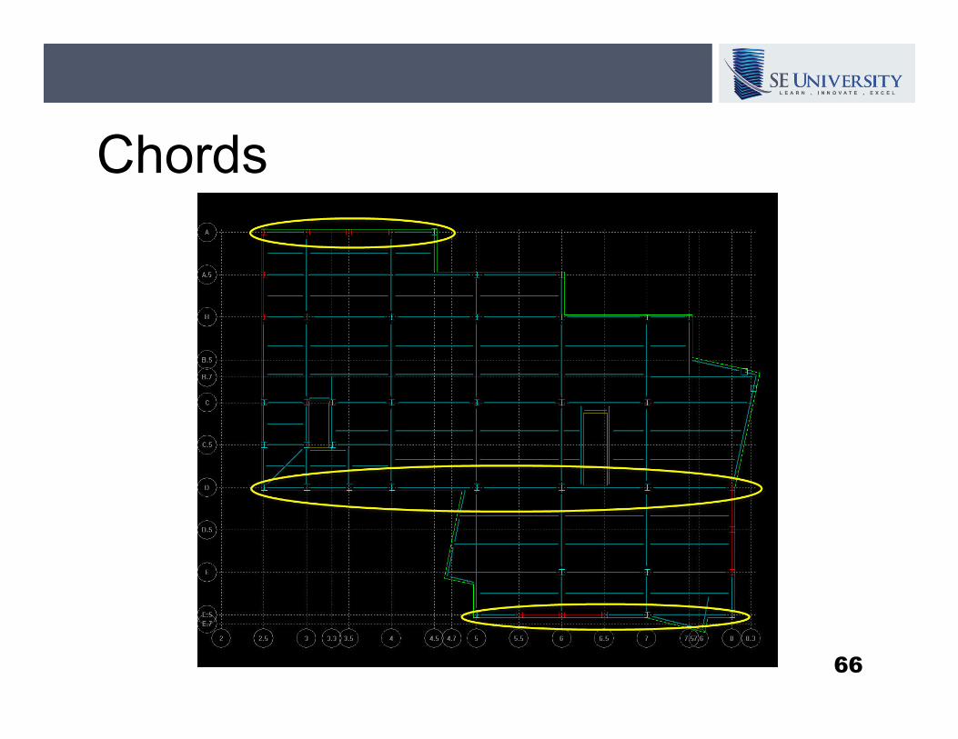
Chords
66
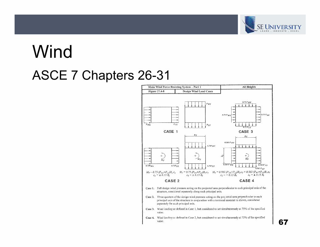
Wind
ASCE 7 Chapters 26-31
67
Diaphragm Considerations for
Structural EngineersStructural Engineers
By Allen Adams, P.E., S.E.
Bentley Systems, Inc.
SE University, November, 2011 www.LearnWithSEU.com