Embed Size (px)
Citation preview
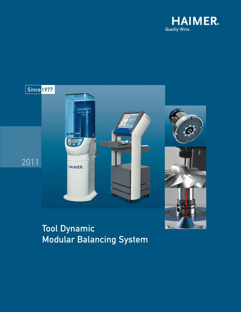
2011
Tool DynamicModular Balancing System
2 Haimer USA, LLC · 134 E. Hill Street · Villa Park, IL 60181 USA · Phone (630)833-1500 · Fax (630)833-1507 · [email protected] · www.haimer-usa.com
C o n T e n T
HAIMER Tool Dynamic Balancing Technology Page Why should I buy a Balancing Machine? 4 Case Studies 6
Modular Balancing System TD 1002 8 TD 2009 Economic 10 TD 2009 Economic Plus 12 TD 2009 Comfort 14 TD 2009 Comfort Plus 16
Optional Configurations 18
Control Terminal and Tool Dynamic TD Software 4.0
Tool Dynamic Control Terminal 22 Tool Dynamic TD Software 4.0 23
Tool Balancing and Presetting TD Preset 24
Special Balancing Machines TD 800 26
Automatic Balancing Technology TD 2010 Automatic 28
Application Examples 32
Accessories 35
3Haimer USA, LLC · 134 E. Hill Street · Villa Park, IL 60181 USA · Phone (630)833-1500 · Fax (630)833-1507 · [email protected] · www.haimer-usa.com
5.
!
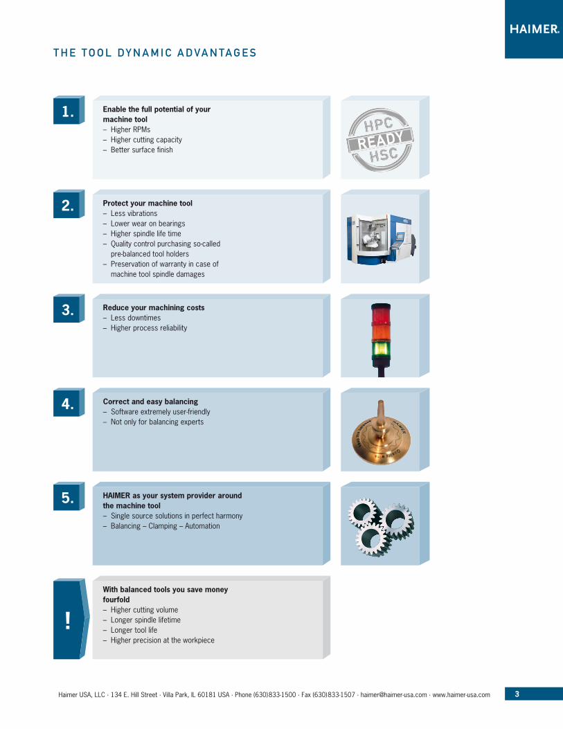
4. Correct and easy balancing – Software extremely user-friendly – Not only for balancing experts
HAIMER as your system provider around the machine tool – Single source solutions in perfect harmony – Balancing – Clamping – Automation
With balanced tools you save money fourfold – Higher cutting volume – Longer spindle lifetime – Longer tool life – Higher precision at the workpiece
3. Reduce your machining costs – Less downtimes – Higher process reliability
2. Protect your machine tool – Less vibrations – Lower wear on bearings – Higher spindle life time – Quality control purchasing so-called pre-balanced tool holders
– Preservation of warranty in case of machine tool spindle damages
T h e T o o l D y n a M i C a D Va n Ta G e S
1. Enable the full potential of your machine tool – Higher RPMs – Higher cutting capacity – Better surface finish
4 Haimer USA, LLC · 134 E. Hill Street · Villa Park, IL 60181 USA · Phone (630)833-1500 · Fax (630)833-1507 · [email protected] · www.haimer-usa.com
W h y S h o u l D i B u y a B a l a n C i n G M a C h i n e ?
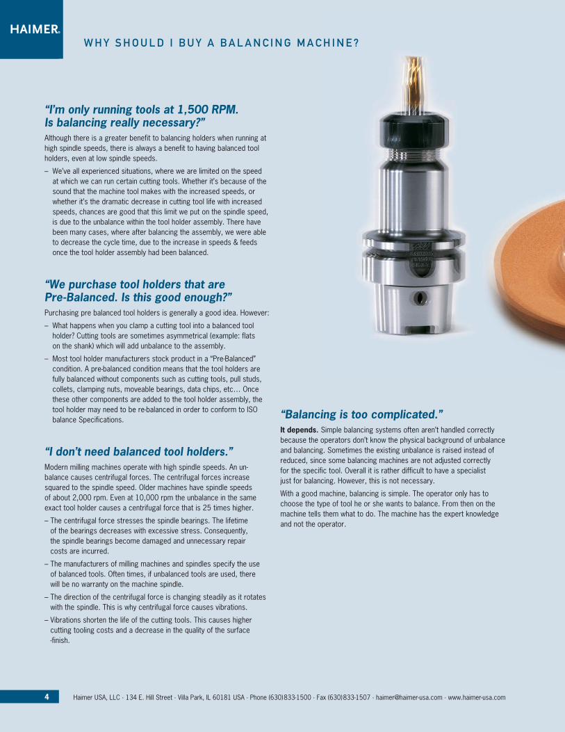
“I’m only running tools at 1,500 RPM. Is balancing really necessary?”Although there is a greater benefit to balancing holders when running at high spindle speeds, there is always a benefit to having balanced tool holders, even at low spindle speeds.
– We’ve all experienced situations, where we are limited on the speed at which we can run certain cutting tools. Whether it’s because of the sound that the machine tool makes with the increased speeds, or whether it’s the dramatic decrease in cutting tool life with increased speeds, chances are good that this limit we put on the spindle speed, is due to the unbalance within the tool holder assembly. There have been many cases, where after balancing the assembly, we were able to decrease the cycle time, due to the increase in speeds & feeds once the tool holder assembly had been balanced.
“We purchase tool holders that are Pre-Balanced. Is this good enough?” Purchasing pre balanced tool holders is generally a good idea. However:
– What happens when you clamp a cutting tool into a balanced tool holder? Cutting tools are sometimes asymmetrical (example: flats on the shank) which will add unbalance to the assembly.
– Most tool holder manufacturers stock product in a “Pre-Balanced” condition. A pre-balanced condition means that the tool holders are fully balanced without components such as cutting tools, pull studs, collets, clamping nuts, moveable bearings, data chips, etc… Once these other components are added to the tool holder assembly, the tool holder may need to be re-balanced in order to conform to ISO balance Specifications.
“I don’t need balanced tool holders.”Modern milling machines operate with high spindle speeds. An un-balance causes centrifugal forces. The centrifugal forces increase squared to the spindle speed. Older machines have spindle speeds of about 2,000 rpm. Even at 10,000 rpm the unbalance in the same exact tool holder causes a centrifugal force that is 25 times higher.
– The centrifugal force stresses the spindle bearings. The lifetime of the bearings decreases with excessive stress. Consequently, the spindle bearings become damaged and unnecessary repair costs are incurred.
– The manufacturers of milling machines and spindles specify the use of balanced tools. Often times, if unbalanced tools are used, there will be no warranty on the machine spindle.
– The direction of the centrifugal force is changing steadily as it rotates with the spindle. This is why centrifugal force causes vibrations.
– Vibrations shorten the life of the cutting tools. This causes higher cutting tooling costs and a decrease in the quality of the surface -finish.
“Balancing is too complicated.”It depends. Simple balancing systems often aren’t handled correctly because the operators don’t know the physical background of unbalance and balancing. Sometimes the existing unbalance is raised instead of reduced, since some balancing machines are not adjusted correctly for the specific tool. Overall it is rather difficult to have a specialist just for balancing. However, this is not necessary.
With a good machine, balancing is simple. The operator only has to choose the type of tool he or she wants to balance. From then on the machine tells them what to do. The machine has the expert knowledge and not the operator.
5Haimer USA, LLC · 134 E. Hill Street · Villa Park, IL 60181 USA · Phone (630)833-1500 · Fax (630)833-1507 · [email protected] · www.haimer-usa.com
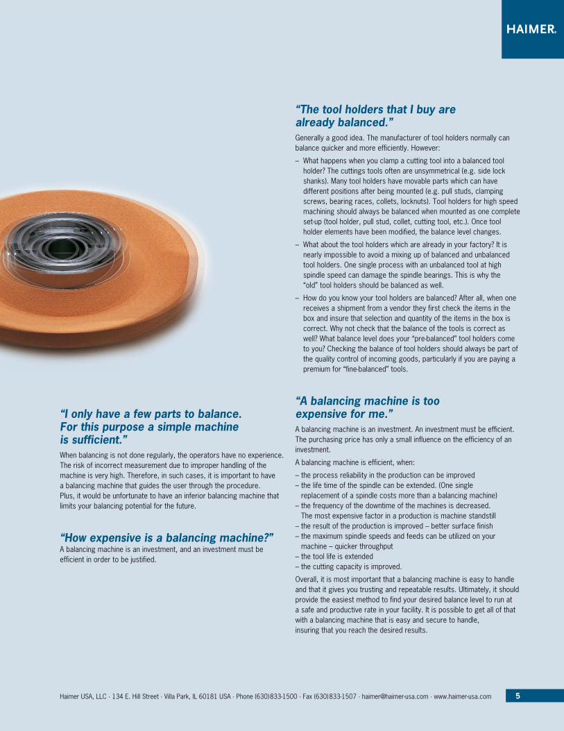
“I only have a few parts to balance. For this purpose a simple machine is sufficient.”When balancing is not done regularly, the operators have no experience. The risk of incorrect measurement due to improper handling of the machine is very high. Therefore, in such cases, it is important to have a balancing machine that guides the user through the procedure. Plus, it would be unfortunate to have an inferior balancing machine that limits your balancing potential for the future.
“How expensive is a balancing machine?”A balancing machine is an investment, and an investment must be efficient in order to be justified.
“The tool holders that I buy are already balanced.”Generally a good idea. The manufacturer of tool holders normally can balance quicker and more efficiently. However:
– What happens when you clamp a cutting tool into a balanced tool holder? The cuttings tools often are unsymmetrical (e.g. side lock shanks). Many tool holders have movable parts which can have different positions after being mounted (e.g. pull studs, clamping screws, bearing races, collets, locknuts). Tool holders for high speed machining should always be balanced when mounted as one complete set-up (tool holder, pull stud, collet, cutting tool, etc.). Once tool holder elements have been modified, the balance level changes.
– What about the tool holders which are already in your factory? It is nearly impossible to avoid a mixing up of balanced and unbalanced tool holders. One single process with an unbalanced tool at high spindle speed can damage the spindle bearings. This is why the “old” tool holders should be balanced as well.
– How do you know your tool holders are balanced? After all, when one receives a shipment from a vendor they first check the items in the box and insure that selection and quantity of the items in the box is correct. Why not check that the balance of the tools is correct as well? What balance level does your “pre-balanced” tool holders come to you? Checking the balance of tool holders should always be part of the quality control of incoming goods, particularly if you are paying a premium for “fine-balanced” tools.
“A balancing machine is too expensive for me.”A balancing machine is an investment. An investment must be efficient. The purchasing price has only a small influence on the efficiency of an investment.
A balancing machine is efficient, when:
– the process reliability in the production can be improved– the life time of the spindle can be extended. (One single
replacement of a spindle costs more than a balancing machine) – the frequency of the downtime of the machines is decreased.
The most expensive factor in a production is machine standstill – the result of the production is improved – better surface finish– the maximum spindle speeds and feeds can be utilized on your
machine – quicker throughput– the tool life is extended– the cutting capacity is improved.
Overall, it is most important that a balancing machine is easy to handle and that it gives you trusting and repeatable results. Ultimately, it should provide the easiest method to find your desired balance level to run at a safe and productive rate in your facility. It is possible to get all of that with a balancing machine that is easy and secure to handle, insuring that you reach the desired results.
6 Haimer USA, LLC · 134 E. Hill Street · Villa Park, IL 60181 USA · Phone (630)833-1500 · Fax (630)833-1507 · [email protected] · www.haimer-usa.com
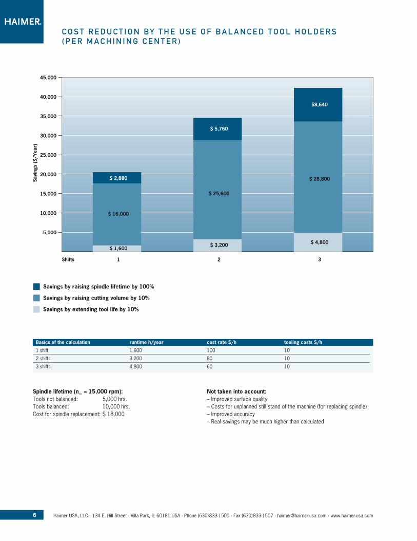
C o S T r e D u C T i o n B y T h e u S e o f B a l a n C e D T o o l h o l D e r S ( p e r M a C h i n i n G C e n T e r )
Spindle lifetime (nmax = 15,000 rpm): Tools not balanced: 5,000 hrs. Tools balanced: 10,000 hrs. Cost for spindle replacement: $ 18,000
Not taken into account: – Improved surface quality – Costs for unplanned still stand of the machine (for replacing spindle) – Improved accuracy – Real savings may be much higher than calculated
45,000
40,000
35,000
30,000
25,000
20,000
15,000
10,000
5,000
Shifts
Savi
ngs
($/Y
ear)
1
$ 1,600
$ 16,000
$ 2,880
2
$ 3,200
$ 25,600
$ 5,760
3
$ 4,800
$ 28,800
$8,640
n Savings by raising spindle lifetime by 100%
n Savings by raising cutting volume by 10%
n Savings by extending tool life by 10%
Basics of the calculation runtime h/year cost rate $/h tooling costs $/h
1 shift 1,600 100 10
2 shifts 3,200 80 10
3 shifts 4,800 60 10
7Haimer USA, LLC · 134 E. Hill Street · Villa Park, IL 60181 USA · Phone (630)833-1500 · Fax (630)833-1507 · [email protected] · www.haimer-usa.com
Reliable, quick and efficient – the perfect balancing system for tool holders, grinding wheels and rotors– Flexibility for future requirements due to modular construction
4 versions available, offering a perfect solution for every need– Balancing in 1 or 2 planes– Unique high precision spindle taper adapter system with automatic
clamping for all common tooling systems and tapers– Highest measuring accuracy and repeatability
Even low cost chucks (steep taper with low precision) can be clamped accurately due to elastic centering
– Adapters for rotors with a center bore (e.g. grinding wheels)– Unbalance correction by drilling, milling, balancing rings and weights– Unbalance correction using fixed components (e.g. balancing screws
in threads)– Easy service due to modular construction with plug connectors– Calibration function for testing equipment control according to
ISO 9001– Permanent calibration once for all tools due to hard bearing
technology (force measuring vertical balancing machine)
Simple and self explaining operation. User friendly menu guidance on PC screen or integrated display. All languages possible.– Excellent relationship between price and efficiency– Multiple methods of measuring for each purpose: simple measuring –
index measuring – measuring with spindle compensation – measuring with zero setting
– Tool management for more than 5,000 tools, storing the last balancing result
– Interface to the local computer network– Input of balancing tolerance in balancing quality grades (G or Q)– Graphical indication of measuring result– Printout of measuring result on label or certificate– Clear indication if balancing tolerance has been reached– Indication of actual balancing quality grade and permissible
spindle speed– Optical indexing aid: actual position of unbalance visible on screen– Automatic positioning of spindle at position of unbalance– Optical laser marking of unbalance directly on the tool – Error diagnosis– Density function with integrated list of materials with different specific
weights.
o n T h e S a f e S i D e : B a l a n C e y o u r T o o l S Q u i C K ly a n D e f f i C i e n T l y W i T h T h e T o o l D y n a M i C S y S T e M
Before Balance: This tool would not make tool life on a consistence basis, (inserts would fail).After Balance: This tool makes life 100% of the time.
Future Expectations include:– Increase in tool life Plant wide/better surface finishes/Controllable
bore dimensions.– Spindle bearing failure decrease plant wide.– Decrease in premature tool failures.– Overall tool performance, repeatability, chatter reduction, and scrap
reduction.
Summary:As nearly all machine tool manufactures recommend the tools used in there spindles should be balanced to 2.5G at all rpm ranges, not all tools require balancing, determination should be made on a tool by tool method considering the following, Tool rpm, Tool Weight, Tool Operation, Stress applied on spindle and Application trouble shooting. Testing has proven that balancing tools at any rpm range can yield positive results, not just as once thought at higher rpm’s over 8000.
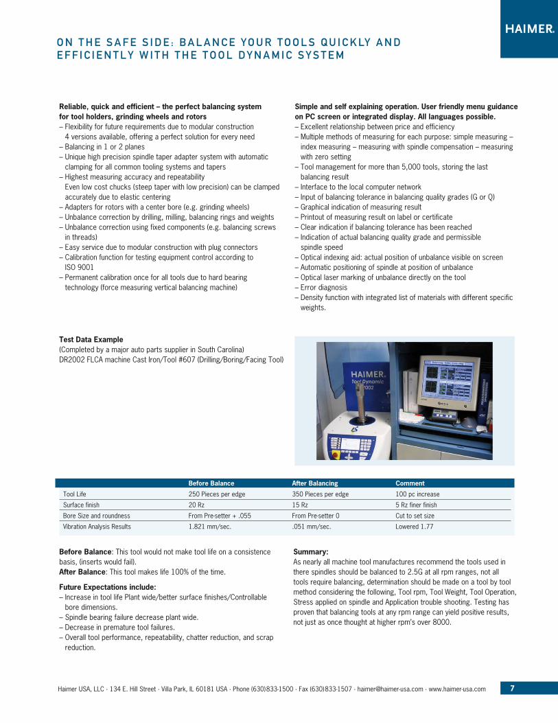
Test Data Example(Completed by a major auto parts supplier in South Carolina)DR2002 FLCA machine Cast Iron/Tool #607 (Drilling/Boring/Facing Tool)
Before Balance After Balancing Comment
Tool Life 250 Pieces per edge 350 Pieces per edge 100 pc increase
Surface finish 20 Rz 15 Rz 5 Rz finer finish
Bore Size and roundness From Pre-setter + .055 From Pre-setter 0 Cut to set size
Vibration Analysis Results 1.821 mm/sec. .051 mm/sec. Lowered 1.77
8 Haimer USA, LLC · 134 E. Hill Street · Villa Park, IL 60181 USA · Phone (630)833-1500 · Fax (630)833-1507 · [email protected] · www.haimer-usa.com
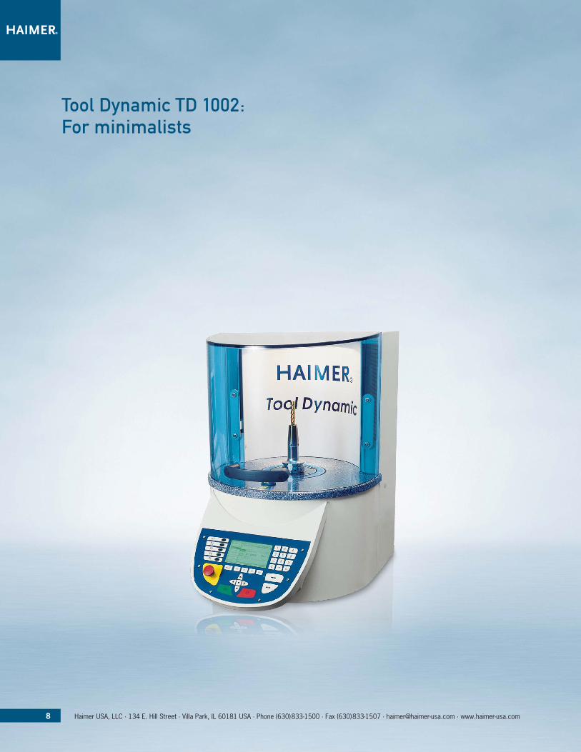
Tool Dynamic TD 1002: for minimalists
9Haimer USA, LLC · 134 E. Hill Street · Villa Park, IL 60181 USA · Phone (630)833-1500 · Fax (630)833-1507 · [email protected] · www.haimer-usa.com
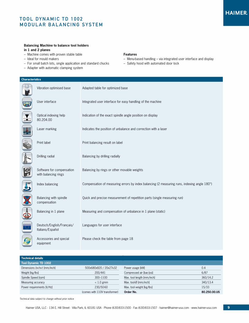
T o o l D y n a M i C T D 1 0 0 2M o D u l a r B a l a n C i n G S y S T e M
Balancing Machine to balance tool holders in 1 and 2 planes – Machine comes with proven stable table – Ideal for mould makers – For small batch lots, single application and standard chucks – Adapter with automatic clamping system
Features – Menu-based handling – via integrated user interface and display – Safety hood with automated door lock
Characteristics
Technical data subject to change without prior notice
Technical details
Tool Dynamic TD 1002
Dimensions bxhxt [mm/inch] 500x680x820 / 20x27x32
Weight [kg/lbs] 200/441
Spindle Speed [rpm] 300–1100
Measuring accuracy < 1.0 gmm
Power requirements [V/Hz] 230/50-60
(comes with 110V transformer)
Power usage [kW] 0.4
Compressed air [bar/psi] 6/87
Max. tool length [mm/inch] 360/14.2
Max. tool-Ø [mm/inch] 340/13.4
Max. tool weight [kg/lbs] 15/33
Order No. 80.250.00.US
Vibration optimised base
Deutsch/English/Français/ Italiano/Español
Balancing in 1 plane
User interface
Optical indexing help80.204.00
Laser marking
Print label
Drilling radial
Index balancing
Balancing with spindle compensation
Software for compensation with balancing rings
Accessories and special equipment
Adapted table for optimized base
Languages for user interface
Integrated user interface for easy handling of the machine
Measuring and compensation of unbalance in 1 plane (static)
Indication of the exact spindle angle position on display
Indicates the position of unbalance and correction with a laser
Print balancing result on label
Balancing by drilling radially
Compensation of measuring errors by index balancing (2 measuring runs, indexing angle 180°)
Quick and precise measurement of repetition parts (single measuring run)
Balancing by rings or other movable weights
Please check the table from page 18

Tool Dynamic TD 2009 economic: for beginners
10 Haimer USA, LLC · 134 E. Hill Street · Villa Park, IL 60181 USA · Phone (630)833-1500 · Fax (630)833-1507 · [email protected] · www.haimer-usa.com
11Haimer USA, LLC · 134 E. Hill Street · Villa Park, IL 60181 USA · Phone (630)833-1500 · Fax (630)833-1507 · [email protected] · www.haimer-usa.com
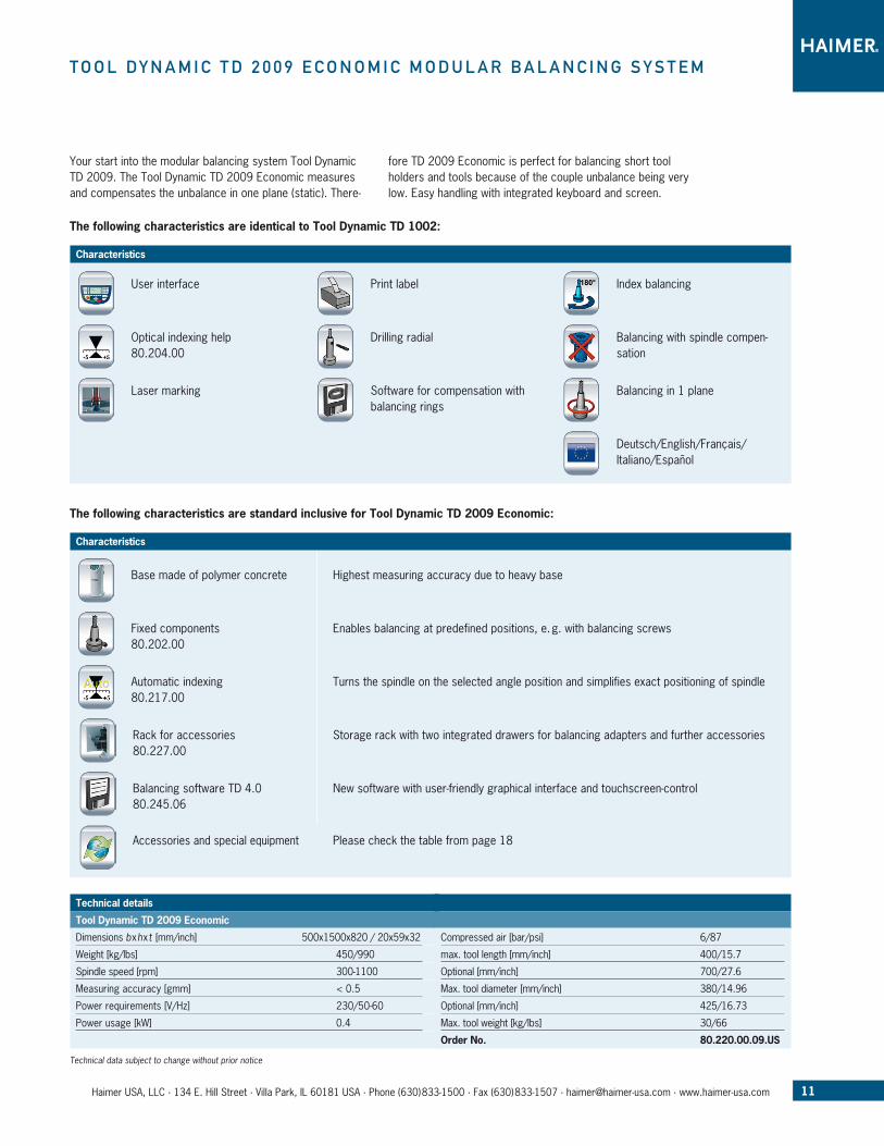
T o o l D y n a M i C T D 2 0 0 9 e C o n o M i C M o D u l a r B a l a n C i n G S y S T e M
Your start into the modular balancing system Tool Dynamic TD 2009. The Tool Dynamic TD 2009 Economic measures and compensates the un balance in one plane (static). There-
fore TD 2009 Economic is perfect for balancing short tool holders and tools because of the couple unbalance being very low. Easy handling with integrated keyboard and screen.
Technical data subject to change without prior notice
Technical details
Tool Dynamic TD 2009 Economic
Dimensions bxhxt [mm/inch] 500x1500x820 / 20x59x32
Weight [kg/lbs] 450/990
Spindle speed [rpm] 300-1100
Measuring accuracy [gmm] < 0.5
Power requirements [V/Hz] 230/50-60
Power usage [kW] 0.4
Compressed air [bar/psi] 6/87
max. tool length [mm/inch] 400/15.7
Optional [mm/inch] 700/27.6
Max. tool diameter [mm/inch] 380/14.96
Optional [mm/inch] 425/16.73
Max. tool weight [kg/lbs] 30/66
Order No. 80.220.00.09.US
The following characteristics are identical to Tool Dynamic TD 1002:
The following characteristics are standard inclusive for Tool Dynamic TD 2009 Economic:
Characteristics
Characteristics
Balancing in 1 planeLaser marking
Optical indexing help80.204.00
Balancing software TD 4.080.245.06
Base made of polymer concrete
Fixed components80.202.00
Automatic indexing80.217.00
Rack for accessories80.227.00
Highest measuring accuracy due to heavy base
Enables balancing at predefined positions, e. g. with balancing screws
Turns the spindle on the selected angle position and simplifies exact positioning of spindle
Storage rack with two integrated drawers for balancing adapters and further accessories
New software with user-friendly graphical interface and touchscreen-control
User interface Print label
Drilling radial
Index balancing
Balancing with spindle compen-sation
Software for compensation with balancing rings
Deutsch/English/Français/Italiano/Español
Accessories and special equipment Please check the table from page 18
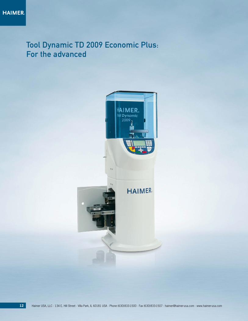
Tool Dynamic TD 2009 economic plus: for the advanced
12 Haimer USA, LLC · 134 E. Hill Street · Villa Park, IL 60181 USA · Phone (630)833-1500 · Fax (630)833-1507 · [email protected] · www.haimer-usa.com

The new TD 2009 Economic Plus is perfect to measure unbal-ance in two planes (dynamic). Long tools have to be balanced in two planes to correct also the couple or dynamic unbalance. Accessories can be clearly arranged in the built in drawers.
Work quickly and error free with laser marking, optical indexing help and automatic indexing of the spindle. The “fixed components” allow to balance with screws at rotors with threaded bores.
The following characteristics are standard inclusive for Tool Dynamic TD 2009 Economic Plus:
Characteristics
Accessories and special equipment
Technical data subject to change without prior notice
Technical details
Tool Dynamic TD 2009 Economic Plus
Dimensions bxhxt [mm/inch] 500x1500x820 / 20x59x32
Weight [kg/lbs] 450/990
Spindle speed [rpm] 300-1100
Measuring accuracy [gmm] < 0.5
Power requirements [V/Hz] 230/50-60
Power usage [kW] 0.4
Compressed air [bar/psi] 6/87
max. tool length [mm/inch] 400/15.7
Optional [mm/inch] 700/27.6
Max. tool diameter [mm/inch] 380/14.96
Optional [mm/inch] 425/16.73
Max. tool weight [kg/lbs] 30/66
Order No. 80.222.00.09.US
Balancing in 2 planes80.252.01
Measuring and compensation of unbalance in 2 planes (dynamic unbalance)
Please check the table from page 18
13Haimer USA, LLC · 134 E. Hill Street · Villa Park, IL 60181 USA · Phone (630)833-1500 · Fax (630)833-1507 · [email protected] · www.haimer-usa.com
T o o l D y n a M i C T D 2 0 0 9 e C o n o M i C p l u SM o D u l a r B a l a n C i n G S y S T e M
The following characteristics are identical to Tool Dynamic TD 2009 Economic:
Characteristics
Balancing in 1 plane
Optical indexing help80.204.00
User interface
Laser marking
Fixed components80.202.00
Automatic indexing80.217.00
Rack for accessories80.227.00
Base made of polymer concrete
Print label
Drilling radial
Index balancing
Balancing with spindle compensa-tion
Software for compensation with balancing rings
Deutsch/English/Français/Italiano/Español
Balancing software TD 4.080.245.06
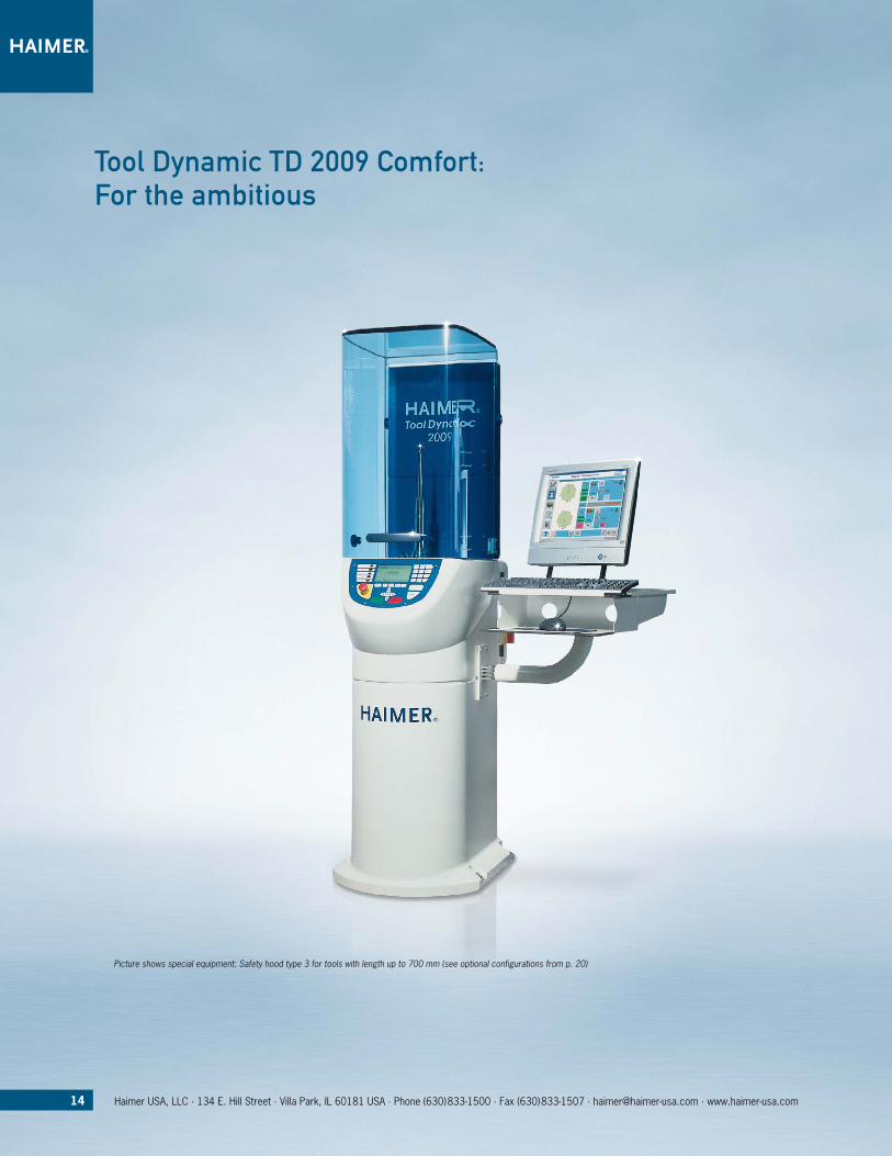
Tool Dynamic TD 2009 Comfort: for the ambitious
14 Haimer USA, LLC · 134 E. Hill Street · Villa Park, IL 60181 USA · Phone (630)833-1500 · Fax (630)833-1507 · [email protected] · www.haimer-usa.com
Picture shows special equipment: Safety hood type 3 for tools with length up to 700 mm (see optional configurations from p. 20)
If you want to use the Tool Dynamic frequently and keep the balancing time as short as possible, you should decide on the TD 2009 Comfort machine. It’s equipped with a PC, keyboard, mouse and monitor. The big screen enables you a fast input of tool data and all the comfort of a graphical user interface – you just balance faster!
In addition the software of the machine offers the possibility to correct the unbalance with the help of a milling program what is very common in practice to correct the un balance.
Milling program80.212.00
T o o l D y n a M i C T D 2 0 0 9 C o M f o r TM o D u l a r B a l a n C i n G S y S T e M
Technical data subject to change without prior notice
Technical details
Tool Dynamic TD 2009 Comfort
Dimensions bxhxt [mm/inch] 1100x1500x820 / 43x59x32
Weight [kg/lbs] 450/990
Spindle speed [rpm] 300-1100
Measuring accuracy [gmm] < 0.5
Power requirements [V/Hz] 230/50-60
Power usage [kW] 0.4
Compressed air [bar/psi] 6/87
max. tool length [mm/inch] 400/15.7
Optional [mm/inch] 700/27.6
Max. tool diameter [mm/inch] 380/14.96
Optional [mm/inch] 425/16.73
Max. tool weight [kg/lbs] 30/66
Order No. 80.224.00.09.US
The following characteristics are identical to Tool Dynamic TD 2009 Economic Plus:
The following characteristics are standard inclusive for Tool Dynamic TD 2009 Comfort:
Characteristics
Characteristics
Balancing in 1 plane
Optical indexing help80.204.00
User interface
Laser marking
Accessories and special equipment
Balancing in 2 planes80.252.01
Fixed components80.202.00
Automatic indexing80.217.00
Rack for accessories80.227.00
Base made of polymer concrete
Print label
Drilling radial
Index balancing
Balancing with spindle compensation
Software for compensation with balancing rings
Deutsch/English/Français/Italiano/Español
User account adminsitration80.245.12
Screen holder80.228.02
TFT screen80.229.02
Milling program allows correction of unbalance via milling
Please check the table from page 18
User administration with individual allocation of user rights
Comfortable tray to place PC-screen and keyboard
Comfortable usage via keyboard for integrated PC(includes TFT screen, keyboard, mouse)
15Haimer USA, LLC · 134 E. Hill Street · Villa Park, IL 60181 USA · Phone (630)833-1500 · Fax (630)833-1507 · [email protected] · www.haimer-usa.com
Balancing software TD 4.080.245.06
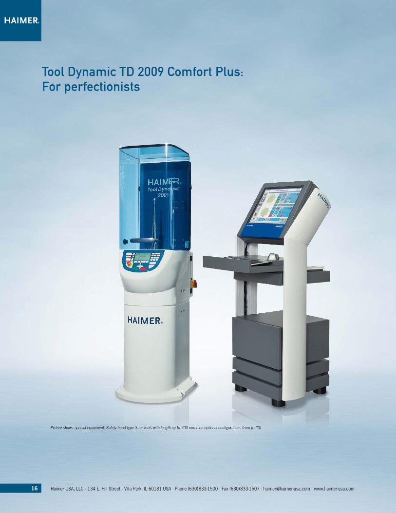
Tool Dynamic TD 2009 Comfort plus: for perfectionists
Picture shows special equipment: Safety hood type 3 for tools with length up to 700 mm (see optional configurations from p. 20)
16 Haimer USA, LLC · 134 E. Hill Street · Villa Park, IL 60181 USA · Phone (630)833-1500 · Fax (630)833-1507 · [email protected] · www.haimer-usa.com

The new Tool Dynamic TD 2009 Comfort Plus offers a maxi-mum of usability and comfort. Using TD 2009 Comfort Plus you will never loose your goal during the balancing prog-ress. You would like to balance your tools efficiently, fast and without being an expert? Then feel free to choose Tool
Dynamic TD 2009 Comfort Plus – optimized touchscreen us-age, integrated PC, comfortable storages for your balancing accessories and a maximum of equipment make balancing fast, convenient and very easy.
Control terminal incl. touchscreen80.233.00
Technical data subject to change without prior notice
Technical details
Tool Dynamic TD 2009 Comfort Plus
Dimensions bxhxt [mm/inch] 1100x1500x820 / 43x59x32
Weight [kg/lbs] 450/990
Spindle speed [rpm] 300-1100
Measuring accuracy [gmm] < 0.5
Power requirements [V/Hz] 230/50-60
Power usage [kW] 0.4
Compressed air [bar/psi] 6/87
max. tool length [mm/inch] 400/15.7
Optional [mm/inch] 700/27.6
Max. tool diameter [mm/inch] 380/14.96
Optional [mm/inch] 425/16.73
Max. tool weight [kg/lbs] 30/66
Order No. 80.226.00.09.US
T o o l D y n a M i C T D 2 0 0 9 C o M f o r T p l u SM o D u l a r B a l a n C i n G S y S T e M
Milling program80.212.00
The following characteristics are identical to Tool Dynamic TD 2009 Comfort:
The following characteristics are standard inclusive for Tool Dynamic TD 2009 Comfort Plus:
Characteristics
Characteristics
Balancing in 1 plane
Optical indexing help80.204.00
User interface
Laser marking
Accessories and special equipment
Balancing in 2 planes80.252.01
Fixed components80.202.00
Automatic indexing80.217.00
Rack for accessories80.227.00
Console for storage of touchscreen, keyboard, mouse, printer, and further accessories (only together with Balancing software TD 4.0)
Please check the table from page 18
Base made of polymer concrete
Print label
Drilling radial
Index balancing
Balancing with spindle compensa-tion
Software for compensation with balancing rings
Deutsch/English/Français/Italiano/Español
Balancing software TD 4.080.245.06
17Haimer USA, LLC · 134 E. Hill Street · Villa Park, IL 60181 USA · Phone (630)833-1500 · Fax (630)833-1507 · [email protected] · www.haimer-usa.com
User account adminsitration80.245.12

18 Haimer USA, LLC · 134 E. Hill Street · Villa Park, IL 60181 USA · Phone (630)833-1500 · Fax (630)833-1507 · [email protected] · www.haimer-usa.com
o p T i o n a l C o n f i G u r aT i o n S
Technical data subject to change without prior notice
Symbol Order No. Article name Description TD 1002 TD 2009 TD 800 Economic Economic Comfort Comfort Plus Plus
included optional — not available
80.205.00 Transformer Transforms 230 Volt single phase power to 110 Volt single phase
— Vibration optimized base
Adapted table for optimized base
— — — — —
— Base made of polymer concrete
Highest measuring accuracy due to heavy base
—
— User interface Integrated user interface for easy handling of the machine
80.204.00 Optical indexing help
Indication of the exact spindle angle position on display
— Laser marking Indicates the position of unbal-ance and correction with a laser
— Print label Print balancing result on label
— Drilling radial Balancing by drilling radially
— Software for compensation with balancing rings
Balancing by rings or other mov-able weights
— Index balancing Compensation of measuring errors by index balancing (2 mea-suring runs, indexing angle 180°)
— Balancing with spin-dle compensation
Quick and precise measurement of repetition parts (single measur-ing run)
— Balancing in 1 plane Measuring and compensation of unbalance in 1 plane (static)
80.252.01 Balancing in 2 planes
Measuring and compensation of unbalance in 2 planes (dynamic unbalance)
80.202.00 Fixed components Enables balancing at predefined positions, e. g. with balancing screws
19Haimer USA, LLC · 134 E. Hill Street · Villa Park, IL 60181 USA · Phone (630)833-1500 · Fax (630)833-1507 · [email protected] · www.haimer-usa.com
Technical data subject to change without prior notice included optional — not available
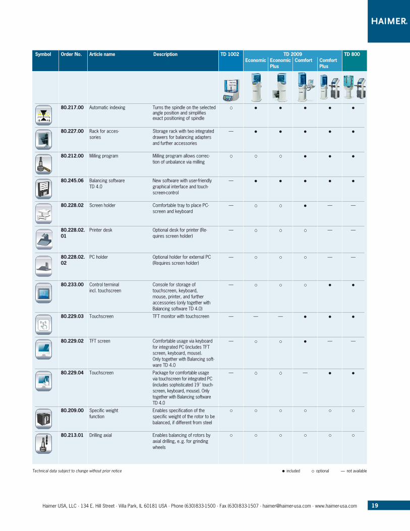
80.217.00 Automatic indexing Turns the spindle on the selected angle position and simplifies exact positioning of spindle
80.227.00 Rack for acces-sories
Storage rack with two integrated draw ers for balancing adapters and further accessories
—
80.212.00 Milling program Milling program allows correc-tion of unbalance via milling
80.245.06 Balancing software TD 4.0
New software with user-friendly graphical interface and touch-screen-control
—
80.228.02 Screen holder Comfortable tray to place PC-screen and keyboard
— — —
80.228.02.01
Printer desk Optional desk for printer (Re-quires screen holder)
— — —
80.228.02.02
PC holder Optional holder for external PC (Requires screen holder)
— — —
80.233.00 Control terminal incl. touchscreen
Console for storage of touchscreen, keyboard, mouse, printer, and further accessories (only together with Balancing software TD 4.0)
—
80.229.03 Touchscreen TFT monitor with touchscreen — — —
80.229.02 TFT screen Comfortable usage via keyboard for integrated PC (includes TFT screen, keyboard, mouse).Only together with Balancing soft-ware TD 4.0
— — —
80.229.04 Touchscreen Package for comfortable usage via touchscreen for integrated PC (includes sophisticated 19˝ touch-screen, keyboard, mouse). Only together with Balancing software TD 4.0
— —
80.209.00 Specific weight function
Enables specification of the specific weight of the rotor to be balanced, if different from steel
80.213.01 Drilling axial Enables balancing of rotors by axial drilling, e. g. for grinding wheels
Symbol Order No. Article name Description TD 1002 TD 2009 TD 800 Economic Economic Comfort Comfort Plus Plus
20 Haimer USA, LLC · 134 E. Hill Street · Villa Park, IL 60181 USA · Phone (630)833-1500 · Fax (630)833-1507 · [email protected] · www.haimer-usa.com
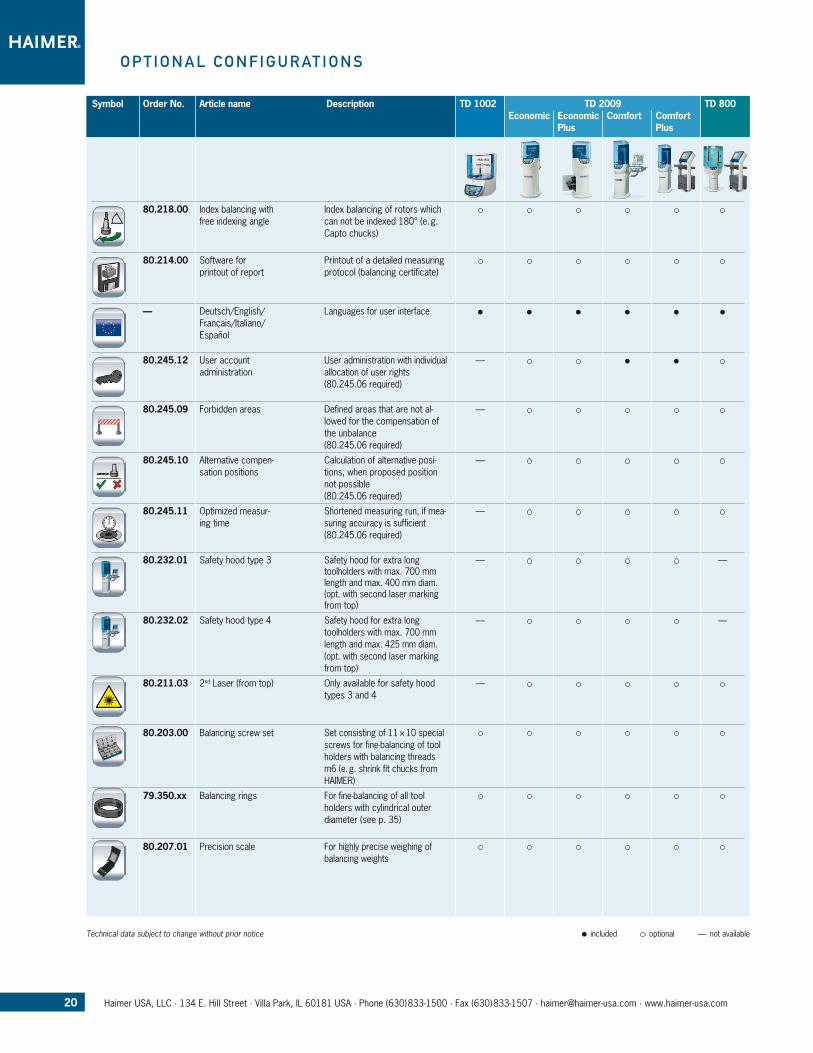
80.218.00 Index balancing with free indexing angle
Index balancing of rotors which can not be indexed 180° (e. g. Capto chucks)
80.214.00 Software for printout of report
Printout of a detailed measuring protocol (balancing certificate)
— Deutsch/English/Français/Italiano/Español
Languages for user interface
80.245.12 User account administration
User administration with individual allocation of user rights(80.245.06 required)
—
80.245.09 Forbidden areas Defined areas that are not al-lowed for the compensation of the unbalance(80.245.06 required)
—
80.245.10 Alternative compen-sation positions
Calculation of alternative posi-tions, when proposed position not possible(80.245.06 required)
—
80.245.11 Optimized measur-ing time
Shortened measuring run, if mea-suring accuracy is sufficient(80.245.06 required)
—
80.232.01 Safety hood type 3 Safety hood for extra long toolholders with max. 700 mm length and max. 400 mm diam. (opt. with second laser marking from top)
— —
80.232.02 Safety hood type 4 Safety hood for extra long toolholders with max. 700 mm length and max. 425 mm diam. (opt. with second laser marking from top)
— —
80.211.03 2nd Laser (from top) Only available for safety hood types 3 and 4
—
80.203.00 Balancing screw set Set consisting of 11 × 10 special screws for fine-balancing of tool holders with balancing threads m6 (e. g. shrink fit chucks from HAIMER)
79.350.xx Balancing rings For fine-balancing of all tool holders with cylindrical outer diameter (see p. 35)
80.207.01 Precision scale For highly precise weighing of balancing weights
Symbol Order No. Article name Description TD 1002 TD 2009 TD 800 Economic Economic Comfort Comfort Plus Plus
o p T i o n a l C o n f i G u r aT i o n S
Technical data subject to change without prior notice included optional — not available
21Haimer USA, LLC · 134 E. Hill Street · Villa Park, IL 60181 USA · Phone (630)833-1500 · Fax (630)833-1507 · [email protected] · www.haimer-usa.com
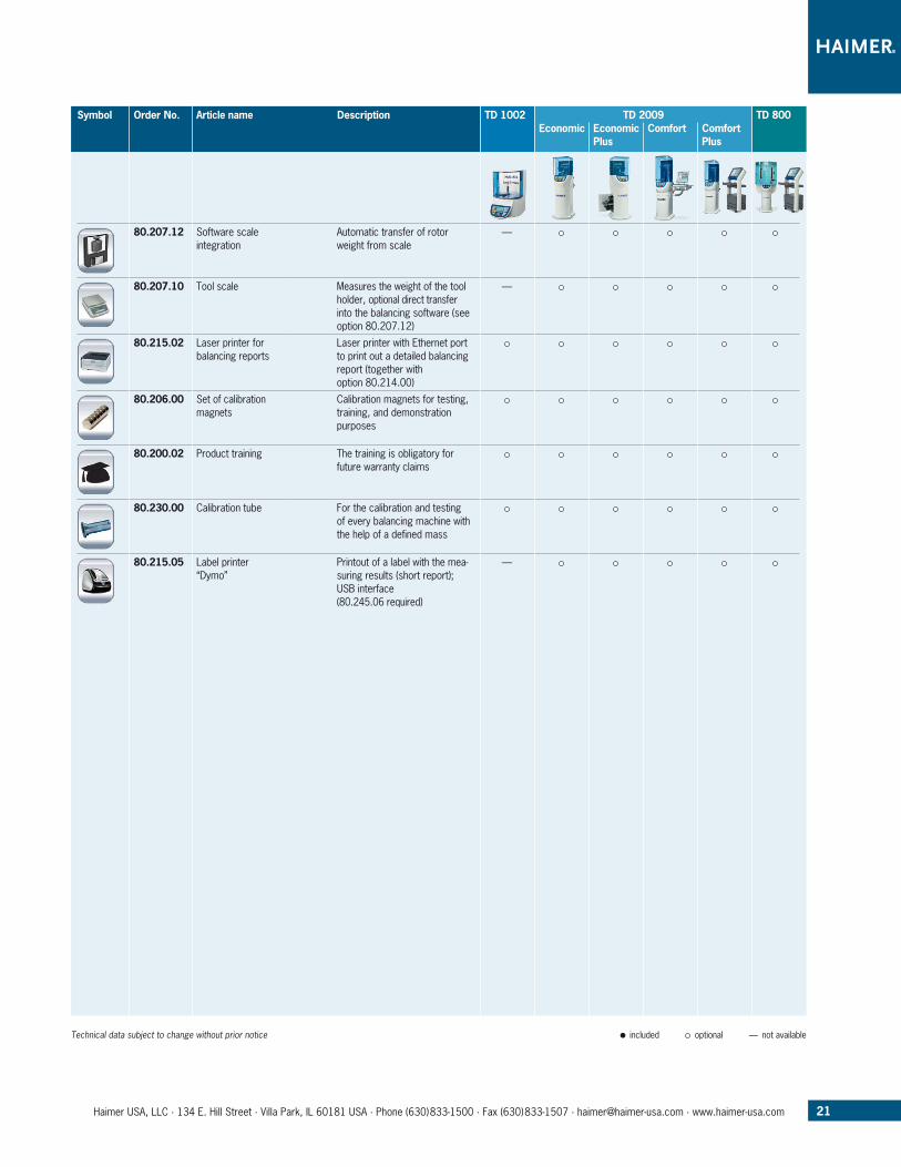
80.207.12 Software scale integration
Automatic transfer of rotor weight from scale
—
80.207.10 Tool scale Measures the weight of the tool holder, optional direct transfer into the balancing software (see option 80.207.12)
—
80.215.02 Laser printer for balancing reports
Laser printer with Ethernet port to print out a detailed balancing report (together with option 80.214.00)
80.206.00 Set of calibration magnets
Calibration magnets for testing, training, and demonstration purposes
80.200.02 Product training The training is obligatory for future warranty claims
80.230.00 Calibration tube For the calibration and testing of every balancing machine with the help of a defined mass
80.215.05 Label printer“Dymo”
Printout of a label with the mea-suring results (short report); USB interface(80.245.06 required)
—
Symbol Order No. Article name Description TD 1002 TD 2009 TD 800 Economic Economic Comfort Comfort Plus Plus
Technical data subject to change without prior notice included optional — not available
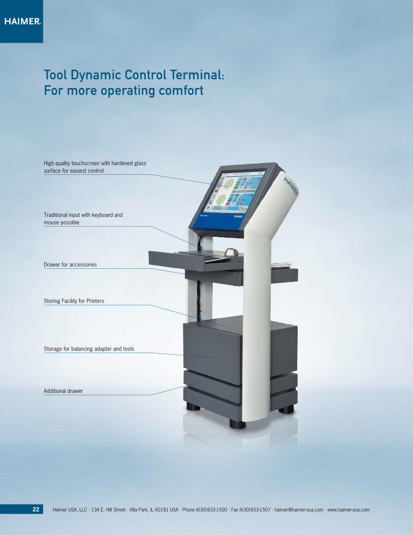
High quality touchscreen with hardened glass surface for easiest control
Traditional input with keyboard and mouse possible
Storing Facility for Printers
Drawer for accessories
Additional drawer
Storage for balancing adapter and tools
Tool Dynamic Control Terminal:for more operating comfort
22 Haimer USA, LLC · 134 E. Hill Street · Villa Park, IL 60181 USA · Phone (630)833-1500 · Fax (630)833-1507 · [email protected] · www.haimer-usa.com
23Haimer USA, LLC · 134 E. Hill Street · Villa Park, IL 60181 USA · Phone (630)833-1500 · Fax (630)833-1507 · [email protected] · www.haimer-usa.com
T o o l D y n a M i C T D S o f T Wa r e 4 . 0
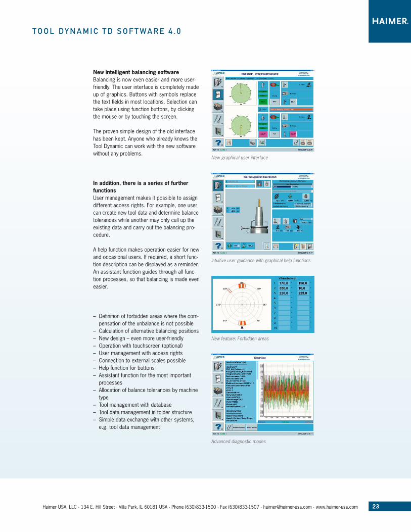
New intelligent balancing softwareBalancing is now even easier and more user-friendly. The user interface is completely made up of graphics. Buttons with symbols replace the text fields in most locations. Selection can take place using function buttons, by clicking the mouse or by touching the screen.
The proven simple design of the old interface has been kept. Anyone who already knows the Tool Dynamic can work with the new software without any problems.
In addition, there is a series of further functionsUser management makes it possible to assign different access rights. For example, one user can create new tool data and determine balance tolerances while another may only call up the existing data and carry out the balancing pro-cedure.
A help function makes operation easier for new and occasional users. If required, a short func-tion description can be displayed as a reminder. An assistant function guides through all func-tion processes, so that balancing is made even easier.
– Definition of forbidden areas where the com-pensation of the unbalance is not possible
– Calculation of alternative balancing positions – New design – even more user-friendly – Operation with touchscreen (optional) – User management with access rights – Connection to external scales possible – Help function for buttons – Assistant function for the most important processes
– Allocation of balance tolerances by machine type
– Tool management with database – Tool data management in folder structure – Simple data exchange with other systems, e.g. tool data management
New graphical user interface
Intuitive user guidance with graphical help functions
New feature: Forbidden areas
Advanced diagnostic modes
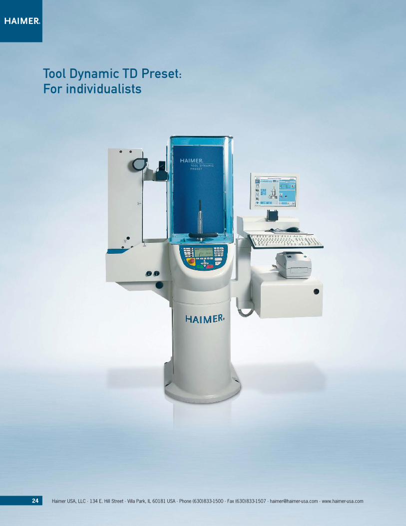
Tool Dynamic TD preset: for individualists
24 Haimer USA, LLC · 134 E. Hill Street · Villa Park, IL 60181 USA · Phone (630)833-1500 · Fax (630)833-1507 · [email protected] · www.haimer-usa.com
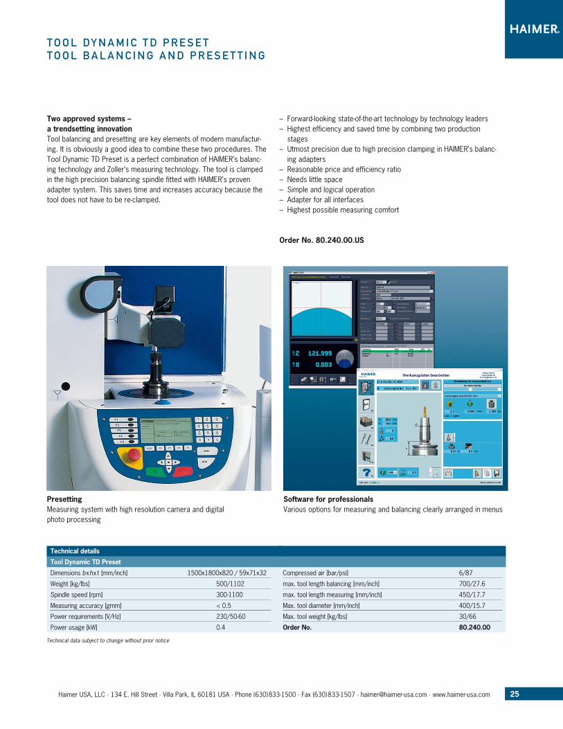
Two approved systems – a trendsetting innovationTool balancing and presetting are key elements of modern manufactur-ing. It is obviously a good idea to combine these two procedures. The Tool Dynamic TD Preset is a perfect combination of HAIMER’s balanc-ing technology and Zoller’s measuring technology. The tool is clamped in the high pre cision balancing spindle fitted with HAIMER’s proven adapter system. This saves time and increases accuracy because the tool does not have to be re-clamped.
– Forward-looking state-of-the-art technology by technology leaders – Highest efficiency and saved time by combining two production stages
– Utmost precision due to high precision clamping in HAIMER’s balanc-ing adapters
– Reasonable price and efficiency ratio – Needs little space – Simple and logical operation – Adapter for all interfaces – Highest possible measuring comfort
Order No. 80.240.00.US
T o o l D y n a M i C T D p r e S e TT o o l B a l a n C i n G a n D p r e S e T T i n G
PresettingMeasuring system with high resolution camera and digital photo processing
Software for professionalsVarious options for measuring and balancing clearly arranged in menus
25Haimer USA, LLC · 134 E. Hill Street · Villa Park, IL 60181 USA · Phone (630)833-1500 · Fax (630)833-1507 · [email protected] · www.haimer-usa.com
Technical data subject to change without prior notice
Technical details
Tool Dynamic TD Preset
Dimensions bxhxt [mm/inch] 1500x1800x820 / 59x71x32
Weight [kg/lbs] 500/1102
Spindle speed [rpm] 300-1100
Measuring accuracy [gmm] < 0.5
Power requirements [V/Hz] 230/50-60
Power usage [kW] 0.4
Compressed air [bar/psi] 6/87
max. tool length balancing [mm/inch] 700/27.6
max. tool length measuring [mm/inch] 450/17.7
Max. tool diameter [mm/inch] 400/15.7
Max. tool weight [kg/lbs] 30/66
Order No. 80.240.00
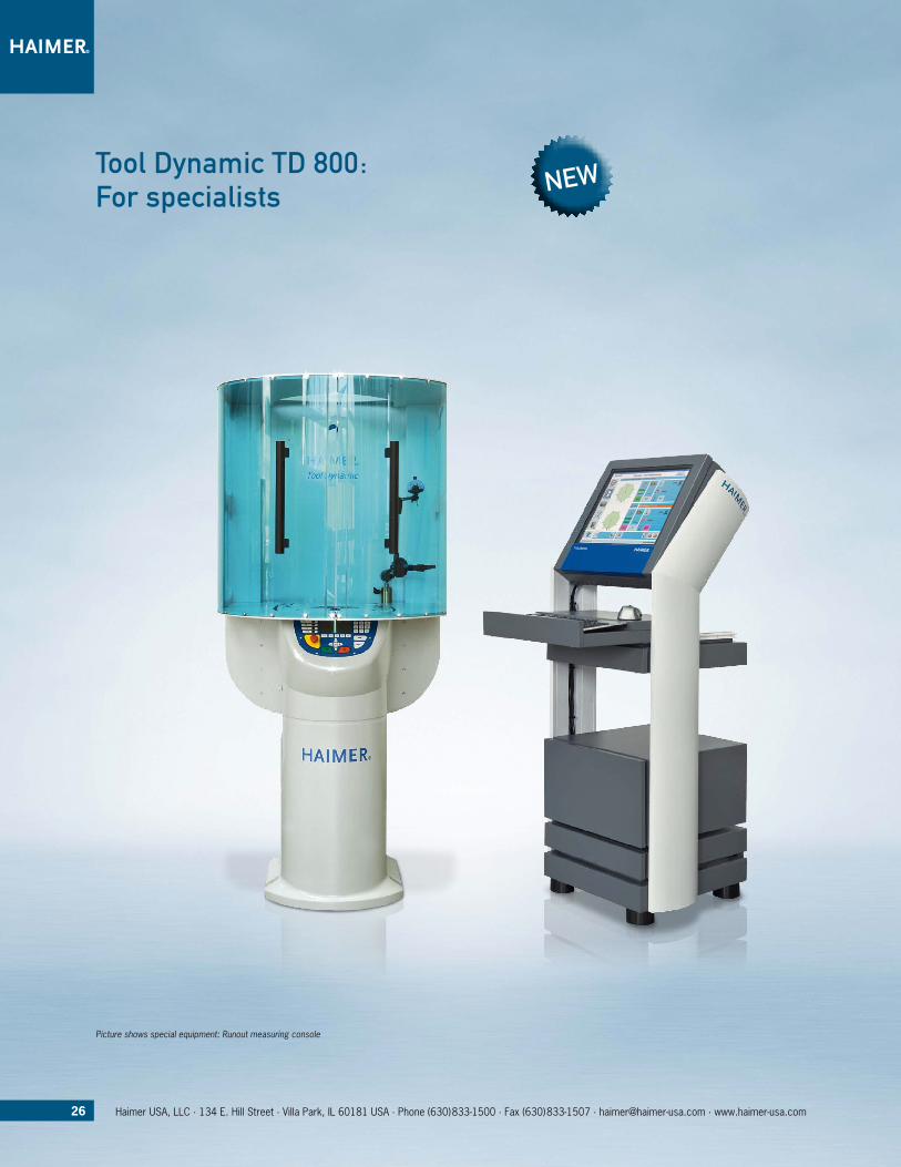
Tool Dynamic TD 800: for specialists
26 Haimer USA, LLC · 134 E. Hill Street · Villa Park, IL 60181 USA · Phone (630)833-1500 · Fax (630)833-1507 · [email protected] · www.haimer-usa.com
Picture shows special equipment: Runout measuring console
New
Technical details
Tool Dynamic TD 800
Dimensions bxhxt [mm/inch] 1500 × 1910 × 900 / 59x75x36
Weight [kg/lbs] 550/1210
Spindle speed [rpm] 200-1100
Measuring accuracy [gmm] < 0.5
Power requirements [V/Hz] 230/50-60
Power usage [kW] 1.0
Compressed air [bar/psi] 5 – 6/87
Air consumption [l/h] 30
max. tool length [mm/inch] 750/29.5
max. tool diameter [mm/inch] 800/31.5
max. tool weight [kg/lbs] 110/242
Order No. 80.270.00
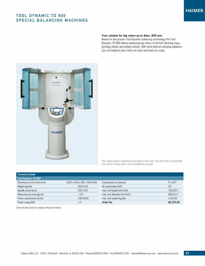
T o o l D y n a M i C T D 8 0 0S p e C i a l B a l a n C i n G M a C h i n e S
Technical data subject to change without prior notice
Your solution for big rotors up to diam. 800 mmBased on the proven Tool Dynamic balancing technology the Tool Dynamic TD 800 allows balancing big rotors of all kind. Bearing rings, grinding wheels and turbine wheels. With hand tailored clamping adapters you can balance your rotors as easy and quick as usual.
The safety hood is segmented and opens to the side. Thus the rotor is accessible from above. Heavy parts can be handled by a crane.
27Haimer USA, LLC · 134 E. Hill Street · Villa Park, IL 60181 USA · Phone (630)833-1500 · Fax (630)833-1507 · [email protected] · www.haimer-usa.com
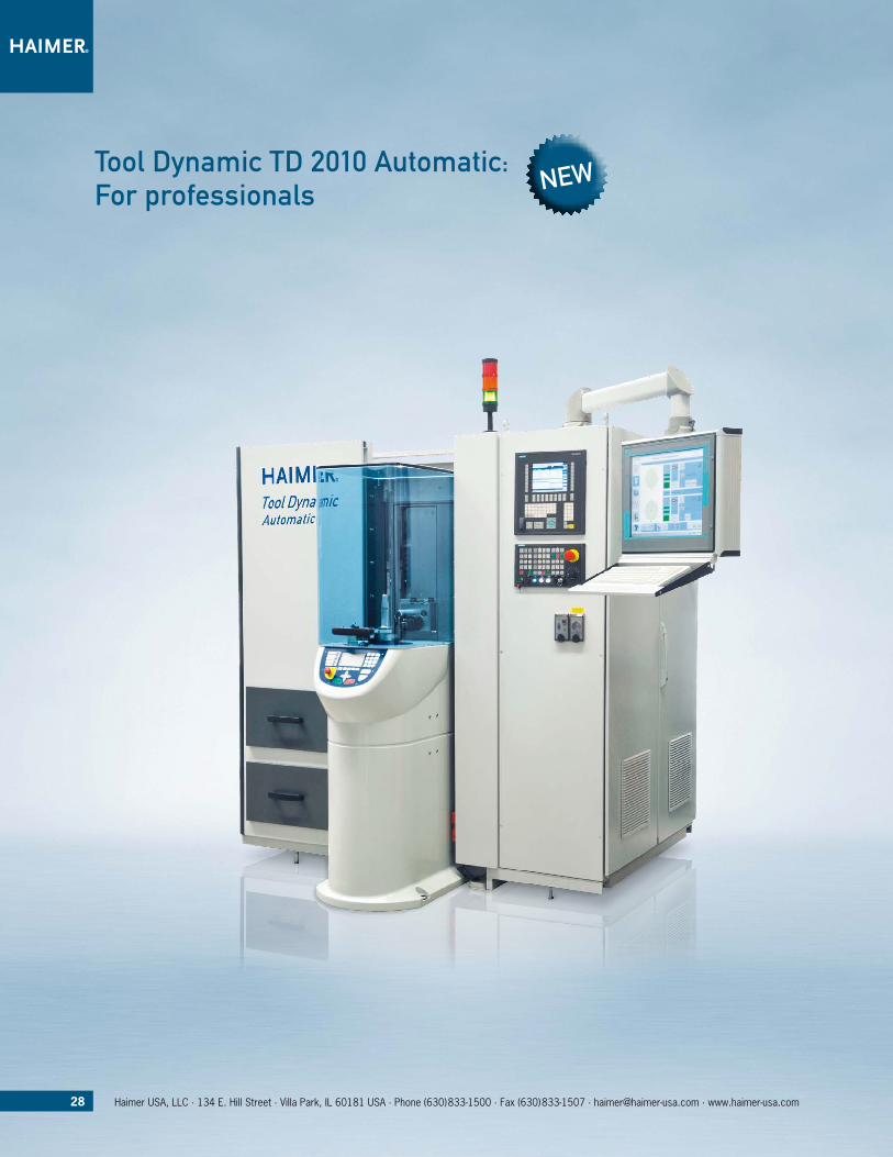
Tool Dynamic TD 2010 automatic: for professionals
28 Haimer USA, LLC · 134 E. Hill Street · Villa Park, IL 60181 USA · Phone (630)833-1500 · Fax (630)833-1507 · [email protected] · www.haimer-usa.com
New
T o o l D y n a M i C T D 2 0 1 0 a u T o M aT i Ca u T o M aT i C B a l a n C i n G T e C h n o l o G y
The new Tool Dynamic TD 2010 Automatic
The new Tool Dynamic TD 2010 Automatic is a truly universal CNC-based balancing machine with automated correction of the unbalance. It automatically compensates the unbalance in one or two planes by drilling, milling or grinding. The machine can work vertically and horizontally.
The balancing machine is controlled by an integrated 19’’ touch-screen. The numerical control is a Siemens 840DSL, which can be accessed simultaneously with the balancing software.
Automatic Balancing – that’s how it works
After measuring the unbalance the software calculates how deep the machine must drill, mill or grind in order to compensate the unbalance. The balancing spindle turns into the correct position. The integrated CNC unit moves to the pre-selected balancing plane and automatically removes the appropriate amount of material. Done.
Balancing could not be any quicker or easier. Errors, such as those caused by incorrect marking on the tool holder or through inadver-tently incorrect drilling depths are no longer an issue. – Measures and compensates unbalance in one step – Rapid, easy and economic – No incorrect drilling on the rotor – Integration into automatic production lines is possible – Specific software for particular methods of balancing available
Tool Dynamic TD 2010 Automatic – automatic vertical CNC based balancing machine: Maximum comfort, maximum process reliability with highest efficiency and precision.
Order No. 80.260.00
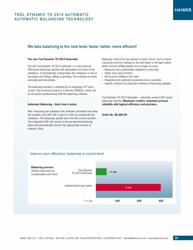
We take balancing to the next level: faster, better, more efficient!
Tool Dynamic TD 2010 Automatic
Improve your efficiency: balancing in record time!
standard balancing system
Time [s] 100 200 300
5 min
< 1 min
Balancing process: Simple measuring run, compensation and check
29Haimer USA, LLC · 134 E. Hill Street · Villa Park, IL 60181 USA · Phone (630)833-1500 · Fax (630)833-1507 · [email protected] · www.haimer-usa.com

30 Haimer USA, LLC · 134 E. Hill Street · Villa Park, IL 60181 USA · Phone (630)833-1500 · Fax (630)833-1507 · [email protected] · www.haimer-usa.com
T o o l D y n a M i C T D 2 0 1 0 a u T o M aT i Cp r o D u C T f e aT u r e S
your benefits at a glance
n Correction of unbalance is fully automated by drilling, milling or grinding in one or two planes with the help of an integrated simultaneous 4 Axis CNC machine tool
n Integrated and exchangeable balancing adapters clamp rotors with highest precision. There are standard adapters for all common interfaces and customized solutions for special purposes
n Gripper for automated indexing (optional). It can be mounted without any additional tools and changed together with the balancing adapter
n Chips are removed by exhaust (suction) equipment
n Central lubrication enables a nearly maintenance free 3 shift use
n Balancing spindle and control box are cooled
n Dynamic measuring mode enables shortest measuring times – balance and control your rotors in record time!
n Simple measuring mode: Measuring, drilling and checking in less than 1 minute!
n Integration of robot unit is possible – embody your balancing machine in your production line!
n Intelligent software allows the fast and efficient re-balancing of already balanced rotors
Automated compensation of unbalance via CNC machining unit Integrated balancing adapter and gripper for automatic index measuring

31Haimer USA, LLC · 134 E. Hill Street · Villa Park, IL 60181 USA · Phone (630)833-1500 · Fax (630)833-1507 · [email protected] · www.haimer-usa.com
T o o l D y n a M i C T D 2 0 1 0 a u T o M aT i Cp r o D u C T f e aT u r e S
Technical data
Measuring accuracy
Measuring accuracy < 0.5 gmm
Limitation of the rotor
Max. diameter (mm/inch) 400 / 15.74
Max. length (mm/inch) 600 / 23.6
Max. weight (kg/lbs) 50 / 110
Operational range
X-axis (mm/inch) 160 / 6.3
Y-axis (mm/inch) 400 / 15.74
Z-axis (mm/inch) 250 / 9.8
B-axis 360°
Rapid mode 20 m/min on all axis
Balancing spindle
Max. RPM 1100 U/min/rpm
Max. torque 35 Nm
CNC unit
Interface VDI 30
Max. engine speed 6000 U/min adjustable
Max. torque 15 Nm at S3-25%
Max. drilling capacity (mm/inch) Ø 10 mm / 3/8“ in hardened steel with HRC 60
Operational range of rotor in horizontal mode
Max. diameter (mm/inch) 400 / 15.74
Max. height (mm/inch) 250 / 9.8
Operational range of rotor in vertical mode
Max. diameter (mm/inch) 400 / 15.74
Max. height (mm/inch) 280 / 11.0
Technical data subject to change without prior notice
Integrated control and balancing software
32 Haimer USA, LLC · 134 E. Hill Street · Villa Park, IL 60181 USA · Phone (630)833-1500 · Fax (630)833-1507 · [email protected] · www.haimer-usa.com
a p p l i C aT i o n e x a M p l e S
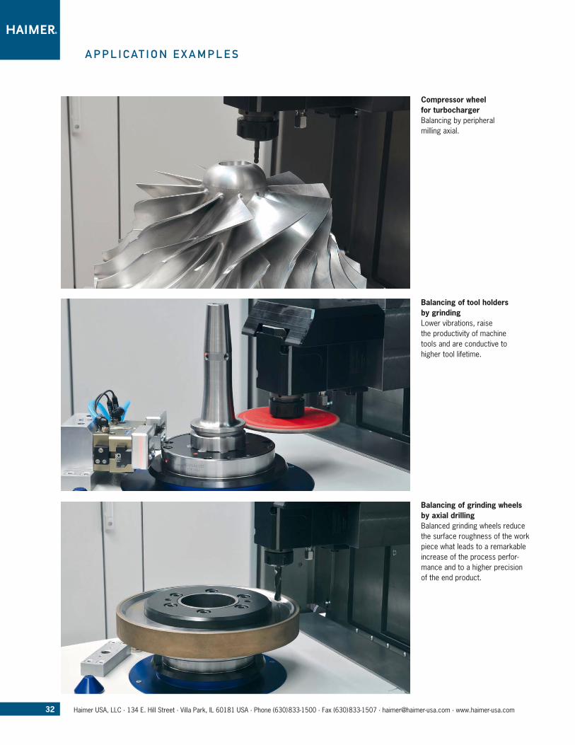
Compressor wheel for turbochargerBalancing by peri pheral milling axial.
Balancing of tool holders by grindingLower vibrations, raise the productivity of machine tools and are conductive to higher tool lifetime.
Balancing of grinding wheels by axial drillingBalanced grinding wheels reduce the surface roughness of the work piece what leads to a remarkable increase of the process perfor-mance and to a higher precision of the end product.
33Haimer USA, LLC · 134 E. Hill Street · Villa Park, IL 60181 USA · Phone (630)833-1500 · Fax (630)833-1507 · [email protected] · www.haimer-usa.com
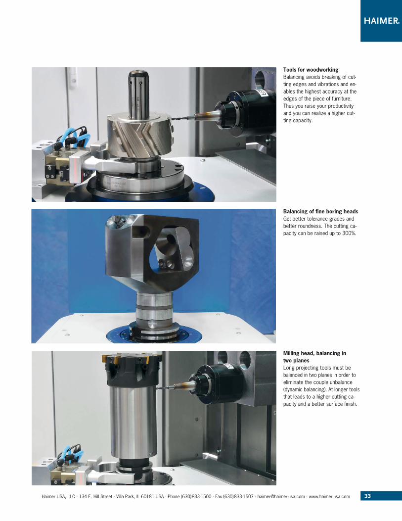
Tools for woodworkingBalancing avoids breaking of cut-ting edges and vibrations and en-ables the highest accuracy at the edges of the piece of furniture. Thus you raise your productivity and you can realize a higher cut-ting capacity.
Balancing of fine boring heads Get better tolerance grades and better roundness. The cutting ca-pacity can be raised up to 300%.
Milling head, balancing in two planes Long projecting tools must be balanced in two planes in order to eliminate the couple unbalance (dynamic balancing). At longer tools that leads to a higher cutting ca-pacity and a better surface finish.
34 Haimer USA, LLC · 134 E. Hill Street · Villa Park, IL 60181 USA · Phone (630)833-1500 · Fax (630)833-1507 · [email protected] · www.haimer-usa.com
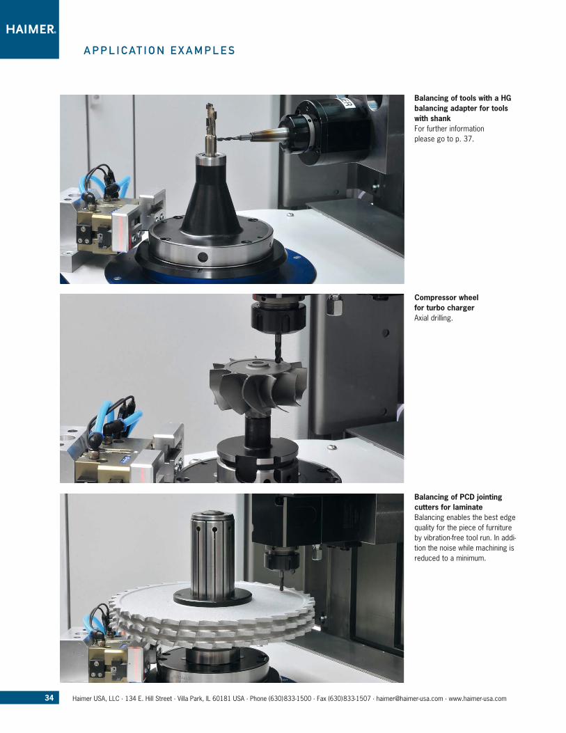
Balancing of tools with a HG balancing adapter for tools with shankFor further information please go to p. 37.
Compressor wheel for turbo chargerAxial drilling.
Balancing of PCD jointing cutters for laminateBalancing enables the best edge quality for the piece of furniture by vibration-free tool run. In addi-tion the noise while machining is reduced to a minimum.
a p p l i C aT i o n e x a M p l e S

35Haimer USA, LLC · 134 E. Hill Street · Villa Park, IL 60181 USA · Phone (630)833-1500 · Fax (630)833-1507 · [email protected] · www.haimer-usa.com
B a l a n C i n G a D a p T e r h S K
– µm precise clamping for highest measuring accuracy and repeatability
– Easy and quickest changing due to compact design
HSK balancing adapter with automatic clamping system
HSK interface Adapter Order No. Analogy Description
HSK 25
E 80.201.E25.00 Adapter for HSK-E25 with clamping system
HSK 32
A 80.201.A32.00 Adapter for HSK-A32 with clamping systemB 80.201.E25.00 B32 = E25 Adapter for HSK-E25 with clamping systemC 80.201.A32.00 C32 = A32 Adapter for HSK-A32 with clamping systemD 80.201.E25.00 D32 = E25 Adapter for HSK-E25 with clamping systemE 80.201.E32.00 Adapter for HSK-E32 with clamping systemF 80.201.E25.00 F32 = E25 Adapter for HSK-E25 with clamping system
HSK 40
A 80.201.A40.00 Adapter for HSK-A40 with clamping systemB 80.201.E32.00 B40 = E32 Adapter for HSK-E32 with clamping systemC 80.201.A40.00 C40 = A40 Adapter for HSK-A40 with clamping systemD 80.201.E32.00 D40 = E32 Adapter for HSK-E32 with clamping systemE 80.201.E40.00 Adapter for HSK-E40 with clamping systemF 80.201.E32.00 F40 = E32 Adapter for HSK-E32 with clamping system
HSK 50
A 80.201.A50.00 Adapter for HSK-A50 with clamping systemB 80.201.E40.00 B50 = E40 Adapter for HSK-E40 with clamping systemC 80.201.A50.00 C50 = A50 Adapter for HSK-A50 with clamping systemD 80.201.E40.00 D50 = E40 Adapter for HSK-E40 with clamping systemE 80.201.E50.00 Adapter for HSK-E50 with clamping systemF 80.201.E40.00 F50 = E40 Adapter for HSK-E40 with clamping system
HSK 63
A 80.201.A63.00 Adapter for HSK-A63 with clamping systemB 80.201.E50.00 B63 = E50 Adapter for HSK-E50 with clamping systemC 80.201.A63.00 C63 = A63 Adapter for HSK-A63 with clamping systemD 80.201.E50.00 D63 = E50 Adapter for HSK-E50 with clamping systemE 80.201.E63.00 Adapter for HSK-E63 with clamping systemF 80.201.E50.00 F63 = E50 Adapter for HSK-E50 with clamping system
Weinig
Weinig 80.201.W63.00 Adapter for Weinig tool holder
HSK 80
A 80.201.A80.00 Adapter for HSK-A80 with clamping systemB 80.201.E63.00 B80 = E63 Adapter for HSK-E63 with clamping systemC 80.201.A80.00 C80 = A80 Adapter for HSK-A80 with clamping systemD 80.201.E63.00 D80 = E63 Adapter for HSK-E63 with clamping systemE 80.201.E80.00 Adapter for HSK-E80 with clamping systemF 80.201.E63.00 F80 = E63 Adapter for HSK-E63 with clamping system
HSK 100
A 80.201.A10.00 Adapter for HSK-A100 with clamping systemB 80.201.E80.00 B100 = E80 Adapter for HSK-E80 with clamping systemC 80.201.A10.00 C100 = A100 Adapter for HSK-A100 with clamping systemD 80.201.E80.00 D100 = E80 Adapter for HSK-E80 with clamping systemE 80.201.E10.00 Adapter for HSK-E100 with clamping systemF 80.201.E80.00 F100 = E80 Adapter for HSK-E80 with clamping system
HSK 125
A 80.201.A125.00 Adapter for HSK-A125 with clamping system
Technical data subject to change without prior notice
36 Haimer USA, LLC · 134 E. Hill Street · Villa Park, IL 60181 USA · Phone (630)833-1500 · Fax (630)833-1507 · [email protected] · www.haimer-usa.com
1) BBT: also suitable for BIG-Plus Technical data subject to change without prior notice
SK/BT/CAT/BBT balancing adapter with automatic clamping system
Order No. for taper size for pull stud
80.201.330.01 SK30/BT30/BBT301) thread M12
80.201.330.01.IN CAT30 thread 1/2”-13
80.201.330.02 SK30 DIN 69872; ISO 7388-3, form AF/AD/AC
80.201.330.02 BT30/BBT301) MAS 30°/45°/90°; ISO 7388-3, form JD/JF
80.201.330.04 SK30 ISO 7388-3, form UF/UD/UC
80.201.140.01 SK40 DIN 2080 thread M16
80.201.340.01 SK40/BT40/BBT401) thread M16
80.201.340.01.IN CAT40 thread 5/8”-11
80.201.340.02 CAT40/SK40 DIN 69872; ISO 7388-3, form AF/AD/AC
80.201.340.02 BT40/BBT401) JIS B6339
80.201.340.04 CAT40/SK40 ISO 7388-3, form UF/UD/UC
80.201.340.06 BT40 MAS 30°/45°/90°; ISO 7388-3, form JD/JF
80.201.150.01 SK50 DIN 2080 thread M24
80.201.350.01 SK50/BT50/BBT501) thread M24
80.201.350.01.IN CAT50 thread 1”-8
80.201.350.02 CAT50/SK50 DIN 69872; ISO 7388-3, form AF/AD/AC
80.201.350.02 BT50/BBT501) JIS B6339
80.201.350.04 CAT50/SK50 ISO 7388-3, form UF/UD/UC
80.201.350.06 BT50/BBT501) MAS 30°/45°/90°; ISO 7388-3, form JD/ JF
B a l a n C i n G a D a p T e r S K / B T / C aT / B B T / C a p T o / K M
Balancing adapter Capto with automatic clamping system
Order No. for taper size
80.201.9C3.10 Capto C3
80.201.9C4.10 Capto C4
80.201.9C5.10 Capto C5
80.201.9C6.10 Capto C6
80.201.9C8.10 Capto C8
80.201.9C10.10 Capto C10
Balancing adapter KM with automatic clamping system
Order No. for taper size
80.201.KM40.00 KM40
80.201.KM50.00 KM50
80.201.KM63.00 KM63
80.201.KM80.00 KM80
80.201.KM100.00 KM100
80.201.KM125.00 KM125 (upon request)
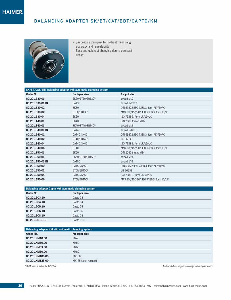
– µm precise clamping for highest measuring accuracy and repeatability
– Easy and quickest changing due to compact design
37Haimer USA, LLC · 134 E. Hill Street · Villa Park, IL 60181 USA · Phone (630)833-1500 · Fax (630)833-1507 · [email protected] · www.haimer-usa.com
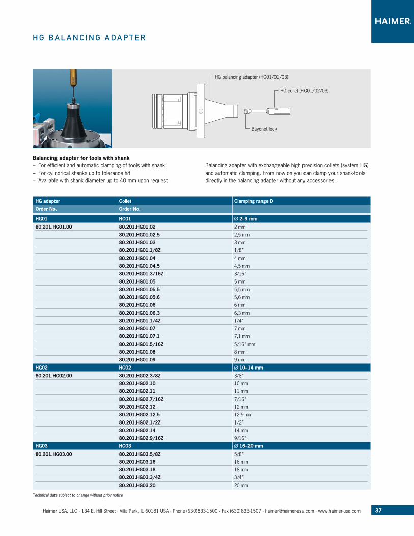
h G B a l a n C i n G a D a p T e r
Balancing adapter for tools with shank – For efficient and automatic clamping of tools with shank – For cylindrical shanks up to tolerance h8 – Available with shank diameter up to 40 mm upon request
Balancing adapter with exchangeable high precision collets (system HG) and automatic clamping. From now on you can clamp your shank-tools directly in the balancing adapter without any accessories.
HG adapter Collet Clamping range D
Order No. Order No.
HG01 HG01 Ø 2–9 mm
80.201.HG01.00 80.201.HG01.02 2 mm
80.201.HG01.02.5 2,5 mm
80.201.HG01.03 3 mm
80.201.HG01.1/8Z 1/8 ”
80.201.HG01.04 4 mm
80.201.HG01.04.5 4,5 mm
80.201.HG01.3/16Z 3/16 ”
80.201.HG01.05 5 mm
80.201.HG01.05.5 5,5 mm
80.201.HG01.05.6 5,6 mm
80.201.HG01.06 6 mm
80.201.HG01.06.3 6,3 mm
80.201.HG01.1/4Z 1/4 ”
80.201.HG01.07 7 mm
80.201.HG01.07.1 7,1 mm
80.201.HG01.5/16Z 5/16 ” mm
80.201.HG01.08 8 mm
80.201.HG01.09 9 mm
HG02 HG02 Ø 10–14 mm
80.201.HG02.00 80.201.HG02.3/8Z 3/8 ”
80.201.HG02.10 10 mm
80.201.HG02.11 11 mm
80.201.HG02.7/16Z 7/16 ”
80.201.HG02.12 12 mm
80.201.HG02.12.5 12,5 mm
80.201.HG02.1/2Z 1/2 ”
80.201.HG02.14 14 mm
80.201.HG02.9/16Z 9/16 ”
HG03 HG03 Ø 16–20 mm
80.201.HG03.00 80.201.HG03.5/8Z 5/8 ”
80.201.HG03.16 16 mm
80.201.HG03.18 18 mm
80.201.HG03.3/4Z 3/4 ”
80.201.HG03.20 20 mm
Technical data subject to change without prior notice
HG balancing adapter (HG01/02/03)
HG collet (HG01/02/03)
Bayonet lock
38 Haimer USA, LLC · 134 E. Hill Street · Villa Park, IL 60181 USA · Phone (630)833-1500 · Fax (630)833-1507 · [email protected] · www.haimer-usa.com
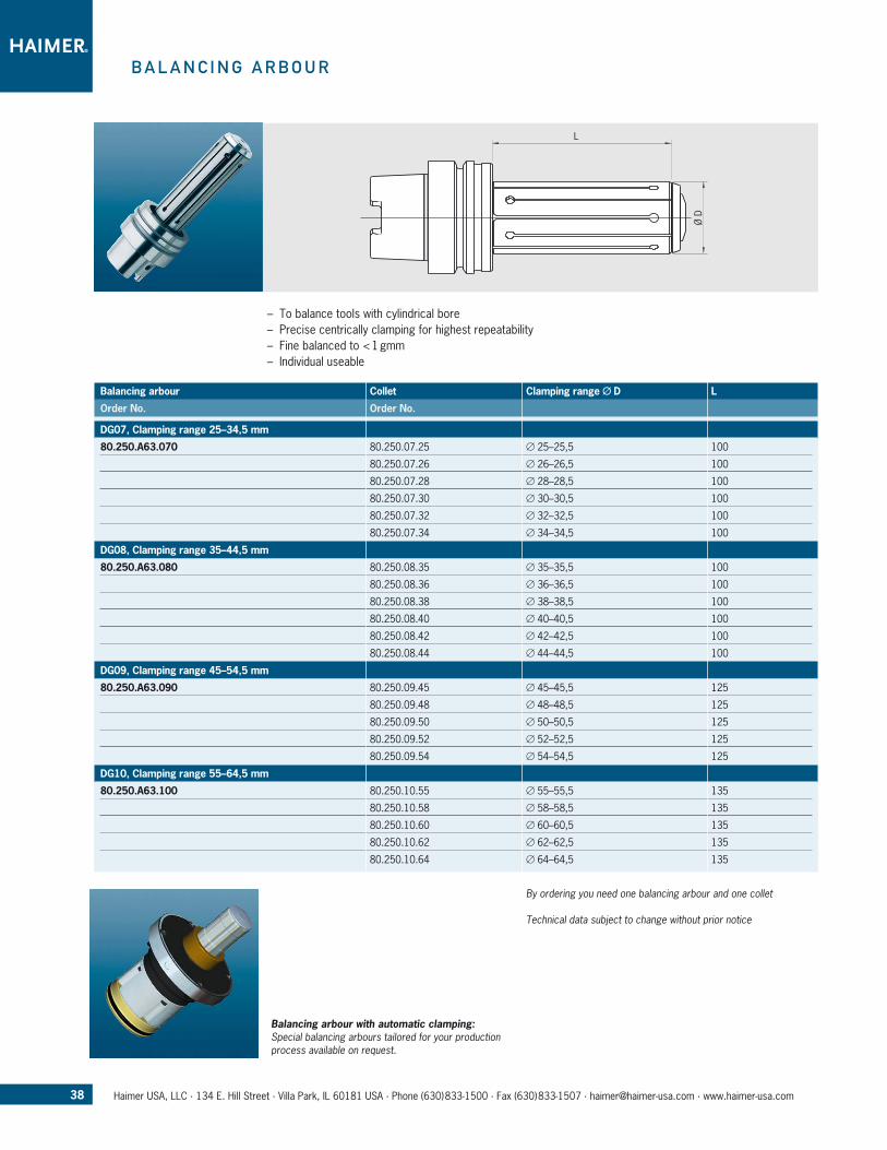
B a l a n C i n G a r B o u r
– To balance tools with cylindrical bore – Precise centrically clamping for highest repeatability – Fine balanced to < 1 gmm – Individual useable
Balancing arbour Collet Clamping range Ø D L
Order No. Order No.
DG07, Clamping range 25–34,5 mm
80.250.A63.070 80.250.07.25 Ø 25–25,5 100
80.250.07.26 Ø 26–26,5 100
80.250.07.28 Ø 28–28,5 100
80.250.07.30 Ø 30–30,5 100
80.250.07.32 Ø 32–32,5 100
80.250.07.34 Ø 34–34,5 100
DG08, Clamping range 35–44,5 mm
80.250.A63.080 80.250.08.35 Ø 35–35,5 100
80.250.08.36 Ø 36–36,5 100
80.250.08.38 Ø 38–38,5 100
80.250.08.40 Ø 40–40,5 100
80.250.08.42 Ø 42–42,5 100
80.250.08.44 Ø 44–44,5 100
DG09, Clamping range 45–54,5 mm
80.250.A63.090 80.250.09.45 Ø 45–45,5 125
80.250.09.48 Ø 48–48,5 125
80.250.09.50 Ø 50–50,5 125
80.250.09.52 Ø 52–52,5 125
80.250.09.54 Ø 54–54,5 125
DG10, Clamping range 55–64,5 mm
80.250.A63.100 80.250.10.55 Ø 55–55,5 135
80.250.10.58 Ø 58–58,5 135
80.250.10.60 Ø 60–60,5 135
80.250.10.62 Ø 62–62,5 135
80.250.10.64 Ø 64–64,5 135
By ordering you need one balancing arbour and one collet
Technical data subject to change without prior notice
Balancing arbour with automatic clamping: Special balancing arbours tailored for your production process available on request.
39Haimer USA, LLC · 134 E. Hill Street · Villa Park, IL 60181 USA · Phone (630)833-1500 · Fax (630)833-1507 · [email protected] · www.haimer-usa.com
5 m
m
M4
7 mm
+0.
14+
0.10
Ø A
54
° 2 mm
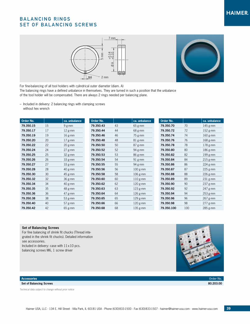
B a l a n C i n G r i n G SS e T o f B a l a n C i n G S C r e W S
For fine-balancing of all tool holders with cylindrical outer diameter (diam. A)The balancing rings have a defined unbalance in themselves. They are turned in such a position that the unbalance of the tool holder will be compensated. There are always 2 rings needed per balancing plane.
– Included in delivery: 2 balancing rings with clamping screws without hex wrench
Order No. ca. unbalance
79.350.15 15 9 g·mm
79.350.17 17 12 g·mm
79.350.19 19 16 g·mm
79.350.20 20 17 g·mm
79.350.22 22 20 g·mm
79.350.24 24 27 g·mm
79.350.25 25 32 g·mm
79.350.26 26 33 g·mm
79.350.27 27 33 g·mm
79.350.28 28 40 g·mm
79.350.30 30 45 g·mm
79.350.32 32 36 g·mm
79.350.34 34 40 g·mm
79.350.35 35 48 g·mm
79.350.36 36 47 g·mm
79.350.38 38 53 g·mm
79.350.40 40 57 g·mm
79.350.42 42 65 g·mm
Order No. ca. unbalance
79.350.43 43 65 g·mm
79.350.44 44 68 g·mm
79.350.46 46 75 g·mm
79.350.48 48 81 g·mm
79.350.50 50 87 g·mm
79.350.52 52 94 g·mm
79.350.53 53 86 g·mm
79.350.54 54 91 g·mm
79.350.55 55 94 g·mm
79.350.56 56 100 g·mm
79.350.58 58 106 g·mm
79.350.60 60 110 g·mm
79.350.62 62 120 g·mm
79.350.63 63 123 g·mm
79.350.64 64 126 g·mm
79.350.65 65 129 g·mm
79.350.66 66 120 g·mm
79.350.68 68 135 g·mm
Order No. ca. unbalance
79.350.70 70 145 g·mm
79.350.72 72 152 g·mm
79.350.74 74 160 g·mm
79.350.76 76 168 g·mm
79.350.78 78 178 g·mm
79.350.80 80 186 g·mm
79.350.82 82 199 g·mm
79.350.84 84 215 g·mm
79.350.86 86 224 g·mm
79.350.87 87 225 g·mm
79.350.88 88 226 g·mm
79.350.89 89 231 g·mm
79.350.90 90 237 g·mm
79.350.92 92 247 g·mm
79.350.94 94 253 g·mm
79.350.96 96 267 g·mm
79.350.98 98 277 g·mm
79.350.100 100 285 g·mm
Technical data subject to change without prior notice
Set of Balancing ScrewsFor fine balancing of shrink fit chucks (Thread inte-grated in the shrink fit chucks). Detailed information see accessories. Included in delivery: case with 11 x 10 pcs. balancing screws M6, 1 screw driver
Accessories Order No.
Set of Balancing Screws 80.203.00
Haimer USA, LLC · 134 E. Hill Street · Villa Park, IL 60181 USA · Phone (630)833-1500 · Fax (630)833-1507 · [email protected] · www.haimer-usa.com 4.
Editi
on ·
Prin
ted
in U
nite
d St
ates
on
100%
chl
orin
e-fre
e bl
each
ed p
aper
· 51
1 US
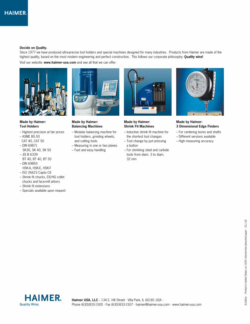
Decide on Quality. Since 1977 we have produced ultra-precise tool holders and special machines designed for many industries. Products from Haimer are made of the highest quality, based on the most modern engineering and perfect construction. This follows our corporate philosophy: Quality wins!
Visit our website: www.haimer-usa.com and see all that we can offer.
Made by Haimer: Balancing Machines
– Modular balancing machine for tool holders, grinding wheels, and cutting tools
– Measuring in one or two planes– Fast and easy handling
Made by Haimer: Shrink Fit Machines
– Inductive shrink fit machine for the shortest tool changes
– Tool change by just pressing a button
– For shrinking steel and carbide tools from diam. 3 to diam. 32 mm
Made by Haimer: 3 Dimensional Edge Finders
– For centering bores and shafts– Different versions available– High measuring accuracy
Made by Haimer: Tool Holders
– Highest precision at fair prices– ASME B5.50 CAT 40, CAT 50– DIN 69871 SK30, SK 40, SK 50– JIS B 6339 BT 40, BT 40, BT 50– DIN 69893 HSK-A, HSK-E, HSK-F– ISO 26623 Capto C6– Shrink fit chucks, ER/HG collet
chucks and face-mill arbors– Shrink fit extensions– Specials available upon request