Embed Size (px)
Citation preview

1
Karnaugh MapsWith
A Brief History of Logic Design
by
Jon T. ButlerNaval Postgraduate School
Monterey, CA U.S.A.KIT Special Lecture - June 22, 2010 - J. T. Butler

2KIT Special Lecture - June 22, 2010 - J. T. Butler
You are here
I live here

3KIT Special Lecture - June 22, 2010 - J. T. Butler
Monterey

4KIT Special Lecture - June 22, 2010 - J. T. Butler

5KIT Special Lecture - June 22, 2010 - J. T. Butler
Governor Arnold
Schwarzenegger
Actor Clint Eastwood
Actor James Dean

6KIT Special Lecture - June 22, 2010 - J. T. Butler

7
A Brief History of Logic Design
KIT Special Lecture - June 22, 2010 - J. T. Butler

8
Functions of a Logic VariableMuch of what we study here dates back to the work of George Boole (1815-1864), who established the mathematics of logic in An investigation of the laws of thought published in 1854. Boole died in 1864after walking from home to schoolin the rain and lecturing in wet clothes. He was 49 years old. Boole’s work was not used until Charles S. Peirce (1839-1914) who was the first to consider itsapplication to electronic circuits.
From http://en.wikipedia. org/wiki/George_Boole
KIT Special Lecture - June 22, 2010 - J. T. Butler

9
Functions of a Logic VariableClaude E. Shannon (1916 - 2001) was born in Petoskey, Michigan. His father was a businessman and his mother was a language teacher. He graduated in 1940 from MIT with a Master’s degree in electrical engineering and a Ph.D. degree in mathematics. His Master’s thesis was A Symbolic Analysisof Relay and Switching Circuits.This was based on Boole’s theoryand laid the foundation forswitching theory used in today’scomputers.
From http://en.wikipedia. org/wiki/Claude_Shannon
KIT Special Lecture - June 22, 2010 - J. T. Butler
10
Functions of a Logic Variable1932: Entered Univ. of Michigan at 16.
1936: Graduated from Univ. of Michigan with an EE and a Math. undergraduate degree at 20.
1937: Completed masters thesis on switching theory at 21.
1938: Published “A symbolicanalysis of relay and switchingcircuits” in AIEE Transactions at 22.
Later, Shannon established information theory. From http://en.wikipedia.
org/wiki/Claude_Shannon
10KIT Special Lecture - June 22, 2010 - J. T. Butler

11
Functions of a Logic VariableBecause they were used for telephone exchanges and for motor control, Shannon studied two-terminal switching circuits, like that shown below
a bS T
Is this series connection more like
1. AND (S T) or2. OR (S + T) ?
11KIT Special Lecture - June 22, 2010 - J. T. Butler

12
Functions of a Logic VariableIt depends whether you focus on the
conditions when 1. a is connected to b or 2. a is not connected to b.
If you focus on the conditions when a is connected to b, then this occurs when S AND T are connected.
If you focus on the conditions when a is not connected to b, then this occurs when S OR T are not connected. Shannon adopted this viewpoint.
a bS T
12KIT Special Lecture - June 22, 2010 - J. T. Butler
13
Functions of a Logic Variable
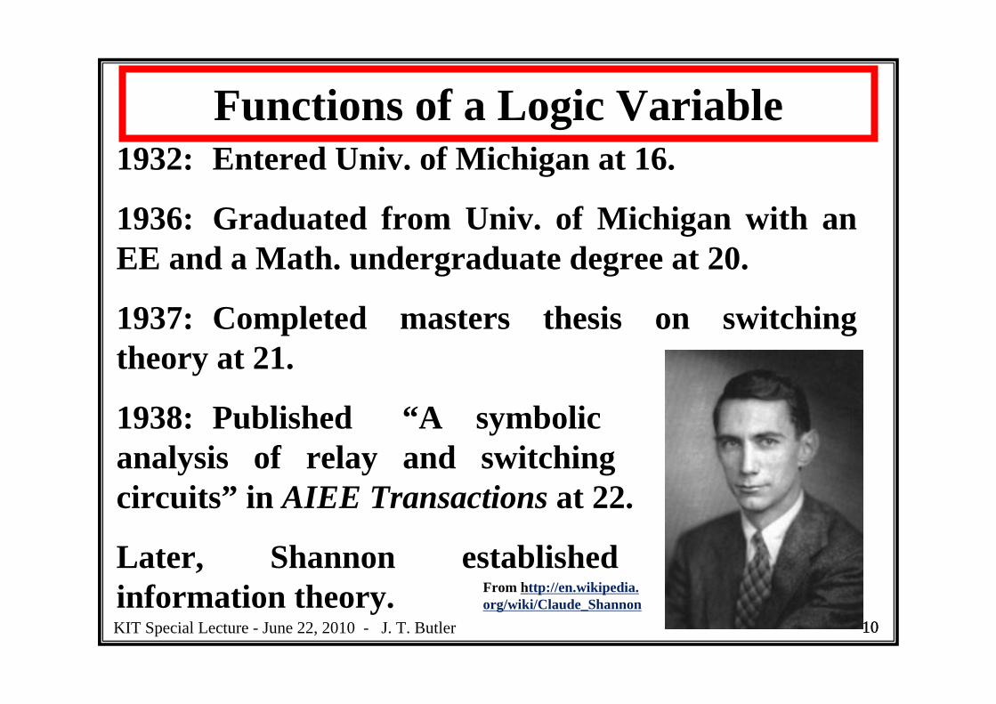
It is interesting that the foundation of computing lies on the theory of two-terminal circuits that are nowadays very old technology
a bS T
However, there is a surprise. Shannon was not the first to establish switching theory.
13KIT Special Lecture - June 22, 2010 - J. T. Butler

14
Functions of a Logic VariableAkira Nakashima of NEC published a series of papers on switching theory between 1934 and 1938 all of which were before Shannon’s publications.
Nakashima was born in 1908 and graduated from University of Tokyo in 1930 at 22. At NEC, he initially worked on switching circuits, but in 1936 at 26 was transferred to the transmission engineering group. However, he
From Akihiko Yamada. 14KIT Special Lecture - June 22, 2010 - J. T. Butler
15
Functions of a Logic Variable
continued to work on switching theory at night. Nakashima’s contributions continued until 1941. Later, Nakashima served as managing director of NEC and was appointed president of Ando Electric Co. in 1965 until be died in 1970 at 62 [1].
Nakashima’s writings are considered difficult to read (even for Japanese*). On the other hand, Shannon was considered to be a lucid writer.* The Japanese written language changed considerably.
15KIT Special Lecture - June 22, 2010 - J. T. Butler

16
Functions of a Logic Variable
16KIT Special Lecture - June 22, 2010 - J. T. Butler

17
Functions of a Logic Variable
This table is from [1].17KIT Special Lecture - June 22, 2010 - J. T. Butler

18
Functions of a Logic VariableThere are five known statues of Shannon – 1. Univ. of Michigan, 2. MIT, 3. Gaylord, MI, 4. AT&T Bell Labs, and 5. U.C.-San Diego.
[1] A. Yamada, “History of research on switching theory in Japan – On the contributions of Akira Nakashima,” Proceedings of the Reed-Muller Workshop 2009, Naha, Okinawa, May 23-24, 2009, pp. 1-7.
From http://www.eecs.umich.edu/shannonstatue/
18KIT Special Lecture - June 22, 2010 - J. T. Butler

19
Karnaugh Maps
KIT Special Lecture - June 22, 2010 - J. T. Butler

20
Minimizing Logic Circuits
GOAL: Find the minimal realization of the function
A B C f(A,B,C)
0 0 0 00 0 1 00 1 0 00 1 1 01 0 0 01 0 1 01 1 0 11 1 1 1
ABC
ABC
KIT Special Lecture - June 22, 2010 - J. T. Butler

21
Minimizing Logic Circuits (cont’d)
Algebraic Solution:Write a canonical sum-of-products expression
Apply distributivity
Apply and
Needs one 2-input AND gate.
, ,f A B C ABC ABC
, ,f A B C AB C C
, ,f A B C AB
1C C 1AB AB
OR
KIT Special Lecture - June 22, 2010 - J. T. Butler

22
Minimizing Logic Circuits (cont’d)
GOAL: Find the AND-OR two-level minimal realization of the function (Find the minimum SOP.)
A B C f(A,B,C)
0 0 0 00 0 1 00 1 0 00 1 1 01 0 0 01 0 1 01 1 0 11 1 1 1
AB
ABC 00 01 11 10
0
0
0
0
0
0
1
1
1
0
Karnaugh Map
Reflected Gray Code
KIT Special Lecture - June 22, 2010 - J. T. Butler

23
Minimizing Logic Circuits (cont’d)
Karnaugh Map Solution:
Circle the two adjacent pair of 1’s and write thecorresponding expression
, ,f A B C AB
KIT Special Lecture - June 22, 2010 - J. T. Butler

24
Karnaugh Maps are an easy way to
do algebraKIT Special Lecture - June 22, 2010 - J. T. Butler

25
Minimizing Logic Circuits (cont’d)
Karnaugh Maps were developed by Maurice Karnaugh, a Bell Laboratories engineer in 1953 and presented as
Maurice Karnaugh, “The map method for synthesis of combinational logic circuits,”Transactions of the American Institute of Electrical Engineers, 72, 1, 593-599, November, 1953
KIT Special Lecture - June 22, 2010 - J. T. Butler

26
Maurice Karnaugh
In 1992, he published “Generalized quicksearch for expert systems” in Proc. Artificial Intelligence for applications, pp. 30-34, 1992.
KIT Special Lecture - June 22, 2010 - J. T. Butler
Maurice Karnaugh was born on October 24, 1924 in New York City. He studied mathematics and physics at City College of New York (1944-1948) . He transferred to Yale University and received his B.Sc. Degree in 1949, M.Sc. in 1950, and his Ph.D. in physics in 1952 (in magnetic resonance)

27
Minimizing Logic Circuits (cont’d)
GOAL: Find the AND-OR two-level minimal realization of the function
A B C f(A,B,C)
0 0 0 00 0 1 00 1 0 00 1 1 01 0 0 01 0 1 11 1 0 11 1 1 1
ABCABC
ABC
KIT Special Lecture - June 22, 2010 - J. T. Butler

28
Minimizing Logic Circuits (cont’d)
Algebraic Solution:Write a canonical sum-of-products expression
Apply
Apply distributivity
, ,f A B C ABC ABC ABC
, ,f A B C ABC ABC ABC ABC
, ,f A B C B B AC AB C C
Apply and
, ,f A B C AC AB
ABC ABC ABC
1A C AC1B B
KIT Special Lecture - June 22, 2010 - J. T. Butler

29
Minimizing Logic Circuits (cont’d)
GOAL: Find the AND-OR two-level minimal realization of the function
A B C f(A,B,C)
0 0 0 00 0 1 00 1 0 00 1 1 01 0 0 01 0 1 11 1 0 11 1 1 1
AB
ABC 00 01 11 10
0
0
0
0
1
0
1
1
1
0
AC
KIT Special Lecture - June 22, 2010 - J. T. Butler

30
Minimizing Logic Circuits (cont’d)
Karnaugh Map Solution:
Circle the two adjacent pairs of 1’s and write thecorresponding expression
, ,f A B C AB AC
KIT Special Lecture - June 22, 2010 - J. T. Butler

31
Karnaugh Maps are an easy way to
do algebraKIT Special Lecture - June 22, 2010 - J. T. Butler

32
Minimizing Logic Circuits (cont’d)
Minimal AND-OR two-level circuits are not necessarily minimal. Consider
, ,f A B C AB AC
which can be realized as
AB
C
f(A, B, C)
KIT Special Lecture - June 22, 2010 - J. T. Butler
33
Minimizing Logic Circuits (cont’d)
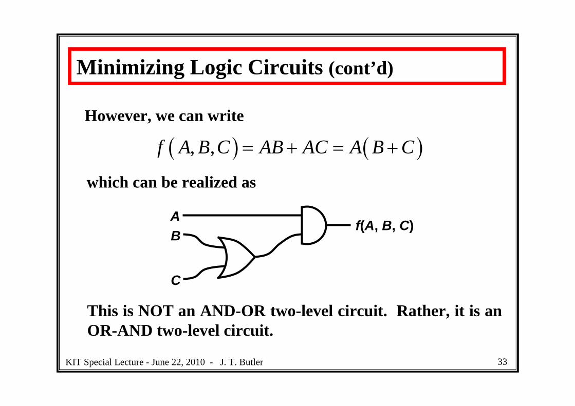
However, we can write
, ,f A B C AB AC A B C
which can be realized as
This is NOT an AND-OR two-level circuit. Rather, it is an OR-AND two-level circuit.
AB
C
f(A, B, C)
KIT Special Lecture - June 22, 2010 - J. T. Butler

34
Other CombinationsFrom previous slides, a pair of 1’s yields a single productterm. However, other combinations are possible.
AB AB A
ABC 00 01 11 10
0
0
0
0
1
1
1
1
1
0
ABC 00 01 11 10
0
0
0
0
1
1
1
1
1
0
ABC 00 01 11 10
1
0
1
0
1
0
1
0
1
0
AC AC C
ABC 00 01 11 10
1
0
1
0
1
0
1
0
1
0
KIT Special Lecture - June 22, 2010 - J. T. Butler

35
A “Look-See” Proof of Consensus
AB BC AC AC BC
ABC 00 01 11 10
0
1
0
0
1
1
1
0
1
ABC 00 01 11 10
0
1
0
0
1
1
1
0
1
00
Use the Karnaugh Map to prove a result stated previously. This is called “consensus”.
KIT Special Lecture - June 22, 2010 - J. T. Butler

36
Other Examples
, ,f A B C BC AC
ABC 00 01 11 10
1
1
1
1
0
0
0
1
1
ABC 00 01 11 10
1
0
0
0
1
0
1
0 00
, ,f A B C A BC
1
KIT Special Lecture - June 22, 2010 - J. T. Butler

37
Other Examples (cont’d)
, ,f A B C BC AB AC
ABC 00 01 11 10
0
1
1
1
1
1
1
0
1
ABC 00 01 11 10
0
1
1
1
1
1
1
0 00
, ,f A B C AC BC AB
1
KIT Special Lecture - June 22, 2010 - J. T. Butler

38
Procedure for Karnaugh Map Circling
1. Start by covering single 1 cells that cannot combine with any other 1 cell. Circle 1 cells that can combine in only one way with one other 1 cell. Continue: circle 1’s that combine uniquely in a group of 4, 8, 16, etc.
2. A minimal expression is obtained as a collection of 1’s that are as large as possible and as few as possible, so that every 1 cell is covered.
KIT Special Lecture - June 22, 2010 - J. T. Butler

39
Four-Variable Karnaugh Map
, , ,f A B C D ABCD AD
BC CD
ABCD 00 01
1
0
0
0
0
1
0
100
01
0 0
1 1
1 1
11
11
10
11 10
, , ,f A B C D ABC ACD
ABC ACD
ABCD 00 01
1
0
1
0
0
0
1
100
01
0 1
1 0
1 1
00
11
10
11 10
KIT Special Lecture - June 22, 2010 - J. T. Butler

40
Four-Variable Karnaugh Map (cont’d)
, , ,f A B C D ACD BCD
ACD BCD
ABCD 00 01
0
0
1
0
0
1
1
100
01
0 1
1 1
0 1
00
11
10
11 10
KIT Special Lecture - June 22, 2010 - J. T. Butler
41
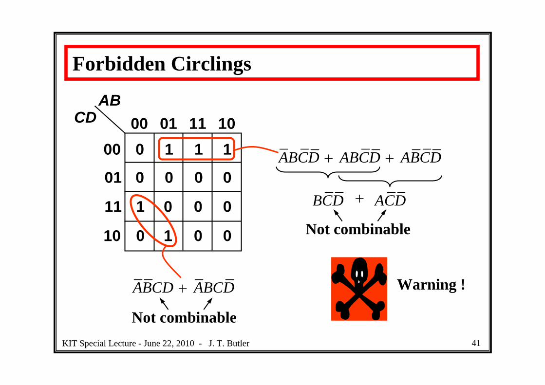
Forbidden Circlings
ABCD ABCD ABCD
ABCD ABCD
BCD ACD
Not combinable
Not combinable
ABCD 00 01
0
0
0
1
0
1
0
100
01
1 0
1 0
0 0
00
11
10
11 10
Warning !
KIT Special Lecture - June 22, 2010 - J. T. Butler

42
Acceptable Circlings
1 11
1111
1 1 1 11 1
1 11 11 11 1
1 11 1
1 1 1 11 1 1 1
KIT Special Lecture - June 22, 2010 - J. T. Butler

43
Five-Variable Karnaugh Map
, , , ,f A B C D E ABCE BCDE BCDE ACDE
ABCDE
00
01
11
10
000 001
0
1
1
0
0
0
0
0
0 0
0 0
0 0
11
011 010 110 111
0
0
0
0
0
0
1
0
0 0
1 1
0 0
01
101 100
Reflected Gray Code
KIT Special Lecture - June 22, 2010 - J. T. Butler

44
Five-Variable Karnaugh Map
, , , ,f A B C D E AD ABC ABCDE BCD BCDE
ABCD 00 01
0
1 10
01
1
00
010
1
11
0
1
0
011
10
11 10
This pair of 1’s CANNOT becombined.
111
1
1
0
0
0
00
0
00
1
1
00
00
E
Warning !
KIT Special Lecture - June 22, 2010 - J. T. Butler

45
Six-Variable Karnaugh Map
, , , , ,f A B C D E F AE BCDEF DE ABCD ABCDE ABCDF
ABCDE
00
01
11
10
000 001
0
1
0
1
0
1
0
1
0 0
1 1
0 0
11
011 010 110 111
0
1
1
1
0
1
1
1
0 01
10
0 01
101 1001
0F
0
0 0
1 1111 1 11
1
1
1 1 1 1 0000
0 0 0 0
000000
0
KIT Special Lecture - June 22, 2010 - J. T. Butler

46
Don’t Care ValuesDon’t care values result when certain assignments of values to variables never occur. For example,
The designer can expect that the assignments ABCD = 1010, 1011, …, 1111 will never occur. Thus, S1, S2, …, and S7 take on don’t care values for these assignments.
A
B
C
S1
S2
S3
S4
S5
S6
S7
D
7 SegmentDriverBCD
KIT Special Lecture - June 22, 2010 - J. T. Butler

47
Minimizing an Expression with Don’t Cares
Two Approaches
1. Find the minimal circuit for each assignment of values to the don’t cares (choose each don’t care as 0 or 1). If there are k don’t cares, there are 2k
functions (not practical for large k).
2. Enter don’t cares into Karnaugh Map and select the fewest largest circles.
KIT Special Lecture - June 22, 2010 - J. T. Butler
48
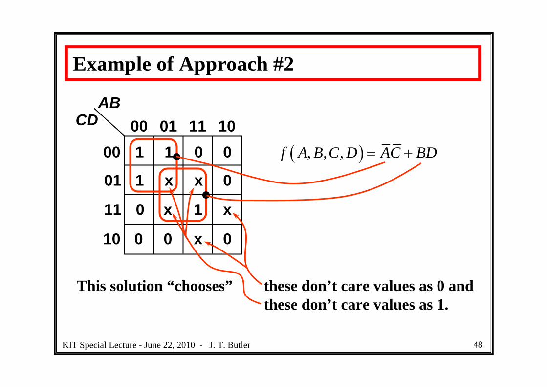
Example of Approach #2
, , ,f A B C D AC BD
ABCD 00 01
1
1
x
1
0
0
x
000
01
0 x
0 x
x 1
00
11
10
11 10
This solution “chooses” these don’t care values as 0 andthese don’t care values as 1.
KIT Special Lecture - June 22, 2010 - J. T. Butler
49
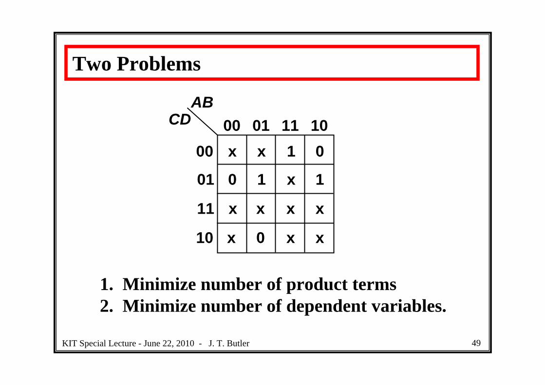
Two Problems
ABCD 00 01
0
x
1
x
1
0
x
100
01
x x
0 x
x x
xx
11
10
11 10
1. Minimize number of product terms2. Minimize number of dependent variables.
KIT Special Lecture - June 22, 2010 - J. T. Butler

50
ABCD 00 01
0
x
1
x
1
0
x
100
01
x x
0 x
x x
xx
11
10
11 10
( , , , )f A B C D BC AD
Minimize number of product terms
KIT Special Lecture - June 22, 2010 - J. T. Butler

51
Minimize number of dependent variables
ABCD 00 01
0
x
1
x
1
0
x
100
01
x x
0 x
x x
xx
11
10
11 10
( , , , )f A B C D AB BD AD
Independent of C.
KIT Special Lecture - June 22, 2010 - J. T. Butler
52
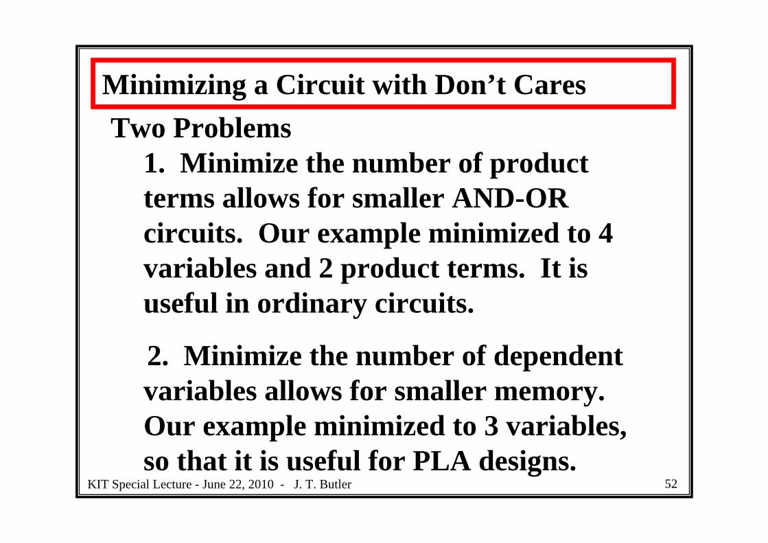
Minimizing a Circuit with Don’t CaresTwo Problems
1. Minimize the number of product terms allows for smaller AND-OR circuits. Our example minimized to 4 variables and 2 product terms. It is useful in ordinary circuits.
2. Minimize the number of dependent variables allows for smaller memory. Our example minimized to 3 variables, so that it is useful for PLA designs.
KIT Special Lecture - June 22, 2010 - J. T. Butler
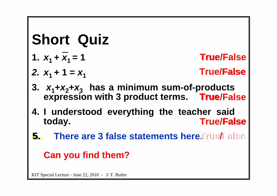
Short Quiz1. x1 + x1 = 12. x1 + 1 = x1
3. x1+x2+x3 has a minimum sum-of-products expression with 3 product terms.
4. I understood everything the teacher said today.
5. There are 3 false statements here.
Can you find them?
5.. True/False
True/False
True/False
FalseTrue/False
True/FalseTrue
5 True
True
5.. FalseFalse
KIT Special Lecture - June 22, 2010 - J. T. Butler

True/FalseShort Quiz1. This statement is false.
KIT Special Lecture - June 22, 2010 - J. T. Butler
KIT Special Lecture - June 22, 2010 - J. T. Butler