Embed Size (px)
Citation preview


Hasanoglan Cement
Fan Technology
Germany, 2009
Training course
KHD Humboldt Wedag GmbH
Wednesday, January 21, 2009 3
Table of contents� General information/introduction
� Design of fans
� Impeller design
� Comparison of different control systems
� Assembly / erection
� Commissioning
� Operation
� Executed fans
� Investigation of gas flow in a high pressure fan
KHD Humboldt Wedag GmbH
Wednesday, January 21, 2009 4
General information / introduction
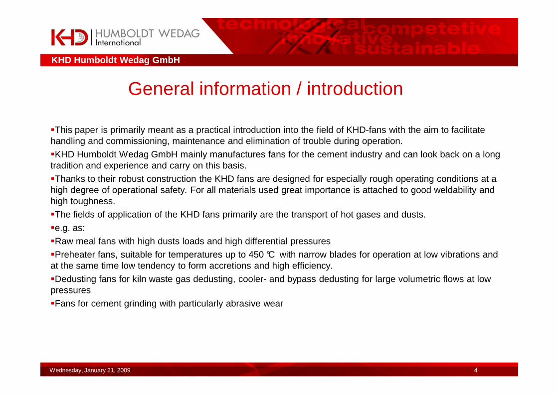
�This paper is primarily meant as a practical introduction into the field of KHD-fans with the aim to facilitate handling and commissioning, maintenance and elimination of trouble during operation.
�KHD Humboldt Wedag GmbH mainly manufactures fans for the cement industry and can look back on a long tradition and experience and carry on this basis.
�Thanks to their robust construction the KHD fans are designed for especially rough operating conditions at a high degree of operational safety. For all materials used great importance is attached to good weldability and high toughness.
�The fields of application of the KHD fans primarily are the transport of hot gases and dusts.
�e.g. as:
�Raw meal fans with high dusts loads and high differential pressures
�Preheater fans, suitable for temperatures up to 450 °C with narrow blades for operation at low vibrations and at the same time low tendency to form accretions and high efficiency.
�Dedusting fans for kiln waste gas dedusting, cooler- and bypass dedusting for large volumetric flows at low pressures
�Fans for cement grinding with particularly abrasive wear
KHD Humboldt Wedag GmbH
Wednesday, January 21, 2009 5
KHD Humboldt Wedag GmbH
Wednesday, January 21, 2009 6
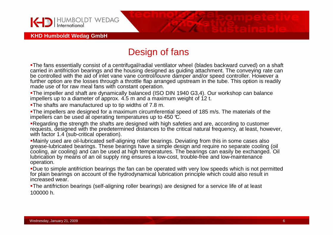
Design of fans�The fans essentially consist of a centrifugal/radial ventilator wheel (blades backward curved) on a shaft carried in antifriction bearings and the housing designed as guiding attachment. The conveying rate can be controlled with the aid of inlet vane vane control/louvre damper and/or speed controller. However a further option are the losses through a throttle flap arranged upstream in the tube. This option is readily made use of for raw meal fans with constant operation.�The impeller and shaft are dynamically balanced (ISO DIN 1940 G3,4). Our workshop can balance impellers up to a diameter of approx. 4.5 m and a maximum weight of 12 t.�The shafts are manufactured up to tip widths of 7.8 m.�The impellers are designed for a maximum circumferential speed of 185 m/s. The materials of the impellers can be used at operating temperatures up to 450 °C.�Regarding the strength the shafts are designed with high safeties and are, according to customer requests, designed with the predetermined distances to the critical natural frequency, at least, however, with factor 1.4 (sub-critical operation).�Mainly used are oil-lubricated self-aligning roller bearings. Deviating from this in some cases also grease-lubricated bearings. These bearings have a simple design and require no separate cooling (oil cooling, air cooling) and can be used at high temperatures. The bearings can easily be exchanged. Oil lubrication by means of an oil supply ring ensures a low-cost, trouble-free and low-maintenance operation.�Due to simple antifriction bearings the fan can be operated with very low speeds which is not permitted for plain bearings on account of the hydrodynamical lubrication principle which could also result in increased wear.�The antifriction bearings (self-aligning roller bearings) are designed for a service life of at least 100000 h.
KHD Humboldt Wedag GmbH
Wednesday, January 21, 2009 7
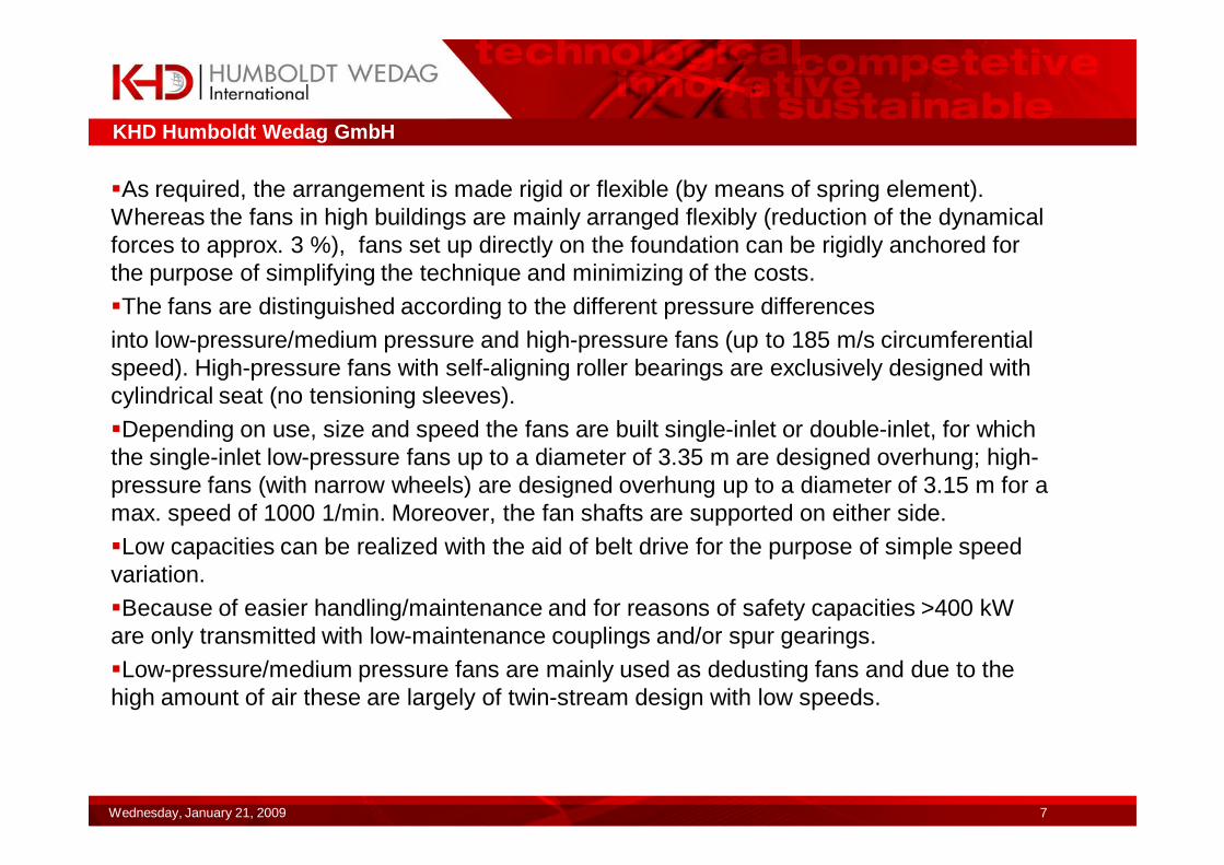
�As required, the arrangement is made rigid or flexible (by means of spring element). Whereas the fans in high buildings are mainly arranged flexibly (reduction of the dynamical forces to approx. 3 %), fans set up directly on the foundation can be rigidly anchored for the purpose of simplifying the technique and minimizing of the costs.�The fans are distinguished according to the different pressure differencesinto low-pressure/medium pressure and high-pressure fans (up to 185 m/s circumferential speed). High-pressure fans with self-aligning roller bearings are exclusively designed with cylindrical seat (no tensioning sleeves).�Depending on use, size and speed the fans are built single-inlet or double-inlet, for which the single-inlet low-pressure fans up to a diameter of 3.35 m are designed overhung; high-pressure fans (with narrow wheels) are designed overhung up to a diameter of 3.15 m for a max. speed of 1000 1/min. Moreover, the fan shafts are supported on either side.�Low capacities can be realized with the aid of belt drive for the purpose of simple speed variation.�Because of easier handling/maintenance and for reasons of safety capacities >400 kW are only transmitted with low-maintenance couplings and/or spur gearings.�Low-pressure/medium pressure fans are mainly used as dedusting fans and due to the high amount of air these are largely of twin-stream design with low speeds.
KHD Humboldt Wedag GmbH
Wednesday, January 21, 2009 8
�Advantage of single-inlet type: low cost, utilization of tumbling effect (Koriolis force) only one inlet�Advantage of double-inlet type: high air capacity at low density, lower circumferential speed of the impeller than in case of an equivalent single-inlet impeller.�Lower axial forces. Lower motor costs.�The kiln- and cooler dedusting fans are of double-inlet type on account of the high amount of air.�The classifier fan (cement grinding) is of single-inlet and overhung type due to the high wear which ensures that the fan shaft is not exposed to wear caused by the material. By ample dimensioning of the impeller , wear at the armoured impeller is low and has an long service life also in case of increased dust.
�Given below is a short survey of the fans presently taken into operation and those which will be taken into operation.
KHD Humboldt Wedag GmbH
Wednesday, January 21, 2009 9
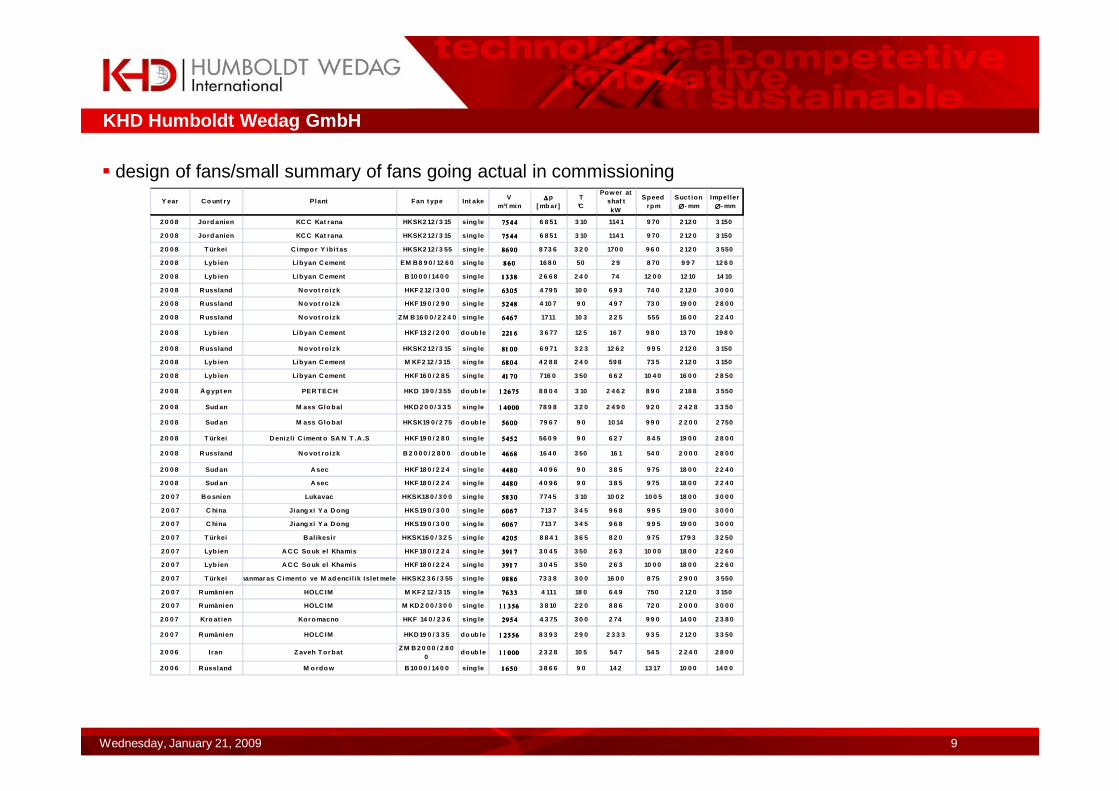
� design of fans/small summary of fans going actual in commissioningY ear C o unt ry Plant Fan t ype Int ake
Vm³/ min
∆∆∆∆p [ mb ar]
T°C
Pow er at shaf tkW
Speedrpm
Suct ion∅∅∅∅- mm
Impel ler∅∅∅∅- mm
2 0 0 8 Jord anien KC C Kat rana HKSK2 12 / 3 15 sing le 7544754475447544 6 8 51 3 10 114 1 9 70 2 12 0 3 150
2 0 0 8 Jord anien KC C Kat rana HKSK2 12 / 3 15 sing le 7544754475447544 6 8 51 3 10 114 1 9 70 2 12 0 3 150
2 0 0 8 T ürkei C impo r Y ib i t as HKSK2 12 / 3 55 sing le 8690869086908690 8 73 6 3 2 0 170 0 9 6 0 2 12 0 3 550
2 0 0 8 Lyb ien Libyan C ement EM B 8 9 0 / 12 6 0 sing le 860860860860 16 8 0 50 2 9 8 70 9 9 7 12 6 0
2 0 0 8 Lyb ien Libyan C ement B 10 0 0 / 14 0 0 sing le 1338133813381338 2 6 6 8 2 4 0 74 12 0 0 12 10 14 10
2 0 0 8 R ussland N o vot ro izk HKF 2 12 / 3 0 0 sing le 6305630563056305 4 79 5 10 0 6 9 3 74 0 2 12 0 3 0 0 0
2 0 0 8 R ussland N o vot ro izk HKF 19 0 / 2 9 0 sing le 5248524852485248 4 10 7 9 0 4 9 7 73 0 19 0 0 2 8 0 0
2 0 0 8 R ussland N o vot ro izk ZM B 16 0 0 / 2 2 4 0 sing le 6467646764676467 1711 10 3 2 2 5 555 16 0 0 2 2 4 0
2 0 0 8 Lyb ien Libyan C ement HKF 13 2 / 2 0 0 do ub le 2216221622162216 3 6 77 12 5 16 7 9 8 0 13 70 19 8 0
2 0 0 8 R ussland N o vot ro izk HKSK2 12 / 3 15 sing le 8100810081008100 6 9 71 3 2 3 12 6 2 9 9 5 2 12 0 3 150
2 0 0 8 Lyb ien Libyan C ement M KF2 12 / 3 15 sing le 6804680468046804 4 2 8 8 2 4 0 59 8 73 5 2 12 0 3 150
2 0 0 8 Lyb ien Libyan C ement HKF 16 0 / 2 8 5 sing le 4170417041704170 716 0 3 50 6 6 2 10 4 0 16 0 0 2 8 50
2 0 0 8 Ä g ypt en PER TEC H HKD 19 0 / 3 55 do ub le 12675126751267512675 8 8 0 4 3 10 2 4 6 2 8 9 0 2 18 8 3 550
2 0 0 8 Sud an M ass Glo bal HKD 2 0 0 / 3 3 5 sing le 14000140001400014000 78 9 8 3 2 0 2 4 9 0 9 2 0 2 4 2 8 3 3 50
2 0 0 8 Sud an M ass Glo bal HKSK19 0 / 2 75 do ub le 5600560056005600 79 6 7 9 0 10 14 9 9 0 2 2 0 0 2 750
2 0 0 8 T ürkei D eniz li C iment o SA N T .A .S HKF 19 0 / 2 8 0 sing le 5452545254525452 56 0 9 9 0 6 2 7 8 4 5 19 0 0 2 8 0 0
2 0 0 8 R ussland N o vot ro izk B 2 0 0 0 / 2 8 0 0 do ub le 4668466846684668 16 4 0 3 50 16 1 54 0 2 0 0 0 2 8 0 0
2 0 0 8 Sud an A sec HKF 18 0 / 2 2 4 sing le 4480448044804480 4 0 9 6 9 0 3 8 5 9 75 18 0 0 2 2 4 0
2 0 0 8 Sud an A sec HKF 18 0 / 2 2 4 sing le 4480448044804480 4 0 9 6 9 0 3 8 5 9 75 18 0 0 2 2 4 0
2 0 0 7 B o snien Lukavac HKSK18 0 / 3 0 0 sing le 5830583058305830 774 5 3 10 10 0 2 10 0 5 18 0 0 3 0 0 0
2 0 0 7 C hina Jiang xi Y a D ong HKS19 0 / 3 0 0 sing le 6067606760676067 713 7 3 4 5 9 6 8 9 9 5 19 0 0 3 0 0 0
2 0 0 7 C hina Jiang xi Y a D ong HKS19 0 / 3 0 0 sing le 6067606760676067 713 7 3 4 5 9 6 8 9 9 5 19 0 0 3 0 0 0
2 0 0 7 T ürkei B al ikesi r HKSK16 0 / 3 2 5 sing le 4205420542054205 8 8 4 1 3 6 5 8 2 0 9 75 179 3 3 2 50
2 0 0 7 Lyb ien A C C So uk el Khamis HKF 18 0 / 2 2 4 sing le 3917391739173917 3 0 4 5 3 50 2 6 3 10 0 0 18 0 0 2 2 6 0
2 0 0 7 Lyb ien A C C So uk el Khamis HKF 18 0 / 2 2 4 sing le 3917391739173917 3 0 4 5 3 50 2 6 3 10 0 0 18 0 0 2 2 6 0
2 0 0 7 T ürkeiKahr amanmar as C iment o ve M ad enci l ik Islet meler i A .S .HKSK2 3 6 / 3 55 sing le 9886988698869886 73 3 8 3 0 0 16 0 0 8 75 2 9 0 0 3 550
2 0 0 7 R umänien HOLC IM M KF2 12 / 3 15 sing le 7633763376337633 4 111 18 0 6 4 9 750 2 12 0 3 150
2 0 0 7 R umänien HOLC IM M KD 2 0 0 / 3 0 0 sing le 11356113561135611356 3 8 10 2 2 0 8 8 6 72 0 2 0 0 0 3 0 0 0
2 0 0 7 Kro at ien Kor omacno HKF 14 0 / 2 3 6 sing le 2954295429542954 4 3 75 3 0 0 2 74 9 9 0 14 0 0 2 3 8 0
2 0 0 7 R umänien HOLC IM HKD 19 0 / 3 3 5 do ub le 12556125561255612556 8 3 9 3 2 9 0 2 3 3 3 9 3 5 2 12 0 3 3 50
2 0 0 6 Iran Z aveh T or batZ M B 2 0 0 0 / 2 8 0
0do ub le 11000110001100011000 2 3 2 8 10 5 54 7 54 5 2 2 4 0 2 8 0 0
2 0 0 6 R ussland M o rdo w B 10 0 0 / 14 0 0 sing le 1650165016501650 3 8 6 6 9 0 14 2 13 17 10 0 0 14 0 0
KHD Humboldt Wedag GmbH
Wednesday, January 21, 2009 10
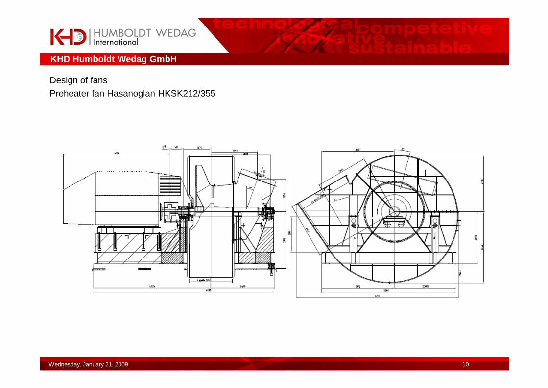
Design of fans
Preheater fan Hasanoglan HKSK212/355
KHD Humboldt Wedag GmbH
Wednesday, January 21, 2009 11
Data of performance Preheater-fan:� volume flow V: 8690 m³/min� pressure difference ∆pst: 84 mbar� pressure difference ∆pt: 87,36 mbar� temperature °C: 320°C� speed: 960 1/min� power consumption Pw: 1700 kW� motor power: 1785 kW at 330 up to 960 1/min� content of dust: 25 g/m³� density at entree: 0,519 kg/m³
� drive: coupling� control system: frequency control� installation: spring units� bearing: on both sides, pendular roller bearing� vibration control: both sides� temperature monitoring: PT100 (both sides)
KHD Humboldt Wedag GmbH
Wednesday, January 21, 2009 12
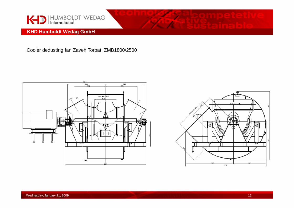
Cooler dedusting fan Zaveh Torbat ZMB1800/2500

KHD Humboldt Wedag GmbH
Wednesday, January 21, 2009 13
Datas of performance cooler dedusting-fan:� volume flow V: 9155 m³/min� pressure difference ∆pst: 20 mbar� pressure difference ∆pt: 22,53 mbar� temperature °C: 240 °C� speed: 695 1/min� power consumption Pw: 437 kW� motor power: 450 kW at 330 up to 730 1/min� content of dust: 0,05 g/m³� density at entree: 0,563 kg/m³
� drive: coupling� control: frequency control� installation: rigidly anchored� bearing: both sides, pendular roller bearing� vibration control: both sides� temperature monitoring: PT100 (both sides)
KHD Humboldt Wedag GmbH
Wednesday, January 21, 2009 14
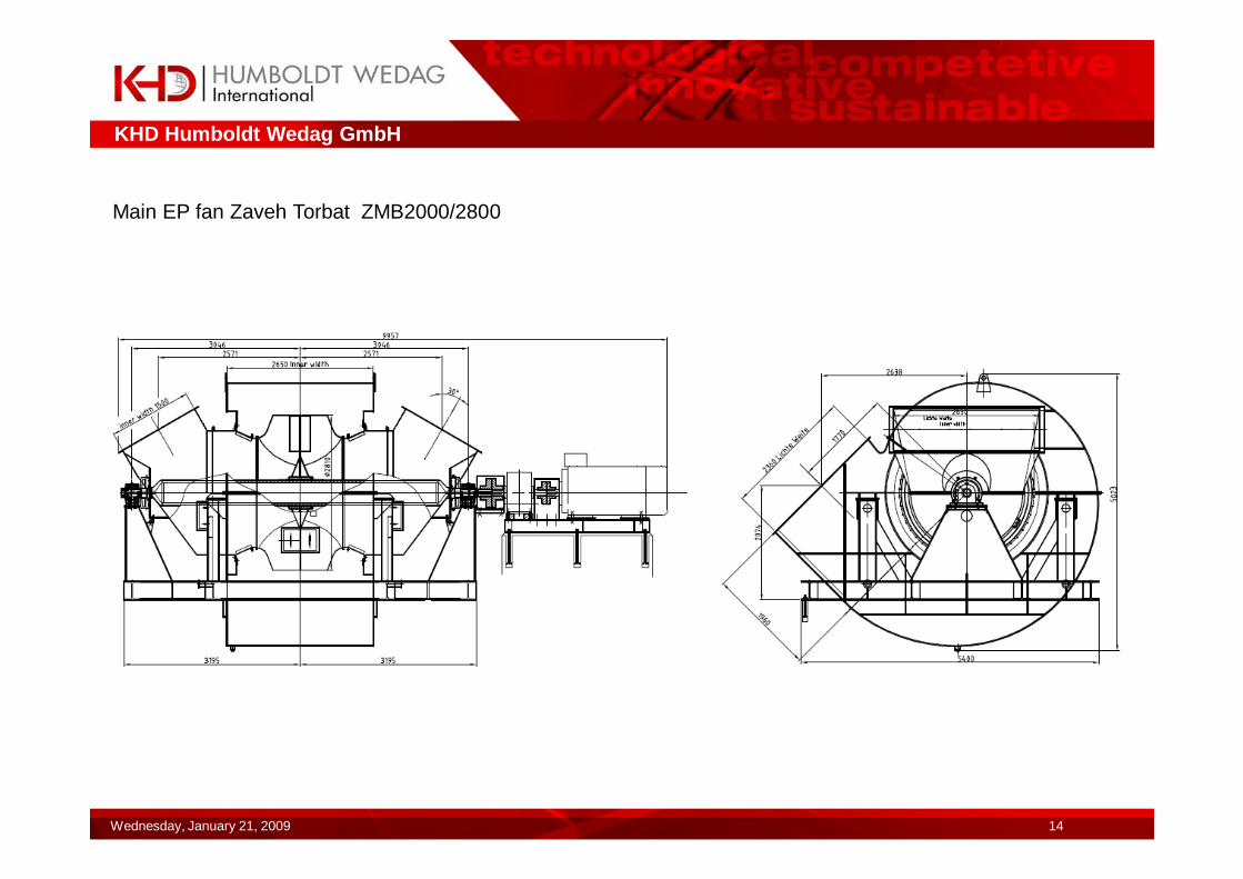
Main EP fan Zaveh Torbat ZMB2000/2800
KHD Humboldt Wedag GmbH
Wednesday, January 21, 2009 15
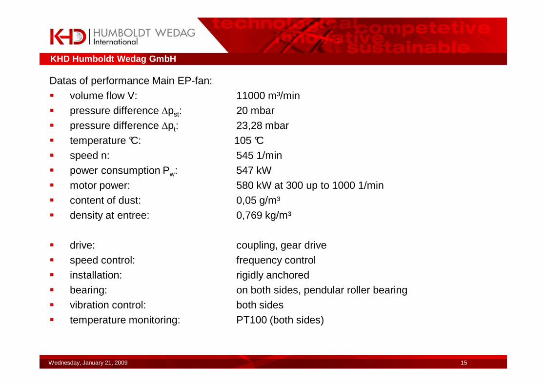
Datas of performance Main EP-fan:� volume flow V: 11000 m³/min� pressure difference ∆pst: 20 mbar� pressure difference ∆pt: 23,28 mbar� temperature °C: 105 °C� speed n: 545 1/min� power consumption Pw: 547 kW� motor power: 580 kW at 300 up to 1000 1/min� content of dust: 0,05 g/m³� density at entree: 0,769 kg/m³
� drive: coupling, gear drive� speed control: frequency control� installation: rigidly anchored� bearing: on both sides, pendular roller bearing� vibration control: both sides� temperature monitoring: PT100 (both sides)
KHD Humboldt Wedag GmbH
Wednesday, January 21, 2009 16
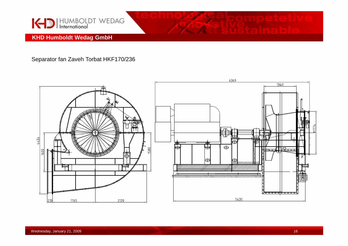
Separator fan Zaveh Torbat HKF170/236
KHD Humboldt Wedag GmbH
Wednesday, January 21, 2009 17
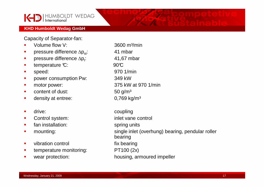
Capacity of Separator-fan:� Volume flow V: 3600 m³/min� pressure difference ∆pst: 41 mbar� pressure difference ∆pt: 41,67 mbar� temperature °C: 90°C� speed: 970 1/min� power consumption Pw: 349 kW� motor power: 375 kW at 970 1/min� content of dust: 50 g/m³� density at entree: 0,769 kg/m³
� drive: coupling� Control system: inlet vane control� fan installation: spring units� mounting: single inlet (overhung) bearing, pendular roller
bearing� vibration control fix bearing � temperature monitoring: PT100 (2x)� wear protection: housing, armoured impeller
KHD Humboldt Wedag GmbH
Wednesday, January 21, 2009 18
Design of fans / materials / shafts
•Solid shafts
Preheater-/ S355J2G3, P355NH, 13CrMo4-5Mill fans forgedSingle –stream type
�Hollow shaft/welded construktionpreheater-/ S355J2G3, P355NH, 16Mo3 Mill-/waste gas fans shaft journal forgedTwin stream type tubes seamless hot rolled (EN10210)
�All forged solid shafts and hollow shaft/tubes, journals with inspection certificate 3.1b�EN10204 and ultrasonic testing EN10246. Hollow shafts are balanced separately according to DIN 1940 G6,3.
KHD Humboldt Wedag GmbH
Wednesday, January 21, 2009 19
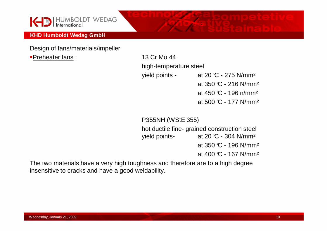
Design of fans/materials/impeller �Preheater fans : 13 Cr Mo 44
high-temperature steelyield points - at 20 °C - 275 N/mm²
at 350 °C - 216 N/mm²at 450 °C - 196 n/mm²at 500 °C - 177 N/mm²
P355NH (WStE 355)hot ductile fine- grained construction steelyield points- at 20 °C - 304 N/mm²
at 350 °C - 196 N/mm²at 400 °C - 167 N/mm²
The two materials have a very high toughness and therefore are to a high degree insensitive to cracks and have a good weldability.
KHD Humboldt Wedag GmbH
Wednesday, January 21, 2009 20
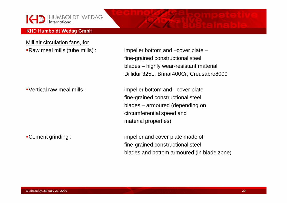
Mill air circulation fans, for �Raw meal mills (tube mills) : impeller bottom and –cover plate –
fine-grained constructional steelblades – highly wear-resistant materialDillidur 325L, Brinar400Cr, Creusabro8000
�Vertical raw meal mills : impeller bottom and –cover platefine-grained constructional steelblades – armoured (depending oncircumferential speed andmaterial properties)
�Cement grinding : impeller and cover plate made offine-grained constructional steelblades and bottom armoured (in blade zone)
KHD Humboldt Wedag GmbH
Wednesday, January 21, 2009 21
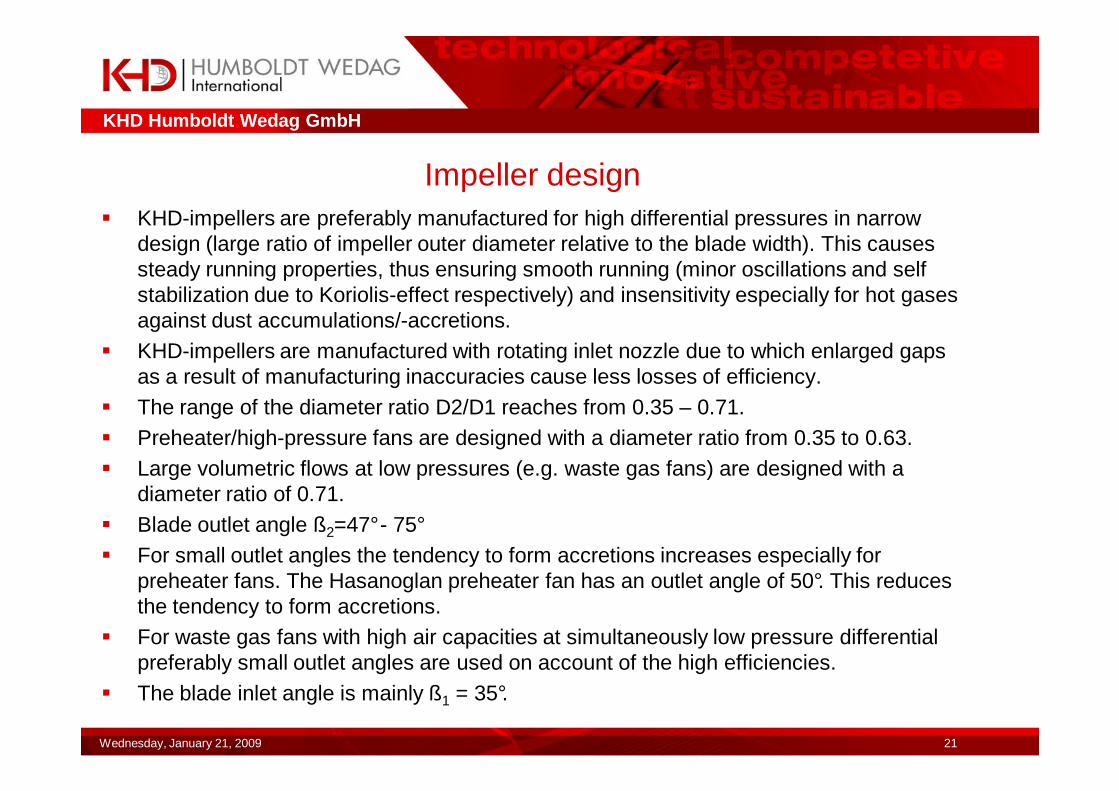
Impeller design� KHD-impellers are preferably manufactured for high differential pressures in narrow
design (large ratio of impeller outer diameter relative to the blade width). This causes steady running properties, thus ensuring smooth running (minor oscillations and self stabilization due to Koriolis-effect respectively) and insensitivity especially for hot gases against dust accumulations/-accretions.
� KHD-impellers are manufactured with rotating inlet nozzle due to which enlarged gaps as a result of manufacturing inaccuracies cause less losses of efficiency.
� The range of the diameter ratio D2/D1 reaches from 0.35 – 0.71.� Preheater/high-pressure fans are designed with a diameter ratio from 0.35 to 0.63.� Large volumetric flows at low pressures (e.g. waste gas fans) are designed with a
diameter ratio of 0.71.� Blade outlet angle ß2=47°- 75°� For small outlet angles the tendency to form accretions increases especially for
preheater fans. The Hasanoglan preheater fan has an outlet angle of 50°. This reduces the tendency to form accretions.
� For waste gas fans with high air capacities at simultaneously low pressure differential preferably small outlet angles are used on account of the high efficiencies.
� The blade inlet angle is mainly ß1 = 35°.
KHD Humboldt Wedag GmbH
Wednesday, January 21, 2009 22
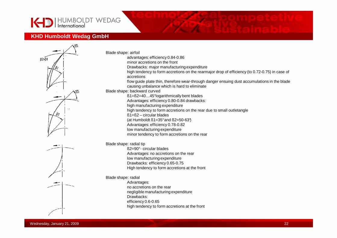
Blade shape: airfoiladvantages: efficiency 0.84-0.86minor accretions on the frontDrawbacks: major manufacturing expenditurehigh tendency to form accretions on the rearmajor drop of efficiency (to 0.72-0.75) in case of accretionsflow guide plate thin, therefore wear-through danger ensuing dust accumulations in the blade causing unbalance which is hard to eliminate
Blade shape: backward curvedß1=ß2=40…45°logarithmically bent bladesAdvantages: efficiency 0.80-0.84 drawbacks:high manufacturing expenditurehigh tendency to form accretions on the rear due to small outletangleß1=ß2 – circular blades(at Humboldt ß1=35°and ß2=50-63°)Advantages: efficiency 0.78-0.82low manufacturing expenditureminor tendency to form accretions on the rear
Blade shape: radial tipß2=90°- circular bladesAdvantages: no accretions on the rearlow manufacturing expenditureDrawbacks: efficiency 0.65-0.75High tendency to form accretions at the front
Blade shape: radialAdvantages:no accretions on the rearnegligible manufacturing expenditureDrawbacks:efficiency 0.6-0.65high tendency to form accretions at the front
KHD Humboldt Wedag GmbH
Wednesday, January 21, 2009 23
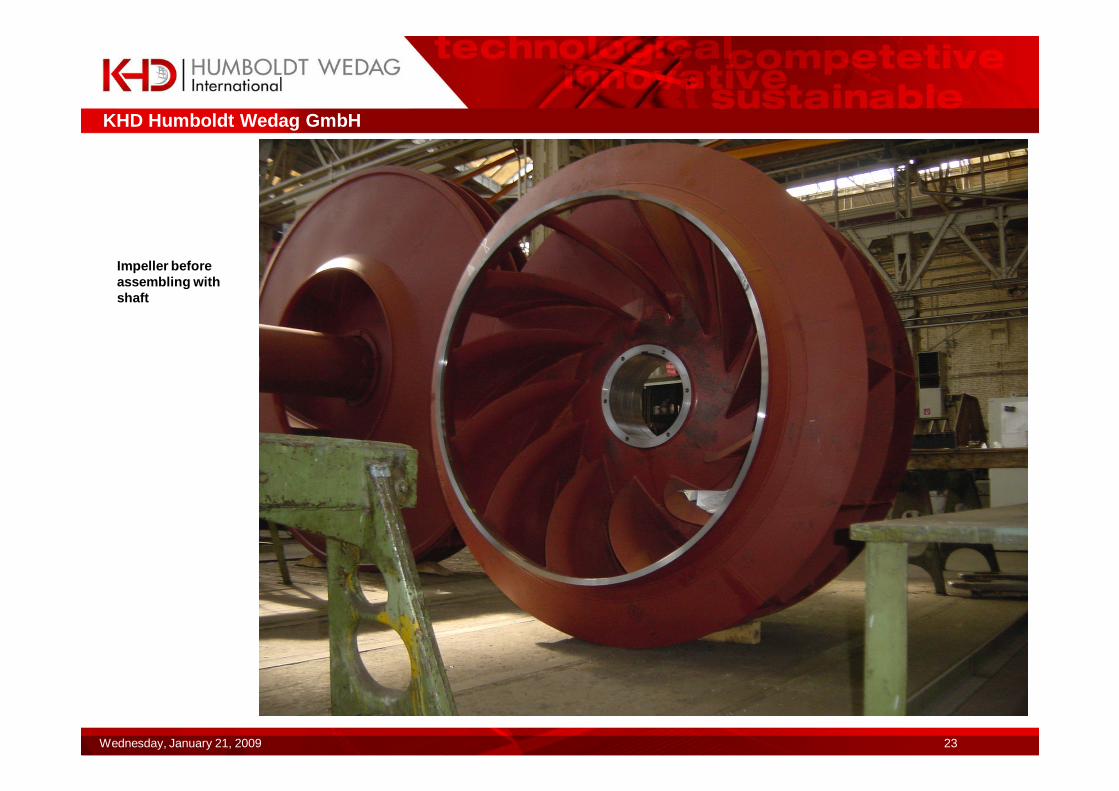
Impeller before assembling with shaft
KHD Humboldt Wedag GmbH
Wednesday, January 21, 2009 24
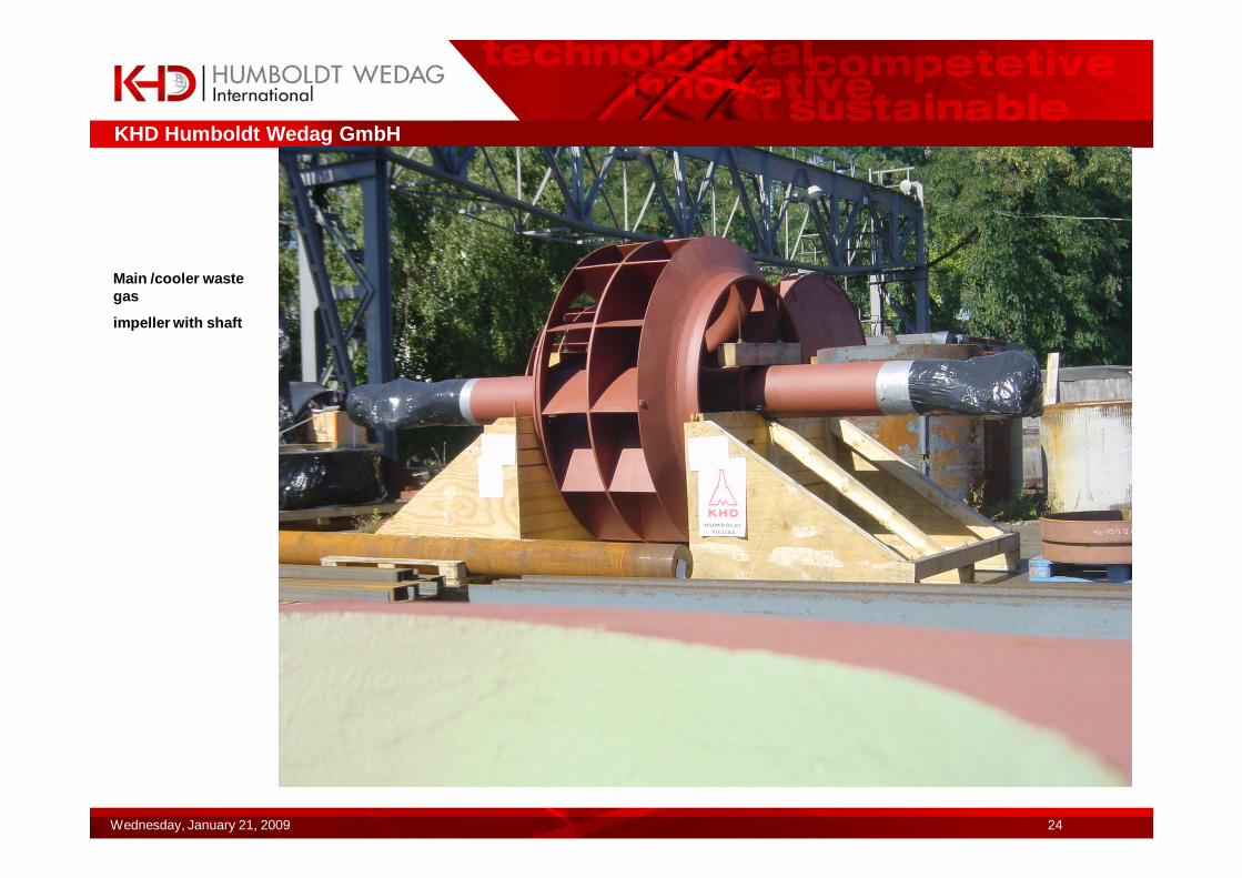
Main /cooler waste gas
impeller with shaft
KHD Humboldt Wedag GmbH
Wednesday, January 21, 2009 25
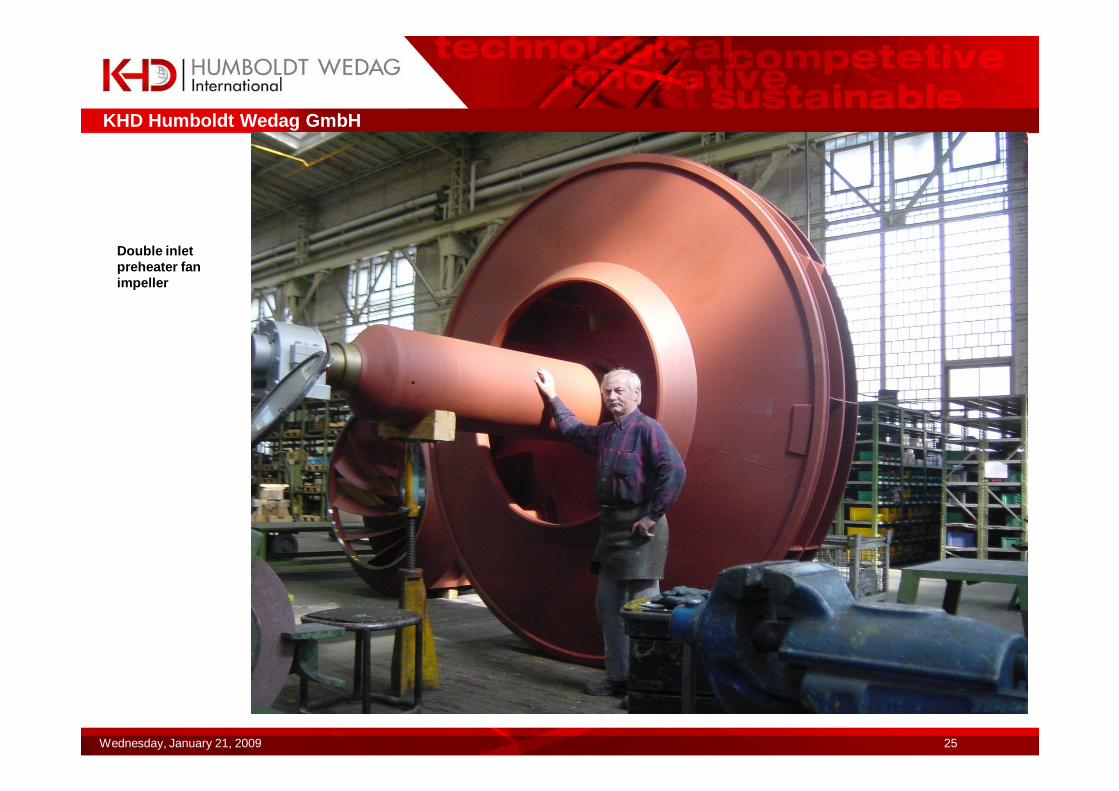
Double inlet preheater fan impeller
KHD Humboldt Wedag GmbH
Wednesday, January 21, 2009 26
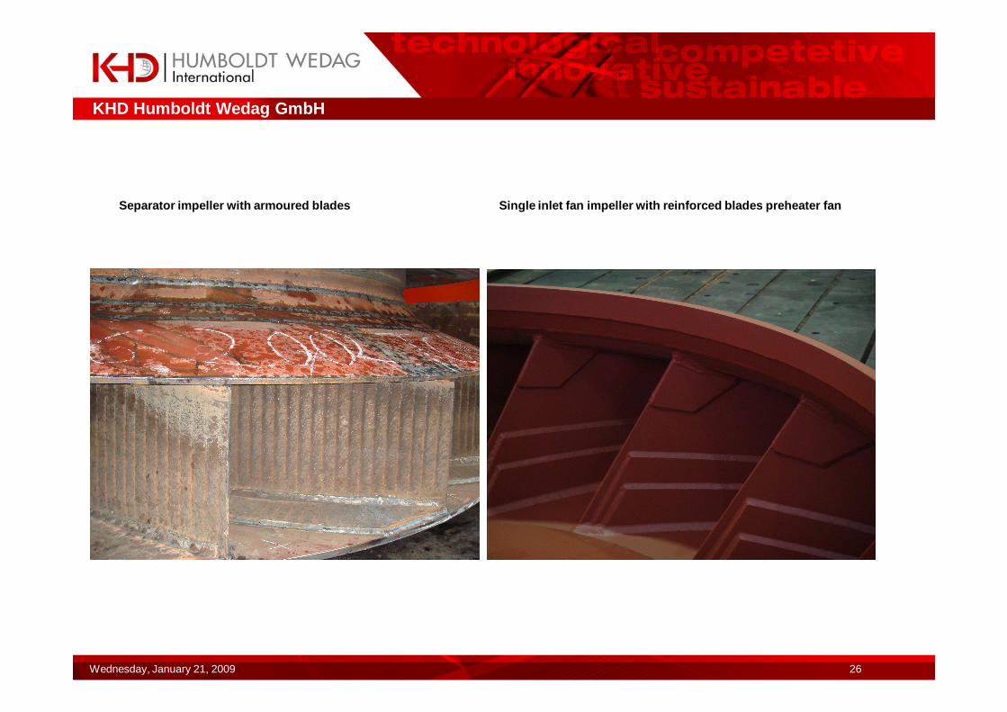
Separator impeller with armoured blades Single inlet fan impeller with reinforced blades preheater fan
KHD Humboldt Wedag GmbH
Wednesday, January 21, 2009 27
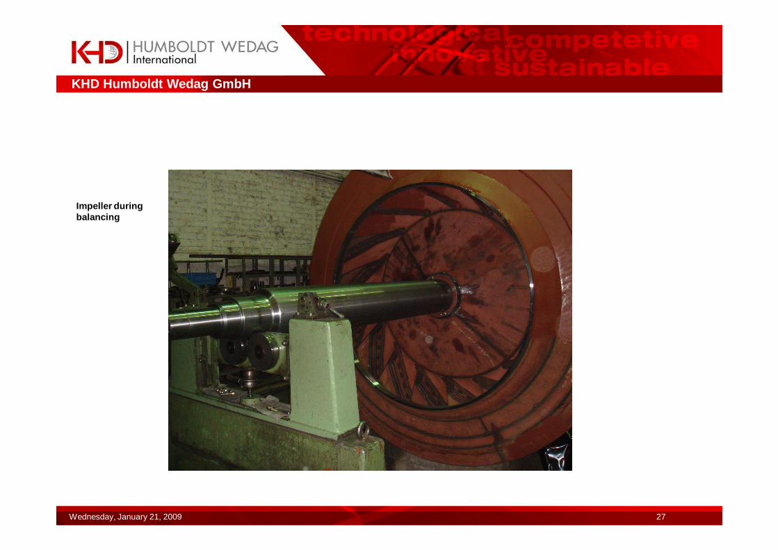
Impeller during balancing
KHD Humboldt Wedag GmbH
Wednesday, January 21, 2009 28
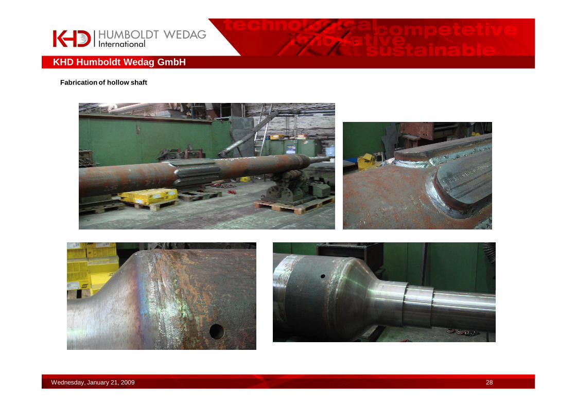
Fabrication of hollow shaft
KHD Humboldt Wedag GmbH
Wednesday, January 21, 2009 29
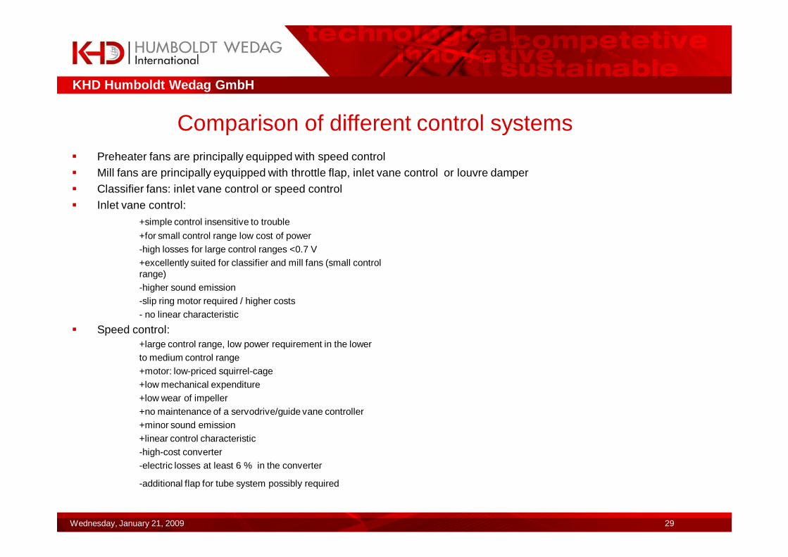
Comparison of different control systems� Preheater fans are principally equipped with speed control� Mill fans are principally eyquipped with throttle flap, inlet vane control or louvre damper� Classifier fans: inlet vane control or speed control� Inlet vane control:
+simple control insensitive to trouble
+for small control range low cost of power-high losses for large control ranges <0.7 V+excellently suited for classifier and mill fans (small control range)-higher sound emission-slip ring motor required / higher costs- no linear characteristic
� Speed control:+large control range, low power requirement in the lowerto medium control range+motor: low-priced squirrel-cage+low mechanical expenditure+low wear of impeller+no maintenance of a servodrive/guide vane controller+minor sound emission+linear control characteristic-high-cost converter-electric losses at least 6 % in the converter
-additional flap for tube system possibly required
KHD Humboldt Wedag GmbH
Wednesday, January 21, 2009 30
�Louvre damper +simple handling at maximum pressure difference and large units-higher losses than for inlet vane control at large control ratio V/Vmin+very suitable as starting aid e.g. for raw mill fans
�Throttle flap: (in tube in front of fan)+low-cost solution with minor resistance (if not throttled)+low mechanic expenditure-can result in problems when starting in the non-stable range (if no speed control is existing)+few wear parts+increased noise emission-high losses upon strong throttling by additional differential pressure
KHD Humboldt Wedag GmbH
Wednesday, January 21, 2009 31
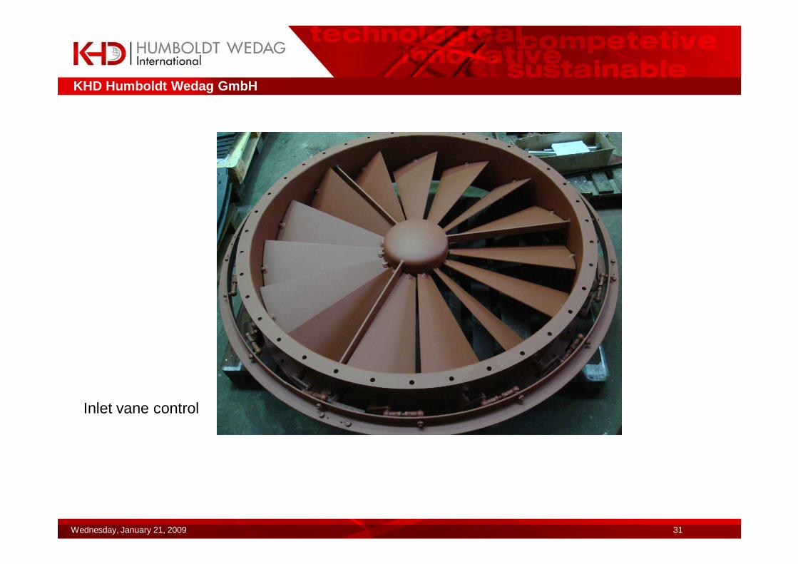
Inlet vane control
KHD Humboldt Wedag GmbH
Wednesday, January 21, 2009 32
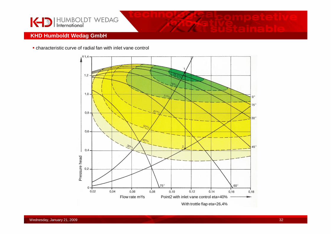
� characteristic curve of radial fan with inlet vane control
Flow rate m³/s Point2 with inlet vane control eta=40%
With trottle flap eta=26,4%
Pre
ssur
e he
ad
KHD Humboldt Wedag GmbH
Wednesday, January 21, 2009 33
soun
d in
tens
ity le
vel v
aria
tion
∆L p
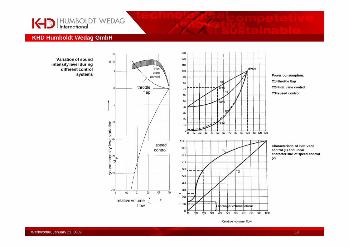
relative volume flow
inlet vane
control
throttle flap
speed control
Variation of sound intensity level during
different control systems
Relative volume flow
Power consumption:
C1=throttle flap
C2=Inlet vane control
C3=speed control
Characteristic of inlet vane control (1) and linear characteristic of speed control (2)
KHD Humboldt Wedag GmbH
Wednesday, January 21, 2009 34
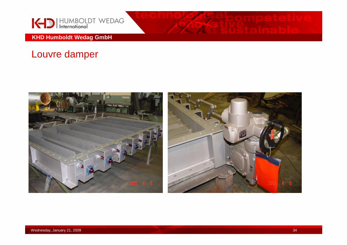
Louvre damper
KHD Humboldt Wedag GmbH
Wednesday, January 21, 2009 35
Assembly/erection
�Base frame/foundation frameBase frame (for flexible support: foundation frame) to be aligned in the plane and space (50 mm) to be grouted with fine concrete. In case of split base frame the distance of the bearing plates and recesses for the bearing plates to be welded indicated in the schedule must be kept.�Bearing platesThe bearing plates must be let into the corresponding recesses of the base frames and aligned according to the schedule. The different bearing plates shall have been aligned in the plane for which a base frame aligned in the plane is taken for granted. The deviation from parallelism of the bearing plates (towards each other) should not exceed 0.2 mm. The deviation from the plane should not exceed 0.1 mm. The upper supporting surface of the bearing plates has been machined and must not be mixed up. The aligned bearing plates must be welded to the base frame with minor distortions.�(one after the other alternately short opposite seams)�Through the weld seam in the neutral zone of the properly dimensioned bearing plates distortions are substantially excluded.
KHD Humboldt Wedag GmbH
Wednesday, January 21, 2009 36
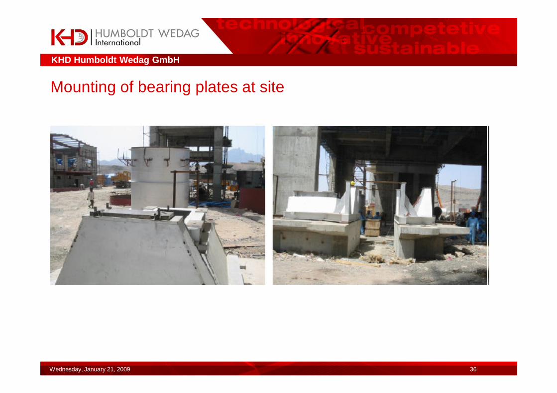
Mounting of bearing plates at site
KHD Humboldt Wedag GmbH
Wednesday, January 21, 2009 37
Assembly
�At first the bottom part of the housing and of the inlet cone are placed in the base frame and provisionally aligned.�Impeller with shaft are placed on the aligned bearing plates and screwed.�When doing so the movable bearing clearance for the expansion caused by the temperature must be observed. The bearing housings shall be installed right-angled to the shaft axis as oil leakages may occur due to non-uniform sealing gaps.�It is by no means allowed to place individual different lining plates underneath the bearing housings. This may result in distortions and/or damage to the bearing.�Now the housing top and the top of the inlet cone must be fitted and aligned relative to the shaft. The shaft seal/packing box and movable- and fixed bearing must freely rest on the shaft seats.�After alignment and screwing of the housing supports on the frame supports, the housing supports must be welded to the housing and missing reinforcements must be fitted to the housing. Afterwards the shaft seal must be checked once more.
KHD Humboldt Wedag GmbH
Wednesday, January 21, 2009 38
�Alignment of inlet cone
The nozzle of the inlet cone must be aligned and formed so that a minimum radial gap of 6 mm to the impeller is existing. The nozzle of the inlet cone should project into the impeller by 25-30 mm. Incorrect inlet cones may entail a reduced transport capacity.
�Tubes/expansion joints
All tubes must have been installed so that no forces whatsoever can act on the fan. Especially in case of flexibly supported fans all expansion joints should be freely movable.
�Spring element
The spring elements shall have been aligned so that the machine is level.
This can simply be found out by way of the spring element height which, among each other, should not deviate from each other by more than 3 mm (for spring element height, see the information given in the foundation drawing)
�The drive, coupling and the motor must be arranged precisely parallel to the axis. Angle deviations and parallel offset may entail oscillations.
�Control elements such as inlet vane controllers must have been arranged in the direction of the air flow. The correct opening direction should be verified as described below:
Inlet vane control half-opened, guide vanes of inlet vane control shall point in the direction of rotation of the housing helix growing to the housing outlet. The same principle shall also be applied for the louvre dampers, where at half-opened louvre damper the air stream shall be directed in the sense of rotation of the opening housing helix.

KHD Humboldt Wedag GmbH
Wednesday, January 21, 2009 39
Commissioning
�Prior to commissioning the movable bearing clearance specified in the documentation has to be verified by dismantling of the bearing top. The oil supply ring for oil lubrication must be loosely suspended on the shaft. The oil level of the bearing housing must be within the range of the limit values and the grease labyrinths must have been filled with grease. The bearing housings must be free from leakages.�The gap of the grease-lubricated labyrinth seal must be regular (+-0.5 mm), otherwise the bearing housing must be newly aligned. (In case of an irregular gap oil leakages may occur due the pump effect.�The bearing housings must have been directly mounted on the bearing plate. It is not permitted to use lining plates.�All bearing monitoring systems (bearing temperature and bearing oscillation) must be checked for proper functioning/interlocking (for max. temperature see the documentation oil 75 °C grease storage 65 °C)�The clearance between inlet cone and impeller must be verified as per documentation. (approx. 6 mm)�The impeller must at no point have a mechanical contact.�All fastening screws must be checked for proper tightening.�Check of direction of rotation of the impeller and inlet vane control (if any).�All expansion joints must be checked for free movability, whether no load from the tube can act upon the fan.�Check of spring elements for uniform clamping height.�Check of drive for angularity/offset and check of gap between drive and output end according to the documentation.�Check of bearing housing for angularity relative to the shaft, the sealing gap of the grease labyrinths must be uniform.�The shaft seal of the fan housing must have been freely mounted on the shaft.�Prior to commissioning it must be checked whether rain water, if any, inside the housing must be drained.�During commissioning the bearing temperature must be observed more intensely to avoid damage due to incorrect assembly (see the documentation).�Causes for increased temperatures at the bearing are less wear of the bearing but:�Lack of oil�Too small bearing clearance due the shaft expansion caused by the temperature�Distorted bearing; caused by uneven support (bearing plates)�Distinct feature: obvious in the frequency spectrum at strong sidebands beside the operating frequency.�Incorrect fitting of the oil supply ring (rigidly clamped)�Insufficient bearing clearance due to incorrect assembly on the base frame (base frame incorrectly positioned)�Clamping device not correctly mounted.�For grease storages, in most cases too much greased after topping up�Use of unsuitable grease especially upon high operating speeds the lubrication greases should not contain ageing additives which may narrow the gap (no hot bearing greases)�In case of temperature problems the bearing housings should not be cooled from outside; this additionally narrows the bearing gap.�Increased bearing temperatures caused by convection should be reduced by means of a thermal shield and and stronger cooling vane.
KHD Humboldt Wedag GmbH
Wednesday, January 21, 2009 40
Operation
�Constant, troublefree operation can only be ensured by observing the data specified in the technical documentation:�Listed below are some essential causes of trouble:�Loss of efficiency:
too large gap between inlet cone and impellerpoor intake conditions (knee/bend in tube shortly in front of suction cone)inlet not free of spinsbranching of tube shortly behind fanincorrectly designed density (incorrect height indication, operating temperature, standard density)Example Kerman Momtazan: Density at inlet 0.602 kg/m³ at altitude 0 and 0.477 kg/m³ at actual altitude 1700 m (26 % difference in the density)Moreover, an indication of an insufficient density may prompt insufficient dimensioning of the motor capactiy.This must expecially be observed for speed controls, as in this case the transformer has a higher thermal load due to the increased torque at low speed.
�Aerodynamical trouble /pumps:The fan should be operated always on the left of the summit point of its characteristic curve. During operation in the non-stable range (performance graph on the left of the summit point) oscillations caused by air pulsation may result in damage to the machine.In this case a remedy is a guide vane controller or a louvre damper.Vane-controlled machines with high speed (>1500 1/min) should be operated with slightly opened guide vane controller in the starting phase in order to avoid oscillations.
KHD Humboldt Wedag GmbH
Wednesday, January 21, 2009 41
�Increased oscillations:�Possible causes:�Unbalance due to transport damage, distortion caused by overheating, accretions, strong wear�Defective, not free, expansion joints�Loose or distorted machine parts (not adequately assembled)�Damage in impeller (for example crack in reinforcing cone)�Generally transport damage is obvious at the cover plate or at the bottom plate (caused by hard placing during reloading) and should be remedied by dynamical balancing according to DIN ISO 1940 Q6,3. Here, special attention should be focussed on the axial oscillations as this may cause cracks in the reinforcing cone of the impeller and damage to the bearing. This also applies to distorted impellers as a result of overheating especially regarding preheater fans. Worn-down impellers should be repaired in part and afterwards dynamically balanced (by KHD specialists).�Accretions and accumulations especially occur at mill fans and preheater fans on the blade rear.�For mill fans the effects of accretions can be kept low or without decisive influence as described below.�blades with outlet angle >= 47°�use of narrow blades contrary to clean gas impellers

KHD Humboldt Wedag GmbH
Wednesday, January 21, 2009 42
�Accretions in preheater fans�Partial coming-off of the accretions, when reaching a critical accretion compound major unbalance is created at the impeller, which occur as major horizontal oscillations.�Factors which influence the tendency to form accretions :�Velocity of the dust particles inside the impeller-inlet nozzle.�This velocity in inlet should be kept below 40 m/s.�Tests of several well-known fan manufacturers revealed that from 40 m/s the tendency to form accretions strongly increases.�Temperature of the medium to be conveyed�From 300 °C temperature of medium to be conveyed sligh t accretions are to be expected, for which the physical-chemical properties of the dust particles influence this temperature limit.�Above 350 °C operating temperature the tendency to fo rm accretions becomes stronger and should be minimized with the aid of narrow blades and large blade outlet angles.�Speed of fan�The speed of the preheater fans should not exceed 1000 1/min and the circumferential speed of the impeller should range below 185 m/s.�Blade shape�The blade shape influences localization of accretions at the impeller (see under Enclosure). The blades should be preferably narrow and provided with outlet angles >47°. (At Hasanoglan 50°have been realized at the preheater fan�Physical-chemical properties of the dust particles�Dust with higher clay component causes hard, layer-type accretions on the blade rear sides.�Accretions can passively be reduced by means of an acoustic horn.
KHD Humboldt Wedag GmbH
Wednesday, January 21, 2009 43
� Increased wear:Raw meal is less abrasive than cement dust, however as from a dust portion of 60 g/m² especially for roller press grinding the impeller should be armoured. If no high differential pressures (as for vertical mills) are requested, the gas velocity in the impeller inlet should be kept below 34 m/s. Wear is yet increased due to especially coarse grain size of the dusts contained in the air to be transported.
� Expansion joints:The expansion joints should have been fitted freely movable and should be free from material/accretions. No load from the weight from the tube must be introduced.
Increased oscillation through solid expansion joints (stops) are obvious from the flattening of the upper sinus oscillation in the oscillograph.
� Loose defective parts:Increased oscillations can occur loose or by incorrect placing of the bearing housings on the bearing plates. This missing stiffness is manifested by strong vertical oscillations (larger than horizontal) which have maximum amplitude for the operating frequency.
� Damage inside impeller:Increased oscillations can be caused by damage already occurred inside the impeller.
This damage can be cracks or heavily worn-down zones. Therefore, it is absolutely required that the permissible limit values are not exceeded and the machine is stopped or inspected. During operation it should always be made sure that the axial oscillations are lower than the radial oscillations, as these cause cross-oscillations in the impeller bottom.
KHD Humboldt Wedag GmbH
Wednesday, January 21, 2009 44
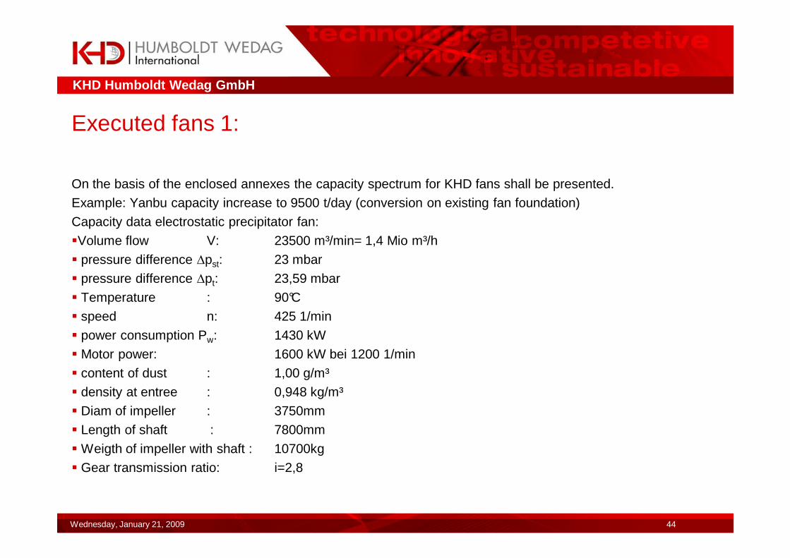
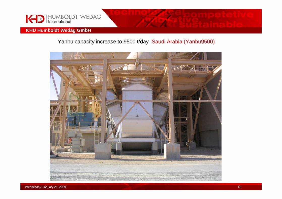
Executed fans 1:
On the basis of the enclosed annexes the capacity spectrum for KHD fans shall be presented.
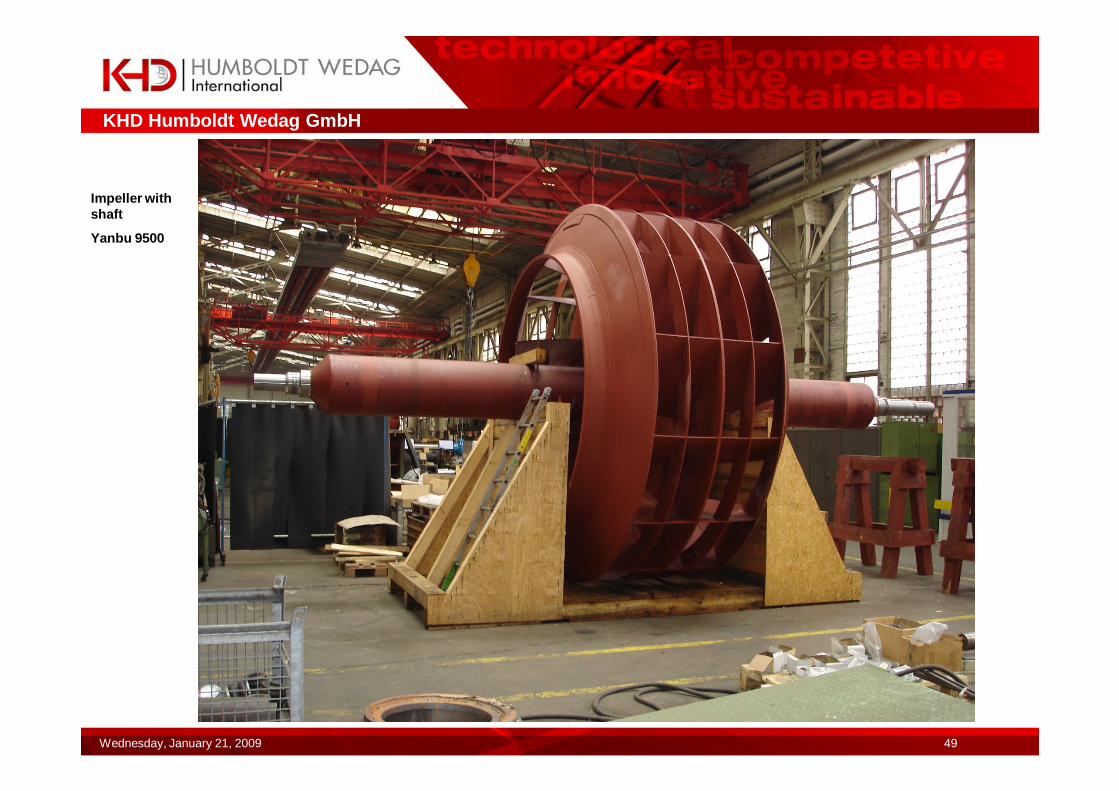
Example: Yanbu capacity increase to 9500 t/day (conversion on existing fan foundation)
Capacity data electrostatic precipitator fan:
�Volume flow V: 23500 m³/min= 1,4 Mio m³/h
� pressure difference ∆pst: 23 mbar
� pressure difference ∆pt: 23,59 mbar
� Temperature : 90°C
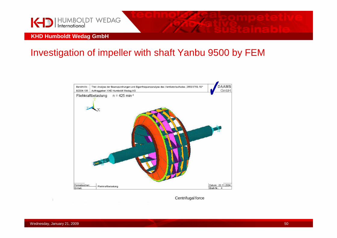
� speed n: 425 1/min
� power consumption Pw: 1430 kW
� Motor power: 1600 kW bei 1200 1/min
� content of dust : 1,00 g/m³
� density at entree : 0,948 kg/m³
� Diam of impeller : 3750mm
� Length of shaft : 7800mm
� Weigth of impeller with shaft : 10700kg
� Gear transmission ratio: i=2,8
KHD Humboldt Wedag GmbH
Wednesday, January 21, 2009 45
Yanbu capacity increase to 9500 t/day Saudi Arabia (Yanbu9500)
KHD Humboldt Wedag GmbH
Wednesday, January 21, 2009 46
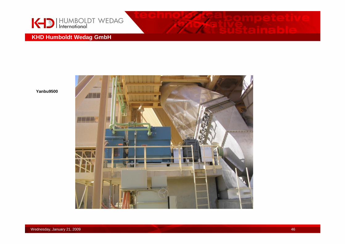
Yanbu9500
KHD Humboldt Wedag GmbH
Wednesday, January 21, 2009 47
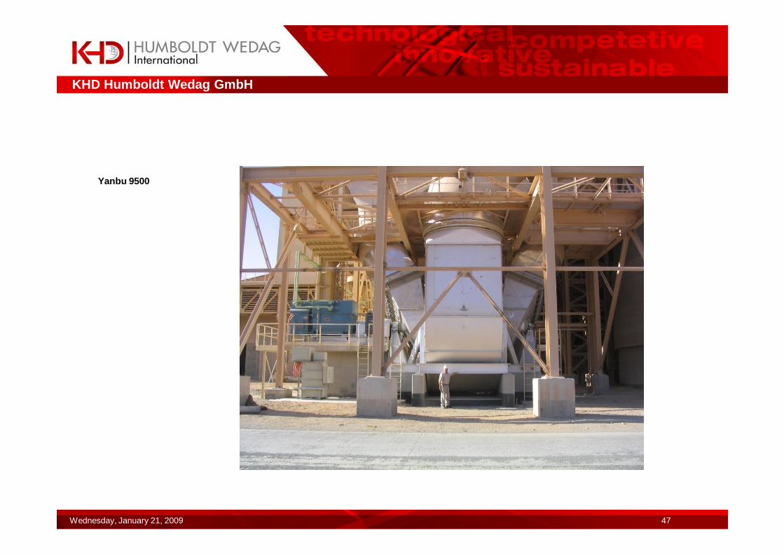
Yanbu 9500
KHD Humboldt Wedag GmbH
Wednesday, January 21, 2009 48
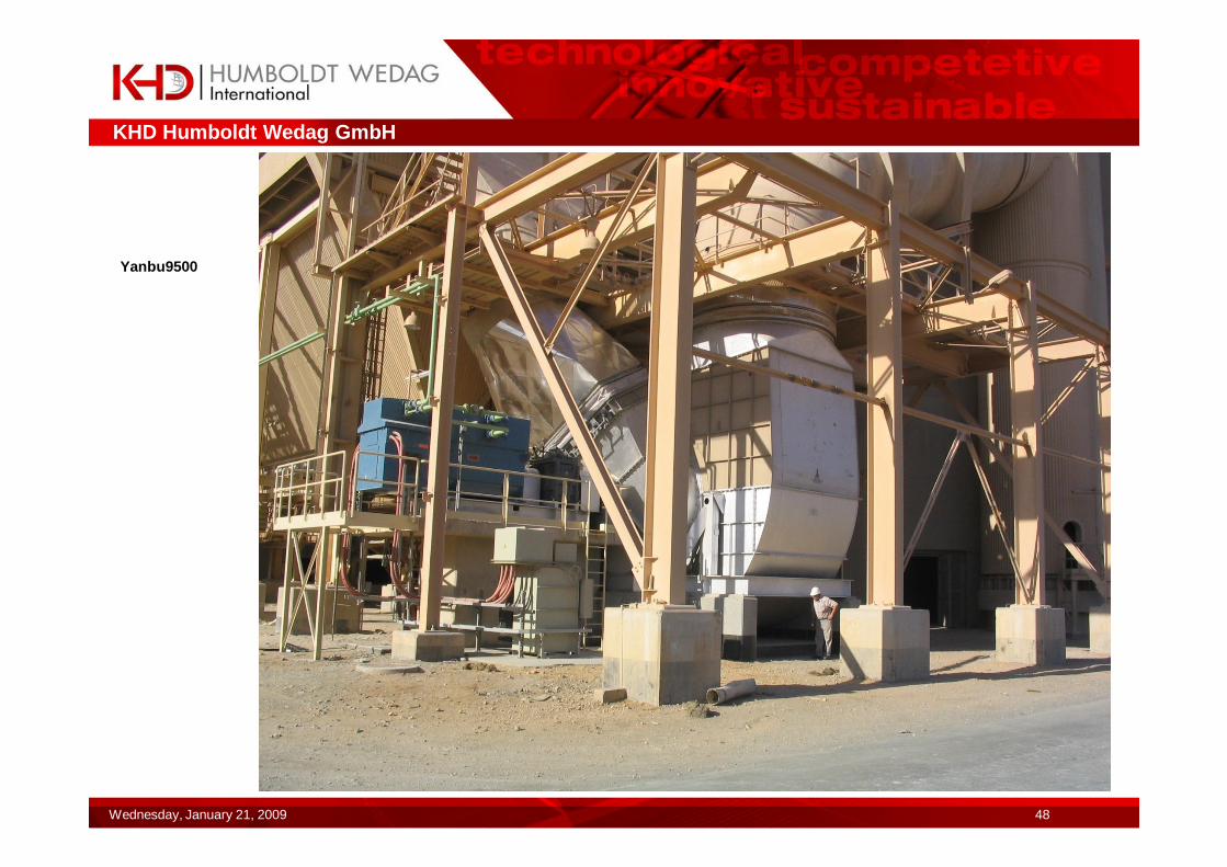
Yanbu9500
KHD Humboldt Wedag GmbH
Wednesday, January 21, 2009 49
Impeller with shaft
Yanbu 9500
KHD Humboldt Wedag GmbH
Wednesday, January 21, 2009 50
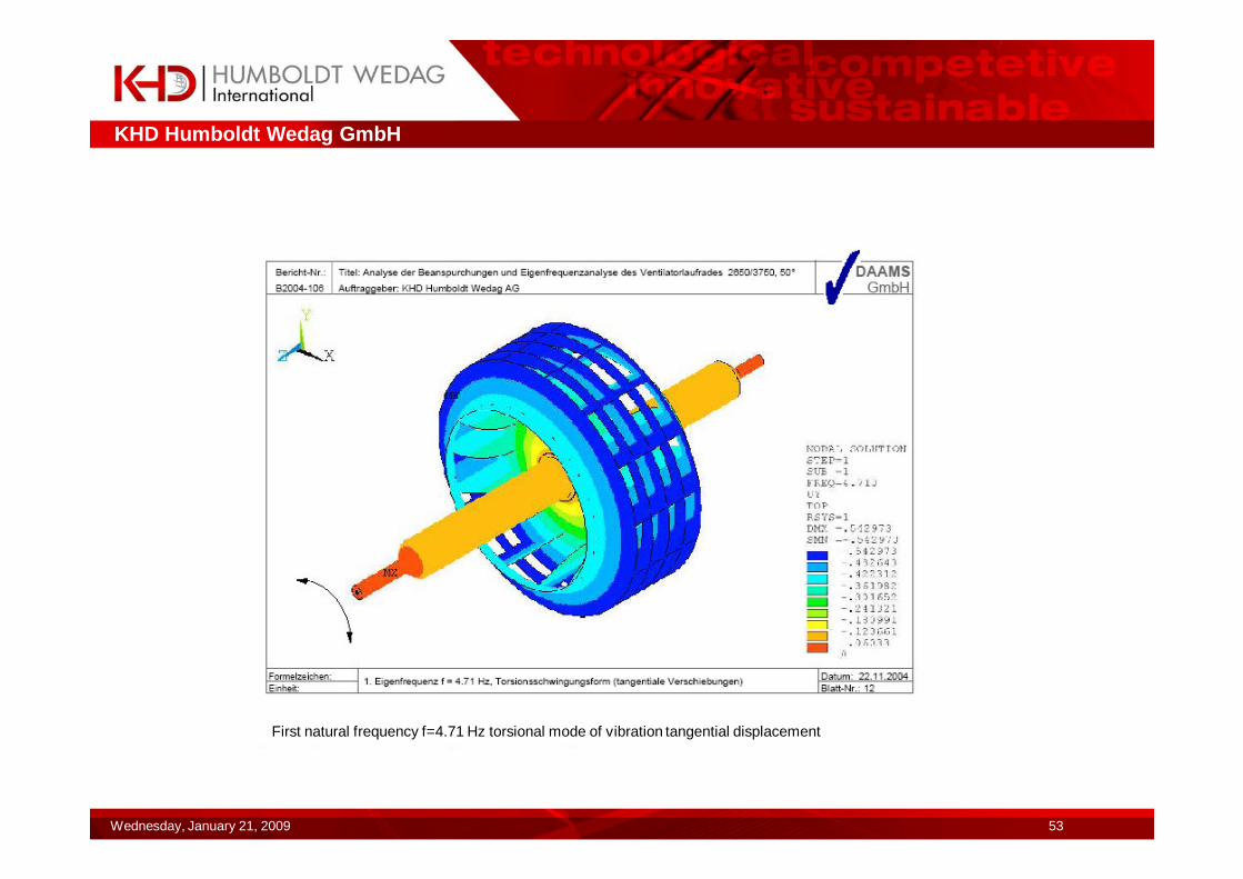
Investigation of impeller with shaft Yanbu 9500 by FEM
Centrifugal force
KHD Humboldt Wedag GmbH
Wednesday, January 21, 2009 51
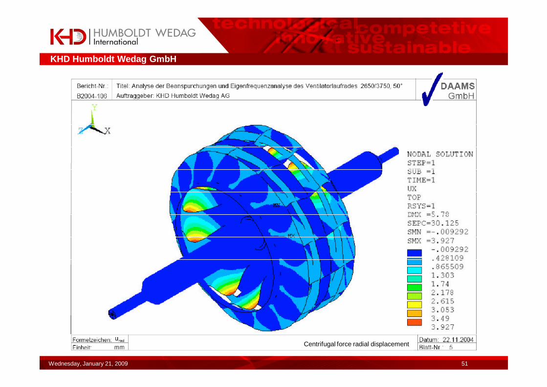
Centrifugal force radial displacement
KHD Humboldt Wedag GmbH
Wednesday, January 21, 2009 52
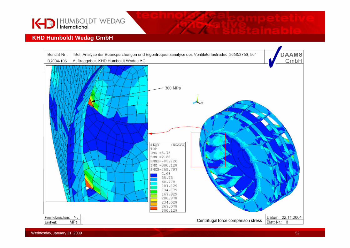
Centrifugal force comparison stress
KHD Humboldt Wedag GmbH
Wednesday, January 21, 2009 53
First natural frequency f=4.71 Hz torsional mode of vibration tangential displacement
KHD Humboldt Wedag GmbH
Wednesday, January 21, 2009 54
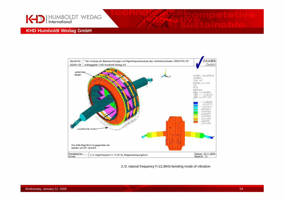
2./3. natural frequency f=13,36Hz bending mode of vibration
KHD Humboldt Wedag GmbH
Wednesday, January 21, 2009 55
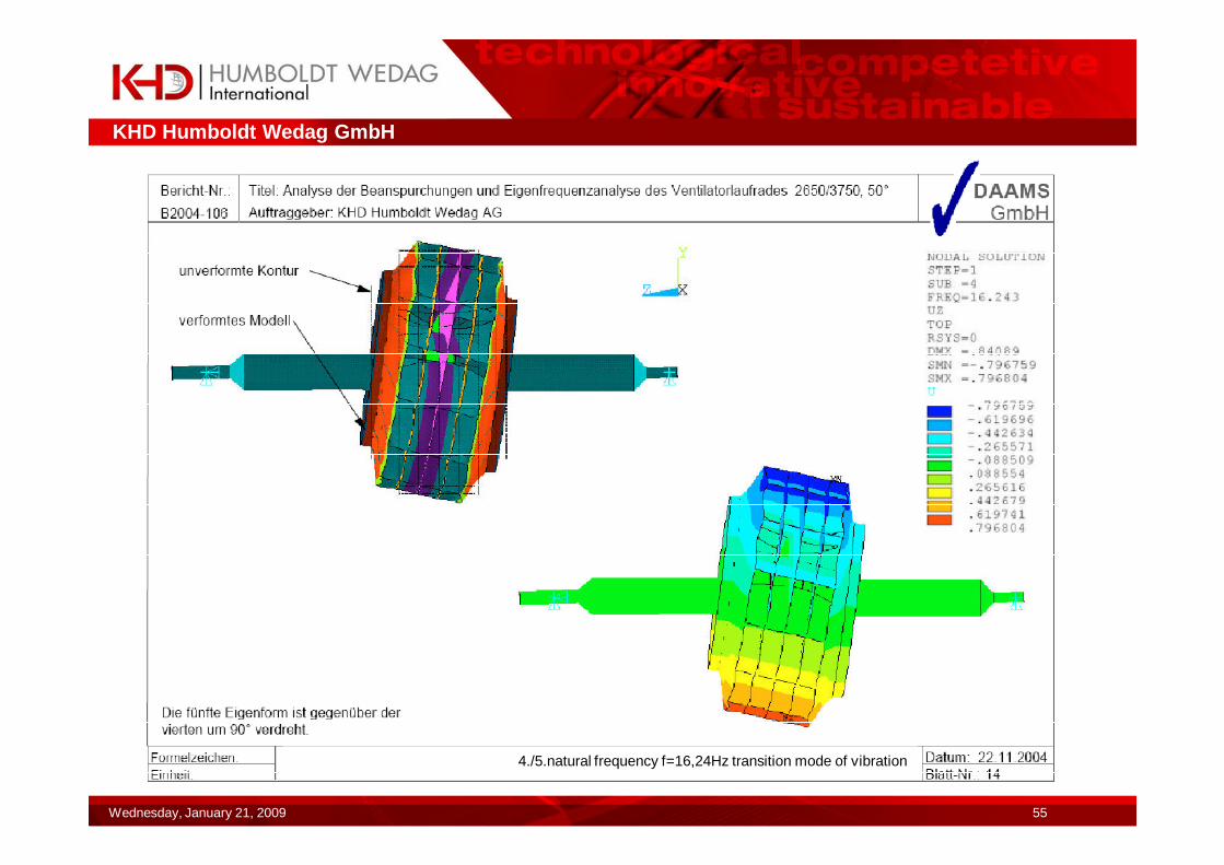
4./5.natural frequency f=16,24Hz transition mode of vibration

KHD Humboldt Wedag GmbH
Wednesday, January 21, 2009 56
Executed fans 2:
�Capacity increase of cementplant in turkey from of 1500t/day to 2500t/day:�By increasing of upper cyclonecover�By increasing of the waste gas duct/down comer�By new preheater fanPerformance data of new preheater-fan:� volume flow V: 7050 m³/min� pressure differenz ∆pst: 95 mbar� pressure differenz ∆pt: 97 mbar� temperature : 330°C� speed : 1030 1/min� power consumption Pw: 1530 kW� motor power: 1610 kW � content of dust: 25 g/m³� density at entree: 0,511 kg/m³
KHD Humboldt Wedag GmbH
Wednesday, January 21, 2009 57
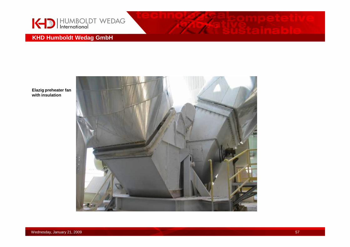
Elazig preheater fan with insulation

KHD Humboldt Wedag GmbH
Wednesday, January 21, 2009 58
Executed fans 3:
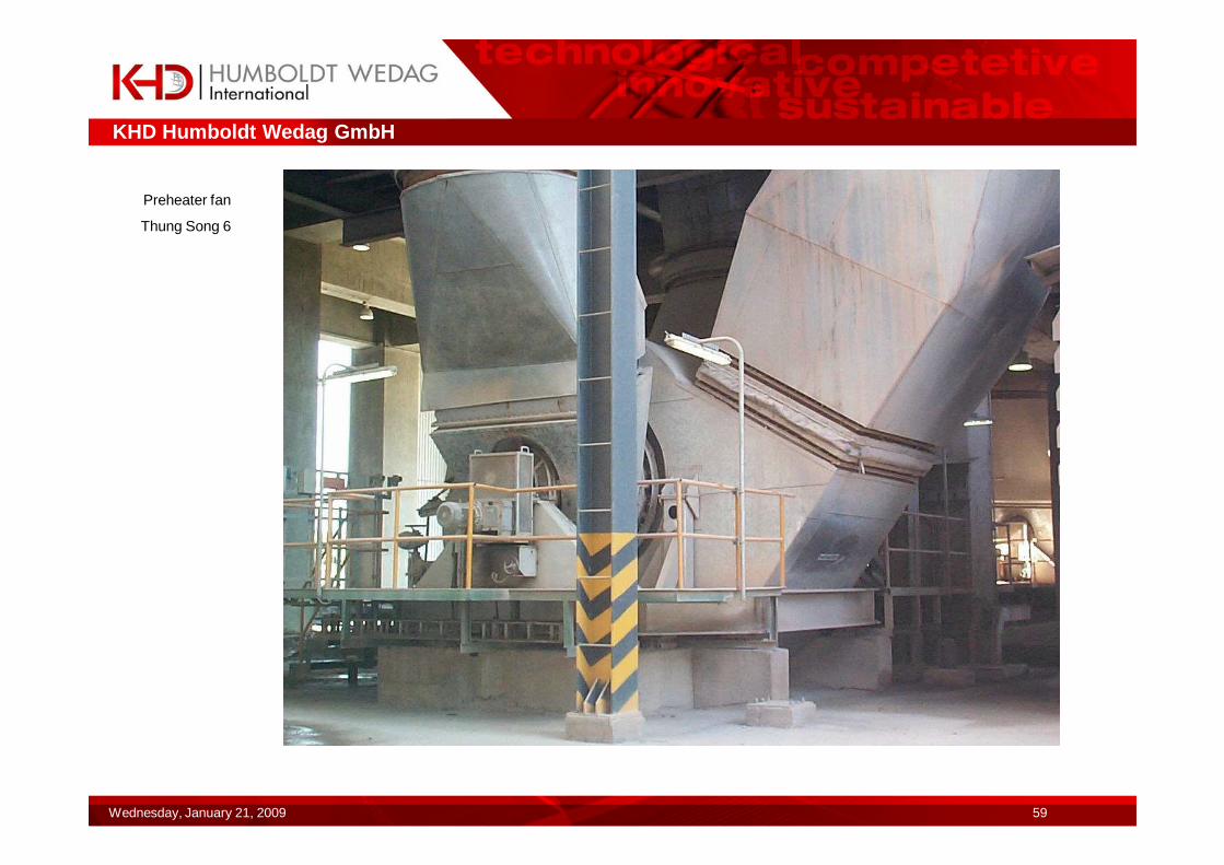
�Double inlet preheater fan Thung Song 6Performance datas of Preheater-fan Typ HKD170/300:� volume flow V: 9800 m³/min� pressure difference ∆pst: 75 mbar� pressure difference ∆pt: 79 mbar� temperature : 290°C� speed : 1000 1/min� power consumptionPw: 1674 kW� motor power: 1700 kW � content of dust: 25 g/m³� density at entree: 0,63 kg/m³
KHD Humboldt Wedag GmbH
Wednesday, January 21, 2009 59
Preheater fan
Thung Song 6
KHD Humboldt Wedag GmbH
Wednesday, January 21, 2009 60
Most powerful vertikal mill fan
�Double inlet mill fan Thung Song 5Performance data of mill-fan:� volume folw V: 18000 m³/min� pressure differenz ∆pst: 118 mbar� pressure differenz ∆pt: 124 mbar� temperature : 90°C� speed: 1000 1/min� power consumption Pw: 4886 kW� motor power: 5000 kW � content of dust: 30 g/m³� density at entree: 0,86 kg/m³
KHD Humboldt Wedag GmbH
Wednesday, January 21, 2009 61
Most powerful single inlet preheater fan
�Singel inlet preheater fan Kanthan/MalaysiaPerformance datas of preheater fan Typ HKS224/355:� volume flow V: 9500 m³/min� pressure differenz ∆pst: 93 mbar� temperature : 370°C� speed: 1000 1/min� power consumption Pw: 2030 kW� motor power: 2300 kW � content of dust: 25 g/m³� density at inlet: 0,55 kg/m³
KHD Humboldt Wedag GmbH
Wednesday, January 21, 2009 62
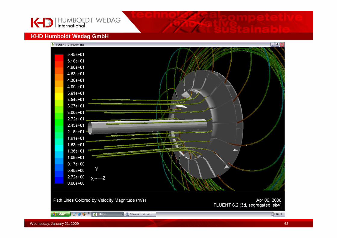
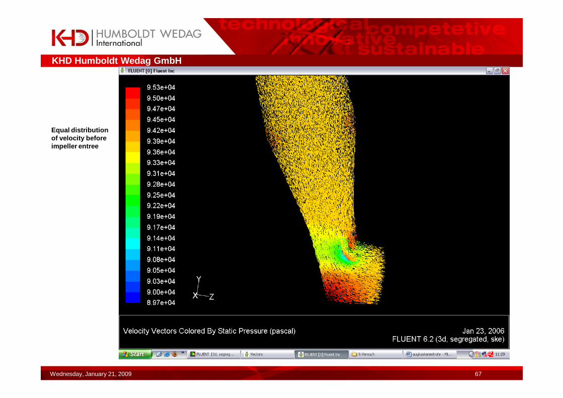
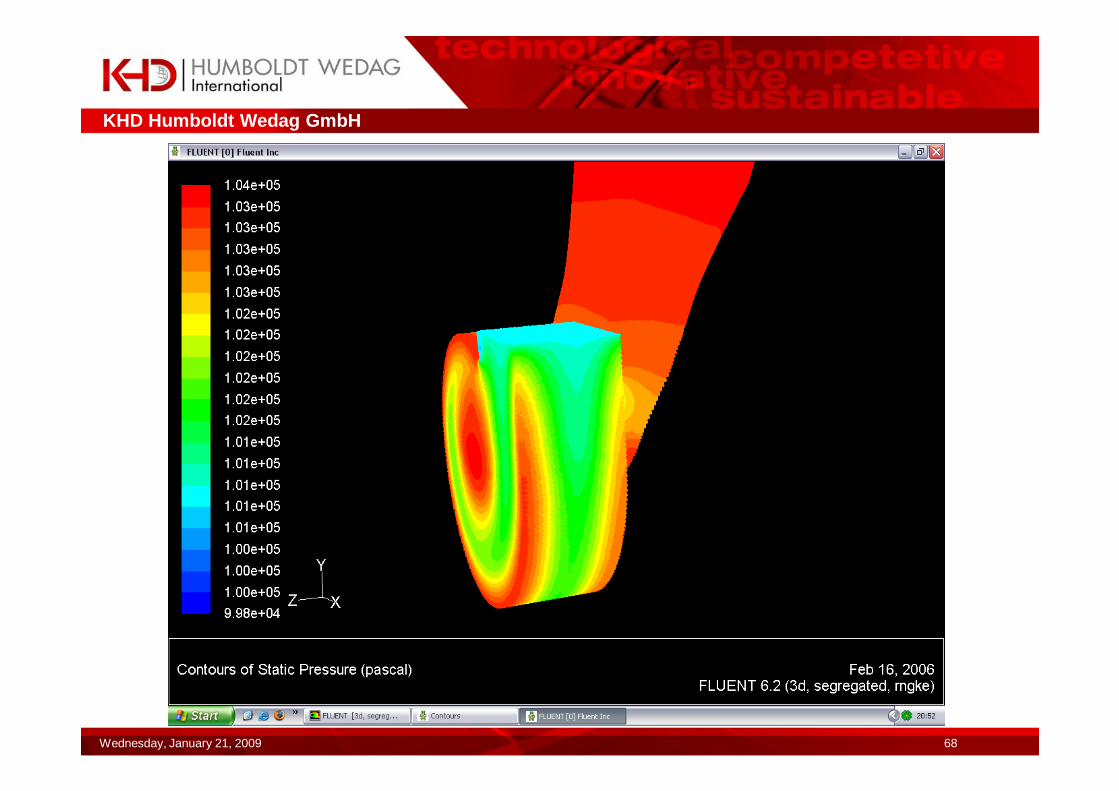
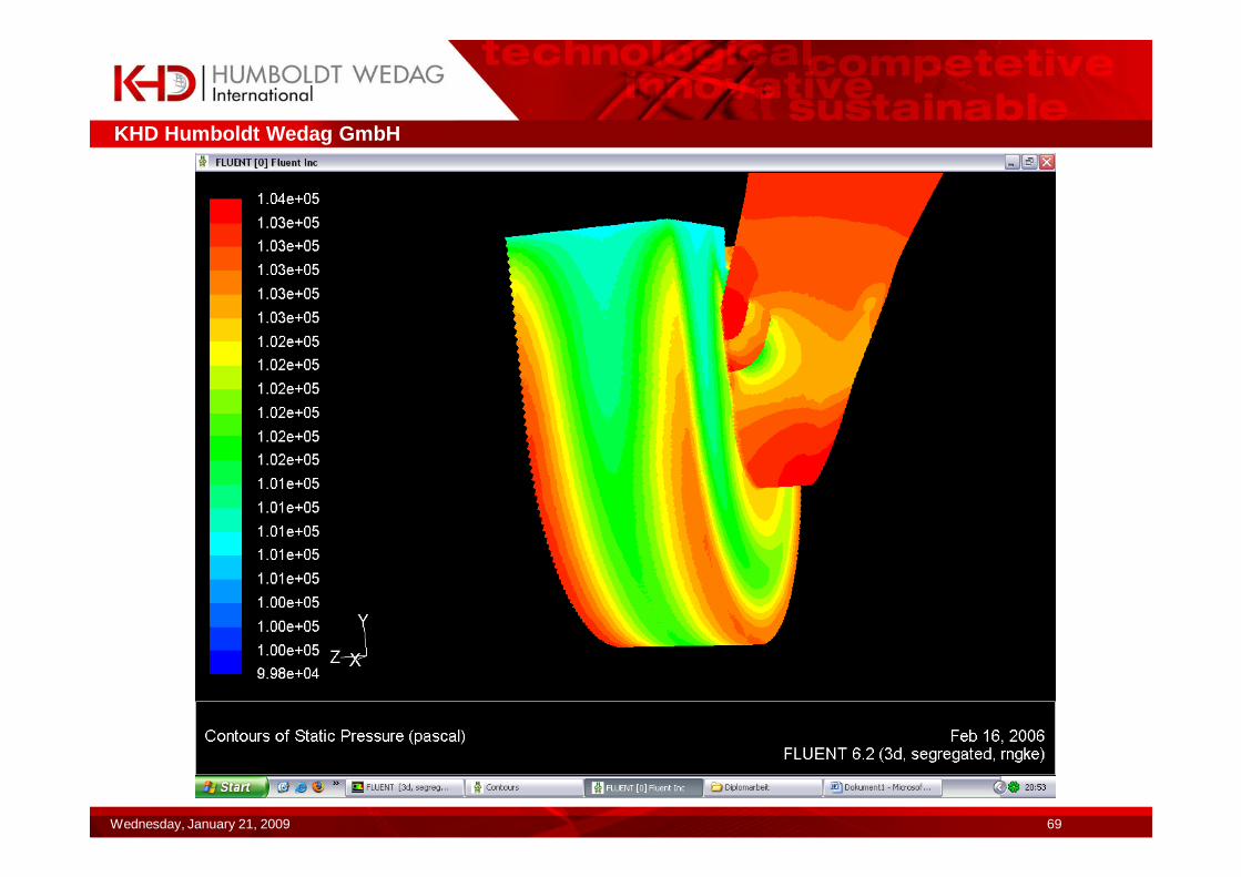
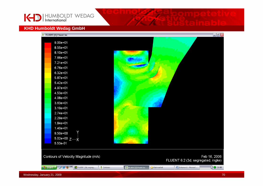
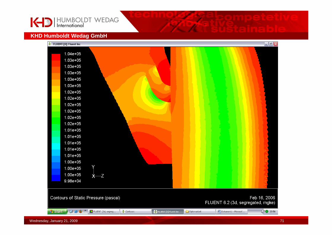
Investigation of gas flow in a high pressure fan
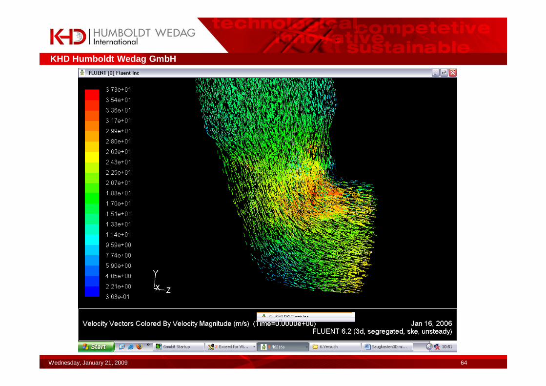
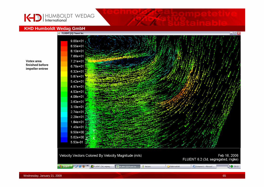
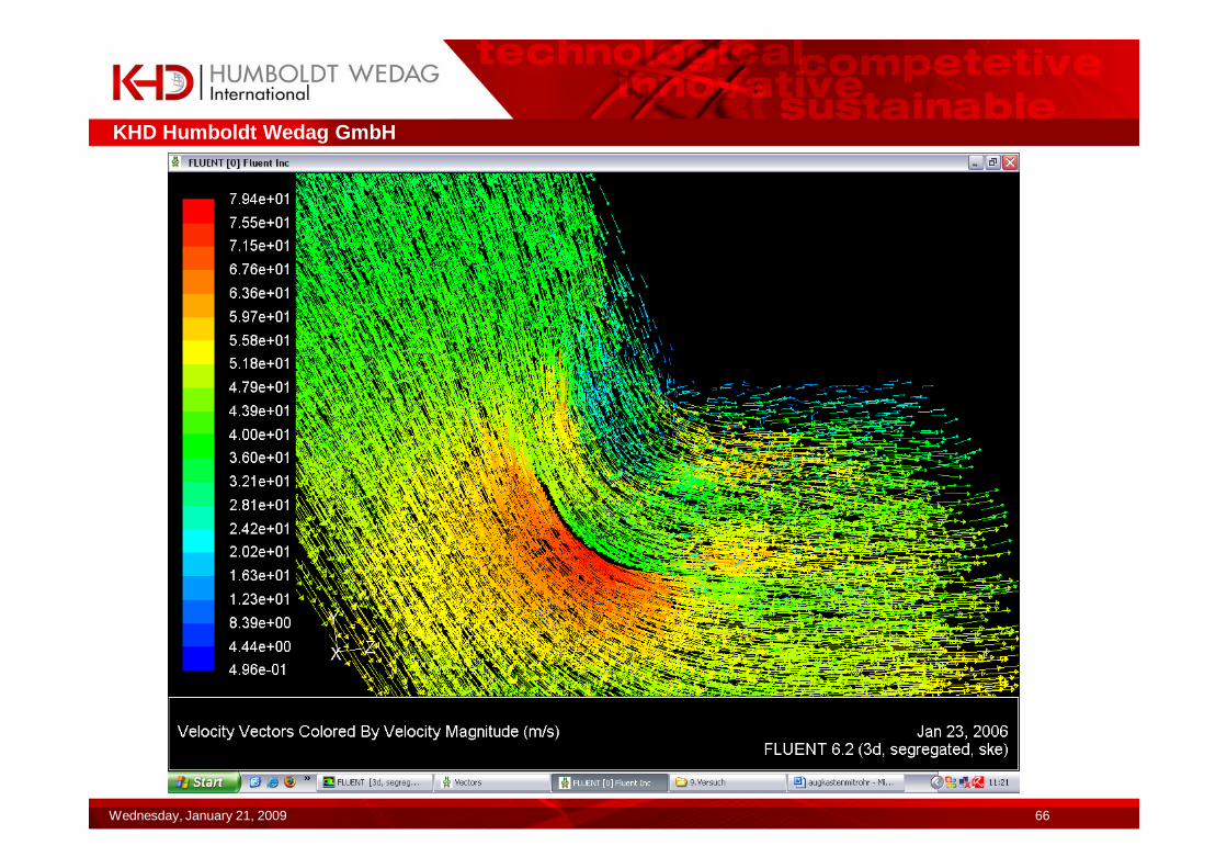
�At the following pictures the gas flow in the suction case with guide plates is shown.�First picture: deflection of gas flow in impeller. Notice the spinning free gas flow in front of impeller.�Further pictures: distribution of pressure and velocity in suction case/ fan housing.
KHD Humboldt Wedag GmbH
Wednesday, January 21, 2009 63
KHD Humboldt Wedag GmbH
Wednesday, January 21, 2009 64
KHD Humboldt Wedag GmbH
Wednesday, January 21, 2009 65
Votex area finished before impeller entree
KHD Humboldt Wedag GmbH
Wednesday, January 21, 2009 66
KHD Humboldt Wedag GmbH
Wednesday, January 21, 2009 67
Equal distribution of velocity before impeller entree
KHD Humboldt Wedag GmbH
Wednesday, January 21, 2009 68
KHD Humboldt Wedag GmbH
Wednesday, January 21, 2009 69
KHD Humboldt Wedag GmbH
Wednesday, January 21, 2009 70
KHD Humboldt Wedag GmbH
Wednesday, January 21, 2009 71