Embed Size (px)
Citation preview
2009 DEER ConferenceNovel Approach to Determine Oil Dilution
1
A Novel Approach in Determining Oil Dilution Level on a DPF Equipped Vehicle as a Result of
Regeneration
DEER August 6th
2009, Dearborn, MI USA
Harsha
Nanjundaswamy, Marek
Tatur, Dean TomazicFEV
Inc., Auburn Hills, MI USA
Andreas Wiartalla, Matthias Lamping, Thomas KoerferFEV
Motorentechnik
GmbH, Aachen, Germany
2009 DEER ConferenceNovel Approach to Determine Oil Dilution
2
Introduction
Fundamentals of novel approach
Results
Test setup
Test plans
Test data analysis
Conclusion
Table of Contents
2009 DEER ConferenceNovel Approach to Determine Oil Dilution
3
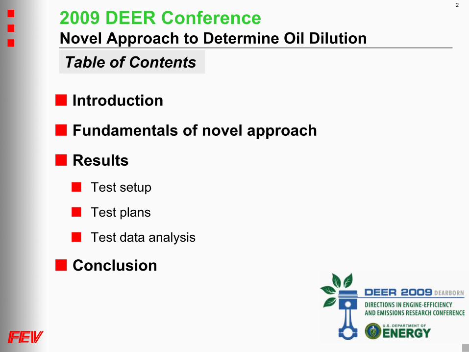
Oil dilution is detrimental to engine durability
More DPF and NAC equipped medium and light duty vehicles
In-cylinder late cycle diesel injection for regeneration and more
Critical for oil dilution
Challenge on positioning post injection strategy vs. oil dilution
Estimating in-use oil dilution not well understood other than expensive laboratory tests
Lambda based in-use oil dilution estimation
Conrod bearing wear
Visc
osity
Temperature
Visc
osity
Temperature
Visc
osity
Temperature
Visc
osity
Temperature
Oil dilution
Conrod bearing wear
Visc
osity
Temperature
Visc
osity
Temperature
Visc
osity
Temperature
Visc
osity
Temperature
Oil dilution
Introduction
Air
Fuel
HC
Fuel impingement or fuel vapor absorption.
This process is enhanced by late post
injection
Oil layer on the cylinder
walls
Blow by
Fuel diluted oil
Oil + Fuel
Air
Fuel
HC
Fuel impingement or fuel vapor absorption.
This process is enhanced by late post
injection
Oil layer on the cylinder
walls
Blow by
Fuel diluted oil
Oil + Fuel

2009 DEER ConferenceNovel Approach to Determine Oil Dilution
4
Lambda balance Fuel balance
Diesel-Loss [ DL
] is estimated as
POSITIVE diesel loss = Oil dilution
NEGATIVE diesel loss = Fuel evaporation
Mass of fuel loss to oil sump : mFL
= mF
* DL
S = Spindt = f(Exhaust Composition)
and / orS = Sensor
mFuel
V = mAir
mFuel * AFR
mAir mExhaust
Diesel FuelEngine Oil
Balance Border Line
Blow-By
EGR
DieselLoss (DL)
S = Spindt = f(Exhaust Composition)
and / orS = Sensor
mFuel
V = mAir
mFuel * AFR
mAir mExhaust
Diesel FuelEngine Oil
Balance Border Line
Blow-By
EGR
DieselLoss (DL)
DL =S - V
S* 100 %DL =
S - V
S* 100 %
Fundamentals : Novel approach methodology
mFL
mE
mF
mFL
mE
mF

2009 DEER ConferenceNovel Approach to Determine Oil Dilution
5
Post injection
DPF regeneration
NAC regeneration
NAC desulfurization
In-cylinder soot reduction Fuel in oil
Fuel vapor absorption
Fuel injection wall wetting
Late cycle injection
Cylinder charge leak and condensation
Fuel evaporation
Diffusion off the oil layer in cylinder
Blow by
Engine speed
BMEP
Post injection strategiesFundamentals : Oil dilution phenomenon
1
2
3
4
5
6
7
8
1 Fuel absorption by oil film
2 Blow-by transports fuel
3 Oil feed from sump to liner film
4 Oil drain back into the crankcasecarrying absorbed fuel
5 Breather gases leave the crankcase carrying vaporized fuel
6 Part of the liner film is burnt during combustion stroke
7 Desorbtion of fuel components
8 Fuel desorbtion into the breather gases
1
2
3
4
5
6
7
8
11
22
333
444
555
66
77
88
1 Fuel absorption by oil film
2 Blow-by transports fuel
3 Oil feed from sump to liner film
4 Oil drain back into the crankcasecarrying absorbed fuel
5 Breather gases leave the crankcase carrying vaporized fuel
6 Part of the liner film is burnt during combustion stroke
7 Desorbtion of fuel components
8 Fuel desorbtion into the breather gases

2009 DEER ConferenceNovel Approach to Determine Oil Dilution
6
Data analysis
Vehicle setup for oil dilution estimation
ECU
Engine Aftertreatment system
Lambda OUT
Lambda IN
Results : Test setupTEST CELL
Coriolis
type fuel mass flow measurement
Dynamic high accurate air mass flow measurement
Blowby
separator with bypass
Complete exhaust instrumentation
Lambda sensor
Emissions measurement and Lambda exhaust
Smoke and PM measurement
Temperature and pressure
VEHICLE
Air and fuel measurement through ECU
Vehicle instrumentation to gather temperature and pressure signals
Exhaust Lambda sensors
Test cell setup for oil dilution estimation
EngineBlow by separator with bypass
INTAKE
Air mass flow measurement
Fuel mass flow
measurement
EXHAUST
DOC and NAC
DPF Tailpipe
LambdaGaseous EmissionsSmokePMTemperature Pressure
Combustion analyzer
EngineBlow by separator with bypass
INTAKE
Air mass flow measurement
Fuel mass flow
measurement
EXHAUST
DOC and NAC
DPF Tailpipe
LambdaGaseous EmissionsSmokePMTemperature Pressure
Combustion analyzer

2009 DEER ConferenceNovel Approach to Determine Oil Dilution
7
Results : Test plan
Test cell Oil dilution estimation
Oil change interval simulation through vehicle test correlation
ECU executed in-cylinder post injection based regenerations
Extended study
Extended oil change interval
Blow by effect
Oil ageing study over time
Vehicle tests
Statistics of diesel loss for regeneration of DPF & NAC as well as normal engine operation in both city and highway driving
Correlation of the vehicle tests to test cell for controlled engine testing to study the diesel loss method
Regular operationCool down
DPFRegeneration
Cool downRegular operation
Engine speed
Torque
Soot load in DPF
Pressure drop
DPF temperature
Regular operationCool down
DPFRegeneration
Cool downRegular operation
Engine speed
Torque
Soot load in DPF
Pressure drop
DPF temperature
Time
Regeneration
Fuel in 5537 gmFuel out 5017 gmDiesel loss 9.39 %
Fuel IN Fuel OUT
NO RegenerationFuel in 2003.45 gmFuel out 2087.12 gmDiesel loss -4.17 %
Die
sel l
oss
[%]
-20
-10
0
10
20
30
40
50
Calculated diesel loss

2009 DEER ConferenceNovel Approach to Determine Oil Dilution
8
Results : Test data analysis
Regeneration mode Non Regeneration mode
Time
Lam
bda
[-]
1.01.52.02.53.03.54.0
Lambda - IN Lambda - OUT
Acc
umul
ated
fuel
[g]
-500
50100150200250
Lambda IN < Lambda OUT
Lambda IN > Lambda OUT
Fuel
loss
[g/s
]
-0.5
-0.3
-0.1
0.1
0.3
0.5
Zero line
Negative
Positive ∆
= 0.08
∆
= 0.03
Regeneration mode has dominant diesel loss
Regular engine operation mode is dominated by fuel evaporation

2009 DEER ConferenceNovel Approach to Determine Oil Dilution
9
Results : Test data analysisFu
elev
apor
atio
n [%
]
-10-8-6-4-202
Time [hr]0 2 4 6 8 10 12 14 16 18
Fuel
loss
[%]
05
101520253035
Time [hr]0 2 4 6 8 10 12
Fuel loss during regeneration andsimilar aggressive oil dilution events
Fuel evaporation during normalengine operation
Net
Oil
dilu
tion
[%]
0
5
10
15
20
25
Time [hr]0 5 10 15 20 25 30
Net oil dilution
Aggressive oildilution rates
Dominant fuel evaporationminimizing the dilution rateReduced oil dilution rates
due to dominant fuelevaporation rates
Weak fuelevaporation rates
Aggressive fuelevaporation rates

2009 DEER ConferenceNovel Approach to Determine Oil Dilution
10
Test data analysis boundaries
Tight control on evaluating oil and fuel consumptions
Correlation between vehicle and test cell engine was established also on miles vs. fuel consumption
Steady state engine operating points chosen based on vehicle test results to meet fuel evaporation rates
Focus on worst case scenario
Actual analysis of the oil done through gas chromatography
Good correlation between estimation vs. actual60
70
80
90
100
110
120
1
Perc
ent v
alue
[%]
Gas chromatographyFEV oil dilution estimation
∆ of 2%
Results : Test data analysis
2009 DEER ConferenceNovel Approach to Determine Oil Dilution
11
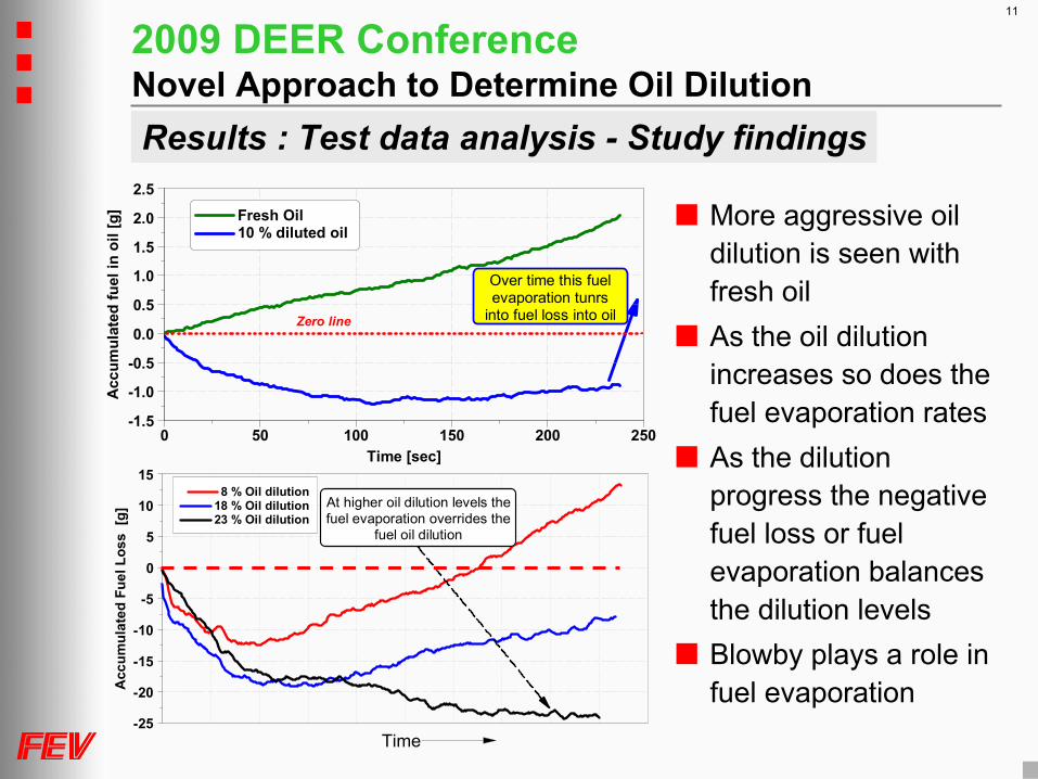
More aggressive oil dilution is seen with fresh oil
As the oil dilution increases so does the fuel evaporation rates
As the dilution progress the negative fuel loss or fuel evaporation balances the dilution levels
Blowby
plays a role in fuel evaporation
Zero line
Acc
umul
ated
fuel
in o
il [g
]
-1.5
-1.0
-0.5
0.0
0.5
1.0
1.5
2.0
2.5
Time [sec]0 50 100 150 200 250
Fresh Oil 10 % diluted oil
Over time this fuelevaporation tunrs
into fuel loss into oil
Time
Acc
umul
ated
Fue
l Los
s [g
]
-25
-20
-15
-10
-5
0
5
10
15
At higher oil dilution levels thefuel evaporation overrides the
fuel oil dilution
8 % Oil dilution 18 % Oil dilution 23 % Oil dilution
Results : Test data analysis -
Study findings

2009 DEER ConferenceNovel Approach to Determine Oil Dilution
12
Acc
umul
ated
Fue
l Los
s [g
]
-30
-25
-20
-15
-10
-5
0
Time [sec]0 200 400 600 800 1000 1200
Base - SETUP 1 Filtered Blow-By - SETUP 2
Blow byfiltering
1 2
2
1
With blowby and no fuel fume separation [1] it is clear that there is more fuel evaporation is observed
With blowby with fuel fumes separation the net fuel evaporation is greatly reduced
This proves the fact that fuel evaporation from oil is present and greatly influenced by blowby
Results : Test data analysis -
Study findings
2009 DEER ConferenceNovel Approach to Determine Oil Dilution
13
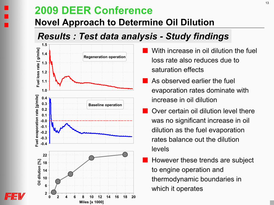
With increase in oil dilution the fuel loss rate also reduces due to saturation effects
As observed earlier the fuel evaporation rates dominate with increase in oil dilution
Over certain oil dilution level there was no significant increase in oil dilution as the fuel evaporation rates balance out the dilution levels
However these trends are subject to engine operation and thermodynamic boundaries in which it operates
Results : Test data analysis -
Study findingsFu
el lo
ss ra
te [
g/m
ile]
1.0
1.1
1.2
1.3
1.4
1.5
Fuel
eva
pora
tion
rate
[g/m
ile]
-0.4-0.3-0.2-0.1-0.00.10.20.30.4
Baseline operation
Regeneration operation
Oil
dilu
tion
[%]
2
6
10
14
18
22
Miles [x 1000]0 2 4 6 8 10 12 14 16 18 20

2009 DEER ConferenceNovel Approach to Determine Oil Dilution
14
Findings
Oil dilution rate is a function of dilution effects such as late
post injection and evaporation rates during regular operation
Fuel evaporation of the oil layer is subject to blowby rates and
oil temperatures
The oil dilution rate varies with respect to dilution level, so does the evaporation rates
Oil dilution estimation is subject to accuracy of the measurement
0.0
5.0
10.0
15.0
20.0
25.0
30.0
1 hr operation 2 hr operation 2000 5000 10000 17500
Miles
Oil
dilu
tion
[%]
Gas chromatographyFEV oil dilution estimation
DPF regeneration only
Results : Test data analysis -
Statistics

2009 DEER ConferenceNovel Approach to Determine Oil Dilution
15
Conclusion
The novel approach determines the oil dilution within 2 –
20% accuracy
This approach can be easily adopted for developing optimum engine calibration meeting performance, emissions and oil dilution
This novel approach of oil dilution estimation would help avoid issues that may arise with fixed oil change intervals
Oil dilution degradation as a result of varying drive cycle
Avoid severe degradation of oil quality before specified oil change interval
At many instances increase the oil change interval beyond specific miles limit
Implementation of this methodology does not demand new sensors but a new strategy
Accuracy of the measurement signals and noise elimination is crucial for the quality of estimation