Embed Size (px)
Citation preview
SECTION 501-35: Body Repairs 2008 Crown Victoria/Grand Marquis Workshop ManualREMOVAL AND INSTALLATION Procedure revision date: 01/25/2010
Ballistic Door Panel
Special Tool(s)
Heavy Duty Riveter501-D011 (D80L-23200-A) or equivalent
Ballistic Door Panel Insert
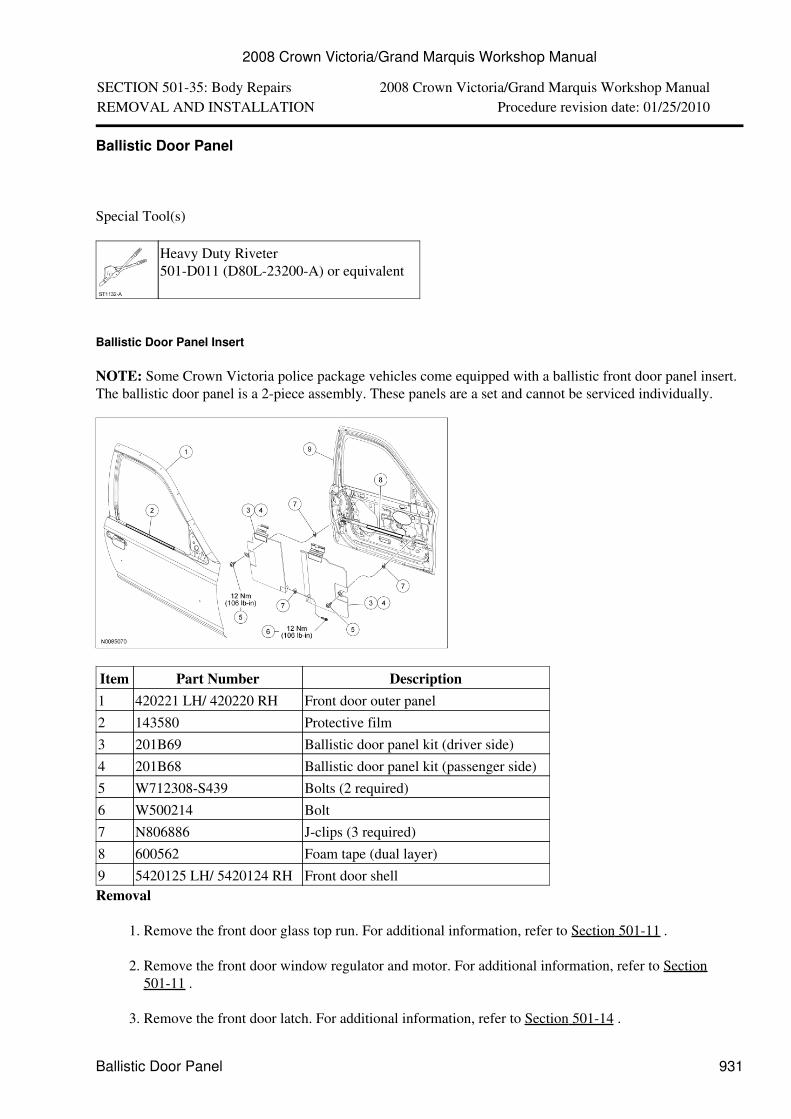
NOTE: Some Crown Victoria police package vehicles come equipped with a ballistic front door panel insert.The ballistic door panel is a 2-piece assembly. These panels are a set and cannot be serviced individually.
Item Part Number Description1 420221 LH/ 420220 RH Front door outer panel2 143580 Protective film3 201B69 Ballistic door panel kit (driver side)4 201B68 Ballistic door panel kit (passenger side)5 W712308-S439 Bolts (2 required)6 W500214 Bolt7 N806886 J-clips (3 required)8 600562 Foam tape (dual layer)9 5420125 LH/ 5420124 RH Front door shellRemoval
Remove the front door glass top run. For additional information, refer to Section 501-11 .1.
Remove the front door window regulator and motor. For additional information, refer to Section501-11 .
2.
Remove the front door latch. For additional information, refer to Section 501-14 .3.
2008 Crown Victoria/Grand Marquis Workshop Manual
Ballistic Door Panel 931
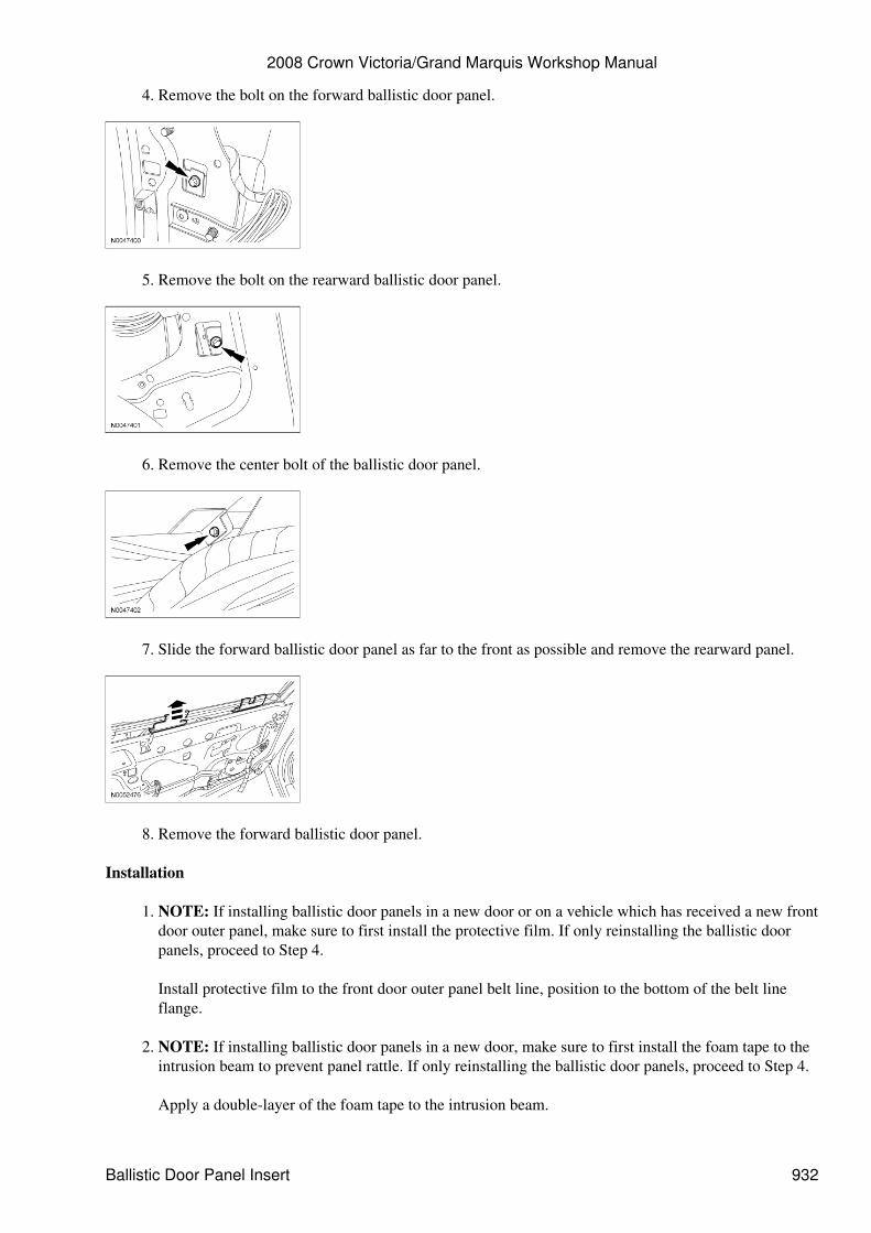
Remove the bolt on the forward ballistic door panel.4.
Remove the bolt on the rearward ballistic door panel.5.
Remove the center bolt of the ballistic door panel.6.
Slide the forward ballistic door panel as far to the front as possible and remove the rearward panel.7.
Remove the forward ballistic door panel.8.
Installation
NOTE: If installing ballistic door panels in a new door or on a vehicle which has received a new frontdoor outer panel, make sure to first install the protective film. If only reinstalling the ballistic doorpanels, proceed to Step 4.
Install protective film to the front door outer panel belt line, position to the bottom of the belt lineflange.
1.
NOTE: If installing ballistic door panels in a new door, make sure to first install the foam tape to theintrusion beam to prevent panel rattle. If only reinstalling the ballistic door panels, proceed to Step 4.
Apply a double-layer of the foam tape to the intrusion beam.
2.
2008 Crown Victoria/Grand Marquis Workshop Manual
Ballistic Door Panel Insert 932
Install the J-clips.3.
Insert the forward ballistic door panel through the window opening and hook the top bracket over theouter belt line sheet metal.
Position as far forward as possible.•
4.
Insert the rearward ballistic door panel through the window opening and hook the top bracket over theouter belt line sheet metal.
Slide the forward panel back until mated with the rearward panel.•
5.
Align the panels so the ceramic plate bottoms out against the adjacent panel.6.
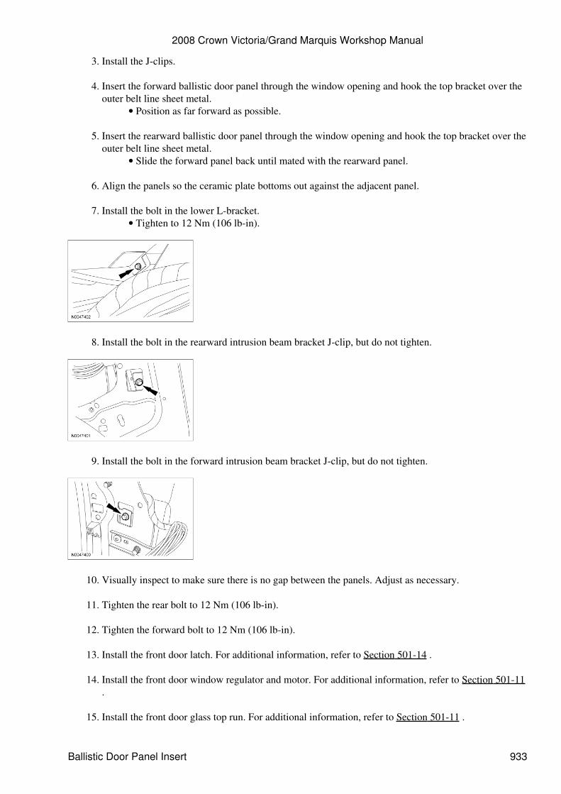
Install the bolt in the lower L-bracket.Tighten to 12 Nm (106 lb-in).•
7.
Install the bolt in the rearward intrusion beam bracket J-clip, but do not tighten.8.
Install the bolt in the forward intrusion beam bracket J-clip, but do not tighten.9.
Visually inspect to make sure there is no gap between the panels. Adjust as necessary.10.
Tighten the rear bolt to 12 Nm (106 lb-in).11.
Tighten the forward bolt to 12 Nm (106 lb-in).12.
Install the front door latch. For additional information, refer to Section 501-14 .13.
Install the front door window regulator and motor. For additional information, refer to Section 501-11.
14.
Install the front door glass top run. For additional information, refer to Section 501-11 .15.
2008 Crown Victoria/Grand Marquis Workshop Manual
Ballistic Door Panel Insert 933

Apply the BALLISTIC PANEL label to the door trim panel just forward of the door latch handle.16.
2008 Crown Victoria/Grand Marquis Workshop Manual
Ballistic Door Panel Insert 934
SECTION 501-35: Body Repairs 2008 Crown Victoria/Grand Marquis Workshop ManualREMOVAL AND INSTALLATION Procedure revision date: 10/03/2008
Inner Body Reinforcing Panels
General Equipment
3 Phase Inverter Spot Welder 254-00002Compuspot 700F Welder 190-50080I4 Inverter Spot Welder 254-00014Inverter Welder with MIG Welder 254-00015
Material
Item SpecificationMetal Bonding AdhesiveTA-1
--
Motorcraft® Metal Surface PrepZC-31-A
--
Premium UndercoatingValuGard™ VG101, VG101A(aerosol)
--
Rust InhibitorValuGard™ VG104, VG104A(aerosol)
--
Seam SealerTA-2
--
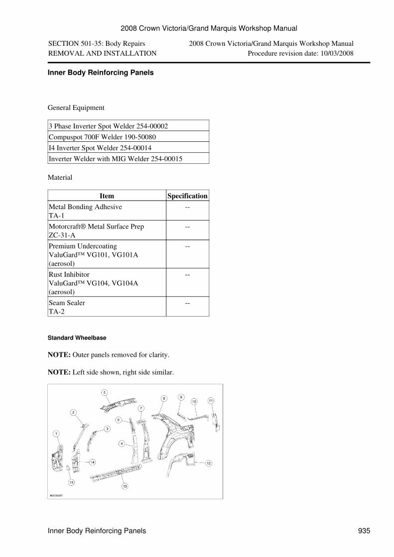
Standard Wheelbase
NOTE: Outer panels removed for clarity.
NOTE: Left side shown, right side similar.
2008 Crown Victoria/Grand Marquis Workshop Manual
Inner Body Reinforcing Panels 935
Item Part Number Description1 02039 LH/
02038 RHCowl side panel -- high-strength steel
2 02509 LH/02508 RH
Front body pillar -- high-strength steel
3 02505 LH/02504 RH
Front body upper pillar -- mild steel
4 24301 LH/24300 RH
Center body pillar -- high-strength steel
5 51181 LH/51180 RH
Roof side inner rail -- high-strength steel
6 -- Front seat shoulder strap reinforcement (LH/RH) --high-strength steel (part of 24301/24300)
7 24301 LH/24300 RH
Center body pillar serviced as assembly with No. 4-- high-strength steel
8 27791 LH/27790 RH
Quarter panel inner -- high-strength steel
9 602A11 Rear seat shoulder strap reinforcement --high-strength steel
10 278B11 LH/278B10 RH
Quarter panel extension -- mild steel
11 45115 LH/45114 RH
Luggage compartment drain trough -- mild steel
12 27887 LH/27886 RH
Quarter panel inner wheelhouse -- mild steel
13 20403 LH/20402 RH
Door frame opening reinforcement -- high-strengthsteel
14 22843 LH/22842 RH
Front door hinge reinforcement -- high-strengthsteel
15 204A07 LH/204A06 RH
Door frame reinforcement -- high-strength steel
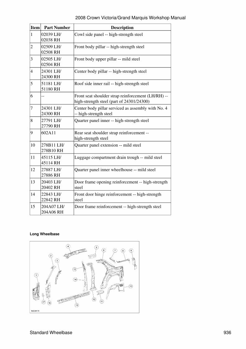
Long Wheelbase
2008 Crown Victoria/Grand Marquis Workshop Manual
Standard Wheelbase 936
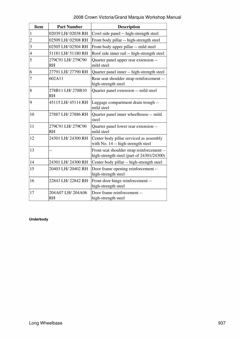
Item Part Number Description1 02039 LH/ 02038 RH Cowl side panel -- high-strength steel2 02509 LH/ 02508 RH Front body pillar -- high-strength steel3 02505 LH/ 02504 RH Front body upper pillar -- mild steel4 51181 LH/ 51180 RH Roof side inner rail -- high-strength steel5 279C91 LH/ 279C90
RHQuarter panel upper rear extension --mild steel
6 27791 LH/ 27790 RH Quarter panel inner -- high-strength steel7 602A11 Rear seat shoulder strap reinforcement --
high-strength steel8 278B11 LH/ 278B10
RHQuarter panel extension -- mild steel
9 45115 LH/ 45114 RH Luggage compartment drain trough --mild steel
10 27887 LH/ 27886 RH Quarter panel inner wheelhouse -- mildsteel
11 279C91 LH/ 279C90RH
Quarter panel lower rear extension --mild steel
12 24301 LH/ 24300 RH Center body pillar serviced as assemblywith No. 14 -- high-strength steel
13 -- Front seat shoulder strap reinforcement --high-strength steel (part of 24301/24300)
14 24301 LH/ 24300 RH Center body pillar -- high-strength steel15 20403 LH/ 20402 RH Door frame opening reinforcement --
high-strength steel16 22843 LH/ 22842 RH Front door hinge reinforcement --
high-strength steel17 204A07 LH/ 204A06
RHDoor frame reinforcement --high-strength steel
Underbody
2008 Crown Victoria/Grand Marquis Workshop Manual
Long Wheelbase 937
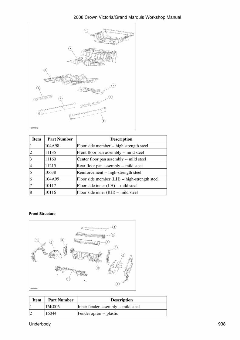
Item Part Number Description1 104A98 Floor side member -- high strength steel2 11135 Front floor pan assembly -- mild steel3 11160 Center floor pan assembly -- mild steel4 11215 Rear floor pan assembly -- mild steel5 10638 Reinforcement -- high-strength steel6 104A99 Floor side member (LH) -- high-strength steel7 10117 Floor side inner (LH) -- mild steel8 10116 Floor side inner (RH) -- mild steel
Front Structure
Item Part Number Description1 16K006 Inner fender assembly -- mild steel2 16044 Fender apron -- plastic
2008 Crown Victoria/Grand Marquis Workshop Manual
Underbody 938
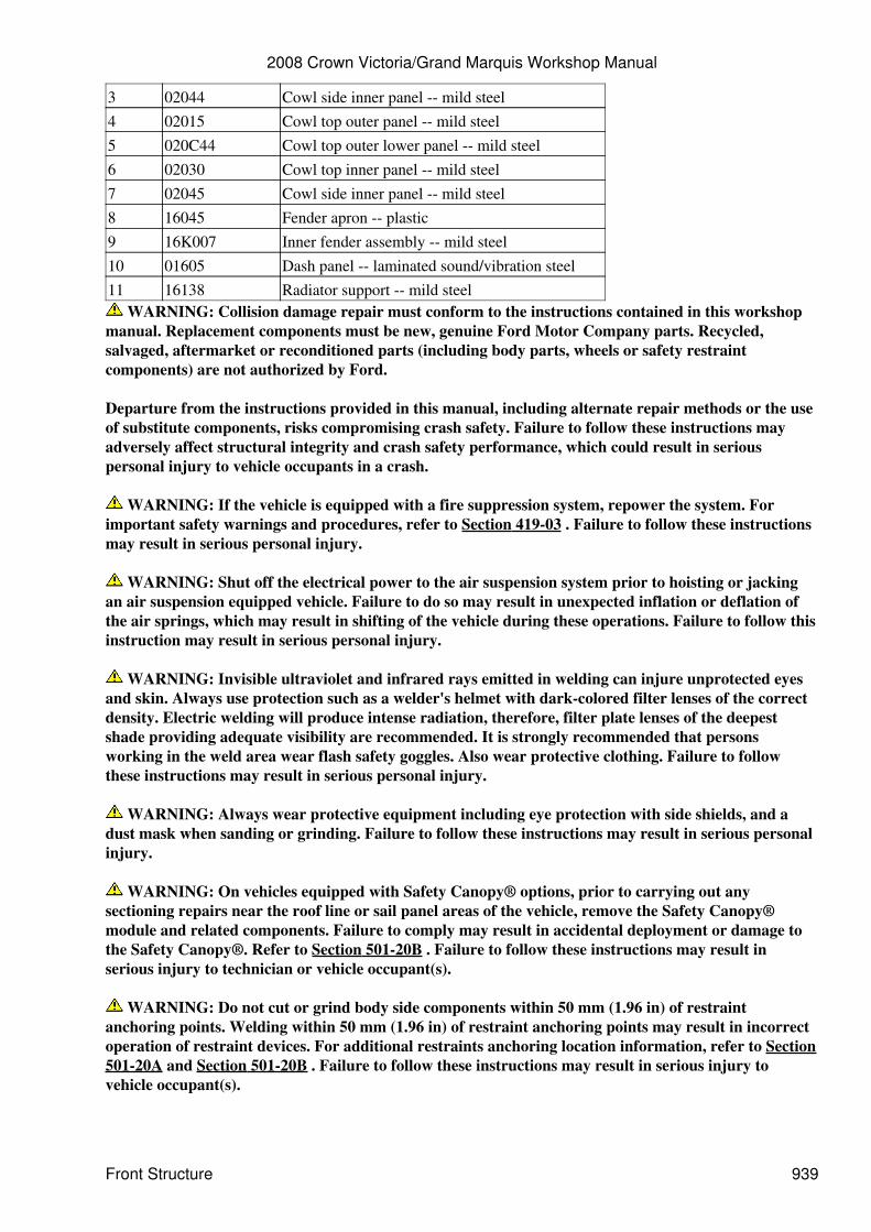
3 02044 Cowl side inner panel -- mild steel4 02015 Cowl top outer panel -- mild steel5 020C44 Cowl top outer lower panel -- mild steel6 02030 Cowl top inner panel -- mild steel7 02045 Cowl side inner panel -- mild steel8 16045 Fender apron -- plastic9 16K007 Inner fender assembly -- mild steel10 01605 Dash panel -- laminated sound/vibration steel11 16138 Radiator support -- mild steel
WARNING: Collision damage repair must conform to the instructions contained in this workshopmanual. Replacement components must be new, genuine Ford Motor Company parts. Recycled,salvaged, aftermarket or reconditioned parts (including body parts, wheels or safety restraintcomponents) are not authorized by Ford.
Departure from the instructions provided in this manual, including alternate repair methods or the useof substitute components, risks compromising crash safety. Failure to follow these instructions mayadversely affect structural integrity and crash safety performance, which could result in seriouspersonal injury to vehicle occupants in a crash.
WARNING: If the vehicle is equipped with a fire suppression system, repower the system. Forimportant safety warnings and procedures, refer to Section 419-03 . Failure to follow these instructionsmay result in serious personal injury.
WARNING: Shut off the electrical power to the air suspension system prior to hoisting or jackingan air suspension equipped vehicle. Failure to do so may result in unexpected inflation or deflation ofthe air springs, which may result in shifting of the vehicle during these operations. Failure to follow thisinstruction may result in serious personal injury.
WARNING: Invisible ultraviolet and infrared rays emitted in welding can injure unprotected eyesand skin. Always use protection such as a welder's helmet with dark-colored filter lenses of the correctdensity. Electric welding will produce intense radiation, therefore, filter plate lenses of the deepestshade providing adequate visibility are recommended. It is strongly recommended that personsworking in the weld area wear flash safety goggles. Also wear protective clothing. Failure to followthese instructions may result in serious personal injury.
WARNING: Always wear protective equipment including eye protection with side shields, and adust mask when sanding or grinding. Failure to follow these instructions may result in serious personalinjury.
WARNING: On vehicles equipped with Safety Canopy® options, prior to carrying out anysectioning repairs near the roof line or sail panel areas of the vehicle, remove the Safety Canopy®module and related components. Failure to comply may result in accidental deployment or damage tothe Safety Canopy®. Refer to Section 501-20B . Failure to follow these instructions may result inserious injury to technician or vehicle occupant(s).
WARNING: Do not cut or grind body side components within 50 mm (1.96 in) of restraintanchoring points. Welding within 50 mm (1.96 in) of restraint anchoring points may result in incorrectoperation of restraint devices. For additional restraints anchoring location information, refer to Section501-20A and Section 501-20B . Failure to follow these instructions may result in serious injury tovehicle occupant(s).
2008 Crown Victoria/Grand Marquis Workshop Manual
Front Structure 939
NOTICE: Electronic modules and related wiring can be damaged when exposed to heat from weldingprocedures. Carefully disconnect and remove, or position away from heat-affected areas.
NOTE: When it is necessary to carry out weld-bonding procedures, refer to Weld-Bonding in this section.
Remove the outer body sheet metal from the affected area prior to carrying out any reinforcing panelreplacement. For additional information, refer to Sectioning Guidelines in this section.
1.
NOTE: Factory spot welds may be substituted with either resistance spot welds or Metal Inert Gas (MIG)plug welds. Spot/plug welds should equal factory welds in both location and quantity. Do not place a new spotweld directly over an original weld location. Plug weld hole should equal 8 mm (0.31 in) diameter.
NOTE: Observe prescribed welding procedures when carrying out any body side section repair. Foradditional information, refer to Welding Precautions -- Steel in this section.
NOTICE: Electronic modules and related wiring can be damaged when exposed to heat fromwelding procedures. Carefully disconnect and remove, or position away from heat affectedareas. For additional information, refer to Welding Precautions -- Steel in this section.
NOTE: When it is necessary to carry out weld-bonding procedures, refer to Weld-Bonding in thissection.
Remove the outer body sheet metal from the affected area prior to carrying out any reinforcing panelreplacement. For additional information, refer to Sectioning Guidelines in this section.
2.
When welding overlapping surfaces or substrates, apply corrosion protection material between thesurfaces prior to welding. When the surfaces have been welded, apply corrosion protection material tothe exterior surfaces or substrates. For additional information, refer to Restoring Corrosion ProtectionFollowing Repair in this section.
Make sure horizontal joints and flanges are correctly sealed with seam sealer to preventmoisture intrusion. Water and moisture migrate to horizontal joints and corrosion tends tooccur more rapidly in these areas. Metal surfaces must be clean and dry before applying seamsealer.
•
3.
If equipped with a fire suppression system, repower the system. For important safety warnings andprocedures, refer to Section 419-03 .
4.
If equipped with an air suspension system, reactivate the power supply. This can be accomplished byreconnecting the battery or turning on the air suspension service switch located in the luggagecompartment on the LH side.
5.
Proceed with the refinish process following Ford-approved paint recommendations.6.
2008 Crown Victoria/Grand Marquis Workshop Manual
Front Structure 940

2008 Crown Victoria/Grand Marquis Workshop Manual
Front Structure 941
SECTION 502-02: Full Frame and BodyMounting
2008 Crown Victoria/Grand Marquis WorkshopManual
SPECIFICATIONS Procedure revision date: 06/14/2007
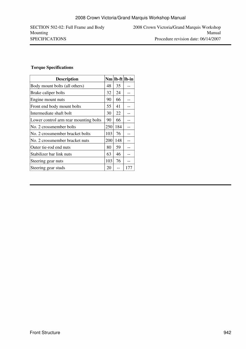
Torque Specifications
Description Nm lb-ft lb-inBody mount bolts (all others) 48 35 --Brake caliper bolts 32 24 --Engine mount nuts 90 66 --Front end body mount bolts 55 41 --Intermediate shaft bolt 30 22 --Lower control arm rear mounting bolts 90 66 --No. 2 crossmember bolts 250 184 --No. 2 crossmember bracket bolts 103 76 --No. 2 crossmember bracket nuts 200 148 --Outer tie-rod end nuts 80 59 --Stabilizer bar link nuts 63 46 --Steering gear nuts 103 76 --Steering gear studs 20 -- 177
2008 Crown Victoria/Grand Marquis Workshop Manual
Front Structure 942
SECTION 502-02: Full Frame and Body Mounting 2008 Crown Victoria/Grand MarquisWorkshop Manual
DESCRIPTION AND OPERATION Procedure revision date: 12/02/2010
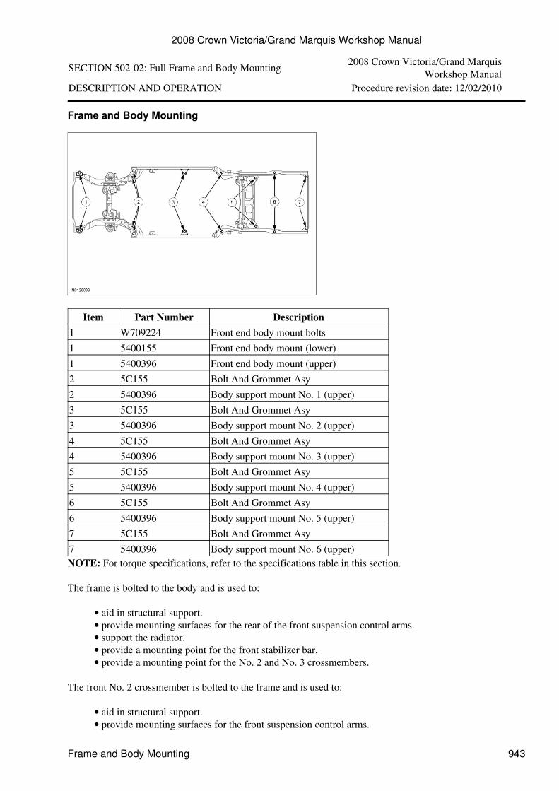
Frame and Body Mounting
Item Part Number Description1 W709224 Front end body mount bolts1 5400155 Front end body mount (lower)1 5400396 Front end body mount (upper)2 5C155 Bolt And Grommet Asy2 5400396 Body support mount No. 1 (upper)3 5C155 Bolt And Grommet Asy3 5400396 Body support mount No. 2 (upper)4 5C155 Bolt And Grommet Asy4 5400396 Body support mount No. 3 (upper)5 5C155 Bolt And Grommet Asy5 5400396 Body support mount No. 4 (upper)6 5C155 Bolt And Grommet Asy6 5400396 Body support mount No. 5 (upper)7 5C155 Bolt And Grommet Asy7 5400396 Body support mount No. 6 (upper)NOTE: For torque specifications, refer to the specifications table in this section.
The frame is bolted to the body and is used to:
aid in structural support.• provide mounting surfaces for the rear of the front suspension control arms.• support the radiator.• provide a mounting point for the front stabilizer bar.• provide a mounting point for the No. 2 and No. 3 crossmembers.•
The front No. 2 crossmember is bolted to the frame and is used to:
aid in structural support.• provide mounting surfaces for the front suspension control arms.•
2008 Crown Victoria/Grand Marquis Workshop Manual
Frame and Body Mounting 943
provide a mounting point for the engine mounts.•
The No. 3 crossmember is bolted to the frame and is used to:
aid in structural support.• provide mounting surfaces for the rear transmission support insulator.•
For body misalignment and checking, refer to Section 501-35 . Before welding is carried out on the vehicle,refer to Section 501-35 . For frame repair, refer to Section 501-35 .
2008 Crown Victoria/Grand Marquis Workshop Manual
Frame and Body Mounting 944
SECTION 502-02: Full Frame and Body Mounting 2008 Crown Victoria/Grand MarquisWorkshop Manual
REMOVAL AND INSTALLATION Procedure revision date: 05/03/2007
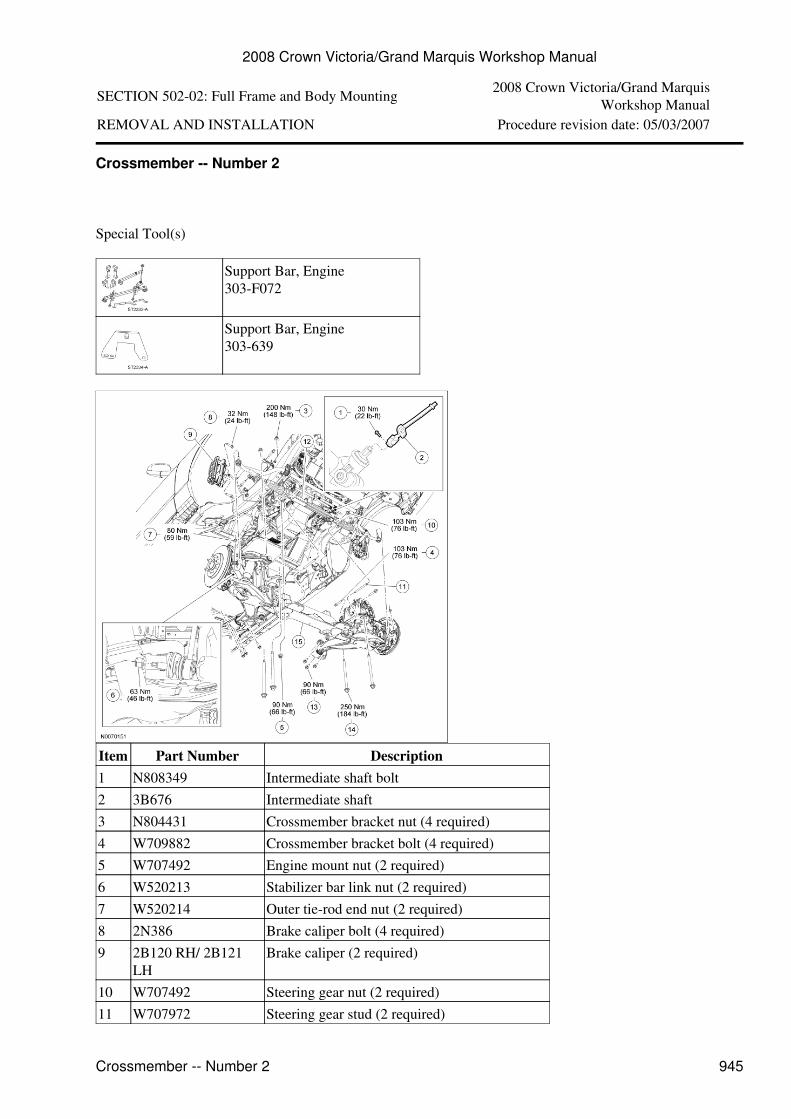
Crossmember -- Number 2
Special Tool(s)
Support Bar, Engine303-F072
Support Bar, Engine303-639
Item Part Number Description1 N808349 Intermediate shaft bolt2 3B676 Intermediate shaft3 N804431 Crossmember bracket nut (4 required)4 W709882 Crossmember bracket bolt (4 required)5 W707492 Engine mount nut (2 required)6 W520213 Stabilizer bar link nut (2 required)7 W520214 Outer tie-rod end nut (2 required)8 2N386 Brake caliper bolt (4 required)9 2B120 RH/ 2B121
LHBrake caliper (2 required)
10 W707492 Steering gear nut (2 required)11 W707972 Steering gear stud (2 required)
2008 Crown Victoria/Grand Marquis Workshop Manual
Crossmember -- Number 2 945
12 3504 Steering gear13 W708601 Lower control arm rear mounting bolt (6
required)14 W707968 No. 2 crossmember bolt (4 required)15 5C145 No. 2 crossmemberRemoval
NOTICE: Suspension fasteners are critical parts because they affect the performance of vitalcomponents and systems and their failure can result in major repair expense. A new part with the samepart number must be installed if installation is necessary. Do not use a new part of lesser quality orsubstitute design. Torque values must be used as specified during reassembly to make sure of correctretention of these parts.
Remove the generator. For additional information, refer to Section 414-02 .1.
Remove the 3 pin-type retainers and the radiator sight shield.2.
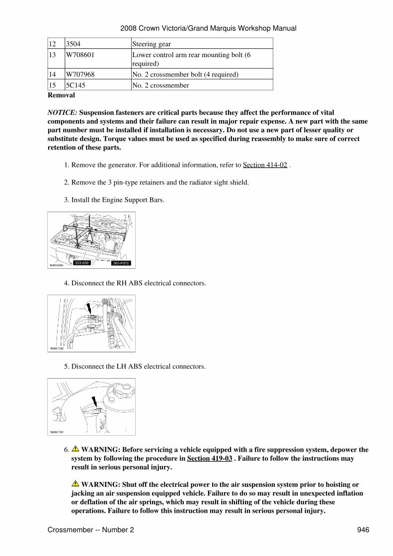
Install the Engine Support Bars.3.
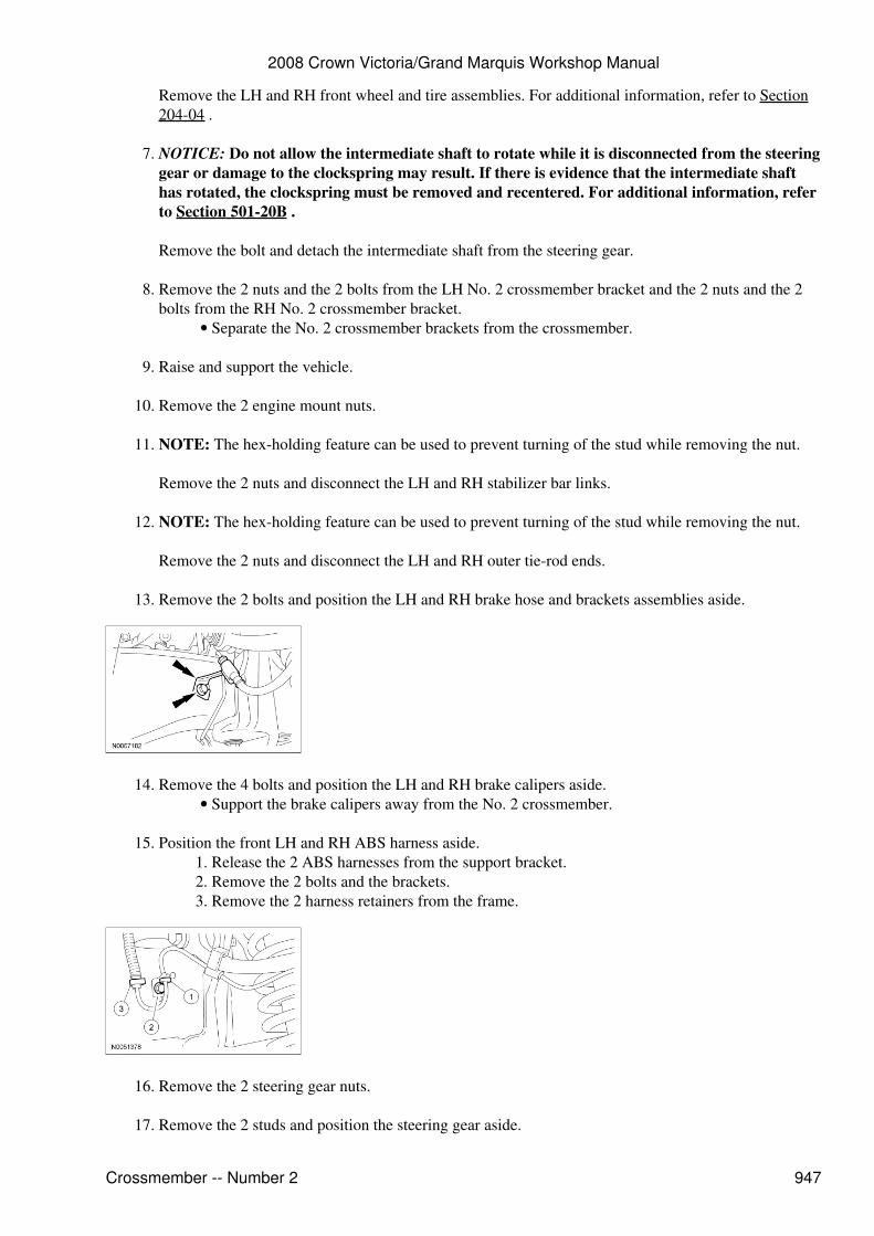
Disconnect the RH ABS electrical connectors.4.
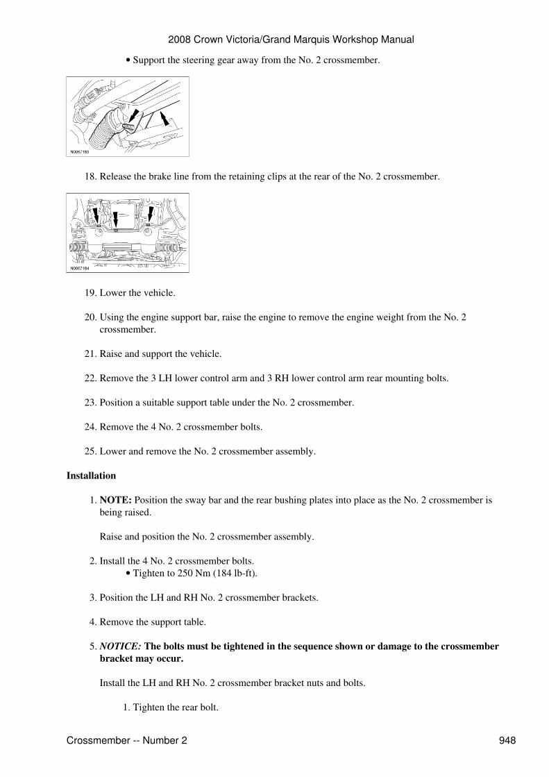
Disconnect the LH ABS electrical connectors.5.
WARNING: Before servicing a vehicle equipped with a fire suppression system, depower thesystem by following the procedure in Section 419-03 . Failure to follow the instructions mayresult in serious personal injury.
WARNING: Shut off the electrical power to the air suspension system prior to hoisting orjacking an air suspension equipped vehicle. Failure to do so may result in unexpected inflationor deflation of the air springs, which may result in shifting of the vehicle during theseoperations. Failure to follow this instruction may result in serious personal injury.
6.
2008 Crown Victoria/Grand Marquis Workshop Manual
Crossmember -- Number 2 946
Remove the LH and RH front wheel and tire assemblies. For additional information, refer to Section204-04 .
NOTICE: Do not allow the intermediate shaft to rotate while it is disconnected from the steeringgear or damage to the clockspring may result. If there is evidence that the intermediate shafthas rotated, the clockspring must be removed and recentered. For additional information, referto Section 501-20B .
Remove the bolt and detach the intermediate shaft from the steering gear.
7.
Remove the 2 nuts and the 2 bolts from the LH No. 2 crossmember bracket and the 2 nuts and the 2bolts from the RH No. 2 crossmember bracket.
Separate the No. 2 crossmember brackets from the crossmember.•
8.
Raise and support the vehicle.9.
Remove the 2 engine mount nuts.10.
NOTE: The hex-holding feature can be used to prevent turning of the stud while removing the nut.
Remove the 2 nuts and disconnect the LH and RH stabilizer bar links.
11.
NOTE: The hex-holding feature can be used to prevent turning of the stud while removing the nut.
Remove the 2 nuts and disconnect the LH and RH outer tie-rod ends.
12.
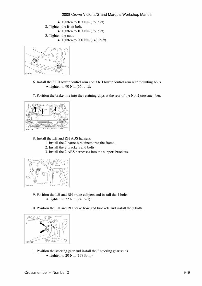
Remove the 2 bolts and position the LH and RH brake hose and brackets assemblies aside.13.
Remove the 4 bolts and position the LH and RH brake calipers aside.Support the brake calipers away from the No. 2 crossmember.•
14.
Position the front LH and RH ABS harness aside.Release the 2 ABS harnesses from the support bracket.1. Remove the 2 bolts and the brackets.2. Remove the 2 harness retainers from the frame.3.
15.
Remove the 2 steering gear nuts.16.
Remove the 2 studs and position the steering gear aside.17.
2008 Crown Victoria/Grand Marquis Workshop Manual
Crossmember -- Number 2 947
Support the steering gear away from the No. 2 crossmember.•
Release the brake line from the retaining clips at the rear of the No. 2 crossmember.18.
Lower the vehicle.19.
Using the engine support bar, raise the engine to remove the engine weight from the No. 2crossmember.
20.
Raise and support the vehicle.21.
Remove the 3 LH lower control arm and 3 RH lower control arm rear mounting bolts.22.
Position a suitable support table under the No. 2 crossmember.23.
Remove the 4 No. 2 crossmember bolts.24.
Lower and remove the No. 2 crossmember assembly.25.
Installation
NOTE: Position the sway bar and the rear bushing plates into place as the No. 2 crossmember isbeing raised.
Raise and position the No. 2 crossmember assembly.
1.
Install the 4 No. 2 crossmember bolts.Tighten to 250 Nm (184 lb-ft).•
2.
Position the LH and RH No. 2 crossmember brackets.3.
Remove the support table.4.
NOTICE: The bolts must be tightened in the sequence shown or damage to the crossmemberbracket may occur.
Install the LH and RH No. 2 crossmember bracket nuts and bolts.
Tighten the rear bolt.1.
5.
2008 Crown Victoria/Grand Marquis Workshop Manual
Crossmember -- Number 2 948
Tighten to 103 Nm (76 lb-ft).♦ Tighten the front bolt.
Tighten to 103 Nm (76 lb-ft).♦ 2.
Tighten the nuts.Tighten to 200 Nm (148 lb-ft).♦
3.
Install the 3 LH lower control arm and 3 RH lower control arm rear mounting bolts.Tighten to 90 Nm (66 lb-ft).•
6.
Position the brake line into the retaining clips at the rear of the No. 2 crossmember.7.
Install the LH and RH ABS harness.Install the 2 harness retainers into the frame.1. Install the 2 brackets and bolts.2. Install the 2 ABS harnesses into the support brackets.3.
8.
Position the LH and RH brake calipers and install the 4 bolts.Tighten to 32 Nm (24 lb-ft).•
9.
Position the LH and RH brake hose and brackets and install the 2 bolts.10.
Position the steering gear and install the 2 steering gear studs.Tighten to 20 Nm (177 lb-in).•
11.
2008 Crown Victoria/Grand Marquis Workshop Manual
Crossmember -- Number 2 949
Install the 2 steering gear nuts.Tighten to 103 Nm (76 lb-ft).•
12.
NOTE: The hex-holding feature can be used to prevent turning of the stud while installing the nut.
Position the LH and RH stabilizer bar links and install the 2 nuts.
Install new nuts.• Tighten to 63 Nm (46 lb-ft).•
13.
NOTE: The hex-holding feature can be used to prevent turning of the stud while installing the nut.
Position the LH and RH tie-rod ends and install the 2 nuts.
Install new nuts.• Tighten to 80 Nm (59 lb-ft).•
14.
Lower the vehicle.15.
Connect the intermediate shaft to the steering gear and install the bolt.Tighten to 30 Nm (22 lb-ft).•
16.
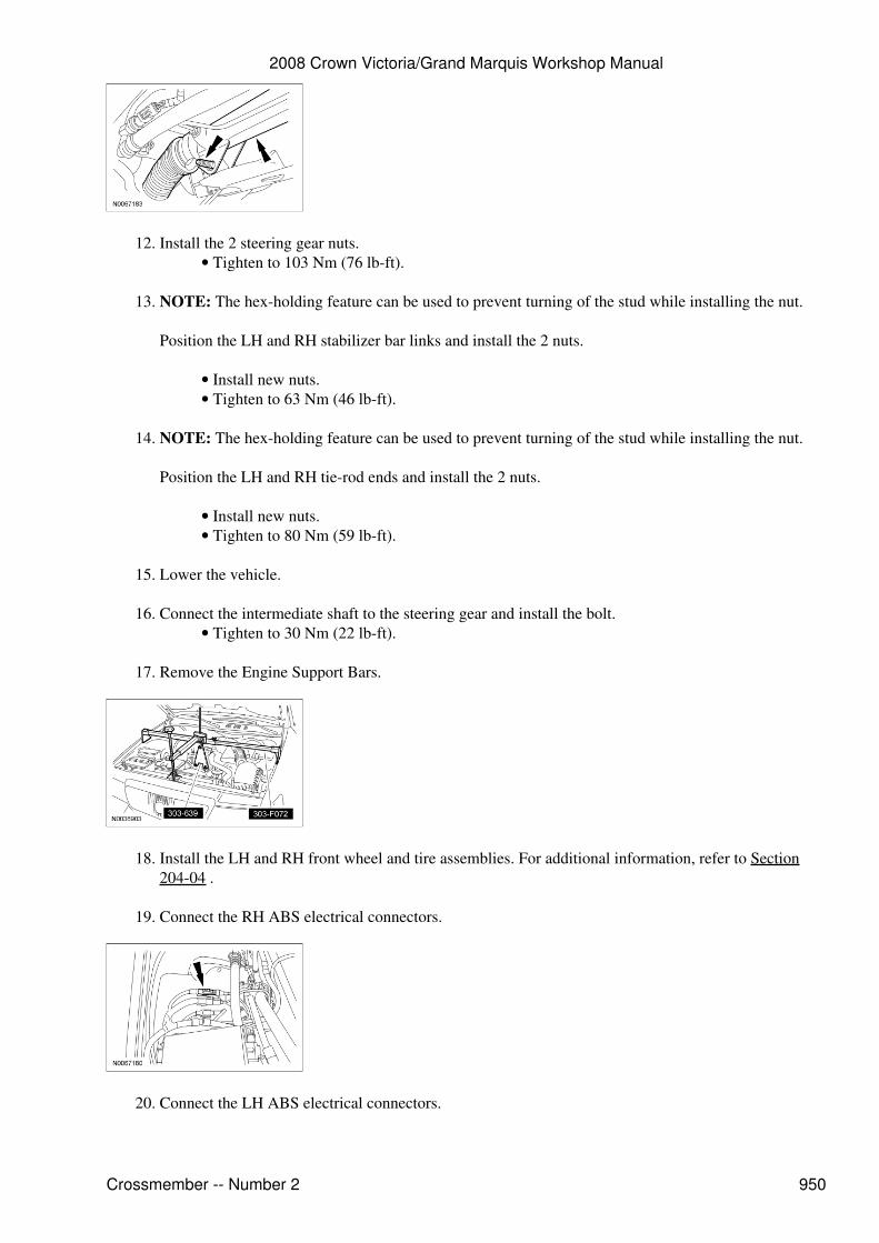
Remove the Engine Support Bars.17.
Install the LH and RH front wheel and tire assemblies. For additional information, refer to Section204-04 .
18.
Connect the RH ABS electrical connectors.19.
Connect the LH ABS electrical connectors.20.
2008 Crown Victoria/Grand Marquis Workshop Manual
Crossmember -- Number 2 950