Embed Size (px)
Citation preview

MIT OpenCourseWare http://ocw.mit.edu 2.007 Design and Manufacturing ISpring 2009
For information about citing these materials or our Terms of Use, visit: http://ocw.mit.edu/terms.
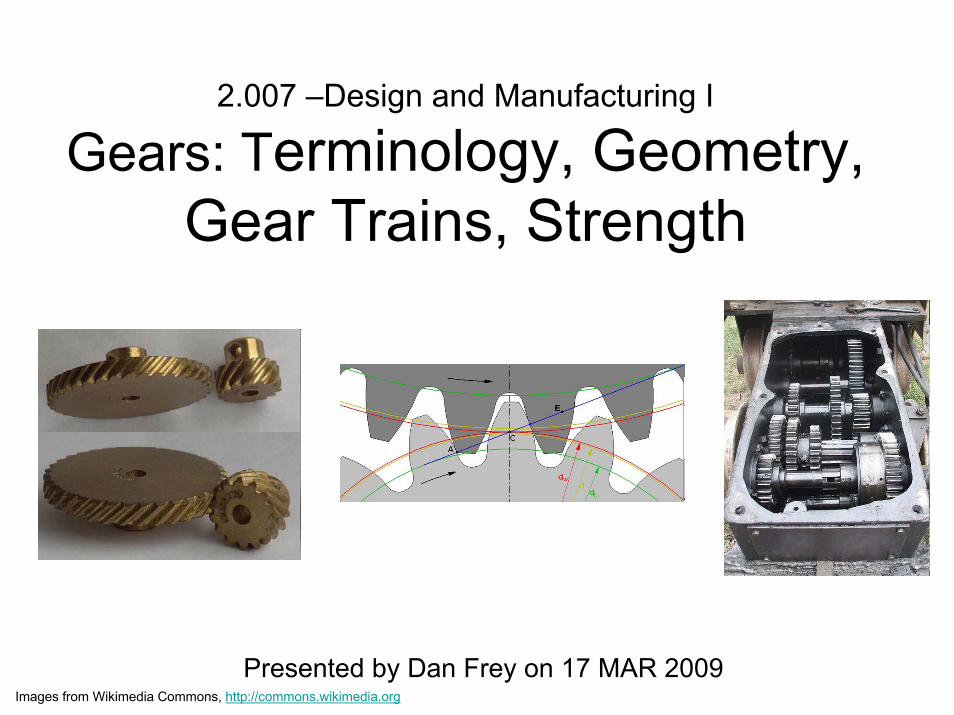
2.007 –Design and Manufacturing I
Gears: Terminology, Geometry, Gear Trains, Strength
Presented by Dan Frey on 17 MAR 2009Images from Wikimedia Commons, http://commons.wikimedia.org

Today’s Agenda
• Distribute homework #3• Gears
– Applications– Types– Terminology / nomenclature– Congugate action – Involute curve– Analysis & design

Applications of Gears
Sobel, Dava, Longitude
Images removed due to copyright restrictions. Please see http://mossmotors.com/Graphics/Products/Schematics/SPM-027.gifhttp://www.nmm.ac.uk/collections/displayRepro.cfm?reproID=A6263
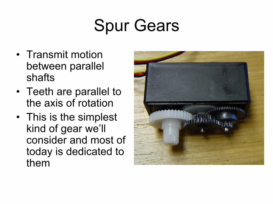
Spur Gears• Transmit motion
between parallel shafts
• Teeth are parallel to the axis of rotation
• This is the simplest kind of gear we’ll consider and most of today is dedicated to them

Gear Terminology
Source: Fig. 1.1 in “Gears.” Design and Application of Small Standardized components Data Book 757. Stock Drive Products, 1983. Accessed September 18, 2009. Courtesy of Stock Drive Products/Sterling Instrument.
Diametral pitch (teeth per inch)# of teeth on a gear with a
1 inch pitch diameter
Easily confused

Other Types of Gears
Helical Bevel
RackWorm
Courtesy OSHA.
Images from Wikimedia Commons, http://commons.wikimedia.org
Image courtesy of perlmonger on Flickr.
Early Gears
Roman watermills at Barbegal300AD
Application for powering textile machinery18th century
Drawings of waterwheels and gears removed due to copyright restrictions.
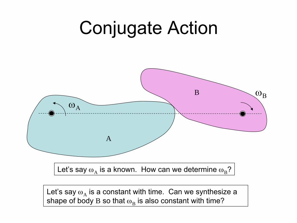
Conjugate Action
ωΑ
A
B ωΒ
Let’s say ωA is a known. How can we determine ωB?
Let’s say ωA is a constant with time. Can we synthesize a shape of body B so that ωB is also constant with time?

Pitch Point
ωΑ
A
B ωΒ
What is the pitch point?
What is the line of action?
What are the relationships among these?
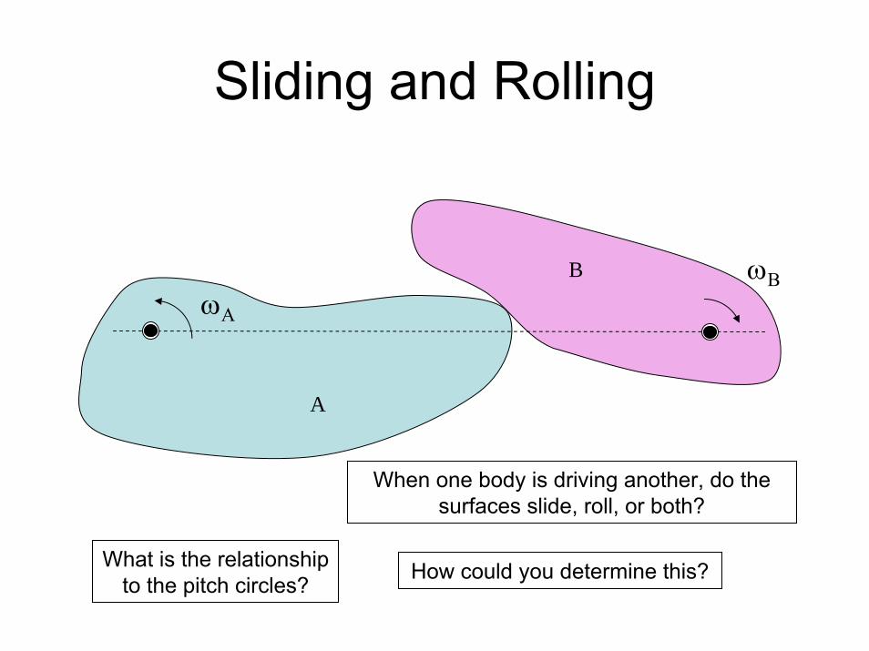
Sliding and Rolling
ωΑ
A
B ωΒ
What is the relationship to the pitch circles?
When one body is driving another, do the surfaces slide, roll, or both?
How could you determine this?
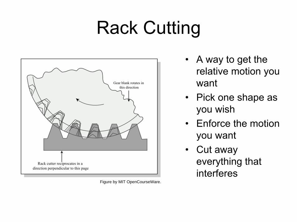
Rack Cutting• A way to get the
relative motion you want
• Pick one shape as you wish
• Enforce the motion you want
• Cut away everything that interferes
Gear blank rotates in this direction
Rack cutter reciprocates in a direction perpendicular to this page
Figure by MIT OpenCourseWare.
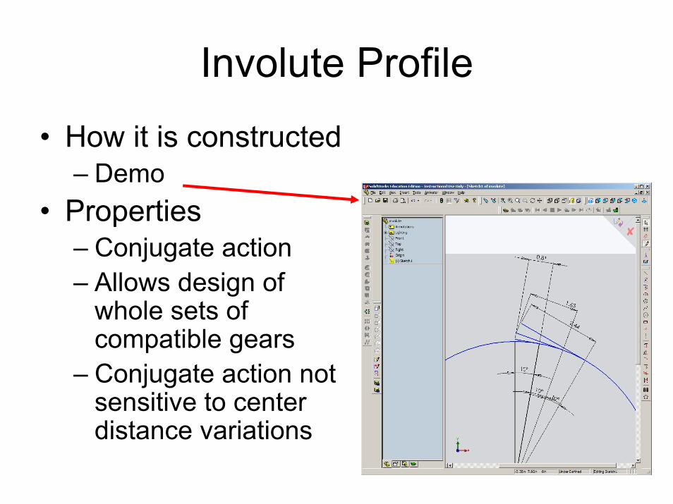
Involute Profile
• How it is constructed– Demo
• Properties– Conjugate action– Allows design of
whole sets of compatible gears
– Conjugate action not sensitive to center distance variations

From Shigley and Mischke
This geometry is not an involute.
More Gear Terminology
Image removed due to copyright restrictions. Please see http://commons.wikimedia.org/wiki/File:Gear_words.png
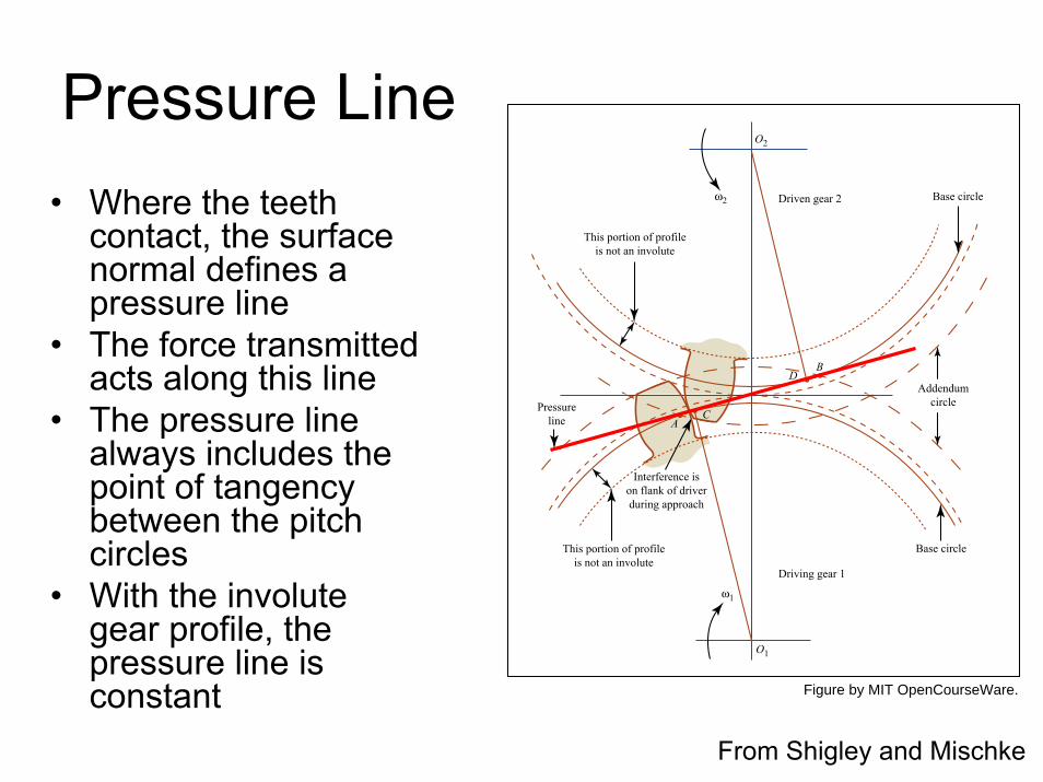
Pressure Line• Where the teeth
contact, the surface normal defines a pressure line
• The force transmitted acts along this line
• The pressure line always includes the point of tangency between the pitch circles
• With the involutegear profile, the pressure line is constant
From Shigley and Mischke
Base circle
Base circle
AddendumcirclePressure
line
This portion of profileis not an involute
This portion of profileis not an involute
Interference ison flank of driverduring approach
CA
DB
Driven gear 2
Driving gear 1
O2
O1
ω2
ω1
Figure by MIT OpenCourseWare.

Gear Terminology
“Line of action” & “pressure line” & “generating line”
are all synonymous
Source: Fig. 1.1 in “Gears.” Design and Application of Small Standardized components Data Book 757. Stock Drive Products, 1983. Accessed September 18, 2009. Courtesy of Stock Drive Products/Sterling Instrument.

Pressure Angle• The pressure line
acts at some angle to the tangent of the pitch circles
• This angle can be chosen by the designer
• It affects– Separation forces– Tooth shape
From Shigley and Mischke
Figure by MIT OpenCourseWare.
Base circle
Base circle
AddendumcirclePressure
line
This portion of profileis not an involute
This portion of profileis not an involute
Interference ison flank of driverduring approach
CA
DB
Driven gear 2
Driving gear 1
O2
O1
ω2
ω1
Pressure angle

Concept Question
1. << 0.32. About 0.33. About 0.54. >> 0.5
A pair of gears are mated. One is driven at a set torque, the other is regulated at a set speed. The gears are the ones circled. What is the ratio of the separation forces and the total force on the bearing?
Courtesy of W. M. Berg, Inc. Used with permission.

Contact Ratio
addendum of gear
addendum of pinion
pitch circlearc of action
zone of action
pressure line
contact ratio = length of arc of action / pitch = average number of teeth engaged

Interference
From Shigley and Mischke
Base circle
Base circle
AddendumcirclePressure
line
This portion of profileis not an involute
This portion of profileis not an involute
Interference ison flank of driverduring approach
CA
DB
Driven gear 2
Driving gear 1
O2
O1
ω2
ω1
Figure by MIT OpenCourseWare.

Backlash
Courtesy of W. M. Berg, Inc. Used with permission.

Gear Selection
• Pitch• Face width• Material• Pressure angle• # of teeth• Hub style, bore, etc.
Courtesy of W. M. Berg, Inc. Used with permission.

• You call up the number 1-800-232-BERG and ask that, for a special application, you want a 48 pitch spur gear, but with a pitch dia of 0.32 inches. They will probably say:1. OK, no problem2. OK, but it will cost a
lot3. No, this is not
technically possible
Courtesy of W. M. Berg, Inc. Used with permission.

• You call up the number 1-800-232-BERG and ask that, for a special application, you want a 48 pitch spur gear, but with a pitch dia of half the smallest one in the catalog. They will probably say:1. OK, no problem2. OK, but it will cost a lot3. OK, but it will be weak4. No, this is not
technically possible
Courtesy of W. M. Berg, Inc. Used with permission.

Ways Gears Fail
Exceed static yield stress in bendingExceed endurance limit in bending
Exceed endurance limit in contact stress
Images removed due to copyright restrictions. Please see http://materials.open.ac.uk/mem/mem_mf6.htmhttp://www.hghouston.com/x/39_gearpit.html “pitting”
“stripping”
Image courtesy of deltaMike at Flickr.

Stress in Gears
Image removed due to copyright restrictions. Please see p. 1 in http://courses.washington.edu/mengr356/daly/Gear_stress.pdf

A Beam in Bending
26
/ FtlW
cIM t==σ
FWt
t
l
Figure by MIT OpenCourseWare.

Concept Question• In selecting a gear of one inch pitch
diameter, we are choosing between 48 and 24 pitch gear teeth. The effect on torque that can be transmitted before bending failure of the teeth is
1. Around a factor of 102. Around a factor of 43. Around a factor of 24. Less than a factor of 2
t
x
a
WrW
Wt
rf
l
Figure by MIT OpenCourseWare.

Strength of Gears
• Any good catalog will have a formula and tables
• What factors must enter the equation?–––
• Where do the teeth wear the most?
Courtesy of W. M. Berg, Inc. Used with permission.
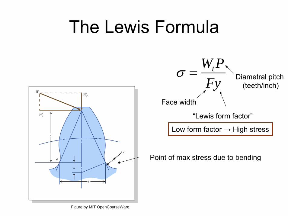
The Lewis Formula
FyPWt=σ
Point of max stress due to bending
“Lewis form factor”
Low form factor → High stress
Diametral pitch (teeth/inch)
Face width
t
x
a
WrW
Wt
rf
l
Figure by MIT OpenCourseWare.

Or Use a Canned Tool
Please see “Spur Gear Tooth Strength” at http://www.wmberg.com/tools/

Discussion Questions• I glued the third stage teeth of this servo together• Now I will apply a load to the output shaft (up to 10lbs)• What’s going to happen?
Epoxy applied liberally here
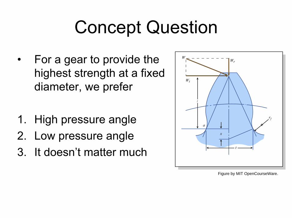
Concept Question
• For a gear to provide the highest strength at a fixed diameter, we prefer
1. High pressure angle2. Low pressure angle3. It doesn’t matter much t
x
a
WrW
Wt
rf
l
Figure by MIT OpenCourseWare.
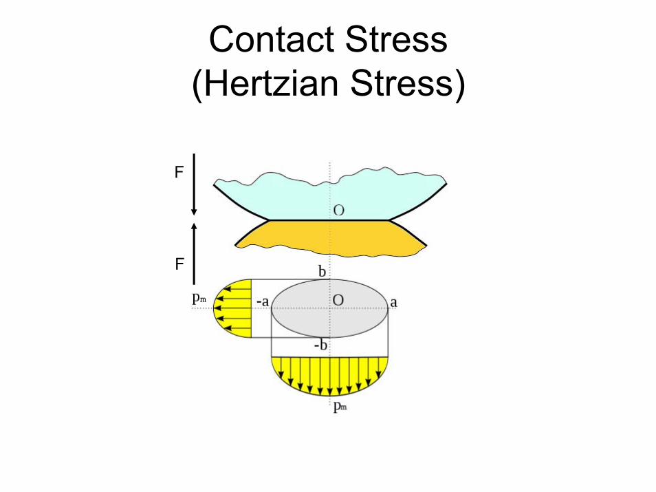
Contact Stress(Hertzian Stress)
F
F

Contact StressQuantitative Characterization
0 0.5 1 1.5 2 2.5 30
0.2
0.4
0.6
0.8
1
σz z d1, d2,( )pmax d1 d2,( )σy z d1, d2,( )pmax d1 d2,( )σx z d1, d2,( )pmax d1 d2,( )τyz z d1, d2,( )pmax d1 d2,( )τxz z d1, d2,( )pmax d1 d2,( )
zb d1 d2,( )
b d1 d2,( ) 2 F⋅π l⋅
1 ν12
−⎛⎝
⎞⎠
E1
1 ν22
−
E2+
1d1
1d2
+⋅:= pmax d1 d2,( ) 2 F⋅
π b d1 d2,( )⋅ l⋅:=
F
F

Simple Gear Trains
• A “simple” gear train has only one gear on each shaft
• How does this arrangement behave?
ω1

Compound Gear Trains
• A “compound”gear train has at least one shaft with multiple gears
• How does this arrangement behave?
Image from Wikimedia Commons, http://commons.wikimedia.org

Manual Transmissions
If you find just two axles in a machine, does that mean there are just two stages?
Image from Wikimedia Commons, http://commons.wikimedia.org. Please see http://mossmotors.com/Graphics/Products/Schematics/SPM-025.gif

Discussion Questions
• Are there any disadvantage to a helical gear as compared to a spur gear?
• How can the disadvantages be remedied?
• Is a helical gear set stronger than a spur gear of the same diameter, pitch, face width, & material?
Image from Wikimedia Commons, http://commons.wikimedia.org

Concept Question
1. Pitch rises, face width rises
2. Pitch rises, face width falls
3. Pitch falls, face width rises
4. Pitch falls, face width falls
A compound gear train is formed of eight gears. As we proceed from the pinion on the electric motor to the gear on the output shaft, how do the pitch and face width vary?
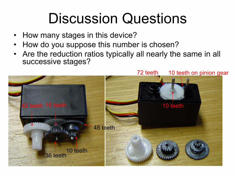
Discussion Questions• How many stages in this device?• How do you suppose this number is chosen?• Are the reduction ratios typically all nearly the same in all
successive stages?10 teeth on pinion gear72 teeth
10 teeth
36 teeth10 teeth
48 teeth
16 teeth42 teeth

Differentials• Allows shafts
to move at different speeds
• Applies same torque to both
• Slippage problem
http://static.howstuffworks.com/flash/differential.swf
Image removed due to copyright restrictions. Please see http://mossmotors.com/Graphics/Products/Schematics/SPM-027.gif

Next Steps• Begin Homework #3• Next lecture Thursday 19 March
– CAD case study• Spring break• Lecture Tuesday 31 March
– More gears, and also springs• HW#3 due 7 April• Quiz #2 on 16 April• Impounding week 29 April to 1 May

Planetary Gear Trains
• One or more of the gear axes are allowed to rotate
• aka “epicyclic”• Used in
– Power tools– Automatic
transmissions– Gear boxes
Courtesy NASA.
Please also see http://commons.wikimedia.org/wiki/File:Epicyclic_carrier_locked.png
http://i.i.com.com/cnwk.1d/i/ss/2007/0828_Driving_it/DSG_440.jpg

Analysis of Planetary Gear Trains
Sun gear
20T
30T
80T
Arm
Planetgear
Ring gear
Figure by MIT OpenCourseWare.

Name That GearWhat type of worm gear set
is this?1) Single-enveloping,
single threaded 2) Single-enveloping,
multi-threaded 3) Double enveloping
single threaded worm gear
4) Double enveloping multi- threaded

Follow up
What is the reduction ratio of this gear set?
1) 10:1 2) 20:1 3) 40:14) 80:1
40 teeth