Embed Size (px)
Citation preview

8/8/2019 2006 Stair Irc Screen
http://slidepdf.com/reader/full/2006-stair-irc-screen 1/16
Visual Interpretation Of The
I N T E R N A T I O N A L
R E S I D E N T I A L
CO D E
2006 STAIR BUILDING CODE
Portions of this document reproduce sections from the2006 International Residential Code, International Code Council, Falls Church, Virginia.
Reproduced with permission. All rights reserved.

8/8/2019 2006 Stair Irc Screen
http://slidepdf.com/reader/full/2006-stair-irc-screen 2/16
If you nd this document to be of signicant value, then you will nd it equally benecial toassociate with a member of the Stairway Manufacturer’s Association (SMA). The members
of the SMA have taken on the task of inuencing the development of responsible and
functional building codes. They are the very individuals effectively communicating consistent
interpretation of each stair code. A resulting product of their effort is this Visual Interpretation.
SMA members know their craft of Stair Design and Construction and they know Building
Codes. You are encouraged to contact a member of the SMA before you begin your next
stairway project.
If your work is related to stairs and you can prescribe to the ethics and quality standards
of the SMA you may qualify for membership. To learn more about the SMA go to
www.stairways.org, or contact us at [email protected].
The Stairway Manufacturers Association publishes visual interpretations of Building
Codes to be accurate pictorial descriptive material void of editorial comment to aid in
the understanding of the written text. We provide this document as a learning tool to aid
designers, builders, homeowners, building ofcials, stair builders, and others in the shelter
industry to accurately and consistently interpret the building code related to stairways.
The SMA has participated in the model code development process since 1988. We supportthe International Code Council’s development process through our membership and are
recognized and respected for our responsible efforts at code reform and interpretation in
addition to our trade and industry experience that we bring to the table. This experience and
reputation is an asset to our continued efforts to provide safe stairways and reduce stairway
accidents while allowing freedom of design, and aesthetic properties of preference.
In addition to our experience in the code development process we use the commentaries
published by the International Code Council as a resource for each visual interpretation.
The SMA wishes to thank the ICC for their permission to print portions of the IRC and infull recognition of our responsibility to educate and inform we invite your feedback and
comments.
This document is provided electronically at no cost to those who wish to print it in whole
from www.stairways.org. It is not to be copied or used in part or in any other publication.
Printed copies are available to SMA members for the cost of shipping.
The Stair IndustryDedicated to Safety & Quality

8/8/2019 2006 Stair Irc Screen
http://slidepdf.com/reader/full/2006-stair-irc-screen 3/16Stairway Manufacturers’ Association Interpretation of IRC 2006 • www.stairways.org • Page No. 3
MINIMUM 36” CLEAR WIDTH
SECTION R311.5 STAIRWAYS
R311.5.1 Width.Stairways shall not be less than 36 inches (914 mm) inclear width at all points above the permitted handrailheight and below the required headroom height.PHOTO 1. Handrails shall not project more than 4.5inches (114 mm) on either side of the stairway PHOTO
2 and the minimum clear width of the stairway at and
below the handrail height, including treads and landings,shall not be less than 31.5 inches (787 mm) where ahandrail is installed on one side and 27 inches (698 mm)where handrails are provided on both sides PHOTO 3.
Exception: The width of spiral stairways shall be inaccordance with Section R311.5.8.See PHOTO 35 on page 12.
MAXIMUMHANDRAILPROJECTION
PHOTO 2
PHOTO 1
4 - 1 / 2 ”
8/8/2019 2006 Stair Irc Screen
http://slidepdf.com/reader/full/2006-stair-irc-screen 4/16Stairway Manufacturers’ Association Interpretation of IRC 2006 • www.stairways.org • Page No. 4
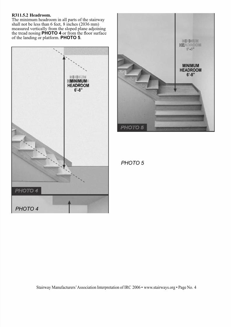
R311.5.2 Headroom.The minimum headroom in all parts of the stairwayshall not be less than 6 feet, 8 inches (2036 mm)measured vertically from the sloped plane adjoiningthe tread nosing PHOTO 4 or from the oor surfaceof the landing or platform. PHOTO 5.
MINIMUMHEADROOM
6’-8”
MINIMUMHEADROOM
6’-8”
PHOTO 4
PHOTO 5
8/8/2019 2006 Stair Irc Screen
http://slidepdf.com/reader/full/2006-stair-irc-screen 5/16Stairway Manufacturers’ Association Interpretation of IRC 2006 • www.stairways.org • Page No. 5
MAXIMUMRISE7-3/4”
7-3/8”
7-5/8”
7-5/8”
7-5/8”
7-3/4”
SAMPLE STAIRIS WITHIN
ACCEPTABLECODE LIMITS
GREATEST RISE 7-3/4”SMALLEST RISE – 7-3/8”
= 3/8”
SAMPLE STAIRIS WITHIN
ACCEPTABLECODE LIMITS
GREATEST TREAD DEPTH 10-3/8SMALLEST TREAD DEPTH – 10”
= 3/810-1/8”
10-3/8”
10”
10”
10”
MINIMUM DEPTH10”
PHOTO 8
PHOTO 9
PHOTO 7
PHOTO 6
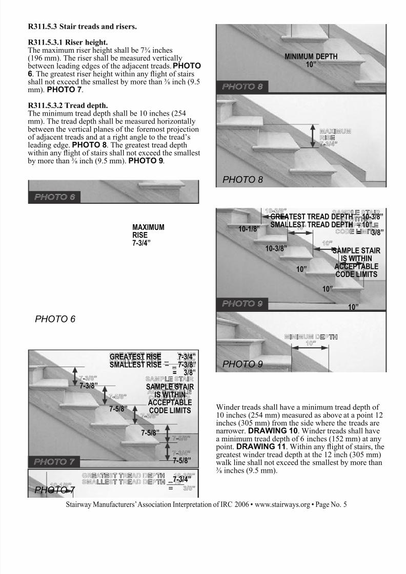
R311.5.3 Stair treads and risers.
R311.5.3.1 Riser height.The maximum riser height shall be 7 inches(196 mm). The riser shall be measured vertically between leading edges of the adjacent treads. PHOTO
6. The greatest riser height within any ight of stairsshall not exceed the smallest by more than inch (9.5mm). PHOTO 7.
R311.5.3.2 Tread depth.The minimum tread depth shall be 10 inches (254mm). The tread depth shall be measured horizontally between the vertical planes of the foremost projectionof adjacent treads and at a right angle to the tread’sleading edge. PHOTO 8. The greatest tread depthwithin any ight of stairs shall not exceed the smallest by more than inch (9.5 mm). PHOTO 9.
Winder treads shall have a minimum tread depth of 10 inches (254 mm) measured as above at a point 12inches (305 mm) from the side where the treads arenarrower. DRAWING 10. Winder treads shall havea minimum tread depth of 6 inches (152 mm) at any point. DRAWING 11. Within any ight of stairs, thgreatest winder tread depth at the 12 inch (305 mm)walk line shall not exceed the smallest by more than inches (9.5 mm).

8/8/2019 2006 Stair Irc Screen
http://slidepdf.com/reader/full/2006-stair-irc-screen 6/16Stairway Manufacturers’ Association Interpretation of IRC 2006 • www.stairways.org • Page No. 6
DRAWING 11
ALTERNATE WINDER TREAD DESIGNS
10”MINIMUMWIDTH ATWALKLINE
MINIMUM INSIDEWIDTH 6”
12”
WALKLINE
DRAWING 10
12”
WINDER - A tread with non-parallel edges (as dened in Chapter 2 - IRC, IBC).

8/8/2019 2006 Stair Irc Screen
http://slidepdf.com/reader/full/2006-stair-irc-screen 7/16Stairway Manufacturers’ Association Interpretation of IRC 2006 • www.stairways.org • Page No. 7
R311.5.3.3 Prole.The radius of curvature at the leading edge of thetread shall be no greater than 9/16 inch (14.3 mm).PHOTO 12. A nosing not less than inch (19mm) but not more than 1 inches (32 mm) shall be provided on stairways with solid risers. PHOTO 13.The greatest nosing projection shall not exceed thesmallest nosing projection by more than inch (9.5mm) between two stories, including the nosing at thelevel of oors and landings. PHOTO 14. Bevelingof nosing shall not exceed inch (12.7 mm).PHOTO 15. Risers shall be vertical or sloped fromthe underside of the leading edge of the tread aboveat an angle not more than 30 (0.51 rad) degrees fromthe vertical. PHOTO 16. Open risers are permitted, provided that the opening between treads does not permit the passage of a 4-inch diameter (102 mm)sphere. PHOTO 17.
Exceptions: 1. A nosing is not required where thetread depth is a minimum of 11 inches(279 mm).
2. The opening between adjacent treads isnot limited on stairs with a total rise of 30inches (762 mm) or less. PHOTO 17.
1/2” MAXIMUM BEVEL
SLOPE OF RISER MAYNOT EXCEED 30°
30°
RADIUS OFCURVATURE
CANNOT EXCEED9/16”
NOSING PROJECTIONMAY NOT VARY MORETHAN 3/8”
TREAD OVERHANGMINIMUM = 3/4”
MAXIMUM = 1-1/4”
NOTE: SEEEXCEPTION 1 ABOVE
PHOTO 16
PHOTO 15
PHOTO 17 PHOTO 14
PHOTO 13
PHOTO 12
MODIFIED TO RESTRICTPASSAGE OF A 4” SPHERE
IF TOTAL RISE IS LESSTHAN 30”, 4” SPHERE
RULE DOES NOT APPL

8/8/2019 2006 Stair Irc Screen
http://slidepdf.com/reader/full/2006-stair-irc-screen 8/16Stairway Manufacturers’ Association Interpretation of IRC 2006 • www.stairways.org • Page No. 8
R311.5.4 Landings for Stairways.There shall be a oor or landing at the top and bottom of each stairway.
Exception: A oor or landing is not required atthe top of an interior ight of stairs,including stairs in an enclosed garage, provided a door does not swing over the stairs.
A ight of stairs shall not have a vertical risegreater than 12 feet (3658 mm) between oor levelsor landings.The width of each landing shall not be less thanthe stairway served. Every landing shall havea minimum dimension of 36 inches (914 mm)measured in the direction of travel. DRAWING 18.
PHOTO 19
NOT MORE THAN 1 UNIT VERTICAL IN48 UNITS HORIZONTAL (2% SLOPE)
2%
2%
MAXIMUM SLOPE10” TREAD DEPTH + 1-1/4” NOSING = .2344”
R311.5.5 Stairway walking surface.The walking surface of treads and landings of stairways shall be sloped no steeper than one unitvertical in 48 inches horizontal (2-percent slope).PHOTO 19.
R311.5.6.1 Height. Handrailheight, measured vertically fromthe sloped plane adjoining thetread nosing, or nish surfaceof ramp slope, shall be not less
than 34 inches (864 mm) and notmore than 38 inches (965 mm).PHOTO 21.
RAKE RAILHEIGHT
MIN. = 34”MAX. = 38”
PHOTO 21DRAWING 18
STAIRWIDTH=A
MINIMUM LANDINGWIDTH=A OR MORE
STAIRWIDTH=B
UPDOWN
DIRECTIONOF
TRAVEL
MINIMUMLANDINGWIDTH=BOR MORE

8/8/2019 2006 Stair Irc Screen
http://slidepdf.com/reader/full/2006-stair-irc-screen 9/16Stairway Manufacturers’ Association Interpretation of IRC 2006 • www.stairways.org • Page No. 9
R311.5.6.2 Continuity.Handrails for stairways shall be continuous for the full length of the ight, from a point directlyabove the top riser of the ight to a point directlyabove lowest riser of the ight. DRAWING 22
and PHOTO 23. Handrail ends shall be returnedPHOTO 24 or shall terminate in newel posts or safety terminals. Handrails adjacent to a wall shallhave a space of not less than 1 inches (38 mm)
between the wall and the handrails. PHOTO 25.
Exceptions: 1. Handrails shall be permitted to beinterrupted by a newel post at the turn.PHOTO 26.
2. The use of a volute, turnout, startingeasing or starting newel shall be alloweover the lowest tread. PHOTO 27.
HANDRAIL
ENDS SHALL BERETURNED
MINIMUMHANDRAIL
CLEARANCE
1-1/2”
TURNOUT
VOLUTE
STARTINGEASING
VOLUTES, TURNOUTSAND STARTING EASINGS
ARE ALLOWED OVERTHE LOWEST TREAD
HANDRAIL MAY BE INTERRUPTED BY A NEWEL
PHOTO 26
DRAWING 22
PHOTO 24
PHOTO 25
PHOTO 27
STARTING NEWEL
HANDRAIL MUSTBE CONTINUOUS
PHOTO 23
FLIGHT 2
FLIGHT 1

8/8/2019 2006 Stair Irc Screen
http://slidepdf.com/reader/full/2006-stair-irc-screen 10/16Stairway Manufacturers’ Association Interpretation of IRC 2006 • www.stairways.org • Page No. 10
3-1/4”
CIRCULAR
PHOTO 29
PHOTO 30
NON-CIRCULAR
R311.5.6.3 Handrail grip size.All required handrails shall be of one of the followingtypes or provide equivalent graspability. DRAWING
28.
DIAMETER
MINIMUM 1-1/4”MAXIMUM 2”
MAX 2-1/4”
PERIMETERMINIMUM 4”
MAXIMUM 6-1/4”
MAX 2-1/4”
METAL
DRAWING 28
3-5/8”
1-3/4”
Profles other than Type I and Type II may be determinedto provide equivalent graspability.
1. Type I. Handrails with a circular cross sectionshall have an outside diameter of at least 1 inches(32 mm) and not greater than 2 inches (51 mm).PHOTO 29. If the handrail is not circular it shallhave a perimeter dimension of at least 4 inches (102mm) and not greater than 6 inches (160 mm) with amaximum cross section of dimension of 2 inches(57 mm). PHOTO 30.

8/8/2019 2006 Stair Irc Screen
http://slidepdf.com/reader/full/2006-stair-irc-screen 11/16Stairway Manufacturers’ Association Interpretation of IRC 2006 • www.stairways.org • Page No. 11
R311.5.7 Illumination.All stairs shall be provided with illumination inaccordance with Section R303.6.
PERIMETER GREATERTHAN 6-1/4”
PHOTO 31
FINGERRECESS AREABOTH SIDES } }
TALLEST PORTION
PHOTO 33
TO A LEVEL NOTLESS THAN 1-3/4”
ACHIEVE 5/16”DEPTH
CONTINUED FORAT LEAST 3/8”
PHOTO 34
WIDTH ABOVE RECESS
MINIMUM 1-1/4”
MAXIMUM 2-3/4”
EDGE MINIMUMRADIUS 0.01”
PHOTO 32
TALLEST PORTION
WITHIN 7/8”OF WIDEST
PORTIONACHIEVE 5/16”
DEPTH
WITHIN 3/4”FINGER RECESSBEGINS
2. Type II. Handrails with a perimeter greater than6 inches (160mm) shall provide a graspable n-ger recess area on both sides of the prole. PHOTO
31. The nger recess shall begin within a distance of inch (19 mm) measured vertically from the tallest portion of the prole and achieve a depth of at least5/16 inch (8mm) within inch (22mm) below thewidest portion of the prole. PHOTO 32. Thisrequired depth shall continue for at least inch(10mm) to a level that is not less than 1 inches (45mm) below the tallest portion of the prole. PHOTO
33. The minimum width of the handrail above therecess shall be 1 inches (32 mm) to a maximum of 2 inches (70 mm). PHOTO 34. Edges shall have aminimum radius of 0.01 inches (0.25 mm). PHOTO
34.
1-3/4”

8/8/2019 2006 Stair Irc Screen
http://slidepdf.com/reader/full/2006-stair-irc-screen 12/16Stairway Manufacturers’ Association Interpretation of IRC 2006 • www.stairways.org • Page No. 12
R311.5.8.2 Bulkhead enclosure stairways.Stairways serving bulkhead enclosures, not part of the required building egress, providing access fromthe outside grade level to the basement shall beexempt from the requirements of Sections R311.4.3and R311.5 where the maximum height from the basement nished oor level to grade adjacent tothe stairway does not exceed 8 feet (2438 mm), andthe grade level opening to the stairway is covered
by a bulkhead enclosure with hinged doors or other approved means.
SECTION R312 GUARDS
R312.1 Guards.Porches, balconies, ramps or raised oor surfaceslocated more than 30 inches (762 mm) above the oor or grade below shall have guards not less than 36inches (914 mm) in height. Open sides of stairs with a
total rise of more than 30 inches (762 mm) above theoor or grade below shall have guards not less than34 inches (864 mm) in height measured verticallyfrom the nosing of the treads. PHOTO 36.
Porches and decks which are enclosed with insectscreening shall be equipped with guards where thewalking surface is located more than 30 inches (762mm) above the oor or grade below.
PHOTO 36
GUARDMINIMUM
34”
BALCONYGUARD
MINIMUM 36”
IF TOTAL RISEIS OVER 30”...
R311.5.8.1 Spiral Stairs.Spiral stairways are permitted, provided the minimumwidth shall be 26 inches (660 mm) with each tread
having a 7 inch (190 mm) minimum tread depth at12 inches from the narrower edge. All treads shall beidentical, and the rise shall be no more than 9 inches(241 mm). A minimum headroom of 6 feet, 6 inches(1982 mm) shall be provided. PHOTO 35.
DOWNCOUNTER
CLOCKWISE26”MIN.
12”
7-1/2” MIN.TREAD WIDTH
PHOTO 35
MINIMUMHEADROOM
6’-6”
9-1/2”MAXIMUM
RISE
R311.5.8 Special stairways.Circular stairways, spiral stairways, winders and bulkhead enclosure stairways shall comply with allrequirements of Section R311.5 except as specied below.

8/8/2019 2006 Stair Irc Screen
http://slidepdf.com/reader/full/2006-stair-irc-screen 13/16Stairway Manufacturers’ Association Interpretation of IRC 2006 • www.stairways.org • Page No. 13
MUST NOTALLOW
PASSAGE OF 4”SPHERE
MUST NOT
ALLOWPASSAGE OF6” SPHERE
PHOTO 37
PHOTO 38
R312.2 Guard opening limitations.Required guards on open sides of stairways, raisedoor areas, balconies and porches shall haveintermediate rails or ornamental closures which donot allow passage of a sphere 4 inches (102 mm) or more in diameter. PHOTO 37.
Exception: 1. The triangular openings formed by theriser, tread and bottom rail of a guard at
the open side of a stairway are permittedto be of such a size that a sphere 6 inches(152 mm) cannot pass through. PHOTO
38.2. Openings for required guards onthe sides of stair treads shall not allowa sphere 4 inches (107 mm) to passthrough. PHOTO 38.
MUST NOTALLOW
PASSAGE OF4-3/8” SPHERE

8/8/2019 2006 Stair Irc Screen
http://slidepdf.com/reader/full/2006-stair-irc-screen 14/16Stairway Manufacturers’ Association Interpretation of IRC 2006 • www.stairways.org • Page No. 14
CHAPTER 2
DEFINITIONS
R201.3 Terms Dened in other codes. Where terms are not dened in this code such terms shall havemeanings ascribed to them as in other code publications of the International Code Council.
Note: In order to assure a complete understanding in accordance with above we have listed all the stair related denitions from both the IRC and the IBC (International Building Code).
IRCSection R202 Denitions
GUARD. A building component or a system of building components located near the open sides of elevated walking surfaces that minimizes the possibility of a fall from the walking surface to a lower level.
HANDRAIL. A horizontal or sloping rail intended for grasping by the hand for guidance or support.
WINDER. A tread with nonparallel edges.
IBCSection 1002 Denitions
ALTERNATING TREAD DEVICE. A device that has a series of steps between 50 and 70 degrees(0.87 and 1.22 rad) from horizontal, usually attached to a center support rail in an alternating manner sothat the user does not have both feet on the same level at the same time.
GUARD. A building component or a system of building components located at or near the open sidesof elevated walking surfaces that minimizes the possibility of a fall from the walking surface to a lower level.
HANDRAIL. A horizontal or sloping rail intended for grasping by the hand for guidance or support.
NOSING. The leading edge of treads of stairs and of landings at the top of stairway ights.
SCISSOR STAIR. Two interlocking stairways providing two separate paths of egress located withinone stairwell enclosure.
STAIR. A change in elevation, consisting of one or more risers.
STAIRWAY. One or more ights of stairs, either exterior or interior, with the necessary landings and platforms connecting them, to form a continuous and uninterrupted passage from one level to another.
STAIRWAY, EXTERIOR. A stairway that is open on at least one side, except for required structuralcolumns, beams, handrails and guards. The adjoining open areas shall be either yards, courts or publicways. The other sides of the exterior stairway need not be open.
STAIRWAY, INTERIOR. A stairway not meeting the denition of an exterior stairway.
STAIRWAY, SPIRAL. A stairway having a closed circular form in its plan view with uniform section-shaped treads attached to and radiating from a minimum-diameter supporting column.
WINDER. A tread with nonparallel edges.
8/8/2019 2006 Stair Irc Screen
http://slidepdf.com/reader/full/2006-stair-irc-screen 15/16
�
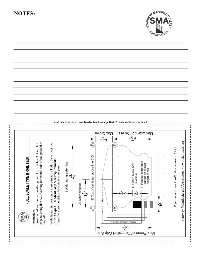
R e p r o d u c t i o n c h e c k : s o l i d l i n e m e a s u r e s 2 . 7
5 i n .
I n s t r u c t i o n s :
P o s i t i o n r a i l s e c t i o n w i t h w i d e s t p o i n t o f g r i p a t l i n e A B a n d l e f t
e d g e t o u c h i n g l i n e A C . K e e p i n g h o r i z o n t a l a x i s o f r a i l p a r a l l e l t o
l i n e A B .
W i t h t h e r a i l i n p o s i t i o n ,
i t m u s t p a s s t e s t s 1 ) t h r u 5 ) t o m e e t t h
e
R 3 1 5 . 2 T y p e I I H a n d r a i l G r i p S i z e r e q u i r e m e n t s .
I f p r o l e i s a s y m m e t r i c a l b o t h s i d e s m u s t p a s s .
F U L L S
C A L E
T Y P E
I I R A I L T E S T
NOTES:
cut on line and laminate for handy eld/desk reference tool
S t a i r w a y M a n u f a c t u
r e r s ’ A s s o c i a t i o n • w w w . s
t a i r w a y s . o r g

8/8/2019 2006 Stair Irc Screen
http://slidepdf.com/reader/full/2006-stair-irc-screen 16/16
THE MISSION OF THE SMA IS:
• To organize the varied elements of the stair industry into a leader in the code change process by actively participating at all levels.• To write standards that insure design andinstallation criteria meet or exceed theminimum standard set forth by the existingcode.
• To participate in design and product testing asto learn more about stair dynamics so thatsafety and aesthetics can coexist whileincidences of stair accidents are reduced.• To establish a central source that willdisseminate to the membership current and proposed code information impacting all facetsof stair building and millwork usage.• To protect the rights and interests of both theconsumer and the stair industry.The Stairway Manufacturers’ Association isdedicated to the prospect that safety andaesthetics, with respect to stairs, are not mutuallyexclusive....The SMA is a broad based industry associationfounded in 1988. Our members include stair
parts manufacturers, stair builders, installers,millwork distributors, dealers and interested building products professionals. We are anindustry organization run by industry people.Our primary focus is to represent the millwork industry to the building development groups atthe local, country, state and national levels.
Because the SMA represents the people who build, install and sell stair parts and stairways inthis country, it is our purpose to defend, test,evaluate and promote products and standards thatinsure safety in conjunction with growth and prosperity of our industry.
For more information about the associationor becoming a member either write, call or visit our website.The Stairway Manufacturers’ Association175 State Road East
Westminster, MA 01473Toll Free: 877-500-5759Website: www.stairways.orgEmail: [email protected]
IN SUPPORT OF THE
STAIR INDUSTRY!