Embed Size (px)
Citation preview
10-8212
Advanced Engine Management Inc. 2205 126th Street, Unit A
Hawthorne, CA 90280 Phone: 310.484.2322
http://www.aempower.com
Equipped with AEM DRYFLOW Filter
No oil required!
Kit Part Number: 21-8212
2006-2007 Dodge Ram 5.7L V8 CARB EO # D392-29 2008 Dodge Ram 5.7L V8 CARB EO # D392-30
Brute Force Intake Systems that are pending an Executive Order number (EO#) relating to exemptions under Section 27156 of the Vehicle Code from the California Air Resource Board (CARB) are for off-road use only in California, which may never be used on public highways. © 2009, Advanced Engine Management, Inc. AEM is a registered trademark of Advanced Engine Management, Inc. All rights reserved.
10-8212
21-8212 Page 2 of 10 01.23.2009 Rev 2
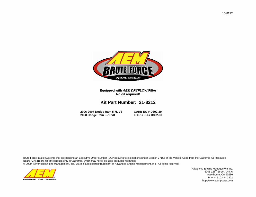
9456 (2)
9060

10-8212
21-8212 Page 3 of 10 01.23.2009 Rev 2
Bill of Materials
Part Number Description Qty
2-82123 Inlet Pipe 1
21-2049D Air Filter, 3.50"X9” Dryflow 1
9456 #56 Hose Clamp 2
9460 #60 Hose Clamp 1
5-351 Coupler, 3.50"x2.0" 1
20-8212 Heat Shield 1
8-119 Sponge Rubber Gasket 22
8-111 Rubber Edge Trim 34
784640 Rubber Grommet, 1" ID 1
1228560 Rubber Mount, M8 1
559960 Fender Washer, M8 2
444.460.08 M8 Nut 2
2-9004 Throttle Body Spacer 1
1-2089 Bolt, M6x1.0x90mm 4
1-3018 Flat Washer, M6 4
784634 Grommet, 1/2" 1
1-3037 O-Ring 1
10-8212 Instructions 1
10-922S AEM Decal 2
8-139 Connector 90 Deg 3/4" 1
10-8212
21-8212 Page 4 of 10 01.23.2009 Rev 2
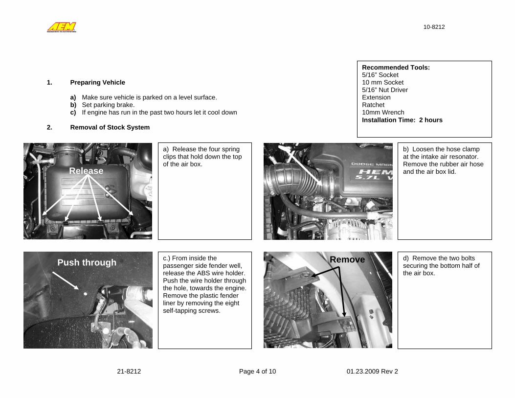
1. Preparing Vehicle
a) Make sure vehicle is parked on a level surface. b) Set parking brake. c) If engine has run in the past two hours let it cool down
2. Removal of Stock System
a) Release the four spring clips that hold down the top of the air box.
b) Loosen the hose clamp at the intake air resonator. Remove the rubber air hose and the air box lid.
c.) From inside the passenger side fender well, release the ABS wire holder. Push the wire holder through the hole, towards the engine. Remove the plastic fender liner by removing the eight self-tapping screws.
d) Remove the two bolts securing the bottom half of the air box.
Recommended Tools: 5/16” Socket 10 mm Socket 5/16” Nut Driver Extension Ratchet 10mm Wrench Installation Time: 2 hours
Release
Push through Remove
10-8212
21-8212 Page 5 of 10 01.23.2009 Rev 2
Remove
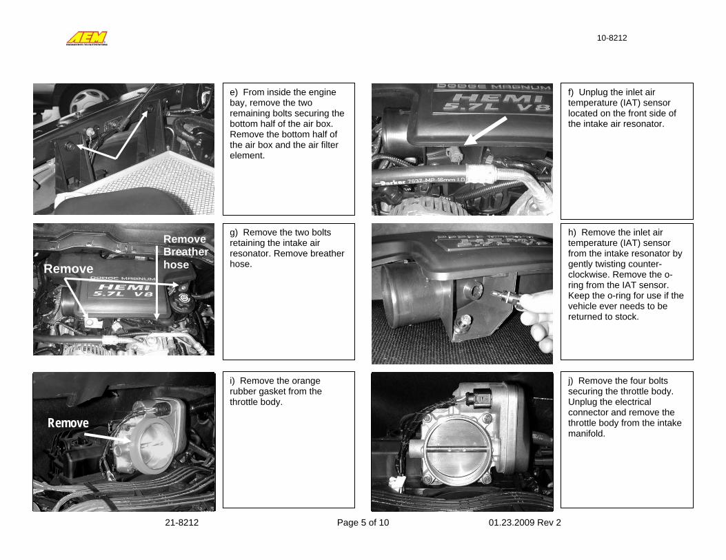
e) From inside the engine bay, remove the two remaining bolts securing the bottom half of the air box. Remove the bottom half of the air box and the air filter element.
f) Unplug the inlet air temperature (IAT) sensor located on the front side of the intake air resonator.
g) Remove the two bolts retaining the intake air resonator. Remove breather hose.
h) Remove the inlet air temperature (IAT) sensor from the intake resonator by gently twisting counter-clockwise. Remove the o-ring from the IAT sensor. Keep the o-ring for use if the vehicle ever needs to be returned to stock.
i) Remove the orange rubber gasket from the throttle body.
j) Remove the four bolts securing the throttle body. Unplug the electrical connector and remove the throttle body from the intake manifold.
Remove
Remove Breather hose

10-8212
21-8212 Page 6 of 10 01.23.2009 Rev 2
3. Installation of Brute Force Intake
a) When installing the intake system, DO NOT completely tighten the hose clamps or mounting tab hardware until instructed to do so.
b) Install the supplied rubber mount into the heat shield as shown, place a M8 washer on the stud and a M8 nut to secure.
d) Install the throttle body spacer, aligning the pins on the intake manifold with the holes in the back of the throttle body spacer. The o-ring groove on the spacer should be facing forward.
c) Install the supplied o-ring into the groove in the front of the throttle body spacer. Make sure the o-ring is properly seated in the groove around the entire circumference. Use a small amount of grease to trap O-Ring in place.
e) Install the throttle body using the supplied M6 bolts and washers. Align the dowel pins on the throttle body spacer with the holes in the throttle body. Before installing the throttle body spacer, make sure the O-Ring is seated. Reconnect the electrical connector.
f) On trucks equipped with the optional under hood light on the passenger side, cut the corners on the small section of the top notch in the heat shield using a hacksaw or other suitable tool. Bend the tab back and forth until it breaks free. Clean up any sharp edges with a file. For installation on all other trucks, proceed to next step.
g) Install the rubber edge trim (PN: 8-111) on the edges indicated with the white arrows. Install the sponge rubber gasket (PN: 8-119) along the top of the heat shield indicated with black arrows. Cut
Here
10-8212
21-8212 Page 7 of 10 01.23.2009 Rev 2
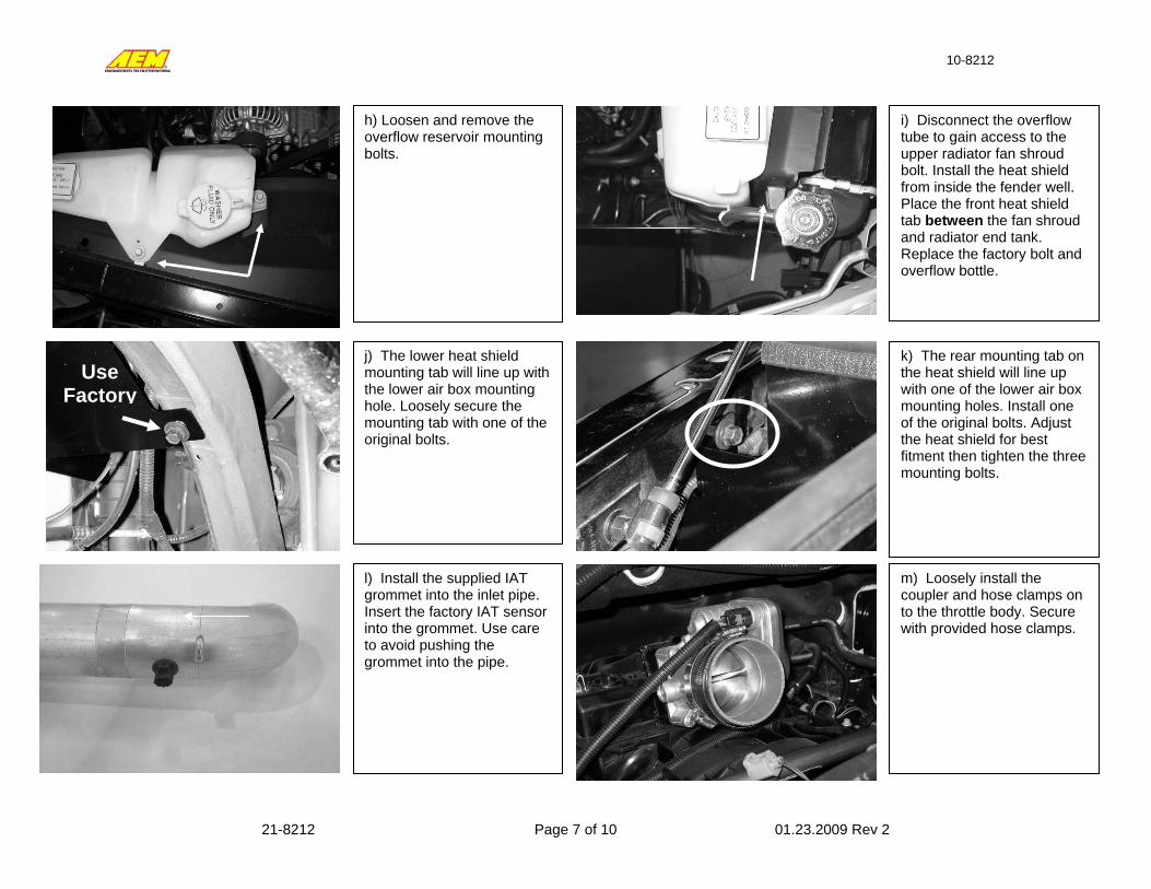
h) Loosen and remove the overflow reservoir mounting bolts.
i) Disconnect the overflow tube to gain access to the upper radiator fan shroud bolt. Install the heat shield from inside the fender well. Place the front heat shield tab between the fan shroud and radiator end tank. Replace the factory bolt and overflow bottle.
j) The lower heat shield mounting tab will line up with the lower air box mounting hole. Loosely secure the mounting tab with one of the original bolts.
k) The rear mounting tab on the heat shield will line up with one of the lower air box mounting holes. Install one of the original bolts. Adjust the heat shield for best fitment then tighten the three mounting bolts.
l) Install the supplied IAT grommet into the inlet pipe. Insert the factory IAT sensor into the grommet. Use care to avoid pushing the grommet into the pipe.
Use Factory
m) Loosely install the coupler and hose clamps on to the throttle body. Secure with provided hose clamps.

10-8212
21-8212 Page 8 of 10 01.23.2009 Rev 2
n) Insert the 1” grommet into the pipe. Insert the 90 degree plastic connector into the grommet. Be careful not to push the grommet through the pipe.
o) Insert the pipe as shown. Line up the support bracket to the rubber mount and secure. Reconnect the IAT sensor wire harness. See diagram on the next page.
p) Reconnect the PCV breather hose to the 90 degree fitting from step 3n. Check for clearance against the inlet pipe.
q) To increase the clearance of the breather hose and the inlet pipe, rotate the breather line at the PCV outlet counterclockwise. Release the spring clamp to rotate.
Rubber Mount Inlet Pipe Bracket
Flat Washer
Locknut
10-8212
21-8212 Page 9 of 10 01.23.2009 Rev 2
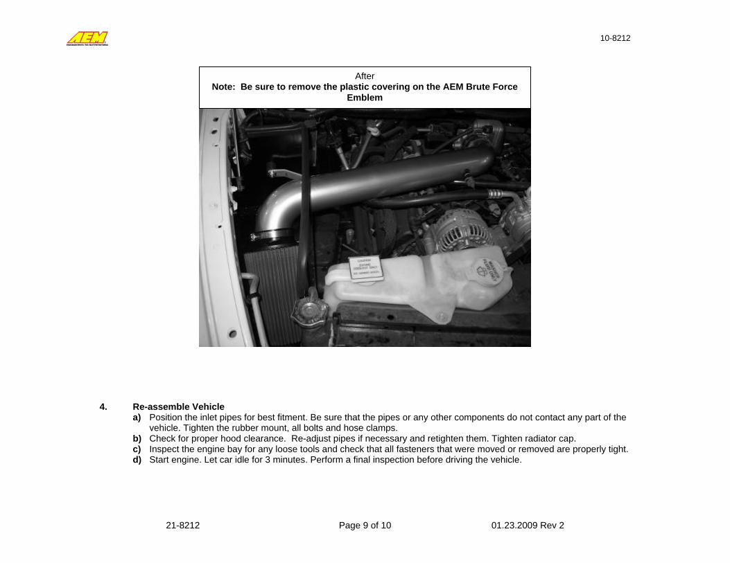
4. Re-assemble Vehicle
a) Position the inlet pipes for best fitment. Be sure that the pipes or any other components do not contact any part of the vehicle. Tighten the rubber mount, all bolts and hose clamps.
b) Check for proper hood clearance. Re-adjust pipes if necessary and retighten them. Tighten radiator cap. c) Inspect the engine bay for any loose tools and check that all fasteners that were moved or removed are properly tight. d) Start engine. Let car idle for 3 minutes. Perform a final inspection before driving the vehicle.
After Note: Be sure to remove the plastic covering on the AEM Brute Force
Emblem
10-8212
21-8212 Page 10 of 10 01.23.2009 Rev 2
For technical inquiries e-mail us at
call us at 310.484.2322 Option #3
5. Service and Maintenance a) It is recommended that you service your AEM Dryflow filter every 20,000 miles for optimum performance. Use AEM
Dryflow cleaning kit part # 21-110. b) Use aluminum polish to clean your polished AEM Brute Force intake pipe.
c) Use window cleaner to clean your powder coated AEM Brute Force intake pipe. (NOTE: DO NOT USE Aluminum polish on a powder coated AEM BRUTE FORCE intake pipe)
AEM Lifetime Warranty Advanced Engine Management Inc. warrants to the consumer that AEM intake systems will be free from defects in material and workmanship for the lifetime of the product. Products that fail will be repaired or replaced at AEM’s option, when determined by AEM that the product failed due to defects in material or workmanship. This warranty is limited to the repair or replacement of the AEM part. In no event shall this warranty exceed the original purchase price of the AEM part nor shall AEM be responsible for special, incidental, or consequential damages or cost incurred due to the failure of this product. Warranty claims to AEM must be transportation prepaid and accompanied with dated proof of purchase. This warranty applies only to the original purchaser of product and is non-transferable. Improper use or installation, accident, abuse, unauthorized repairs, alterations, flying debris, or other negligence voids this warranty. AEM disclaims any liability for consequential damages due to breach of any written or implied warranty on all products. Warranty returns will only be accepted by AEM when accompanied by a valid Return Merchandise Authorization (RMA) number. Product must be received by AEM within 30 days of the date the RMA is issued. Please note that before AEM can issue an RMA for any intake product, it is first necessary for the installer or end user to contact customer service at (310) 484-2322. Most issues can be resolved over the phone. Under no circumstances should a system be returned or an RMA requested before the above process has transpired. AEM will not be responsible for intake systems and products that are installed incorrectly, installed in a non-approved application, misused, tampered, or modified. AEM will not warrant its powder-coating if the finish has been cleaned with anything other than a mild soap and water solution.