Embed Size (px)
Citation preview
28209 Avenue Stanford, Valencia, California 91355
661 257-4411 | fax 661 294-4179 | www.answerproducts.com
2004 SERVICE MANUALSix Six Sport
04 SIX SERVICE MANUAL Page 2 REV NC
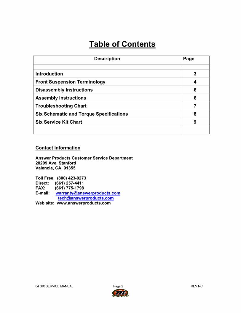
Table of Contents
Description Page
Introduction 3
Front Suspension Terminology 4
Disassembly Instructions 6
Assembly Instructions 6
Troubleshooting Chart 7
Six Schematic and Torque Specifications 8
Six Service Kit Chart 9
Contact Information
Answer Products Customer Service Department28209 Ave. StanfordValencia, CA 91355
Toll Free: (800) 423-0273Direct: (661) 257-4411FAX: (661) 775-1798E-mail: [email protected] [email protected] site: www.answerproducts.com
04 SIX SERVICE MANUAL Page 3 REV NC
INTRODUCTION
This manual is intended to guide the user through basic service of Manitou Six front forks.Service is supported by the identification of common parts and assemblies that have beenassembled into Service Kits. The purpose of this manual will be to describe conditions that maydrive the need for service and to provide installation instructions for the kits.
Due to the time-consuming nature suspension fork service, at this time our primary focus is tooffer service kits that minimize the amount of downtime and labor involved.
Important information is highlighted in this manual by the following notations:
WARNINGFailure to follow WARNING instructions could result in severe injury or death to theperson inspecting or repairing the suspension fork or the user.
CAUTIONA CAUTION a caution indicates special precautions that must be taken to avoid damage tothe product.
NOTEA NOTE provides key information to make procedures easier or clearer
GENERAL WARNING: Suspension forks by design can contain preloaded springs, gasesand fluids under extreme pressure and warnings contained in this manual must beobserved to reduce the possibility of injury or possible death. Following theseinstructions can help you reduce the risk of being injured. Any questions in regards to theinformation in this manual should be directed to Answer Products Customer Service at(661) 257-4411.
WARNING: Suspension forks uses preloaded spring(s) to provide compression springresistance. This system must be relieved of preload prior to servicing. Failure to relieveair pressure could result in injury or possible death.
CAUTION: Suspension forks use precision machined aluminum and other soft alloy components.Using correct tools for assembly is essential to prevent damage.
04 SIX SERVICE MANUAL Page 4 REV NC
GLOSSARY OF TERMS
Arch – A support that connects the two outer lower legs of the casting so as to keep them movingin unison.
Boss – The word used to describe an outer casting that has brake posts for V-brakes orcantilever brakes.
Bottom Out Bumper – A rubber or elastomer device that absorbs the shock that occurs when asuspension is compression to its limit.
Bushings – A cylindrical sleeve between a fork stanchion tube (inner leg) and a fork outercasting (slider), which facilitates the sliding movement between these two parts.
Coil Spring – A coiled piece of metal that acts as a spring to help suspend a fork.
Compression – The phase of the suspension operation in which the wheel travels up, or travelscloser to the frame. The suspension forks reaction to a bump in the trail.
Convertible Travel – A system used to alter the travel of a suspension fork. It requires moving atravel clip on the compression rod to a different position. This operation is accomplished bydisassembling the fork and physically moving the travel clip on the compression rod.
Crown Steerer Assembly – the stanchion legs (inner legs), the fork crown, and the steer tubepressed together as one assembly. This assembly is then finished by adding all of the forkinternals and then outer casting (slider).
Drop Out – The end of an outer casting (slider) where the wheel attaches.
Dust Boot – Usually a piece of rubber in the shape of a cylinder with baffles to allow it tocompress as the fork compresses through its travel. Its function is to help keep dirt and waterfrom getting into the inner legs of the fork.
Fork Crown – The component that joins the stanchion tubes (inner legs) to the steer tube of thefork.
MCU – (Micro-Cellular Urethane) Special urethane that is filled with tiny air cells that act likesprings when the elastomer is compressed.
No Boss - The word used to describe an outer casting that has no brake posts for V-brakes orcantilever brakes. This casting is to be used for disk brakes only.
O-Ring – A soft, flexible neoprene or Buna rubber ring with a round cross-section, which is usedfor sealing and retention.
Outer Casting – (see Slider)
Preload – A condition of compressing a spring or elastomer before the operating loads are put onthe suspension, so that it provides a stiffer spring rate.
Rebound – The phase of the suspension operation in which the wheel returns to its originalposition on the ground after compression.
04 SIX SERVICE MANUAL Page 5 REV NC
Reverse Arch Technology – Also known as RA. It is a system that is designed to move the archof a fork to the backside of a fork, rather than the conventional front position. It was designed toprovide greater rotational torque strength to an outer casting (slider), without adding additionalweight to the fork.
SAG – The amount a suspension fork compresses at rest with a normal load (rider’s weight).
Seal – A part, usually neoprene rubber or Buna, that keeps contaminants out and/or workingfluids in.
Spring Rate – The rate at which the resistance of a spring increases as it is compressed.
Slider/Outer Casting – The tube (outer casting leg) of the suspension fork that remains fixed tothe wheel. It slides up and down on the stanchion leg (inner leg).
Stanchion Legs – The suspension tube (inner leg) fixed to the fork crown. It remains stationaryduring the operation of the suspension.
Steer Tube – The long cylindrical tube that extends from the top of the fork crown. Its function isto be inserted into the bicycle head tube and attach the suspension to the bicycle frame.
Top Out Bumper – A rubber, coil spring, or elastomer device that absorbs the shock that occurswhen the load is taken off a suspension so that it is allowed to rebound to its limits
Travel – The amount that a wheel moves between the most compressed and the most extendedstates of the suspension
Wiper Seal – A rubber material that is used as a seal to keep dirt and water out of the outercasting legs. It is not designed to keep air pressure or extreme oil pressure in. Manitou has thenew Evil Genius wiper seals.
04 SIX SERVICE MANUAL Page 6 REV NC
2004 Six Forks Disassembly and Rebuild Instructions
Disassembly Instructions
WARNING This fork uses a preloaded coil spring provide spring resistance. Thespring must be relieved of its preload prior to servicing. Failure to do so could resultin injury or possible death.
1. From the left leg dropout (Left when sitting on the bike), use a 4mm hex wrench toremove the compression rod screw.
2. From the right leg dropout, use an 6mm hex wrench to turn the compression rodclockwise until it can be pushed into the casting. If you cannot unscrew thecompression rod see step 7.
3. Remove crown/steer/inner leg assembly from the outer leg casting.4. Turn spring preload adjuster knob counter clockwise until it stops. Remove 2mm hex
screw on spring preload adjuster knob and remove knob on the top left side of the fork.5. Remove preload adjuster using 18mm socket.6. Compress fork and remove the spring preload, MCU, and spring assy.7. Remove top leg cap on right hand side using 27mm socket.8. If you could not remove the right side compression rod externally, reach down inside the
inner leg with a 6mm hex, the top of the compression rod has a recessed 6mm hex that ahex wrench will fit into. The comp rod can be unscrewed counterclockwise at this point.Remove crown/steer/inner leg assembly from the outer leg casting.
9. Remove rubber bumper and clip on compression rods.10. Turn crown/steer upside down to allow the comp rods to fall out of the inner legs.
Setting Travel
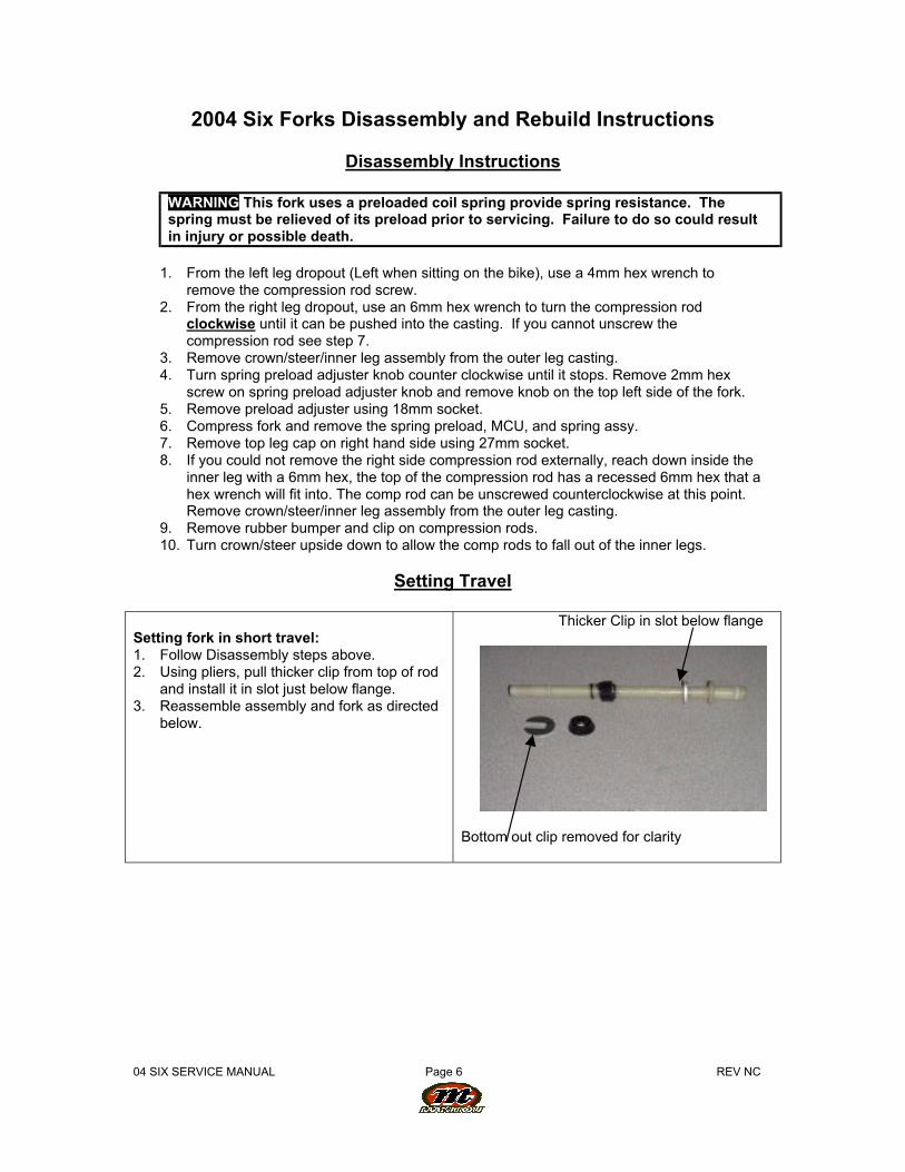
Setting fork in short travel:1. Follow Disassembly steps above.2. Using pliers, pull thicker clip from top of rod
and install it in slot just below flange.3. Reassemble assembly and fork as directed
below.
Thicker Clip in slot below flange
Bottom out clip removed for clarity
04 SIX SERVICE MANUAL Page 7 REV NC
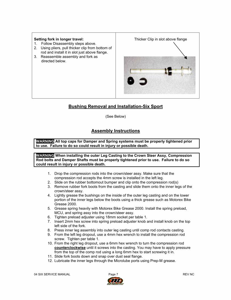
Setting fork in longer travel:1. Follow Disassembly steps above.2. Using pliers, pull thicker clip from bottom of
rod and install it in slot just above flange.3. Reassemble assembly and fork as directed below.
Thicker Clip in slot above flange
Bushing Removal and Installation-Six Sport
(See Below)
Assembly Instructions
WARNING All top caps for Damper and Spring systems must be properly tightened priorto use. Failure to do so could result in injury or possible death.
WARNING When installing the outer Leg Casting to the Crown Steer Assy, CompressionRod bolts and Damper Shafts must be properly tightened prior to use. Failure to do socould result in injury or possible death.
1. Drop the compression rods into the crown/steer assy. Make sure that thecompression rod accepts the 4mm screw is installed in the left leg.
2. Slide on the rubber bottomout bumper and clip onto the compression rod(s)3. Remove rubber fork boots from the casting and slide them onto the inner legs of the
crown/steer assy.4. Lightly grease the bushings on the inside of the outer leg casting and on the lower
portion of the inner legs below the boots using a thick grease such as Motorex BikeGrease 2000.
5. Grease spring heavily with Motorex Bike Grease 2000. Install the spring preload,MCU, and spring assy into the crown/steer assy.
6. Tighten preload adjuster using 18mm socket per table 1.7. Insert 2mm hex screw into spring preload adjuster knob and install knob on the top
left side of the fork.8. Press inner leg assembly into outer leg casting until comp rod contacts casting.9. From the left leg dropout, use a 4mm hex wrench to install the compression rod
screw. Tighten per table 1.10. From the right leg dropout, use a 6mm hex wrench to turn the compression rod
counterclockwise until it screws into the casting. You may have to apply pressurefrom the top of the comp rod using a long 6mm hex to start screwing it in.
11. Slide fork boots down and snap over dust seal flange.12. Lubricate the inner legs through the Microlube ports using Prep-M grease.

04 SIX SERVICE MANUAL Page 8 REV NC
Bushing Removal & Installation
Bushing Removal
(Note: use appropriate removal ring that corresponds to the leg diameter of the fork beingrepaired)
Leg Diameter Answer Kit #25.4mm (1”) 85-519128.6mm (11/8”) 85-518930mm 85-519432mm 85-5192
Bushing Removal Tool ComponentsA. Slide HammerB. Threaded HandleC. SlideD. Threaded ShaftE. Removal Ring
Bushing Removal Tool Assembly
04 SIX SERVICE MANUAL Page 9 REV NC
Bushing Removal (CONT.)
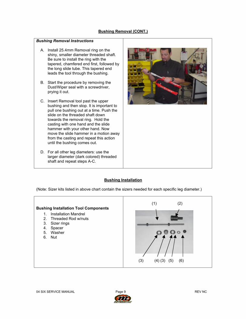
Bushing Removal Instructions
A. Install 25.4mm Removal ring on theshiny, smaller diameter threaded shaft.Be sure to install the ring with thetapered, chamfered end first, followed bythe long slide tube. This tapered endleads the tool through the bushing.
B. Start the procedure by removing theDust/Wiper seal with a screwdriver,prying it out.
C. Insert Removal tool past the upperbushing and then stop. It is important topull one bushing out at a time. Push theslide on the threaded shaft downtowards the removal ring. Hold thecasting with one hand and the slidehammer with your other hand. Nowmove the slide hammer in a motion awayfrom the casting and repeat this actionuntil the bushing comes out.
D. For all other leg diameters: use thelarger diameter (dark colored) threadedshaft and repeat steps A-C.
Bushing Installation
(Note: Sizer kits listed in above chart contain the sizers needed for each specific leg diameter.)
Bushing Installation Tool Components
1. Installation Mandrel2. Threaded Rod w/nuts3. Sizer rings4. Spacer5. Washer6. Nut
(1) (2)
(3) (4) (3) (5) (6)
04 SIX SERVICE MANUAL Page 10 REVNC
Bushing Installation (CONT.)
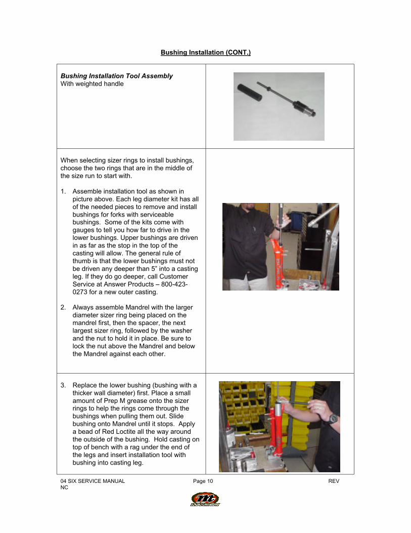
Bushing Installation Tool AssemblyWith weighted handle
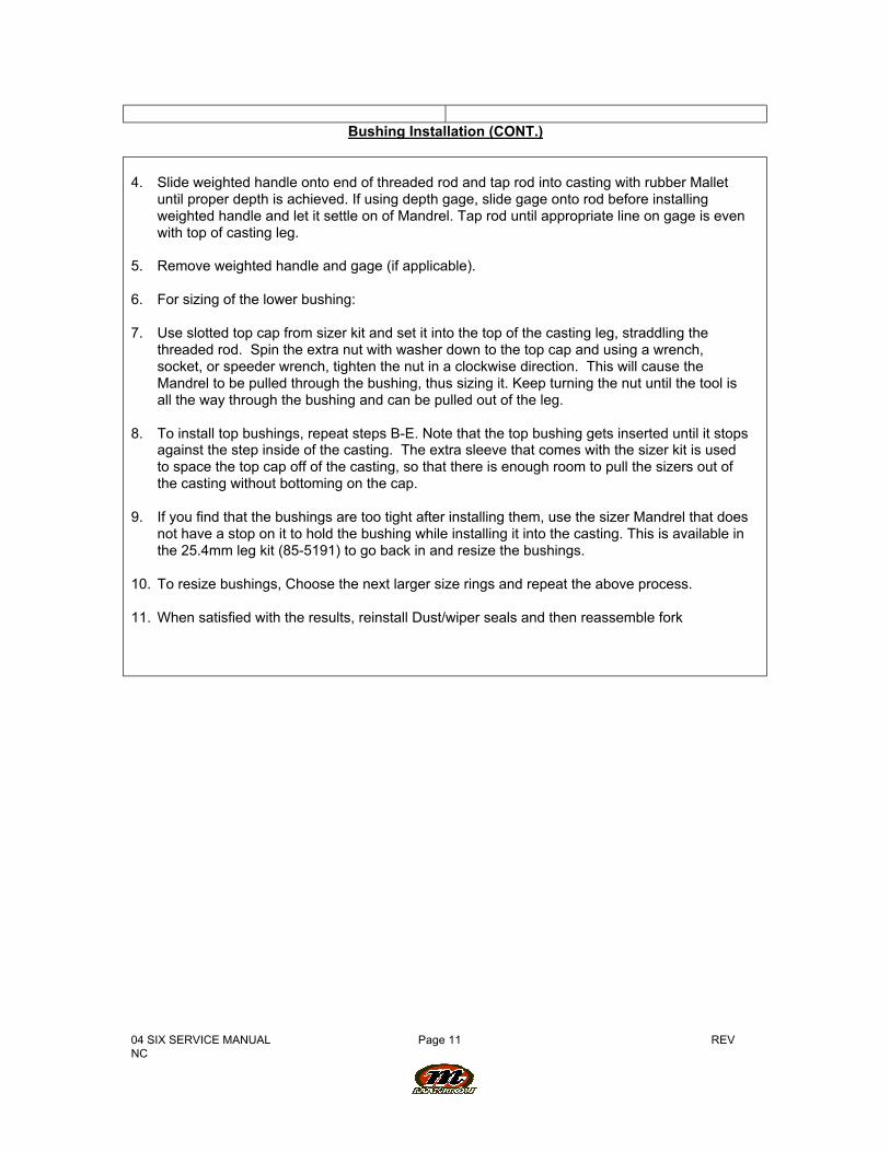
When selecting sizer rings to install bushings,choose the two rings that are in the middle ofthe size run to start with.
1. Assemble installation tool as shown inpicture above. Each leg diameter kit has allof the needed pieces to remove and installbushings for forks with serviceablebushings. Some of the kits come withgauges to tell you how far to drive in thelower bushings. Upper bushings are drivenin as far as the stop in the top of thecasting will allow. The general rule ofthumb is that the lower bushings must notbe driven any deeper than 5” into a castingleg. If they do go deeper, call CustomerService at Answer Products – 800-423-0273 for a new outer casting.
2. Always assemble Mandrel with the largerdiameter sizer ring being placed on themandrel first, then the spacer, the nextlargest sizer ring, followed by the washerand the nut to hold it in place. Be sure tolock the nut above the Mandrel and belowthe Mandrel against each other.
3. Replace the lower bushing (bushing with athicker wall diameter) first. Place a smallamount of Prep M grease onto the sizerrings to help the rings come through thebushings when pulling them out. Slidebushing onto Mandrel until it stops. Applya bead of Red Loctite all the way aroundthe outside of the bushing. Hold casting ontop of bench with a rag under the end ofthe legs and insert installation tool withbushing into casting leg.
04 SIX SERVICE MANUAL Page 11 REVNC
Bushing Installation (CONT.)
4. Slide weighted handle onto end of threaded rod and tap rod into casting with rubber Malletuntil proper depth is achieved. If using depth gage, slide gage onto rod before installingweighted handle and let it settle on of Mandrel. Tap rod until appropriate line on gage is evenwith top of casting leg.
5. Remove weighted handle and gage (if applicable).
6. For sizing of the lower bushing:
7. Use slotted top cap from sizer kit and set it into the top of the casting leg, straddling thethreaded rod. Spin the extra nut with washer down to the top cap and using a wrench,socket, or speeder wrench, tighten the nut in a clockwise direction. This will cause theMandrel to be pulled through the bushing, thus sizing it. Keep turning the nut until the tool isall the way through the bushing and can be pulled out of the leg.
8. To install top bushings, repeat steps B-E. Note that the top bushing gets inserted until it stopsagainst the step inside of the casting. The extra sleeve that comes with the sizer kit is usedto space the top cap off of the casting, so that there is enough room to pull the sizers out ofthe casting without bottoming on the cap.
9. If you find that the bushings are too tight after installing them, use the sizer Mandrel that doesnot have a stop on it to hold the bushing while installing it into the casting. This is available inthe 25.4mm leg kit (85-5191) to go back in and resize the bushings.
10. To resize bushings, Choose the next larger size rings and repeat the above process.
11. When satisfied with the results, reinstall Dust/wiper seals and then reassemble fork
04 SIX SERVICE MANUAL Page 12 REVNC
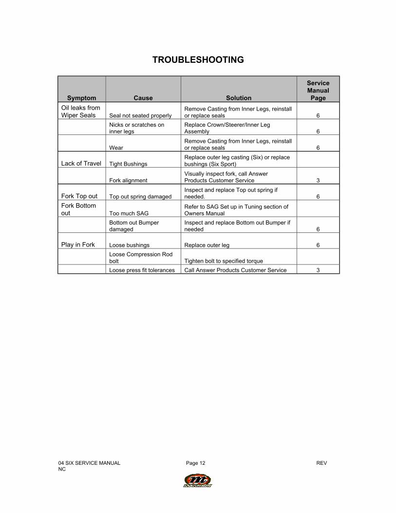
TROUBLESHOOTING
Symptom Cause Solution
ServiceManualPage
Oil leaks fromWiper Seals Seal not seated properly
Remove Casting from Inner Legs, reinstallor replace seals 6
Nicks or scratches oninner legs
Replace Crown/Steerer/Inner LegAssembly 6
WearRemove Casting from Inner Legs, reinstallor replace seals 6
Lack of Travel Tight BushingsReplace outer leg casting (Six) or replacebushings (Six Sport)
Fork alignmentVisually inspect fork, call AnswerProducts Customer Service 3
Fork Top out Top out spring damagedInspect and replace Top out spring ifneeded. 6
Fork Bottomout Too much SAG
Refer to SAG Set up in Tuning section ofOwners Manual
Bottom out Bumperdamaged
Inspect and replace Bottom out Bumper ifneeded 6
Play in Fork Loose bushings Replace outer leg 6
Loose Compression Rodbolt Tighten bolt to specified torque
Loose press fit tolerances Call Answer Products Customer Service 3
04 SIX SERVICE MANUAL Page 13 REVNC
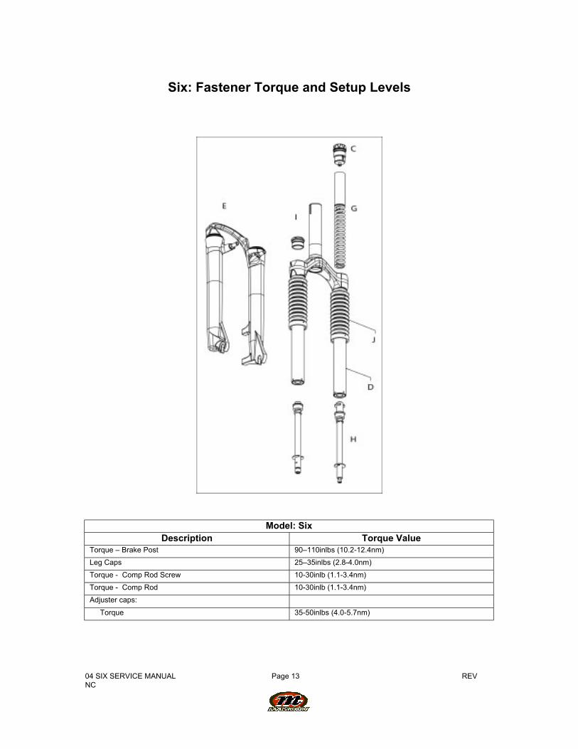
Six: Fastener Torque and Setup Levels
Model: SixDescription Torque Value
Torque – Brake Post 90–110inlbs (10.2-12.4nm)
Leg Caps 25–35inlbs (2.8-4.0nm)
Torque - Comp Rod Screw 10-30inlb (1.1-3.4nm)
Torque - Comp Rod 10-30inlb (1.1-3.4nm)
Adjuster caps:
Torque 35-50inlbs (4.0-5.7nm)
04 SIX SERVICE MANUAL Page 14 REVNC
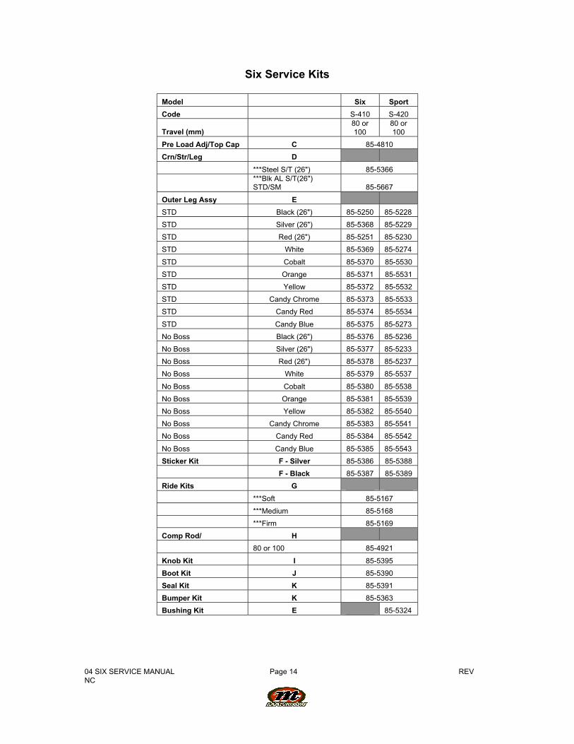
Six Service Kits
Model Six Sport
Code S-410 S-420
Travel (mm) 80 or100
80 or100
Pre Load Adj/Top Cap C 85-4810
Crn/Str/Leg D
***Steel S/T (26") 85-5366
***Blk AL S/T(26")STD/SM 85-5667
Outer Leg Assy E
STD Black (26") 85-5250 85-5228
STD Silver (26") 85-5368 85-5229
STD Red (26") 85-5251 85-5230
STD White 85-5369 85-5274
STD Cobalt 85-5370 85-5530
STD Orange 85-5371 85-5531
STD Yellow 85-5372 85-5532
STD Candy Chrome 85-5373 85-5533
STD Candy Red 85-5374 85-5534
STD Candy Blue 85-5375 85-5273
No Boss Black (26") 85-5376 85-5236
No Boss Silver (26") 85-5377 85-5233
No Boss Red (26") 85-5378 85-5237
No Boss White 85-5379 85-5537
No Boss Cobalt 85-5380 85-5538
No Boss Orange 85-5381 85-5539
No Boss Yellow 85-5382 85-5540
No Boss Candy Chrome 85-5383 85-5541
No Boss Candy Red 85-5384 85-5542
No Boss Candy Blue 85-5385 85-5543
Sticker Kit F - Silver 85-5386 85-5388
F - Black 85-5387 85-5389
Ride Kits G
***Soft 85-5167
***Medium 85-5168
***Firm 85-5169
Comp Rod/ H
80 or 100 85-4921
Knob Kit I 85-5395
Boot Kit J 85-5390
Seal Kit K 85-5391
Bumper Kit K 85-5363
Bushing Kit E 85-5324
04 SIX SERVICE MANUAL Page 15 REVNC
Six Service Kits (Cont.)