Embed Size (px)
Citation preview
L591002
2004Fresh Water
Cooling InstallationInstructions -
V-DriveKit RK147050A

L591002
This Page Was
Intentially
Left Blank
1L591002
RK147050A
1 - FWC Kit Installation Instructions - V-Drive ................................................................................. Table of Contents ...................................... ........................................................................................... 1Installation Notes and Recommendations ........................................................................................... 2Figure 1-1, Parts Deleted, Raw Water System, V-Drive ................................................................... 3-6Figure 1-2, Parts Added, Raw Water System, V-Drive ................................................................. 7-10FWC Kit Installation, V-Drive Systems ....................................................................................... 11-212 - Fresh Water Cooling Water Flow Diagram ................................................................................. 22
TABLE OF CONTENTS
2L591002
RK147050A
FWC KIT INSTALLATION INSTRUCTIONS - RK147050AINSTALLATION NOTES AND RECOMMENDATIONS
PCM Technical Support, Warranty and Dealer Assistance:
• Phone: (803) 345-0050 • Fax: (800) 321-3797 • E-mail: [email protected] • E-mail: [email protected]
REFERENCES:
L510013 Marine Illustrated Parts Manual Model MP5.0/5.7L MY 2002 - 2004
L510010-04 Owner’s Operation and Maintenance Manual
NOTE: Use pipe sealant with Tefl on on all fi ttings being installed during these procedures. Loctite™ 565, PST Pipe Sealant, Part No. 56541 or equivalent is recommended.
V-DRIVE INSTALLATION
Installation of the fresh water cooling system on V-drive applications will require relocation of both the low pressure fuel pump and the FCC, and servicing of the high pressure and return fuel lines. To complete the installation procedure you will require a fuel gauge equipped with a pressure release valve, an approved container to vent gasoline into, and the proper tools for releasing the fuel lines from the fuel rails. Provisions should be made to recover any fuel spilled. Observe all safety warnings and cautions when working on the fuel system.
WARNING
Extreme caution must be exercised when servicing the fuel system and/or replacing fuel fi lter. Gasoline is extremely fl ammable and highly explosive under certain conditions. Be sure the ignition key is off and do not smoke, or allow open fl ame in the area while servicing. Wipe up any spilled fuel immediately.
WARNING
Make sure that there are no fuel leaks before closing the engine hatch.
WARNING
Visually inspect unit for fuel leaks before operating the engine. If fuel leaks are present, DO NOT operate the engine, repair immediately.
WARNING
Do not remove cooling system fi ller cap when the engine is hot. Allow the engine to cool and then remove the pressure cap slowly, allowing the pressure to vent. Hot coolant, under pressure, may discharge violently and cause severe burns.
WARNING
Fire and Explosion Hazard - Gasoline is extremely fl ammable and highly explosive, and, if ignited, can cause serious bodily injury or death. Careful inspection of the entire fuel system including, but not limited to, fuel tanks, fuel lines, fuel fi lters and all fi ttings is mandatory, especially after periods of storage. Replace any component that shows signs of leakage, corrosion, deterioration, swelling, hardening or softening.
3L591002
RK147050A
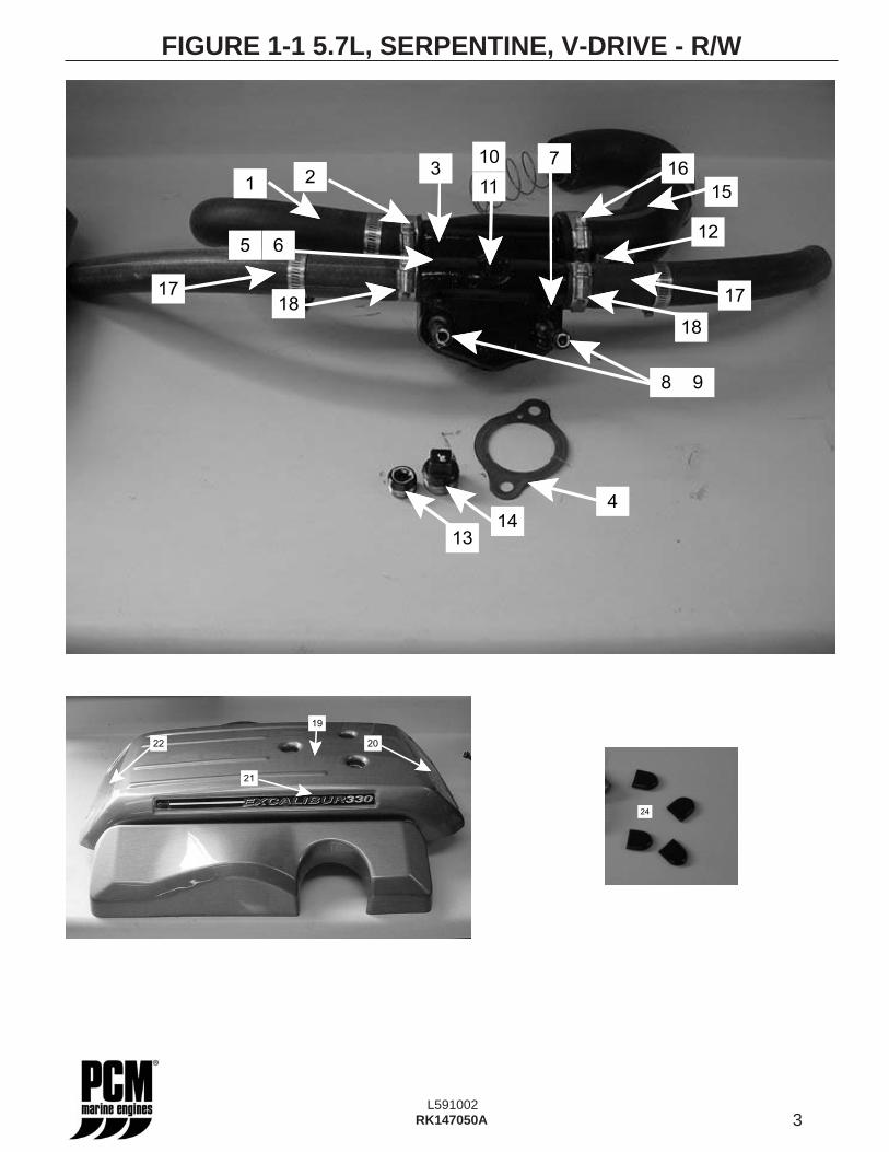
FIGURE 1-1 5.7L, SERPENTINE, V-DRIVE - R/W
4
1413
98
10
2116
15
37
12
18
6
17
11
5
17
18
20
21
19
22
24
4L591002
RK147050A
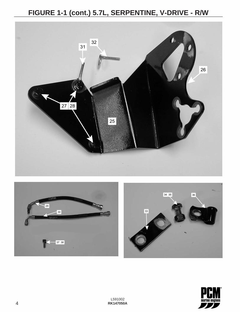
FIGURE 1-1 (cont.) 5.7L, SERPENTINE, V-DRIVE - R/W
2827
31
32
25
26
30
37
29
38
33
3634 35
5L591002
RK147050A
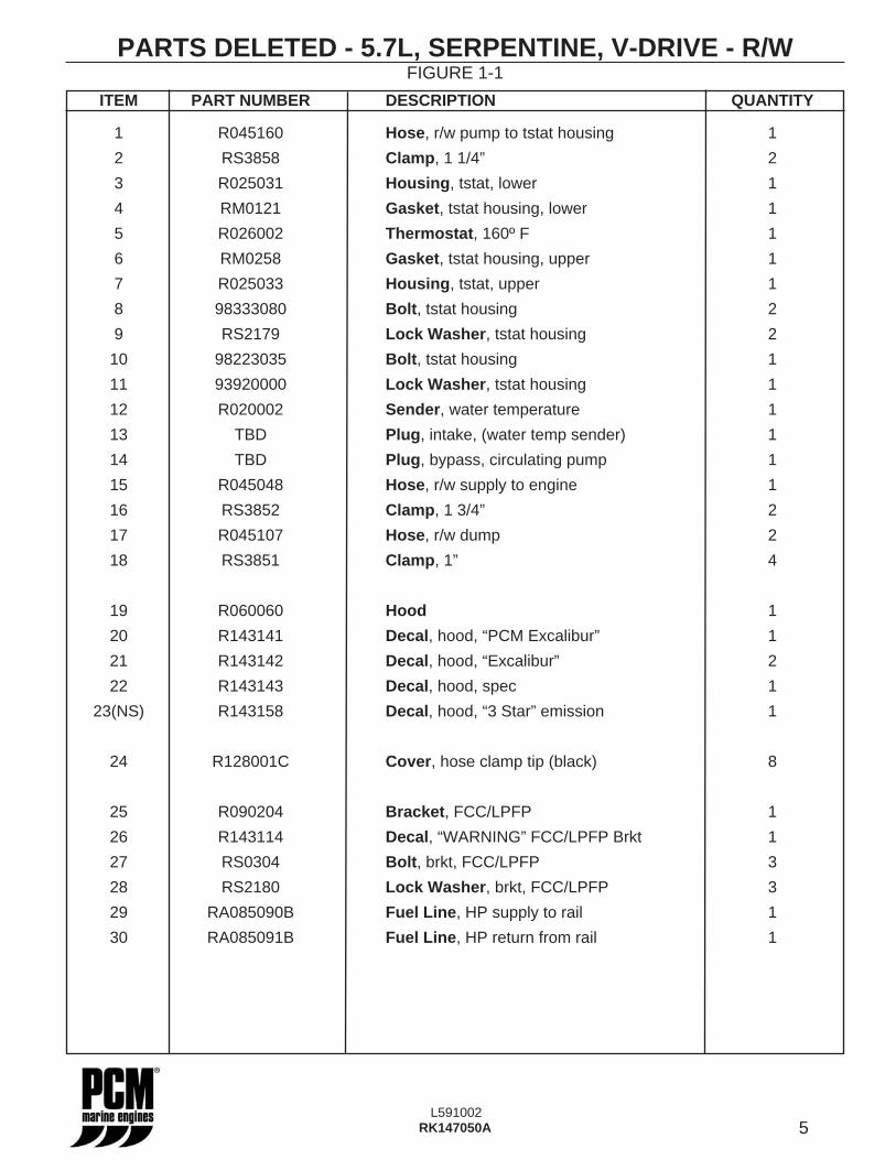
PARTS DELETED - 5.7L, SERPENTINE, V-DRIVE - R/W
ITEM PART NUMBER DESCRIPTION QUANTITY
1 R045160 Hose, r/w pump to tstat housing 1
2 RS3858 Clamp, 1 1/4” 2
3 R025031 Housing, tstat, lower 1
4 RM0121 Gasket, tstat housing, lower 1
5 R026002 Thermostat, 160º F 1
6 RM0258 Gasket, tstat housing, upper 1
7 R025033 Housing, tstat, upper 1
8 98333080 Bolt, tstat housing 2
9 RS2179 Lock Washer, tstat housing 2
10 98223035 Bolt, tstat housing 1
11 93920000 Lock Washer, tstat housing 1
12 R020002 Sender, water temperature 1
13 TBD Plug, intake, (water temp sender) 1
14 TBD Plug, bypass, circulating pump 1
15 R045048 Hose, r/w supply to engine 1
16 RS3852 Clamp, 1 3/4” 2
17 R045107 Hose, r/w dump 2
18 RS3851 Clamp, 1” 4
19 R060060 Hood 1
20 R143141 Decal, hood, “PCM Excalibur” 1
21 R143142 Decal, hood, “Excalibur” 2
22 R143143 Decal, hood, spec 1
23(NS) R143158 Decal, hood, “3 Star” emission 1
24 R128001C Cover, hose clamp tip (black) 8
25 R090204 Bracket, FCC/LPFP 1
26 R143114 Decal, “WARNING” FCC/LPFP Brkt 1
27 RS0304 Bolt, brkt, FCC/LPFP 3
28 RS2180 Lock Washer, brkt, FCC/LPFP 3
29 RA085090B Fuel Line, HP supply to rail 1
30 RA085091B Fuel Line, HP return from rail 1
FIGURE 1-1
6L591002
RK147050A
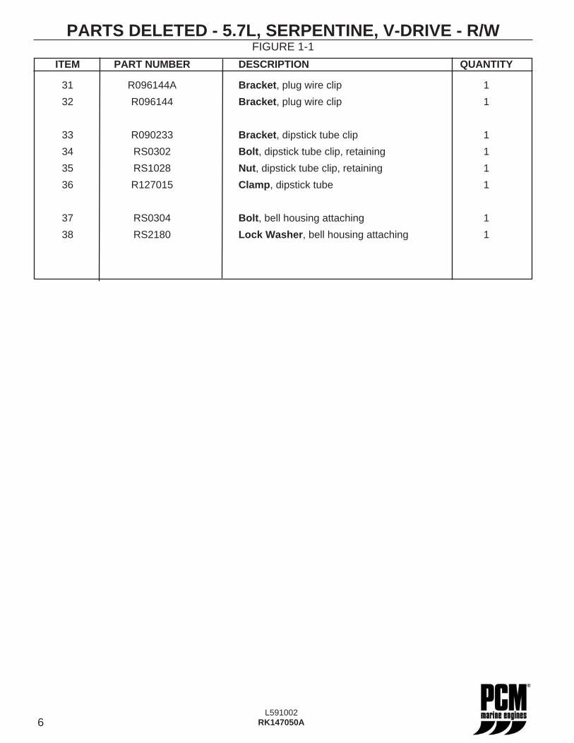
PARTS DELETED - 5.7L, SERPENTINE, V-DRIVE - R/W
ITEM PART NUMBER DESCRIPTION QUANTITY
31 R096144A Bracket, plug wire clip 1
32 R096144 Bracket, plug wire clip 1
33 R090233 Bracket, dipstick tube clip 1
34 RS0302 Bolt, dipstick tube clip, retaining 1
35 RS1028 Nut, dipstick tube clip, retaining 1
36 R127015 Clamp, dipstick tube 1
37 RS0304 Bolt, bell housing attaching 1
38 RS2180 Lock Washer, bell housing attaching 1
FIGURE 1-1
7L591002
RK147050A
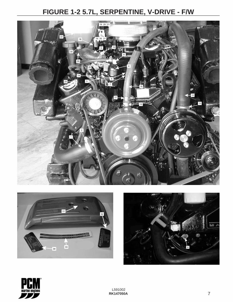
FIGURE 1-2 5.7L, SERPENTINE, V-DRIVE - F/W
1
12
5
4
2
7
9
8
10
6
1315
14
16
17
2019 21
2019 21
28
26
18
29
22
30
25
31
32
3334
36
8L591002
RK147050A
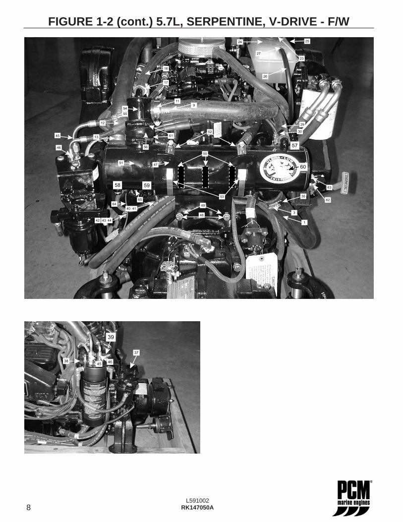
FIGURE 1-2 (cont.) 5.7L, SERPENTINE, V-DRIVE - F/W
303030303061
1
24
23
25
27
9
54
45
46
4140
43 4442
49
55
65
56
47
29
48
50
52
51
62
63
26
30
57
58 59
53
60
16
17
11
35
3
13
12
64
37
38
39
4546
9L591002
RK147050A
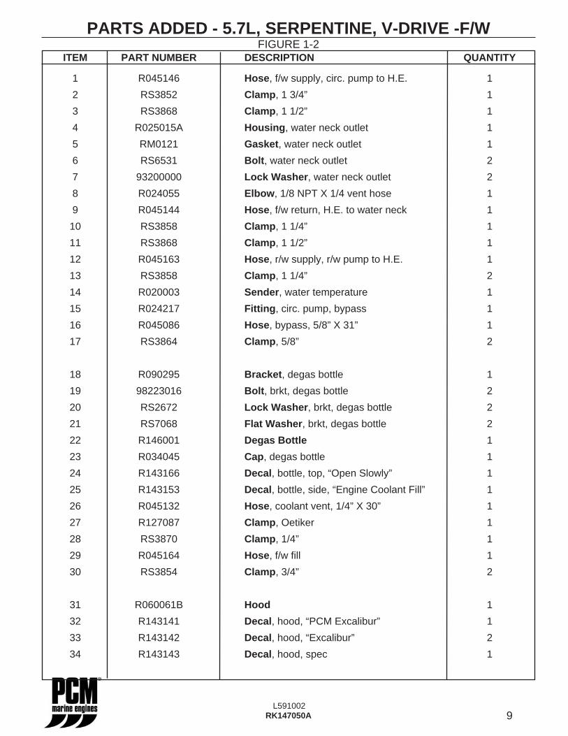
ITEM PART NUMBER DESCRIPTION QUANTITY
1 R045146 Hose, f/w supply, circ. pump to H.E. 1
2 RS3852 Clamp, 1 3/4” 1
3 RS3868 Clamp, 1 1/2” 1
4 R025015A Housing, water neck outlet 1
5 RM0121 Gasket, water neck outlet 1
6 RS6531 Bolt, water neck outlet 2
7 93200000 Lock Washer, water neck outlet 2
8 R024055 Elbow, 1/8 NPT X 1/4 vent hose 1
9 R045144 Hose, f/w return, H.E. to water neck 1
10 RS3858 Clamp, 1 1/4” 1
11 RS3868 Clamp, 1 1/2” 1
12 R045163 Hose, r/w supply, r/w pump to H.E. 1
13 RS3858 Clamp, 1 1/4” 2
14 R020003 Sender, water temperature 1
15 R024217 Fitting, circ. pump, bypass 1
16 R045086 Hose, bypass, 5/8” X 31” 1
17 RS3864 Clamp, 5/8” 2
18 R090295 Bracket, degas bottle 1
19 98223016 Bolt, brkt, degas bottle 2
20 RS2672 Lock Washer, brkt, degas bottle 2
21 RS7068 Flat Washer, brkt, degas bottle 2
22 R146001 Degas Bottle 1
23 R034045 Cap, degas bottle 1
24 R143166 Decal, bottle, top, “Open Slowly” 1
25 R143153 Decal, bottle, side, “Engine Coolant Fill” 1
26 R045132 Hose, coolant vent, 1/4” X 30” 1
27 R127087 Clamp, Oetiker 1
28 RS3870 Clamp, 1/4” 1
29 R045164 Hose, f/w fi ll 1
30 RS3854 Clamp, 3/4” 2
31 R060061B Hood 1
32 R143141 Decal, hood, “PCM Excalibur” 1
33 R143142 Decal, hood, “Excalibur” 2
34 R143143 Decal, hood, spec 1
PARTS ADDED - 5.7L, SERPENTINE, V-DRIVE -F/WFIGURE 1-2
10L591002
RK147050A
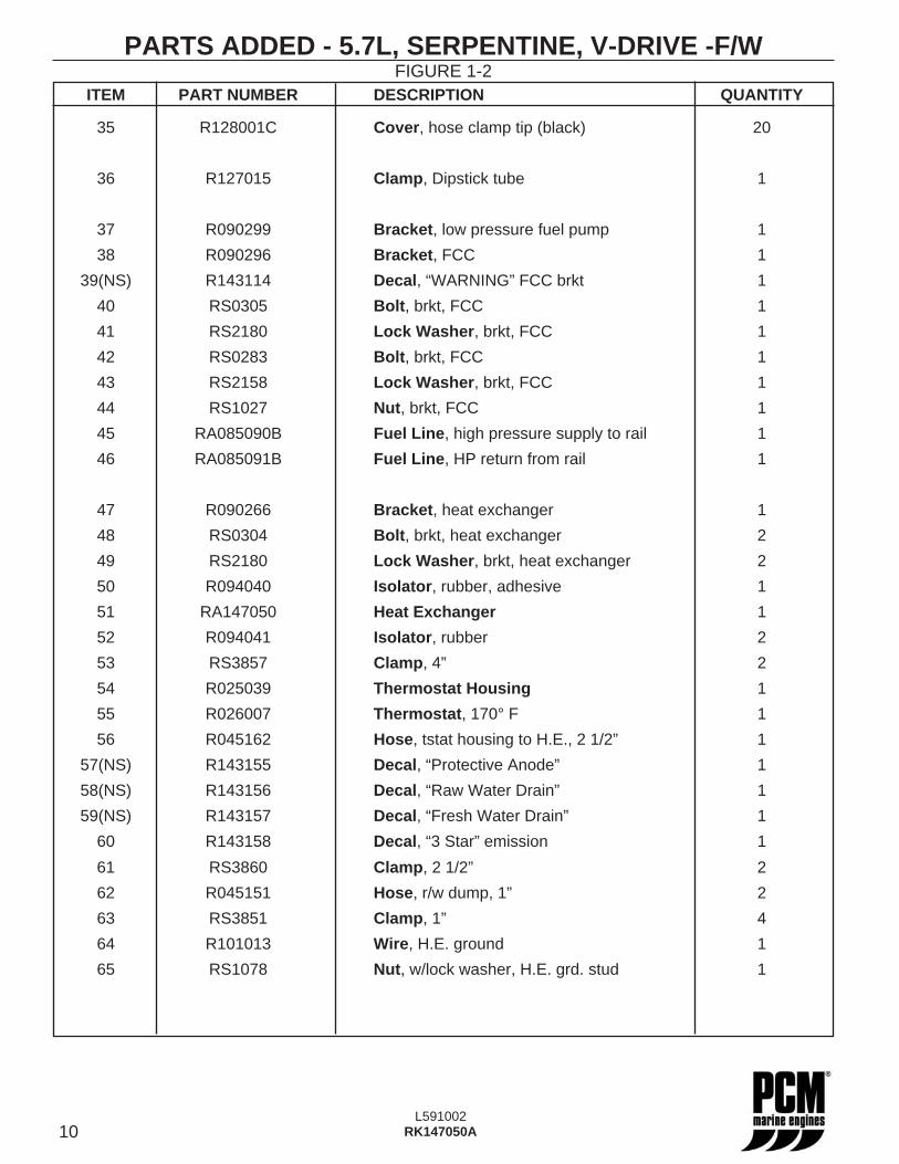
PARTS ADDED - 5.7L, SERPENTINE, V-DRIVE -F/WFIGURE 1-2
ITEM PART NUMBER DESCRIPTION QUANTITY
35 R128001C Cover, hose clamp tip (black) 20
36 R127015 Clamp, Dipstick tube 1
37 R090299 Bracket, low pressure fuel pump 1
38 R090296 Bracket, FCC 1
39(NS) R143114 Decal, “WARNING” FCC brkt 1
40 RS0305 Bolt, brkt, FCC 1
41 RS2180 Lock Washer, brkt, FCC 1
42 RS0283 Bolt, brkt, FCC 1
43 RS2158 Lock Washer, brkt, FCC 1
44 RS1027 Nut, brkt, FCC 1
45 RA085090B Fuel Line, high pressure supply to rail 1
46 RA085091B Fuel Line, HP return from rail 1
47 R090266 Bracket, heat exchanger 1
48 RS0304 Bolt, brkt, heat exchanger 2
49 RS2180 Lock Washer, brkt, heat exchanger 2
50 R094040 Isolator, rubber, adhesive 1
51 RA147050 Heat Exchanger 1
52 R094041 Isolator, rubber 2
53 RS3857 Clamp, 4” 2
54 R025039 Thermostat Housing 1
55 R026007 Thermostat, 170° F 1
56 R045162 Hose, tstat housing to H.E., 2 1/2” 1
57(NS) R143155 Decal, “Protective Anode” 1
58(NS) R143156 Decal, “Raw Water Drain” 1
59(NS) R143157 Decal, “Fresh Water Drain” 1
60 R143158 Decal, “3 Star” emission 1
61 RS3860 Clamp, 2 1/2” 2
62 R045151 Hose, r/w dump, 1” 2
63 RS3851 Clamp, 1” 4
64 R101013 Wire, H.E. ground 1
65 RS1078 Nut, w/lock washer, H.E. grd. stud 1
11L591002
RK147050A
FWC KIT INSTALLATION - V-DRIVE
1. Disconnect the negative battery terminal cable.
2. Remove the hood (Figure 1-1, item 19) from the engine. The hood is not required to complete the installation. Save the hood retention nuts for installation of the new hood later in this procedure.
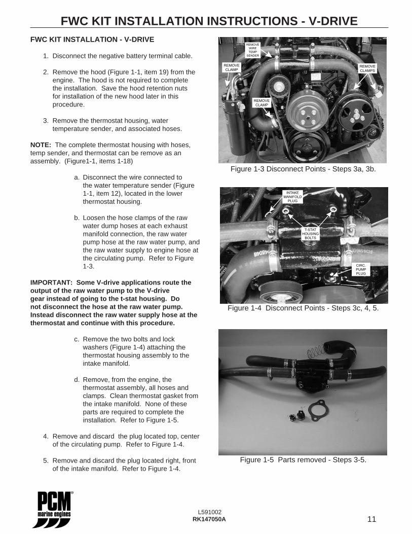
3. Remove the thermostat housing, water temperature sender, and associated hoses.
NOTE: The complete thermostat housing with hoses, temp sender, and thermostat can be remove as an assembly. (Figure1-1, items 1-18)
a. Disconnect the wire connected to the water temperature sender (Figure 1-1, item 12), located in the lower thermostat housing.
b. Loosen the hose clamps of the raw water dump hoses at each exhaust manifold connection, the raw water pump hose at the raw water pump, and the raw water supply to engine hose at the circulating pump. Refer to Figure 1-3.
IMPORTANT: Some V-drive applications route the output of the raw water pump to the V-drive gear instead of going to the t-stat housing. Do not disconnect the hose at the raw water pump. Instead disconnect the raw water supply hose at the thermostat and continue with this procedure.
c. Remove the two bolts and lock washers (Figure 1-4) attaching the thermostat housing assembly to the intake manifold.
d. Remove, from the engine, the thermostat assembly, all hoses and clamps. Clean thermostat gasket from the intake manifold. None of these parts are required to complete the installation. Refer to Figure 1-5.
4. Remove and discard the plug located top, center of the circulating pump. Refer to Figure 1-4.
5. Remove and discard the plug located right, front of the intake manifold. Refer to Figure 1-4.
FWC KIT INSTALLATION INSTRUCTIONS - V-DRIVE
T-STAT
HOUSING
BOLTS
CIRC.
PUMP
PLUG
INTAKE
MANIFOLD
PLUG
REMOVE
CLAMPS
REMOVE
CLAMP
REMOVE
CLAMP
REMOVE
WIRE
TEMP
SENDER
Figure 1-3 Disconnect Points - Steps 3a, 3b.
Figure 1-4 Disconnect Points - Steps 3c, 4, 5.
Figure 1-5 Parts removed - Steps 3-5.
12L591002
RK147050A
FWC KIT INSTALLATION INSTRUCTIONS - V-DRIVE
DEGAS
BOTTLE
MOUNT
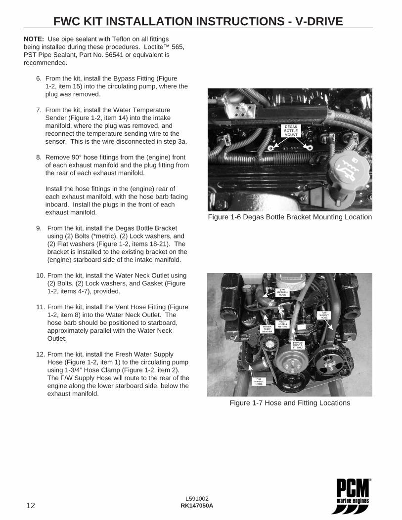
Figure 1-6 Degas Bottle Bracket Mounting Location
Figure 1-7 Hose and Fitting Locations
NOTE: Use pipe sealant with Tefl on on all fi ttings being installed during these procedures. Loctite™ 565, PST Pipe Sealant, Part No. 56541 or equivalent is recommended.
6. From the kit, install the Bypass Fitting (Figure 1-2, item 15) into the circulating pump, where the plug was removed.
7. From the kit, install the Water Temperature Sender (Figure 1-2, item 14) into the intake manifold, where the plug was removed, and reconnect the temperature sending wire to the sensor. This is the wire disconnected in step 3a.
8. Remove 90° hose fi ttings from the (engine) front of each exhaust manifold and the plug fi tting from the rear of each exhaust manifold.
Install the hose fi ttings in the (engine) rear of each exhaust manifold, with the hose barb facing inboard. Install the plugs in the front of each exhaust manifold.
9. From the kit, install the Degas Bottle Bracket using (2) Bolts (*metric), (2) Lock washers, and (2) Flat washers (Figure 1-2, items 18-21). The bracket is installed to the existing bracket on the (engine) starboard side of the intake manifold.
10. From the kit, install the Water Neck Outlet using (2) Bolts, (2) Lock washers, and Gasket (Figure 1-2, items 4-7), provided.
11. From the kit, install the Vent Hose Fitting (Figure 1-2, item 8) into the Water Neck Outlet. The hose barb should be positioned to starboard, approximately parallel with the Water Neck Outlet.
12. From the kit, install the Fresh Water Supply Hose (Figure 1-2, item 1) to the circulating pump using 1-3/4” Hose Clamp (Figure 1-2, item 2). The F/W Supply Hose will route to the rear of the engine along the lower starboard side, below the exhaust manifold.
F/W
SUPPLY
HOSE
BYPASS
HOSE &
FITTING
F/W
RETURN
HOSE
VENT
HOSE &
FITTINGWATER
TEMP
SENDER
R/W
SUPPLY
HOSE
13L591002
RK147050A
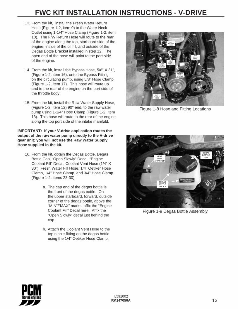
13. From the kit, install the Fresh Water Return Hose (Figure 1-2, item 9) to the Water Neck Outlet using 1-1/4” Hose Clamp (Figure 1-2, item 10). The F/W Return Hose will route to the rear of the engine along the top, starboard side of the engine, inside of the oil fi ll, and outside of the Degas Bottle Bracket installed in step 12. The open end of the hose will point to the port side of the engine.
14. From the kit, install the Bypass Hose, 5/8” X 31”, (Figure 1-2, item 16), onto the Bypass Fitting on the circulating pump, using 5/8” Hose Clamp (Figure 1-2, item 17). This hose will route up and to the rear of the engine on the port side of the throttle body.
15. From the kit, install the Raw Water Supply Hose, (Figure 1-2, item 12) 90° end, to the raw water pump using 1-1/4” Hose Clamp (Figure 1-2, item 13). This hose will route to the rear of the engine along the top port side of the intake manifold.
IMPORTANT: If your V-drive application routes the output of the raw water pump directly to the V-drive gear unit; you will not use the Raw Water Supply Hose supplied in the kit.
16. From the kit, obtain the Degas Bottle, Degas Bottle Cap, “Open Slowly” Decal, “Engine Coolant Fill” Decal, Coolant Vent Hose (1/4” X 30”), Fresh Water Fill Hose, 1/4” Oetiker Hose Clamp, 1/4” Hose Clamp, and 3/4” Hose Clamp (Figure 1-2, items 23-30).
a. The cap end of the degas bottle is the front of the degas bottle. On the upper starboard, forward, outside corner of the degas bottle, above the “MIN”/”MAX” marks, affi x the “Engine Coolant Fill” Decal here. Affi x the “Open Slowly” decal just behind the cap.
b. Attach the Coolant Vent Hose to the top nipple fi tting on the degas bottle using the 1/4” Oetiker Hose Clamp.
FWC KIT INSTALLATION INSTRUCTIONS - V-DRIVE
DEGAS
BOTTLE
DECALS
DEGAS
BOTTLE
CAPVENT
HOSE
ATTACHED
Figure 1-8 Hose and Fitting Locations
Figure 1-9 Degas Bottle Assembly
F/W
SUPPLY
HOSE
BYPASS
HOSE &
FITTING
F/W
RETURN
HOSE
VENT
HOSE &
FITTINGWATER
TEMP
SENDER
R/W
SUPPLY
HOSE
14L591002
RK147050A
c. Attach the Fresh Water Fill Hose to the bottom hose outlet of the degas bottle.
d. Install the Degas Bottle Cap on the Degas Bottle. With the cap towards the front of the engine, route the Coolant Vent Hose down and under the Degas bottle so the end of the hose is toward the front of the engine. Route the vent hose inside of the oil fi ll and attach it to the Vent Hose Fitting on the Water neck Outlet using 1/4” Hose Clamp. (Figure 1-2, item 28) Seat the Degas Bottle on the Degas Bottle Bracket.
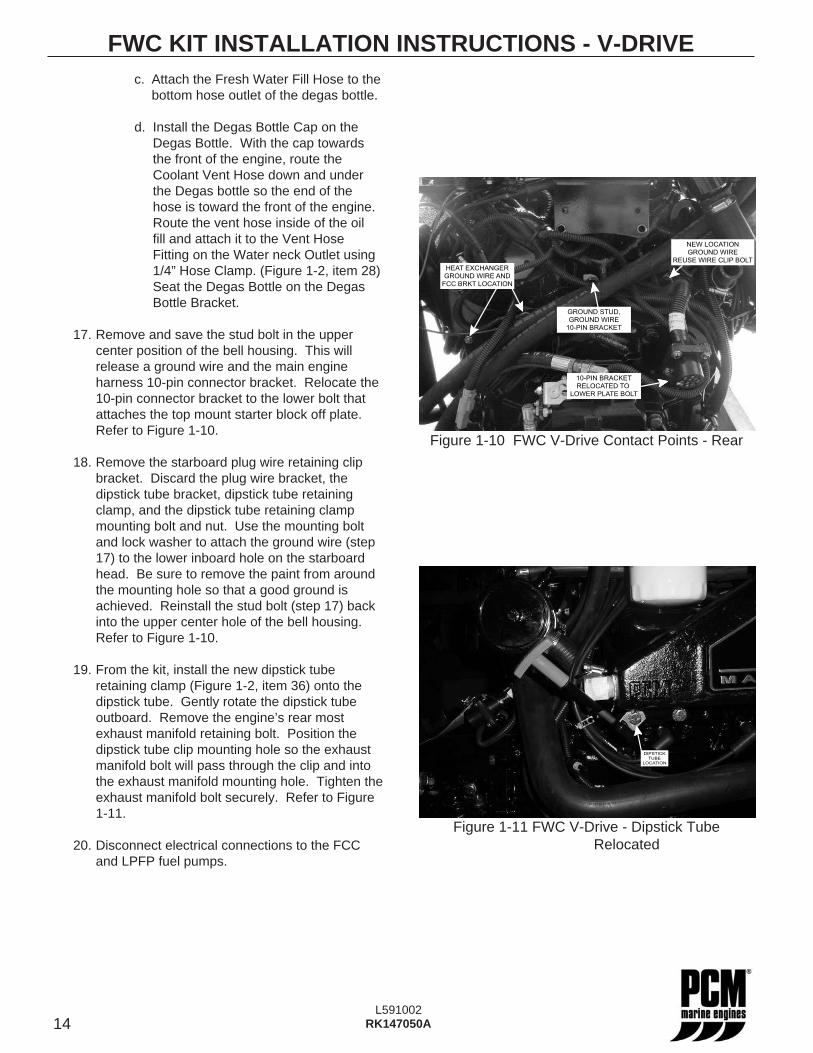
17. Remove and save the stud bolt in the upper center position of the bell housing. This will release a ground wire and the main engine harness 10-pin connector bracket. Relocate the 10-pin connector bracket to the lower bolt that attaches the top mount starter block off plate. Refer to Figure 1-10.
18. Remove the starboard plug wire retaining clip bracket. Discard the plug wire bracket, the dipstick tube bracket, dipstick tube retaining clamp, and the dipstick tube retaining clamp mounting bolt and nut. Use the mounting bolt and lock washer to attach the ground wire (step 17) to the lower inboard hole on the starboard head. Be sure to remove the paint from around the mounting hole so that a good ground is achieved. Reinstall the stud bolt (step 17) back into the upper center hole of the bell housing. Refer to Figure 1-10.
19. From the kit, install the new dipstick tube retaining clamp (Figure 1-2, item 36) onto the dipstick tube. Gently rotate the dipstick tube outboard. Remove the engine’s rear most exhaust manifold retaining bolt. Position the dipstick tube clip mounting hole so the exhaust manifold bolt will pass through the clip and into the exhaust manifold mounting hole. Tighten the exhaust manifold bolt securely. Refer to Figure 1-11.
20. Disconnect electrical connections to the FCC and LPFP fuel pumps.
FWC KIT INSTALLATION INSTRUCTIONS - V-DRIVE
Figure 1-10 FWC V-Drive Contact Points - Rear
DIPSTICK
TUBE
LOCATION
HEAT EXCHANGER
GROUND WIRE AND
FCC BRKT LOCATION
GROUND STUD,
GROUND WIRE
10-PIN BRACKET
NEW LOCATION
GROUND WIRE
REUSE WIRE CLIP BOLT
10-PIN BRACKET
RELOCATED TO
LOWER PLATE BOLT
Figure 1-11 FWC V-Drive - Dipstick Tube Relocated
15L591002
RK147050A
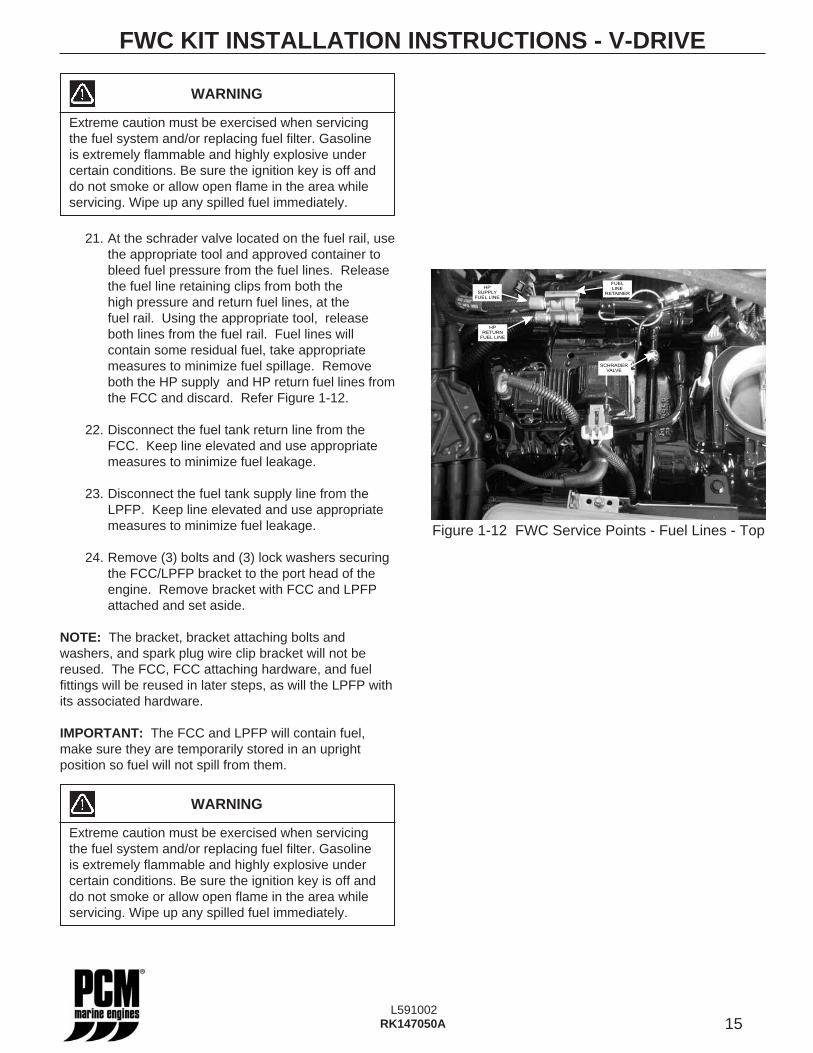
21. At the schrader valve located on the fuel rail, use the appropriate tool and approved container to bleed fuel pressure from the fuel lines. Release the fuel line retaining clips from both the high pressure and return fuel lines, at the fuel rail. Using the appropriate tool, release both lines from the fuel rail. Fuel lines will contain some residual fuel, take appropriate measures to minimize fuel spillage. Remove both the HP supply and HP return fuel lines from the FCC and discard. Refer Figure 1-12.
22. Disconnect the fuel tank return line from the FCC. Keep line elevated and use appropriate measures to minimize fuel leakage.
23. Disconnect the fuel tank supply line from the LPFP. Keep line elevated and use appropriate measures to minimize fuel leakage.
24. Remove (3) bolts and (3) lock washers securing the FCC/LPFP bracket to the port head of the engine. Remove bracket with FCC and LPFP attached and set aside.
NOTE: The bracket, bracket attaching bolts and washers, and spark plug wire clip bracket will not be reused. The FCC, FCC attaching hardware, and fuel fi ttings will be reused in later steps, as will the LPFP with its associated hardware.
IMPORTANT: The FCC and LPFP will contain fuel, make sure they are temporarily stored in an upright position so fuel will not spill from them.
FWC KIT INSTALLATION INSTRUCTIONS - V-DRIVE
WARNING
Extreme caution must be exercised when servicing the fuel system and/or replacing fuel fi lter. Gasoline is extremely fl ammable and highly explosive under certain conditions. Be sure the ignition key is off and do not smoke or allow open fl ame in the area while servicing. Wipe up any spilled fuel immediately.
FUEL
LINE
RETAINER
HP
RETURN
FUEL LINE
HP
SUPPLY
FUEL LINE
SCHRADER
VALVE
Figure 1-12 FWC Service Points - Fuel Lines - Top
16L591002
RK147050A
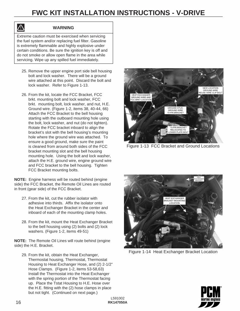
25. Remove the upper engine port side bell housing bolt and lock washer. There will be a ground wire attached at this point. Discard the bolt and lock washer. Refer to Figure 1-13.
26. From the kit, locate the FCC Bracket, FCC brkt. mounting bolt and lock washer, FCC brkt. mounting bolt, lock washer, and nut, H.E. Ground wire. (Figure 1-2, items 38, 40-44, 66) Attach the FCC Bracket to the bell housing starting with the outboard mounting hole using the bolt, lock washer, and nut (do not tighten). Rotate the FCC bracket inboard to align the bracket’s slot with the bell housing’s mounting hole where the ground wire was attached. To ensure a good ground, make sure the paint is cleaned from around both sides of the FCC bracket mounting slot and the bell housing mounting hole. Using the bolt and lock washer, attach the H.E. ground wire, engine ground wire and FCC bracket to the bell housing. Tighten FCC Bracket mounting bolts.
NOTE: Engine harness will be routed behind (engine side) the FCC Bracket, the Remote Oil Lines are routed in front (gear side) of the FCC Bracket.
27. From the kit, cut the rubber isolator with adhesive into thirds. Affi x the isolator onto the Heat Exchanger Bracket in the center and inboard of each of the mounting clamp holes.
28. From the kit, mount the Heat Exchanger Bracket to the bell housing using (2) bolts and (2) lock washers. (Figure 1-2, items 49-51)
NOTE: The Remote Oil Lines will route behind (engine side) the H.E. Bracket.
29. From the kit, obtain the Heat Exchanger, Thermostat housing, Thermostat, Thermostat Housing to Heat Exchanger Hose, and (2) 2-1/2” Hose Clamps. (Figure 1-2, items 53-58,63) Install the Thermostat into the Heat Exchanger with the spring portion of the Thermostat facing up. Place the Tstat Housing to H.E. Hose over the H.E. fi tting with the (2) hose clamps in place but not tight. (Continued on next page.)
FWC KIT INSTALLATION INSTRUCTIONS - V-DRIVE
HEAT EXCHANGER
GROUND WIRE AND
FCC BRKT LOCATION
GROUND STUD,
GROUND WIRE
10-PIN BRACKET
NEW LOCATION
GROUND WIRE
REUSE WIRE CLIP BOLT
10-PIN BRACKET
RELOCATED TO
LOWER PLATE BOLT
WARNING
Extreme caution must be exercised when servicing the fuel system and/or replacing fuel fi lter. Gasoline is extremely fl ammable and highly explosive under certain conditions. Be sure the ignition key is off and do not smoke or allow open fl ame in the area while servicing. Wipe up any spilled fuel immediately.
Figure 1-14 Heat Exchanger Bracket Location
HEAT EXCHANGER
BRACKET MOUNTING
LOCATION
HEAT
EXCHANGER
BRACKET
Figure 1-13 FCC Bracket and Ground Locations
17L591002
RK147050A
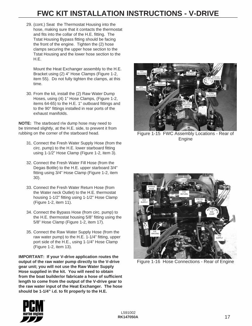
29. (cont.) Seat the Thermostat Housing into the hose, making sure that it contacts the thermostat and fi ts into the collar of the H.E. fi tting. The Tstat Housing Bypass fi tting should be facing the front of the engine. Tighten the (2) hose clamps securing the upper hose section to the Tstat Housing and the lower hose section to the H.E.
Mount the Heat Exchanger assembly to the H.E. Bracket using (2) 4” Hose Clamps (Figure 1-2, item 55). Do not fully tighten the clamps, at this time.
30. From the kit, install the (2) Raw Water Dump Hoses, using (4) 1” Hose Clamps, (Figure 1-2, items 64-65) to the H.E. 1” outboard fi ttings and to the 90° fi ttings installed in rear ports of the exhaust manifolds.
NOTE: The starboard r/w dump hose may need to be trimmed slightly, at the H.E. side, to prevent it from rubbing on the corner of the starboard head.
31. Connect the Fresh Water Supply Hose (from the circ. pump) to the H.E. lower starboard fi tting using 1-1/2” Hose Clamp (Figure 1-2, item 3).
32. Connect the Fresh Water Fill Hose (from the Degas Bottle) to the H.E. upper starboard 3/4” fi tting using 3/4” Hose Clamp (Figure 1-2, item 30).
33. Connect the Fresh Water Return Hose (from the Water neck Outlet) to the H.E. thermostat housing 1-1/2” fi tting using 1-1/2” Hose Clamp (Figure 1-2, item 11).
34. Connect the Bypass Hose (from circ. pump) to the H.E. thermostat housing 5/8” fi tting using the 5/8” Hose Clamp (Figure 1-2, item 17).
35. Connect the Raw Water Supply Hose (from the raw water pump) to the H.E. 1-1/4” fi tting, upper port side of the H.E., using 1-1/4” Hose Clamp (Figure 1-2, item 13).
IMPORTANT: If your V-drive application routes the output of the raw water pump directly to the V-drive gear unit; you will not use the Raw Water Supply Hose supplied in the kit. You will need to obtain from the boat builder/or fabricate a hose of suffi cient length to come from the output of the V-drive gear to the raw water input of the Heat Exchanger. The hose should be 1-1/4” i.d. to fi t properly to the H.E.
FWC KIT INSTALLATION INSTRUCTIONS - V-DRIVE
Figure 1-16 Hose Connections - Rear of Engine
Figure 1-15 FWC Assembly Locations - Rear of Engine
H.E. BRKT.
MOUNTING
BOLTS
10-PIN
RELOCATED
HEAT
EXCHANGER
T-STAT
ASSEMBLYRUBBER
ISOLATOR
LPFP
RELOCATED
FCC
RELOCATED
DIPSTICK
RELOCATED
H.E.
GROUND
R/W
DUMP
R/W
SUPPLY
BYPASS
HOSE
F/W
SUPPLY
F/W
RETURN
F/W FILL
HOSE
18L591002
RK147050A
36. From the kit, use the Nut w/lock washer (Figure 1-2, item 67) to secure the ground wire to the H.E. ground stud.
37. From the kit, affi x decals (Figure 1-2, items 59-62, Figure 1-2 also shows approximate location of the decals) to the Heat Exchanger.
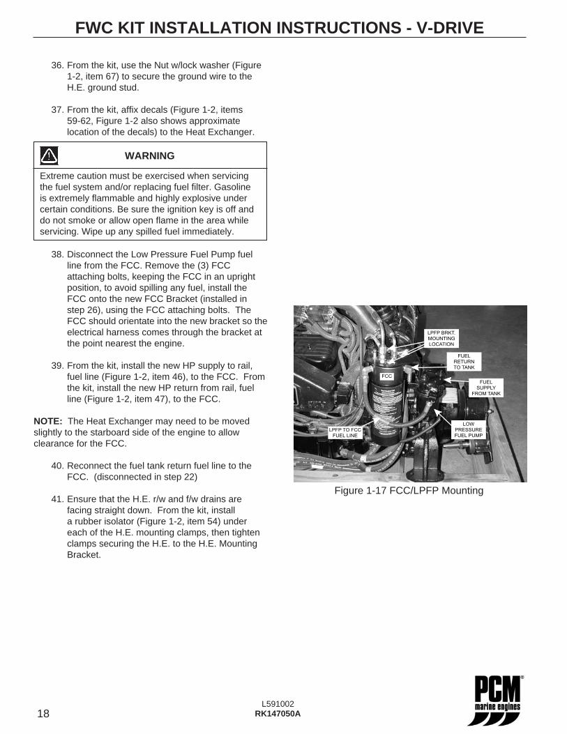
38. Disconnect the Low Pressure Fuel Pump fuel line from the FCC. Remove the (3) FCC attaching bolts, keeping the FCC in an upright position, to avoid spilling any fuel, install the FCC onto the new FCC Bracket (installed in step 26), using the FCC attaching bolts. The FCC should orientate into the new bracket so the electrical harness comes through the bracket at the point nearest the engine.
39. From the kit, install the new HP supply to rail, fuel line (Figure 1-2, item 46), to the FCC. From the kit, install the new HP return from rail, fuel line (Figure 1-2, item 47), to the FCC.
NOTE: The Heat Exchanger may need to be moved slightly to the starboard side of the engine to allow clearance for the FCC.
40. Reconnect the fuel tank return fuel line to the FCC. (disconnected in step 22)
41. Ensure that the H.E. r/w and f/w drains are facing straight down. From the kit, install a rubber isolator (Figure 1-2, item 54) under each of the H.E. mounting clamps, then tighten clamps securing the H.E. to the H.E. Mounting Bracket.
FWC KIT INSTALLATION INSTRUCTIONS - V-DRIVE
WARNING
Extreme caution must be exercised when servicing the fuel system and/or replacing fuel fi lter. Gasoline is extremely fl ammable and highly explosive under certain conditions. Be sure the ignition key is off and do not smoke or allow open fl ame in the area while servicing. Wipe up any spilled fuel immediately.
LOW
PRESSURE
FUEL PUMP
FUEL
SUPPLY
FROM TANK
FUEL
RETURN
TO TANK
LPFP BRKT.
MOUNTING
LOCATION
LPFP TO FCC
FUEL LINE
FCC
Figure 1-17 FCC/LPFP Mounting
19L591002
RK147050A
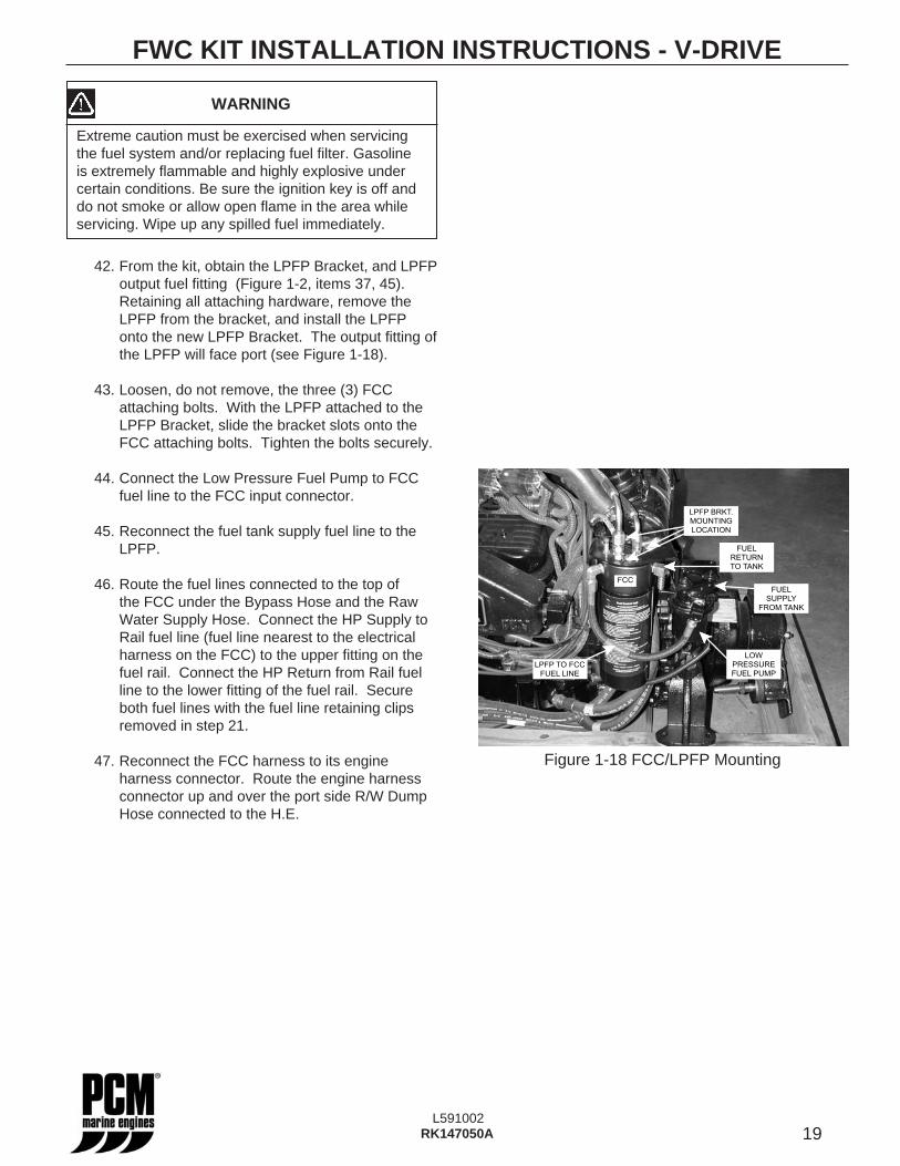
42. From the kit, obtain the LPFP Bracket, and LPFP output fuel fi tting (Figure 1-2, items 37, 45). Retaining all attaching hardware, remove the LPFP from the bracket, and install the LPFP onto the new LPFP Bracket. The output fi tting of the LPFP will face port (see Figure 1-18).
43. Loosen, do not remove, the three (3) FCC attaching bolts. With the LPFP attached to the LPFP Bracket, slide the bracket slots onto the FCC attaching bolts. Tighten the bolts securely.
44. Connect the Low Pressure Fuel Pump to FCC fuel line to the FCC input connector.
45. Reconnect the fuel tank supply fuel line to the LPFP.
46. Route the fuel lines connected to the top of the FCC under the Bypass Hose and the Raw Water Supply Hose. Connect the HP Supply to Rail fuel line (fuel line nearest to the electrical harness on the FCC) to the upper fi tting on the fuel rail. Connect the HP Return from Rail fuel line to the lower fi tting of the fuel rail. Secure both fuel lines with the fuel line retaining clips removed in step 21.
47. Reconnect the FCC harness to its engine harness connector. Route the engine harness connector up and over the port side R/W Dump Hose connected to the H.E.
FWC KIT INSTALLATION INSTRUCTIONS - V-DRIVE
WARNING
Extreme caution must be exercised when servicing the fuel system and/or replacing fuel fi lter. Gasoline is extremely fl ammable and highly explosive under certain conditions. Be sure the ignition key is off and do not smoke or allow open fl ame in the area while servicing. Wipe up any spilled fuel immediately.
LOW
PRESSURE
FUEL PUMP
FUEL
SUPPLY
FROM TANK
FUEL
RETURN
TO TANK
LPFP BRKT.
MOUNTING
LOCATION
LPFP TO FCC
FUEL LINE
FCC
Figure 1-18 FCC/LPFP Mounting
20L591002
RK147050A
48. Reconnect the LPFP harness to its engine harness connector. Route the engine side of the harness under the engine oil and transmission fl uid hoses.
49. From the kit, affi x FCC “Warning” decal on the top of the FCC Bracket. (Figure 1-2, item 39)
50. Remove the engine block drain plugs and drain any remaining water from the engine block. Reinstall block drain plugs.
51. Make sure that all drain plugs are properly installed.
FILLING FRESH-WATER COOLING SYSTEM
A new extended life engine coolant known as DEX-COOL™ is recommended for use in your engine. It is imperative to note the following about DEX-COOL™ engine coolant:
• IT IS PINK IN COLOR TO DISTINGUISH IT FROM CONVENTIONAL COOLANT.
• THE SERVICE CHANGE INTERVAL ON ENGINES BUILT WITH DEX-COOL™ IS 5 YEARS.
• TO MAINTAIN FULL CORROSION PROTECTION DURABILITY, DEX-COOL™ MUST NOT BE MIXED WITH CONVENTIONAL (CONTAINING SILICATE) ENGINE COOLANTS.
• DEX-COOL™ IS AN ETHYLENE GLYCOL BASED PRODUCT, THEREFORE, BOIL AND FREEZE PROTECTION ARE MEASURED IN THE SAME FASHION AS CONVENTIONAL COOLANTS.
TO FULLY REALIZE ITS MANY ADVANTAGES, DEX-COOL™ MUST NEVER BE MIXED WITH CONVENTIONAL COOLANTS.
FWC KIT INSTALLATION INSTRUCTIONS - V-DRIVEDEX-COOL™ can become contaminated by inadvertently topping-off with conventional coolant, adding conventional coolant to the system or even if fi ll/drain containers are shared between coolants. If contamination occurs, the cooling system must be immediately drained and fl ushed, and refi lled with DEX-COOL™. No short-term damage will occur, however, the service interval will be reduced from 5 years to 2 years.
The fresh-water cooling side of the cooling system must be fi lled with a 50/50 mixture of DEX-COOL™ (or equivalent, which meets GM6277M) extended life antifreeze and water solution.
IMPORTANT: More than 50% antifreeze solution can contribute to an overheating condition.
52. Reconnect negative terminal of the battery.
53. Remove the pressure cap from the Degas Bottle.
54. Prepare 5 gallons of DEX-COOL™ 50/50 solution. Fill the system with antifreeze solution until the system is fi lled. Degas Bottle will be full to the top of the bottle.
55. Prime the fuel system. Turn the ignition key to the ON position for 5 seconds, turn the key OFF for 10 seconds, and repeat 1-3 times.
56. Start the engine and operate at idle speed (800-1000 RPM) to purge any air from the system. When the coolant level remains constant, install the pressure cap on the Degas Bottle.
WARNING
Extreme caution must be exercised when servicing the fuel system and/or replacing fuel fi lter. Gasoline is extremely fl ammable and highly explosive under certain conditions. Be sure the ignition key is off and do not smoke or allow open fl ame in the area while servicing. Wipe up any spilled fuel immediately.
WARNING
Make sure that there are no fuel leaks before closing the engine hatch.
WARNING
Visually inspect unit for fuel leaks before operating the engine. If fuel leaks are present, DO NOT operate the engine, repair immediately.
21L591002
RK147050A
57. Continue to run the engine until it reaches normal operating temperature. Check for fuel leaks, oil leaks, fresh water coolant leaks, and raw water leaks at all fi ttings and connections. Correct all leaks, as required.
NOTICE: It is not necessary to remove pressure cap to check coolant levels. Check Degas Bottle daily and keep fi lled to the ‘MAX” level indicated on the bottle.
58. Continue to run the engine at normal operating temperature. Check the Degas Bottle for the proper level and add coolant if necessary.
59. From the kit, install the Hose Clamp Covers, (Figure 1-2, item 35), on all hose clamp ends.
60. From the kit, affi x decals to the new hood (Figure 1-2, items 31-34) and attach the hood to the engine with the retention nuts removed in step 2.
Installation of the Fresh Water Cooling Kit on a V-Drive application is complete.
FWC KIT INSTALLATION INSTRUCTIONS - V-DRIVE
WARNING
Make sure that there are no fuel leaks before closing the engine hatch.
WARNING
Do not remove cooling system fi ller cap when the engine is hot. Allow the engine to cool and then remove the pressure cap slowly, allowing the pressure to vent. Hot coolant, under pressure, may discharge violently and cause severe burns.
22L591002
RK147050A
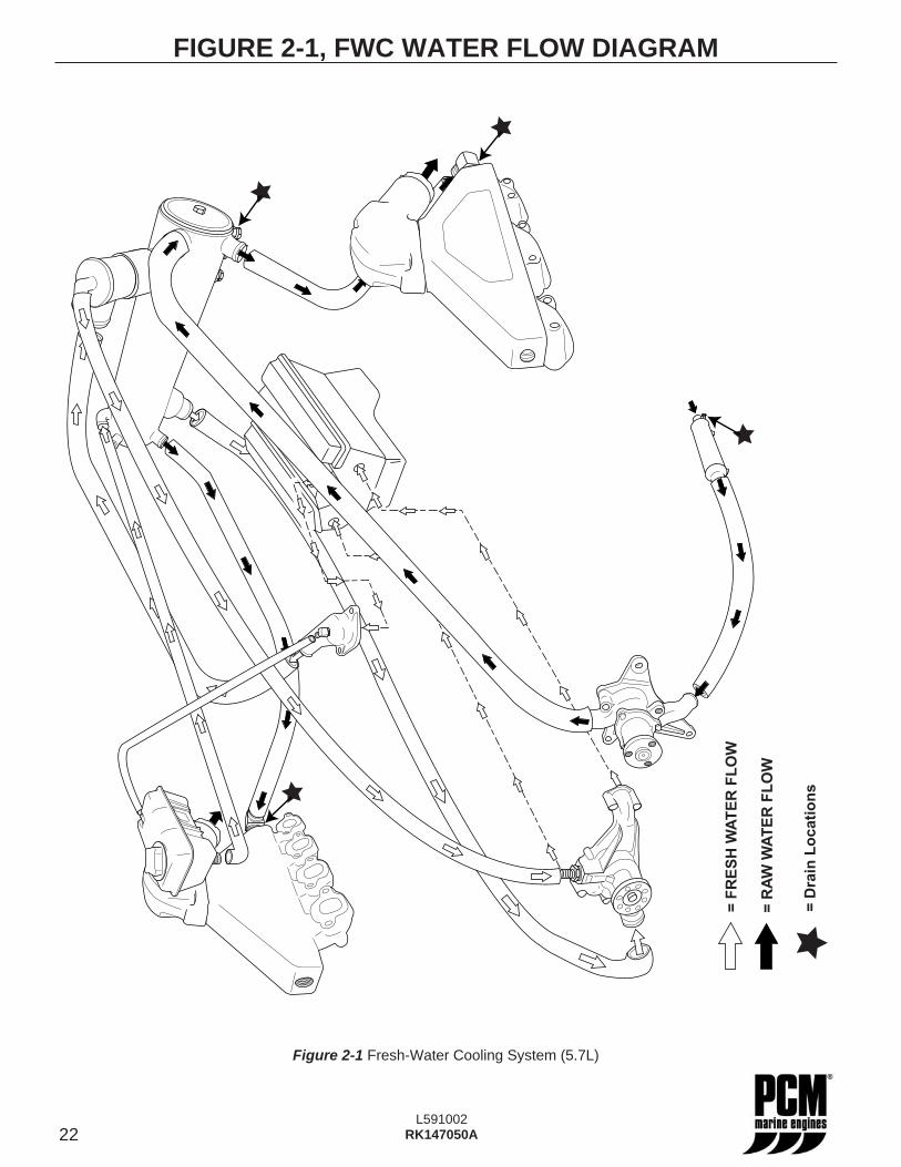
Figure 2-1 Fresh-Water Cooling System (5.7L)
FIGURE 2-1, FWC WATER FLOW DIAGRAM
= R
AW
WA
TE
R F
LO
W
= F
RE
SH
WA
TE
R F
LO
W
= D
rain
Lo
cati
on
s