Embed Size (px)
Citation preview

2004 2.8L (LK5), 3.5L (L52) ENGINE DIAGNOSTIC PARAMETERS
2004file12.doc
SENSED PARAMETER
FAULT CODE
MONITOR STRATEGY DESCRIPTION
MALFUNCTION CRITERIA AND THRESHOLD VALUE(S)
SECONDARY PARAMETERS AND ENABLE CONDITIONS
TIME LENGTH AND FREQUENCY
MIL
ILLUMINATION TYPE
Cam Phaser Solenoid Circuit Fault
P0013 Checks the cam phaser solenoid circuit for electrical integrity
Output state invalid 10/20 counts 100 msec/count Continuous check
DTC Type B
VCP System Performance (VCP = variable cam phaser)
P0014 Detects a VCP system error by comparing desired and actual VCP position through all operating ranges of VCP control
Actual position/desired position difference is greater than 3.75 degrees when VCP is commanded and stabilization time (based on oil temp model) of 3 secs is met
No cam phaser DTCs Engine speed > 1350 RPM VCP is commanded VCP commanded position is stable within 0.9 degrees for 1 sec System voltage ≥ 11 V
135/150 counts 100 msec/count Continuous check when VCP is commanded
DTC Type B
Camshaft Position Sensor-A Bank-1 Correlation (Non-Encoded Cam Sensor)
P0016 Detects cam to crank misalignment by monitoring if cam sensor pulse occurs during the incorrect crank position (Cam to Crank Correlation Diagnostic)
Cam sensor pulse occurs outside crank MedRes region: KaEPSD_Cnt_NE_CamPerf_Region_1 = 2 KaEPSD_Cnt_NE_CamPerf_Region_2 = 3 The crank MedRes region is a certain number of crank sensor pulses. ECM throughput prohibits using every crank sensor pulse. Typical crank MedRes region is twice per cylinder, but varies in each engine.
IF[ CAM_TYPE = NON_ENCODED_CAM AND CAM_TYPE ≠ CSI_CAM AND CKP_MedRes_Active = TRUE AND Crank_Sync_Flag = Crank_In_Sync AND Fault_Pending[CMP_CKT_Perf] = FALSE AND Fault_Active[CMP_CKT] = FALSE AND Fault_Active[CKP_SnsrA_Ckt] = FALSE AND Fault_Active[CKP_SnsrA_Perf] = FALSE AND Fault_Active[CKP_SnsrB_Ckt] = FALSE AND Fault_Active[CKP_SnsrB_Perf] = FALSE AND Fault_Active[CKP_SnsrAB_Corr] = FALSE ]THEN ENABLE DIAGNOSTIC ELSE DISABLE DIAGNOSTIC ENDIF
8 cam pulses out of the last 10 cam sensor pulses are outside malfunction criteria Continuous check
DTC Type B
2004file12.doc 1

2004 2.8L (LK5), 3.5L (L52) ENGINE DIAGNOSTIC PARAMETERS
2004file12.doc
SENSED PARAMETER
FAULT CODE
MONITOR STRATEGY DESCRIPTION
MALFUNCTION CRITERIA AND THRESHOLD VALUE(S)
SECONDARY PARAMETERS AND ENABLE CONDITIONS
TIME LENGTH AND FREQUENCY
MIL
ILLUMINATION TYPE
Camshaft Position Sensor-B Bank-1 Correlation (Encoded Cam Sensor)
P0017 Detects cam to crank misalignment by monitoring if cam sensor pulse occurs during the incorrect crank position (Cam to crank Correlation Diagnostic)
Cam sensor pulse < 97.63 degrees or > 113.22 degrees before LoRes crank pulse
IF[ CAM_TYPE = ENCODED_CAM AND CAM_TYPE ≠ CSI_CAM AND Engine_Running = TRUE AND Crank_Sync_Flag = Crank_In_Sync AND Cam_Phaser_Position = PARKED AND Fault_Pending[CMP_CKT_Perf] = FALSE AND Fault_Active [CMP_CKT] = FALSE AND Fault_Active [CKP_SnsrA_Ckt] = FALSE AND Fault_Active [CKP_SnsrA_Perf] = FALSE AND Fault_Active [CKP_SnsrB_Ckt] = FALSE AND Fault_Active [CKP_SnsrB_Perf] = FALSE AND Fault_Active [CKP_SnsrAB_Corr] = FALSE]THEN ENABLE DIAGNOSTIC ELSE DISABLE DIAGNOSTIC ENDIF
25 out of the last 35 cam rotations occur with 2 cam sensor pulses outside of malfunction criteria window Continuous check
DTC Type B
HO2S Heater Control Circuit Bank 1 Sensor 1
P0030 Output state invalid Circuit fault indicated 11 V < System voltage < 18 V Engine speed > 425 RPM
10 fails out of 12 samples Continuous check
DTC Type B
HO2S Heater Control Circuit Bank 1 Sensor 2
P0036 Output state invalid Circuit fault indicated 11 V < System voltage < 18 V Engine speed > 425 RPM
10 fails out of 12 samples Continuous check
DTC Type B
MAP/MAF/Throttle Position Correlation
P0068 Detect when manifold absolute pressure and measured airflow do not match estimated engine airflow as established by the TPS
1. Difference between measured MAP and estimated MAP < 25 kPa
2. Difference between measured MAF and estimated MAF < 25 grams/sec
Engine running No PCM processor, throttle actuation DTCsBoth TPS circuits DTCs are set
187.5 msec Continuous in the main processor
DTC Type A
Mass Airflow (MAF) Sensor Performance
P0101 Determines if the MAF sensor is stuck within the normal operating range
1. Filtered airflow error > 10 grams/sec
2. Filtered manifold pressure 2 error > 20 kPa
3. Filtered throttle error < 350 kPa grams/sec
No MAF circuit, MAP circuit, EGR, ECT circuit, IAT circuit, crank sensor DTCs 400 RPM < Engine speed 70°C < ECT < 125°C -7°C < IAT < 125°C
Immediate Frequency: 12.5 msec loop Continuous check
DTC Type B
MAF Sensor Circuit Low Frequency
P0102 Detects a continuous short to low or open in either the signal circuit or the MAF sensor.
MAF sensor signal < 100 Hz Engine run time > 5 secs Engine speed > 500 RPM System voltage > 11 V Enable criteria stable time > 2.5 secs
30/40 counts 80 counts/sec Continuous check
DTC Type B
2004file12.doc 2

2004 2.8L (LK5), 3.5L (L52) ENGINE DIAGNOSTIC PARAMETERS
2004file12.doc
SENSED PARAMETER
FAULT CODE
MONITOR STRATEGY DESCRIPTION
MALFUNCTION CRITERIA AND THRESHOLD VALUE(S)
SECONDARY PARAMETERS AND ENABLE CONDITIONS
TIME LENGTH AND FREQUENCY
MIL
ILLUMINATION TYPE
MAF Sensor Circuit High Frequency
P0103 Detects a continuous short to high in either the signal circuit or the MAF sensor.
MAF sensor signal > 11000 Hz Engine run time > 5 secs Engine speed > 500 RPM System voltage > 11 V Enable criteria stable time > 2.5 secs
30/40 counts 80 counts/sec Continuous check
DTC Type B
Manifold Absolute Pressure (MAP) Sensor 1 Performance
P0106 Determines if the MAP sensor is stuck within the normal operating range.
1. Filtered manifold pressure 1 error > 20 kPa
2. Filtered manifold pressure 2 error > 20 kPa
3. Filtered throttle error < 350 kPa grams/sec
No MAF circuit, MAP circuit, EGR, ECT circuit, IAT circuit, crank sensor DTCs 400 RPM < Engine speed 70°C < ECT < 125°C -7°C < IAT < 125°C
Immediate Frequency: 12.5 msec loop Continuous check
DTC Type B
MAP Circuit Low Input P0107 Detects a continuous short to low or open in either the signal circuit or the MAP sensor.
MAP < 1.0% of 5 V reference No TPS, 5 V reference DTCs Controller State = RUN [(TPS ≥ 0% & Engine speed ≤ 1100 RPM) or (TPS ≥ 9.9% & Engine speed > 1100 RPM)]
30/40 counts 20 counts/sec Continuous check
DTC Type B
MAP Circuit High Input P0108 Detects a continuous short to high or open in either the signal circuit or the MAP sensor.
MAP > 98.0% of 5 V reference No TPS, 5 V reference DTCs Controller State = RUN Engine run time > table value based on start-up coolant temperature [(TPS < 89.9% & Engine speed ≤ 1000 RPM) or (TPS < 97.5% & Engine speed > 1000 RPM)]
320/400 counts 80 counts/sec Continuous check
DTC Type B
IAT Sensor Circuit Low Voltage
P0112 This DTC determines if the IAT sensor is shorted low by checking for an IAT sensor resistance below a threshold
IAT resistance < 25 Ω No ECT, VSS DTCs ECT < 110°C VSS >= 40 KPH Engine run time > 10 sec
10/20 counts 4 counts/sec Continuous check
DTC Type B
IAT Sensor Circuit High Voltage
P0113 Determines if the IAT sensor is shorted high by checking for an IAT sensor resistance above a threshold
IAT resistance > 1800000 Ω No ECT, VSS, MAF DTCs set ECT ≥ 50°C VSS < 1.6 KPH MAF < 12 grams/sec Engine run time > 10 sec
10/20 counts 4 counts/sec Continuous check
DTC Type B
ECT Sensor Circuit Low Voltage
P0117 Determines if the ECT sensor is shorted low by checking for an ECT sensor resistance below a threshold
ECT resistance < 25 Ω No IAT DTCs IAT < 70 °C or Engine run time > 10 sec
10/100 counts 1 count/sec Continuous check
DTC Type B
ECT Sensor Circuit High Voltage
P0118 Determines if the ECT sensor is shorted high by checking for an ECT sensor resistance above a threshold
ECT resistance > 1800000 Ω No IAT DTCs IAT > -7 °C or Engine run time > 60 sec
10/100 counts 1 count/sec Continuous check
DTC Type B
Throttle Position (TP) Sensor 1 Circuit
P0120 Detects a continuous or intermittent short or open in TP sensor #1 circuit
0.275 V > TPS > 4.725 V Ignition in unlock/accessory, run or crank System voltage>5.23 V No PCM processor, 5 V reference DTCs
20/40 counts; 10 counts continuous; 12.5 msec /count in the motor processor
DTC Type A
2004file12.doc 3

2004 2.8L (LK5), 3.5L (L52) ENGINE DIAGNOSTIC PARAMETERS
2004file12.doc
SENSED PARAMETER
FAULT CODE
MONITOR STRATEGY DESCRIPTION
MALFUNCTION CRITERIA AND THRESHOLD VALUE(S)
SECONDARY PARAMETERS AND ENABLE CONDITIONS
TIME LENGTH AND FREQUENCY
MIL
ILLUMINATION TYPE
Throttle Position (TP) Sensor 1 Performance
P0121 Determines if the TP sensor is stuck within the normal operating range
1. Filtered throttle error > 350 kPa grams/sec
2. Filtered manifold pressure 2 error < 20 kPa
No MAF circuit, MAP circuit, EGR, ECT circuit, IAT circuit, crank sensor DTCs 400 RPM < Engine speed 70°C < ECT < 125°C -7°C < IAT < 125°C
Immediate Frequency: 12.5 msec loop Continuous
DTC Type B
Engine Coolant Temperature (ECT) Insufficient for Closed Loop Fuel Control
P0125 Detects if the engine coolant temperature rises too slowly due to an ECT sensor or cooling system fault
Actual accumulated airflow > predicted accumulated airflow and engine coolant temperature > -7°C Airflow is accumulated every sec if 10 grams/sec < MAF < 75 grams/sec
No MAF, IAT, VSS, ECT circuit DTCs Start up ECT < 75°C Minimum average airflow > 30 grams/sec VSS > 5 MPH for 1 kilometer 30 secs < Engine run time < 1800 secs IAT ≥ 7 °C
30 secs 1 sec loop Frequency: Once per ignition cycle
DTC Type B
Engine Coolant Temperature (ECT) Below Thermostat Regulating Temperature
P0128 Detects if the engine coolant temperature rises too slowly due to an ECT sensor or cooling system fault
Actual accumulated airflow > predicted accumulated airflow and engine coolant temperature > 80°C Airflow is accumulated every sec if 20 grams/sec < MAF < 75 grams/sec
No MAF, IAT, VSS, ECT circuit DTCs Start up ECT < 80 °C Minimum average airflow > 5 grams/sec VSS > 5 MPH for 1 kilometer 30 secs < Engine run time < 1800 secs IAT ≥ -7 °C
30 secs 1 sec loop Frequency: Once per ignition cycle
DTC Type B
HO2S Closed Loop Rationality (bank 1 sensor 1)
P0130 Determines if the O2 sensor voltage is not meeting the voltage criteria to enable closed loop fueling
Closed loop fuel control O2 sensor Ready flag set to “Not Ready”. O2 sensor voltage must be > 550 mV or < 350 mV for 10 counts to set closed loop fuel O2 ready flag. Once set to “Ready,” the O2 sensor voltage cannot be > 350 mV and < 550 mV for > 120 secs or the O2 ready flag will be reset to “Not Ready”.
No injector, MAF, ETC, TPS, MAP, ECT, HO2S Bank 1 Sensor 1 DTCs Engine run time > 200 secs Coolant temp > 70 °C 11 V < System voltage < 18 V Traction control not active Catalyst protection mode not active 1000 RPM ≤ Engine speed ≤ 3400 RPM 10.0 grams/sec ≤ MAF ≤ 50.0 grams/sec Decel fuel cut off not active Power enrichment not active Engine metal overtemp not active Above conditions must be met for 2 secs
400 /500 counts 100 msec/count Continuous check
DTC Type B
HO2S Circuit Low Voltage (bank 1 sensor 1)
P0131 Determines if the O2 sensor or circuit is shorted to low by checking for a lean condition.
O2 sensor voltage < 50 mV OR O2 sensor voltage < 550 mV while in power enrichment
No injector, MAF, ETC, TPS, MAP, ECT, IAT, evap DTCsCatalyst diagnostic test not active Traction control not active Fuel level > 10% 11 V < System voltage < 18 V Lean Test Closed Loop Fuel Enabled 14.5 ≤ Air/Fuel ratio ≤ 14.8 15% ≤ TP ≤ 50 % Above conditions must be met for 2 secs Lean in PE Test Power enrichment mode enabled Above conditions must be met for 2 secs
Lean Test 950/1000 counts 10 counts/sec Continuous check Lean in PE Test 95/100 counts 10 counts/sec Runs during each occurrence of PE
DTC Type B
2004file12.doc 4

2004 2.8L (LK5), 3.5L (L52) ENGINE DIAGNOSTIC PARAMETERS
2004file12.doc
SENSED PARAMETER
FAULT CODE
MONITOR STRATEGY DESCRIPTION
MALFUNCTION CRITERIA AND THRESHOLD VALUE(S)
SECONDARY PARAMETERS AND ENABLE CONDITIONS
TIME LENGTH AND FREQUENCY
MIL
ILLUMINATION TYPE
HO2S Circuit High Voltage (bank 1 sensor 1)
P0132 Determines if the O2 sensor or circuit is shorted to high by checking for a rich condition.
O2 sensor voltage > 1000 mV OR O2 sensor voltage > 350 mV while in DFCO
No injector, MAF, ETC, TPS, MAP, ECT, IAT, evap DTCsCatalyst diagnostic test not active Traction control not active 11 V < System voltage < 18 V Fuel level > 10% Rich Test Closed loop fuel enabled 14.5 ≤ Air/Fuel ratio ≤ 14.8 0% ≤ TP ≤ 50 % Above conditions must be met for 2 secs Rich in DFCO Test Decel fuel cut-off mode enabled Above conditions must be met for 2 secs
Rich Test 140/150 counts 10 counts/sec Continuous check Rich in DFCO Test 95/100 counts 10 counts/sec Runs during each occurrence of DFCO
DTC Type B
HO2S Circuit Slow Response (bank 1 sensor 1)
P0133 Determines if the O2 sensor functioning properly by checking its response time.
O2 sensor average transition time: L/R > 75msec R/L > 135 msec for automatic R/L > 120 msec for manual 350 mV < O2 voltage < 650 mV Note that P0133 is deficient for 2004 model year (L52 and LK5 GMT355) at 2.7x NOx standard
No misfire, injector, MAF, ETC, TPS, evap, IAT, MAP, ECT DTC's set Catalyst diagnostic test not active Closed loop fuel enabled Traction control not active No injectors are disabled Fuel level > 10% 11 V < System voltage < 18 V Engine run time > 200 secs ECT > 70°C 1000 RPM < Engine speed< 3500 RPM 15.0 grams/sec < MAF < 50.0 grams/sec TP ≥ 5 % BLM cell number = 4, 5, 6, 8, 9, or 13 Transmission not in park, reverse or neutral Above conditions met for 2 secs
60 secs Once per key cycle
DTC Type B
HO2S Circuit Insufficient Activity (bank 1 sensor 1)
P0134 Determines if the O2 sensor or the O2 sensor circuit has developed an open.
400 mV< O2 sensor voltage < 500 mV No injector, MAF, ETC, TPS, evap, IAT, MAP, ECT , front O2 heater DTC's set Catalyst diagnostic test not active Traction control not active 11 V < System voltage < 18 V Engine run time > 200 secs Minimum 3 occurrences of a delta TP sensor > 1 % during diagnostic test
950/1000 counts 10 counts/sec Continuous check
DTC Type B
2004file12.doc 5

2004 2.8L (LK5), 3.5L (L52) ENGINE DIAGNOSTIC PARAMETERS
2004file12.doc
SENSED PARAMETER
FAULT CODE
MONITOR STRATEGY DESCRIPTION
MALFUNCTION CRITERIA AND THRESHOLD VALUE(S)
SECONDARY PARAMETERS AND ENABLE CONDITIONS
TIME LENGTH AND FREQUENCY
MIL
ILLUMINATION TYPE
HO2S Heater Circuit (bank 1 sensor 1)
P0135 Determines if the O2 sensor heater is functioning properly by monitoring the current through the heater circuit.
RCOHT Learn Diagnostic Cold start 2.4 Ω < calculated heater resistance < 6.1 Ω Current Monitor Diagnostic During Warm Operation 1.0 amps < heater current < 3.0 amps
No injector, MAF, ETC, TPS, evap, IAT, MAP, ECT, catmonDTC's set 11 V < System voltage < 18 V Traction control not active RCOHT Learn Diagnostic Engine Off Time > 10 hours -30°C < ECT < 40°C Delta between Coolant and IAT < 140°C Current Monitor Diagnostic Engine run time > 100 secs ECT > 70°C 1000 RPM < Engine speed < 2500 RPM 15 grams/sec < MAF < 30 grams/sec O2 heater overtemp control not active. Above conditions must be met for 1 sec
RCOHT Learn Diagnostic Once per cold start Current Monitor Diagnostic 45/50 counts 10 counts/sec 2 tests per key cycle20 sec delay between tests
DTC Type B
O2S Circuit (bank 1 sensor 2)
P0136 Determines if the post catalyst O2 sensor is stuck in a normal voltage range and thereby can no longer be used for post oxygen sensor fuel control or for catalyst monitoring. The diagnostic includes a passive (stage 1) test and an intrusive (stage 2) test. The stage 2 increases or reduces delivered fuel to achieve the required rich or lean threshold.
Post catalyst O2 sensor cannot achieve a maximum voltage of 650 mV or a minimum voltage of 300 mV
No TPS,MAF, ETC, ECT, MAP, IAT, evap, injector, fuel trim, AIR or other O2 DTCs 11 V ≤ system voltage ≤ 18 V Engine run time ≥ 2 secs Stage 2 Specific Enable Criteria Stage 1 portion of test not passed 1000 RPM ≤ Engine speed ≤ 5000 RPM 10 grams/sec ≤ MAF ≤ 100 grams/sec 30 KPH ≤ VSS ≤ 130 KPH All of the above met for at least 1 sec, and then: 0.95 ≤ Short term fuel trim ≤ 1.08 Fuel state = closed loop Evap diagnostic not in control of purge
Stage 1: Up to 720 secs Stage 2: Up to 10 secs for each threshold One test per trip
DTC Type B
2004file12.doc 6

2004 2.8L (LK5), 3.5L (L52) ENGINE DIAGNOSTIC PARAMETERS
2004file12.doc
SENSED PARAMETER
FAULT CODE
MONITOR STRATEGY DESCRIPTION
MALFUNCTION CRITERIA AND THRESHOLD VALUE(S)
SECONDARY PARAMETERS AND ENABLE CONDITIONS
TIME LENGTH AND FREQUENCY
MIL
ILLUMINATION TYPE
HO2S Circuit Low Voltage (bank 1 sensor 2)
P0137 Determines if the O2 sensor or circuit is shorted to low by checking for a lean condition during steady throttle
O2 sensor voltage < 50 mV OR O2 sensor voltage < 650 while in power enrichment
No injector, MAF, ETC, TPS, evap, IAT, MAP, ECT DTC's set Catalyst diagnostic test not active Traction control not active Fuel level > 10% 11 V < System voltage < 18 V Lean Test Closed loop fuel enabled 14.5 ≤ Air/Fuel ratio ≤ 14.8 15% ≤ TP ≤ 50 % Above conditions must be met for 2 secs Lean in PE Test Power enrichment mode enabled Above conditions must be met for 3 secs
Lean Test 950/1000 counts 10 counts/sec Continuous check Lean in PE Test 95/100 counts 10 counts/sec Runs during each occurrence of PE
DTC Type B
HO2S Circuit High Voltage (bank 1 sensor 2)
P0138 Determines if the O2 sensor or circuit is shorted to high by checking for a rich condition during steady throttle
O2 sensor voltage > 1000 mV OR O2 sensor voltage > 300 mV while in DFCO
No injector, MAF, ETC, TPS, evap, IAT, MAP, ECT DTC's set Catalyst diagnostic test not active Traction control not active Fuel level > 10% 11 V < System voltage < 18 V Rich Test Closed loop fuel enabled 14.5 ≤ Air/Fuel ratio ≤ 14.8 15% ≤ TP ≤ 50 % Above conditions must be met for 2 secs Rich in DFCO Test Decel fuel cut-off mode enabled Above conditions must be met for 3 secs
Rich Test 950/1000 counts 10 counts/sec Continuous check Rich in DFCO Test 95/100 counts 10 counts/sec Runs during each occurrence of DFCO
DTC Type B
HO2S Circuit Insufficient Activity (bank 1 sensor 2)
P0140 This DTC determines if the O2 sensor or the O2 sensor circuit has developed an open.
425 mV < O2 sensor < 475 mV No injector, MAF, ETC, TPS, evap, IAT, MAP, ECT, rear O2 heater circuit DTC's set Closed Loop Fuel Enabled Catalyst diagnostic test not active Traction control not active 11 V < System voltage < 18 V Engine run time > 200 secs Minimum 3 occurrences of a delta TP sensor > 1 % during diagnostic test
950/1000 counts 10 counts/sec Once per key cycle
DTC Type B
2004file12.doc 7

2004 2.8L (LK5), 3.5L (L52) ENGINE DIAGNOSTIC PARAMETERS
2004file12.doc
SENSED PARAMETER
FAULT CODE
MONITOR STRATEGY DESCRIPTION
MALFUNCTION CRITERIA AND THRESHOLD VALUE(S)
SECONDARY PARAMETERS AND ENABLE CONDITIONS
TIME LENGTH AND FREQUENCY
MIL
ILLUMINATION TYPE
HO2S Heater Circuit (bank 1 sensor 2)
P0141 This DTC determines if the O2 sensor heater is functioning properly by monitoring the current through the heater circuit.
RCOHT Learn Diagnostic Cold start 9.6 Ω > calculated heater resistance > 20.2 Ω Current Monitor Diagnostic 0.2 amps < heater current < 1.5 amps
No injector, MAF, ETC, TPS, evap, IAT, MAP, ECT, catmonDTC's set 11 V < System voltage < 18 V Traction control not active RCOHT Learn Diagnostic Engine Off Time > 10 hours -30°C < ECT < 40°C Delta between Coolant and IAT < 140°C Current Monitor Diagnostic Engine run time > 100 secs ECT > 70°C 1000 RPM < Engine speed < 2500 RPM 15 grams/sec < MAF < 30 grams/sec O2 heater overtemp control not active. Above conditions must be met for 1 sec
45/50 counts 10 counts/sec 2 tests per key cycle; 20 sec delay between tests
DTC Type B
Fuel System Too Lean Bank 1
P0171 Determines if the fuel control system is in a lean condition.
The EWMA of long term fuel trim (LTM) samples ≥ 1.185 for at least 2 secs (Note: EWMA stands for “Exponentially Weighted Moving Average”) Notes: At least 35 secs of data must accumulate on each trip before the EWMA of LTM samples is considered usable and at least 14 secs of data in the current fuel trim cell must accumulate on each trip before the LTM for that cell is considered usable in the EWMA calculation.
No misfire, O2 sensor, evap, injector, fuel temperature, fuel composition, IAC, MAF, MAP, ECT, EGR, AIR , TPS, TAC system DTCs 400 RPM < Engine speed <5700 RPM Baro > 74 kPa -7°C < ECT < 125 °C 15 kPa < MAP <85 kPa -7°C < IAT < 145°C 1.0 grams/sec < MAF < 511 grams/sec VSS < 82 MPH Closed loop fueling Long term fuel trim learning enabled Not in device control EGR flow diagnostic intrusive test = Not Active Catalyst monitor intrusive test = Not Active Post O2 diagnostic intrusive test = Not Active Evap diagnostic is at any stage except the “tank pull down” portion of the test Fuel Level > 10 % (must be < 10% for at least 30 secs to disable; default is to enable if fuel sender is broken)
20 test failures Continuous check 100 msec loop
DTC Type B
2004file12.doc 8

2004 2.8L (LK5), 3.5L (L52) ENGINE DIAGNOSTIC PARAMETERS
2004file12.doc
SENSED PARAMETER
FAULT CODE
MONITOR STRATEGY DESCRIPTION
MALFUNCTION CRITERIA AND THRESHOLD VALUE(S)
SECONDARY PARAMETERS AND ENABLE CONDITIONS
TIME LENGTH AND FREQUENCY
MIL
ILLUMINATION TYPE
Fuel System Too Rich Bank 1
P0172 Determines if the fuel control system is in a rich condition.
The EWMA of long term fuel trim (LTM) samples < 0.85 Once the above occurs, purge is ramped off to determine if excess purge is the cause. Therefore, the following must also occur to report a failure: The EWMA of LTM samples with purge off < 0.85 for at least 7 secs during each of 3 intrusive segments.General Notes: 1. At least 35 secs of data must accumulate on each trip before the EWMA of LTM samples is considered usable and at least 14 secs of data in the current fuel trim cell must accumulate on each trip before the LTM for that cell is considered usable in the EWMA calculation. Intrusive Notes: Segments can last up to 35 secs, and are separated by the smaller of a 30 sec purge-on time or enough time to purge 18 grams of vapor. A maximum of 5 completed segments are allowed for each intrusive test, and up to 30 intrusive attempts allowed per trip. After an intrusive test report is completed, another intrusive test cannot occur for 1200 secs to allow sufficient time to purge excess vapors from the canister. During this period, fuel trim will pass if the EWMA of LTM samples > 0.85 for at least 60 secs, indicating that the canister has been purged. Performing intrusive tests too frequently may also affect Evap and FTP emissions, and the execution frequency of other diagnostics.
No misfire, O2 sensor, evap, injector, fuel temperature, fuel composition, IAC, MAF, MAP, ECT, EGR, AIR , TPS, TAC system DTCs 400 RPM < Engine speed < 5700 RPM Baro > 74 kPa -7°C < ECT < 125°C 15 kPa > MAP < 85 kPa -7 °C < IAT < 145°C grams/sec < MAF < 511 grams/sec VSS < 82 MPH Closed loop fueling Long term fuel trim learning enabled Not in device control EGR flow diagnostic intrusive test = Not Active Catalyst monitor intrusive test = Not Active Post O2 diagnostic intrusive test = Not Active Evap diagnostic is at any stage except the “tank pull down” portion of the test Fuel Level > 10 % (must be < 10% for at least 30 secs to disable; default is to enable if fuel sender is broken) Intrusive Enable Criteria The EWMA LTM samples < 0.86 Engine speed > 400 RPM 2 grams/sec < MAF < 512 grams/sec 15 kPa < MAP <85 kPa Temporary Intrusive Test Inhibit Criteria If intrusive test segment exceeds 35 consecutive secs (in this case, purge valve is opened for the smaller of 30 secs or enough time to purge 18 grams vapor before attempting additional intrusive segments)
If rich fail counter is ≥ 3 before pass counter ≥ 3, diagnostic fails Continuous check 100 msec loop
DTC Type B
Fuel Injector 1 Control Circuit
P0201 Detects fuel injector circuit continuity
Injector driver feedback indication = fault
System voltage > 11 V for 5 secs 10/20 counts 4 counts/sec Continuous check
DTC Type B
2004file12.doc 9

2004 2.8L (LK5), 3.5L (L52) ENGINE DIAGNOSTIC PARAMETERS
2004file12.doc
SENSED PARAMETER
FAULT CODE
MONITOR STRATEGY DESCRIPTION
MALFUNCTION CRITERIA AND THRESHOLD VALUE(S)
SECONDARY PARAMETERS AND ENABLE CONDITIONS
TIME LENGTH AND FREQUENCY
MIL
ILLUMINATION TYPE
Fuel Injector 2 Control Circuit
P0202 Detects fuel injector circuit continuity
Injector driver feedback indication = fault
System voltage > 11 V for 5 secs 10/20 counts 4 counts/sec Continuous check
DTC Type B
Fuel Injector 3 Control Circuit
P0203 Detects fuel injector circuit continuity
Injector driver feedback indication = fault
System voltage > 11 V for 5 secs 10/20 counts 4 counts/sec Continuous check
DTC Type B
Fuel Injector 4 Control Circuit
P0204 Detects fuel injector circuit continuity
Injector driver feedback indication = fault
System voltage > 11 V for 5 secs 10/20 counts 4 counts/sec Continuous check
DTC Type B
Fuel Injector 5 Control Circuit
P0205 Detects fuel injector circuit continuity
Injector driver feedback indication = fault
System voltage > 11 V for 5 secs 10/20 counts 4 counts/sec Continuous check
DTC Type B
Throttle Position (TP) Sensor 2 Circuit
P0220 Detects a continuous or intermittent short or open in TP sensor #2 circuit
0.275 V > TPS > 4.725 V Ignition in Unlock/accessory, run, crank System voltage > 5.23 V No PCM processor, 5 V reference DTCs
15/35 counts ; 10 counts continuous; 12.5 msec /count in the motor processor
DTC Type A
Fuel Pump Relay Circuit Fault
P0230 Checks the fuel pump relay circuit for electrical integrity
Output state invalid 10/12 counts 10 counts/sec Continuous check
DTC Type B
2004file12.doc 10

2004 2.8L (LK5), 3.5L (L52) ENGINE DIAGNOSTIC PARAMETERS
2004file12.doc
SENSED PARAMETER
FAULT CODE
MONITOR STRATEGY DESCRIPTION
MALFUNCTION CRITERIA AND THRESHOLD VALUE(S)
SECONDARY PARAMETERS AND ENABLE CONDITIONS
TIME LENGTH AND FREQUENCY
MIL
ILLUMINATION TYPE
Random Misfire Detected Cylinder 1 Misfire Cylinder 2 Misfire Cylinder 3 Misfire Cylinder 4 Misfire Cylinder 5 Misfire
P0300 P0301 P0302 P0303 P0304 P0305
Determine if a random misfire or a cylinder specific misfire is occurring by monitoring crankshaft velocity
Deceleration index Vs Engine speed Vs Load and Camshaft Position Emission Failure Threshold = 1% misfire Catalyst Damage Threshold = 5% - 18% misfiredepending on engine speed and engine load.
Engine run time > 1 engine cycle No VSS, crank, TPS, MAP, ECT, MAF, ETC, PCM, cam, fuel sensing, throttle actuator, IAT DTCs Crankshaft position system variation must be learned or engine speed < 1000 RPM. Fuel cutoff not active Power management is not active Brake torque management not active Drag Control not active: N/A Fuel level > 2.5%. Disablement ends 88 engine cycles after a low fuel level condition ceases, and fuel disable does not occur with a fuel sensor DTC -7 °C < ECT < 125°C If ECT at startup < -7°C disable until ECT > 21°C 450 RPM < Engine speed < 6200 RPM 9 V < System voltage < 18 V + TP delta < 20% per 100 msec - TP delta < 20% per 100 msec Abnormal engine speed is not present Excess engine acceleration is not present No rough road TCS is not active Positive and zero torque. Detectable engine speed and engine load region EGR intrusive test not active: N/A AIR intrusive test not active: N/A Cam sensor is in sync with crank sensor. Misfire diagnostic is not requesting to disable TCC when transmission is in hot mode Crankshaft ring filter inactive (after a low level misfire, another misfire may not be detectable until crankshaft ringing ceases)
Emission Exceedence = 5 failed 200 revolution blocks of 16. Failure reported with 1 exceedence in first 16*200 revolution block, or 4 exceedences thereafter 1st Catalyst Exceedence = Number of 200 revolution blocks as data supports for catalyst damage. 2nd and subsequent Catalyst Exceedences = 1 200 revolution block with catalyst damage. Failure reported with 3 exceedences in FTP, or 1 exceedence outside FTP. Frequency: Continuous
DTC Type B
Crankshaft Position System Variation Not Learned
P0315 Determine if the crankshaft position system variation has not been learned
Sum of compensation factors between 163709 and 163971
PCM state = Run Manufacturers enable counter must be 0
0.5 sec 100msec loop Continuous check
DTC Type A
Knock Sensor Circuit P0325 Checks for knock sensor rationality
Knock sensor average voltage > 4.9 V or < 0.01 V
Engine speed > 1800 RPM Air per Cylinder (load) > 65 grams
60/80 counts 10 counts/sec Continuous check
DTC Type B
Knock Sensor Circuit Excessive Spark Retard
P0326 Checks for knock sensor performance
Knock total retard > a value that is a function of MAP and RPM
Knock detection = Enabled Engine speed > 1800 RPM MAP > 55 kPa
60/80 counts 10 counts/sec Continuous check
DTC Type B
2004file12.doc 11

2004 2.8L (LK5), 3.5L (L52) ENGINE DIAGNOSTIC PARAMETERS
2004file12.doc
SENSED PARAMETER
FAULT CODE
MONITOR STRATEGY DESCRIPTION
MALFUNCTION CRITERIA AND THRESHOLD VALUE(S)
SECONDARY PARAMETERS AND ENABLE CONDITIONS
TIME LENGTH AND FREQUENCY
MIL
ILLUMINATION TYPE
Knock Sensor Circuit Low Voltage – Bank 1
P0327 Checks for knock sensor range
Knock sensor max cylinder voltage – min cylinder voltage < 0.0586V
Engine speed > 1800 RPM Air per Cylinder (load) > 65 grams
79/80 counts 10 counts/sec Continuous check
DTC Type B
Knock Sensor Circuit Low Voltage – Bank 2
P0332 Checks for knock sensor range
Knock sensor max cylinder voltage – min cylinder voltage < 0.0586V
Engine speed > 1800 RPM Air per Cylinder (load) > 65 g
60/80 counts 10 counts/sec Continuous check
DTC Type B
Crankshaft Position Sensor-A Circuit
P0335 Crank Sensor Event TestIncorrect number of crank sensor pulses in a given number of cam sensor pulses Crank Time Without Match Test Excessive time without crank sensor match
Crank Sensor Event Test 90 > number of crank pulses > 110 Crank Time Without Match Test See ‘TIME LENGTH AND FREQUENCY’ column
Crank Sensor Event Test IF[ ( Engine_Running = TRUE OR Engine_Cranking = TRUE ) AND ( Primary_Cam_Sync_Flag = CAM_SIDE OR Primary_Cam_Sync_Flag = CAM_CYLINDER ) AND PRIMARY_CAM_TYPE ≠ CSI_CAM ) AND Fault_Active[Primary_Cam-Ckt] = FALSE AND Fault_Active[Primary_Cam-Perf] = FALSE]THEN Enable diagnostic ELSE Disable diagnostic ENDIF Crank Time Without Match Test IF[ ( Engine_Running = TRUE OR Engine_Cranking = TRUE) AND ( Engine_Speed_Defaulted < 2000 RPM) AND ( Cranking_Motor_Is_Engaged = TRUE AND MAF ≥ 0) OR ( MAF ≥ 3 ) ] THEN Enable diagnostic ELSE Disable diagnostic ENDIF
Crank Sensor Event Test • One test = 10
cam sensor pulses
• Fail report = 8/10 tests exceed malfunction criteria
Crank Time Without Match Test• During engine
crank = match has not occurred within the last 4 secs
• During engine run = match has not occurred within the last 2 secs
DTC Type B
Crankshaft Position Sensor-A Performance
P0336 Detects an excessive number of crank sensor resyncs
See ‘TIME LENGTH AND FREQUENCY’ column
IF[ Engine_Running = TRUE AND Engine Speed > 450 RPM ] THEN Enable diagnostic ELSE Disable diagnostic ENDIF
20 crank resyncs occur within 25 secs
DTC Type B
2004file12.doc 12

2004 2.8L (LK5), 3.5L (L52) ENGINE DIAGNOSTIC PARAMETERS
2004file12.doc
SENSED PARAMETER
FAULT CODE
MONITOR STRATEGY DESCRIPTION
MALFUNCTION CRITERIA AND THRESHOLD VALUE(S)
SECONDARY PARAMETERS AND ENABLE CONDITIONS
TIME LENGTH AND FREQUENCY
MIL
ILLUMINATION TYPE
Camshaft Position Sensor-A Bank-1 Circuit
P0340 Detects cam sensor circuit malfunctions by monitoring for the absence of cam sensor pulses
See ‘TIME LENGTH AND FREQUENCY’ column
IF[ MAF ≥ 0 AND [( Engine_Cranking = TRUE AND Cam_Sync_Flag ≠ CAM_CYLINDER ) OR Engine_Running = TRUE ]] THEN Enable diagnostic ELSE Disable diagnostic ENDIF
1 cam pulse does not occur within 3 secs
DTC Type B
2004file12.doc 13

2004 2.8L (LK5), 3.5L (L52) ENGINE DIAGNOSTIC PARAMETERS
2004file12.doc
SENSED PARAMETER
FAULT CODE
MONITOR STRATEGY DESCRIPTION
MALFUNCTION CRITERIA AND THRESHOLD VALUE(S)
SECONDARY PARAMETERS AND ENABLE CONDITIONS
TIME LENGTH AND FREQUENCY
MIL
ILLUMINATION TYPE
Camshaft Position Sensor-A Bank-1 Performance
P0341 Detects cam sensor performance malfunctions by monitoring for the incorrect number of cam sensor pulses in a given number of crank sensor pulses
After Engine Start (slow event based)275 > cam sensor pulses > 325 Near Engine Start (fast event based) 2 > cam pulses > 4
After Engine Start (slow event based) IF[ ( CAM_TYPE ≠ CSI AND ) AND CKP_MedRes_Active = TRUE AND Crank_Sync_Flag = Crank_In_Sync AND Fault_Active[CMP_Ckt] = FALSE AND Fault_Active[CKP_SnsrA_Ckt] = FALSE AND Fault_Active[CKP_SnsrA_Perf] = FALSE AND Fault_Active[CKP_SnsrB_Ckt] = FALSE AND Fault_Active[CKP_SnsrB_Perf] = FALSE AND Fault_Active[CKP_SnsrAB_Corr] = FALSE THEN Enable diagnostic ELSE Disable diagnostic ENDIF Near Engine Start (fast event based) IF[ MedRes_CKP_Counter ≤ 10 AND CKP_MedRes_Active = TRUE AND Crank_Sync_Flag = Crank_In_Sync AND CAM_TYPE ≠ CSI_CAM AND Fault_Active[CMP-Ckt] = FALSE ] THEN ENABLE DIAGNOSTIC ELSE DISABLE DIAGNOSTIC ENDIF Footnote: the crank MedRes counter increments when the diagnostic is enabled and counts the number of crank MedRes software interrupts. ECM throughput prohibits interrupting on every crank sensor pulse. Typical crank MedRes software interrupts occur twice per cylinder, but varies in each engine.
After Engine Start One Test = 1000 MedRes software interrupts 8 failed tests out of the last 10 tests Near Engine Start One Test = 10 MedRes software interrupts Fail Report = 1 failed test
DTC Type B
Ignition Coil 1 Control Circuit
P0351 Checks the ignition coil control circuit for electrical integrity
Output state invalid Ignition 1 is powered 30 failures for 100 cylinder events
DTC Type B
Ignition Coil 2 Control Circuit
P0352 Checks the ignition coil control circuit for electrical integrity
Output state invalid Ignition 1 is powered 30 failures for 100 cylinder events
DTC Type B
2004file12.doc 14

2004 2.8L (LK5), 3.5L (L52) ENGINE DIAGNOSTIC PARAMETERS
2004file12.doc
SENSED PARAMETER
FAULT CODE
MONITOR STRATEGY DESCRIPTION
MALFUNCTION CRITERIA AND THRESHOLD VALUE(S)
SECONDARY PARAMETERS AND ENABLE CONDITIONS
TIME LENGTH AND FREQUENCY
MIL
ILLUMINATION TYPE
Ignition Coil 3 Control Circuit
P0353 Checks the ignition coil control circuit for electrical integrity
Output state invalid Ignition 1 is powered 30 failures for 100 cylinder events
DTC Type B
Ignition Coil 4 Control Circuit
P0354 Checks the ignition coil control circuit for electrical integrity
Output state invalid Ignition 1 is powered 30 failures for 100 cylinder events
DTC Type B
Ignition Coil 5 Control Circuit
P0355 Checks the ignition coil control circuit for electrical integrity
Output state invalid Ignition 1 is powered 30 failures for 100 cylinder events
DTC Type B
Camshaft Position Sensor-B Bank-1 Circuit
P0365 Detects cam sensor circuit malfunctions by monitoring for the absence of cam sensor pulses
See ‘TIME LENGTH AND FREQUENCY’ column
IF[ MAF ≥ 0 AND [( Engine_Cranking = TRUE AND Cam_Sync_Flag ≠ CAM_CYLINDER ) OR Engine_Running = TRUE ]] THEN Enable diagnostic ELSE Disable diagnostic ENDIF
5 cam pulses do not occur within 3 secs
DTC Type B
2004file12.doc 15

2004 2.8L (LK5), 3.5L (L52) ENGINE DIAGNOSTIC PARAMETERS
2004file12.doc
SENSED PARAMETER
FAULT CODE
MONITOR STRATEGY DESCRIPTION
MALFUNCTION CRITERIA AND THRESHOLD VALUE(S)
SECONDARY PARAMETERS AND ENABLE CONDITIONS
TIME LENGTH AND FREQUENCY
MIL
ILLUMINATION TYPE
Camshaft Position Sensor-B Bank-1 Performance
P0366 Detects cam sensor performance malfunctions by monitoring for the incorrect number of cam sensor pulses in a given number of crank sensor pulses
After Engine Start (slow event based)475 > cam sensor pulses > 525 Near Engine Start (fast event based) 4 > cam pulses > 6
After Engine Start (slow event based) IF[ ( CAM_TYPE ≠ CSI AND ) AND CKP_MedRes_Active = TRUE AND Crank_Sync_Flag = Crank_In_Sync AND Fault_Active[CMP_Ckt] = FALSE AND Fault_Active[CKP_SnsrA_Ckt] = FALSE AND Fault_Active[CKP_SnsrA_Perf] = FALSE AND Fault_Active[CKP_SnsrB_Ckt] = FALSE AND Fault_Active[CKP_SnsrB_Perf] = FALSE AND Fault_Active[CKP_SnsrAB_Corr] = FALSE THEN Enable diagnostic ELSE Disable diagnostic ENDIF Near Engine Start (fast event based) IF[ MedRes_CKP_Counter ≤ 10 AND CKP_MedRes_Active = TRUE AND Crank_Sync_Flag = Crank_In_Sync AND CAM_TYPE ≠ CSI_CAM AND Fault_Active[CMP-Ckt] = FALSE ] THEN ENABLE DIAGNOSTIC ELSE DISABLE DIAGNOSTIC ENDIF Footnote: the crank MedRes counter increments when the diagnostic is enabled and counts the number of crank MedRes software interrupts. ECM throughput prohibits interrupting on every crank sensor pulse. Typical crank MedRes software interrupts occur twice per cylinder, but varies in each engine.
After Engine Start One Test = 1000 MedRes software interrupts 8 failed tests out of the last 10 tests Near Engine Start One Test = 10 MedRes software interrupts Fail Report = 1 failed test
DTC Type B
2004file12.doc 16

2004 2.8L (LK5), 3.5L (L52) ENGINE DIAGNOSTIC PARAMETERS
2004file12.doc
2004file12.doc 17
SENSED PARAMETER
FAULT CODE
MONITOR STRATEGY DESCRIPTION
MALFUNCTION CRITERIA AND THRESHOLD VALUE(S)
SECONDARY PARAMETERS AND ENABLE CONDITIONS
TIME LENGTH AND FREQUENCY
MIL
ILLUMINATION TYPE
Catalyst Low Efficiency - Bank 1
P0420 Oxygen Storage OSC Time Difference ≥ 0.11 sec OSC Time Difference = OSC Worst Pass Thresh – OSC Compensation Factor * (Post Cat O2 Resp Time - Pre Cat O2 Resp Time) OSC Worst Pass Thresh = 1.5 sec
Trip Enable Criteria No misfire, cam, ECT, VSS, fuel trim, TPS, IAC, MAP, IAT, MAF, O2 sensor, evap, crank, idle system DTCs Valid Idle Period Criteria Engine speed ≥ 900 RPM for minimum of 45 secs since end of last idle period Engine run time ≥ 600 secs VSS ≤ 4 MPH Test Enable Conditions Closed loop fuel control Fan clutch is stable A/C clutch is stable No other intrusive diagnostics running 475 °C ≤ Predicted catalyst temperature ≤ 700°C Baro ≥ 72 kPa -20°C < IAT< 80°C 69°C ≤ ECT ≤ 125°C System voltage > 9 V 0 < Idle time ≤ 60 sec: idle Time is incremented if: VSS < 4 mph and TP (without IAC) ≤ 5 % 2 grams/sec ≤ MAF ≤ 12 grams/sec Delta TP (with IAC) ≤ 15 % Load Change ≤ 6.5 % 0.85 ≤ Short term integrator multiplier ≤ 1.15 Delta engine speed ≤ 80 RPM HO2S (bank1 sensor1) RtoL+LtoR transitions (450mv transition pt.) ≥ 4 Engine speed (Actual-Desired) ≤ 150 RPM Engine speed (Desired-Actual ) ≤ 100 RPM CCP DC multiplier ≤ 1 Fuel ethanol percent ≤ NA Tests attempted this idle period < 1 Green Converter Delay Criteria Predicted catalyst temperature ≥ 500°C for 3600 secs (non-continuously) when vehicle is new. The diagnostic will not be enabled until the next ignition cycle after this criterion has been met. In addition, all other enable criteria must be met on the next ignition cycle for the test to run on that ignition cycle. Note: This feature is only enabled when the vehicle is new and cannot be enabled in service. Rapid Step Response Enable Criteria OSC Time Difference Step ≥ 0.370 sec OSC Time Difference ≥ 0 sec
1 test attempted per valid idle period Minimum of 1 test per trip Rapid Step Response Maximum of 6 tests per trip Maximum of 18 tests to detect failure when Rapid Step Response is enabled Frequency: 12.5 msec
DTC Type A (EWMA)

2004 2.8L (LK5), 3.5L (L52) ENGINE DIAGNOSTIC PARAMETERS
2004file12.doc
SENSED PARAMETER
FAULT CODE
MONITOR STRATEGY DESCRIPTION
MALFUNCTION CRITERIA AND THRESHOLD VALUE(S)
SECONDARY PARAMETERS AND ENABLE CONDITIONS
TIME LENGTH AND FREQUENCY
MIL
ILLUMINATION TYPE
Evap Emission System Leak Detection (Small Leak)
P0442 This DTC will detect a small leak (>= 0.020”) in the Evap system between the fuel fill cap and the purge solenoid. The DTC will also be set if the fuel tank vacuum sensor is out of range when it tries to re-zero prior to test phase-1 or test phase-2 of the EONV test. The DTC will also be set if the refueling rationality test during EONV is failed.
Small Leak Test Fail Engine Off Natural Vacuum (EONV) The total pressure change achieved during the test is normalized against a target value = 1.5” water. The normalized value is entered into EWMA (with 0= perfect pass and 1=perfect fail). Once EWMA exceeds the fail threshold, the DTC light is illuminated. The DTC light can be turned off if the EWMA falls below the re-pass threshold for 3 consecutive trips. Fail threshold = 0.630 Re-Pass threshold = 0.45 Vacuum sensor out of range <1.2 V or >1.8 V: vacuum sensor out of range is reported as a perfect fail to the EWMA
Test Enable No VSS, ECT, IAT, evap vacuum, CCP stuck open, evap large leak. ignition off timer DTCs 15% < Fuel level < 85% No fuel filling during EONV • Increase of fuel level of 10% • Increase of tank pressure of 1 inch of H2O per
second • Maximum tank pressure of 3 inches of H2O while
engine is running and vent is open Valid Cold Start 4°C < ECT < 30°C 4°C < IAT < 30°C ECT-IAT< 8°C Baro > 74.0 kPa Estimated ambient temperature at end of drive > 2°C but < 32°C Drive time >= 10 minutes Drive length >= 5 km Coolant >= 70°C No fuel filling (fuel level increment >= 10%)
Once per cold start, during hot soak up to 2500 sec Time since last complete test >= 17 hours if EWMA is passing, or >= 10 hours if EWMA is failing No more than 2 attempts per day
DTC Type A EWMA
Canister Purge Circuit Fault
P0443 This DTC checks the canister purge solenoid circuit for electrical integrity
Output state invalid 100/120 counts 10 counts/sec Continuous check
DTC Type B
Evap Emission Control System - Vent Control Malfunction
P0446 This DTC will determine if a restriction is present in the vent solenoid, vent filter, vent hose or canister.
Excess Vacuum Test Vent solenoid commanded open Fuel Tank Vacuum ≥ 10 inches of H2O for 2 seconds as monitored during initial purge ramp Cold Start Key-Up Test Vented Vacuum =< -2.5 inches of H2O or Vented Vacuum => 5.0 inches of H20 for 3 secs after cold-start key-up
Test Enable No MAP, voltage, TPS, VSS, ECT, O2 sensor, IAT DTCs15% < Fuel level < 85% 11 V < System voltage < 18 V Cold Start Test 4°C < ECT < 30°C 4°C < IAT < 30°C ECT-IAT< 8°C Baro > 74.0 kPa
Test must complete within 780 secs from when vehicle is started Excess Vacuum Test – Stage II 180 secs Once per cold start
DTC Type B
Fuel Tank Vent Circuit Fault
P0449 This DTC checks the fuel tank vent solenoid circuit for electrical integrity
Output state invalid 100/120 counts 10 counts/sec Continuous check
DTC Type B
Evap Fuel Tank Pressure Sensor Circuit Low Voltage
P0452 This DTC will detect a vacuum sensor stuck low
Tank vacuum raw voltage < 0.1 V for 5 secs
1 sec delay after ignition on Continuous check DTC Type B
2004file12.doc 18

2004 2.8L (LK5), 3.5L (L52) ENGINE DIAGNOSTIC PARAMETERS
2004file12.doc
SENSED PARAMETER
FAULT CODE
MONITOR STRATEGY DESCRIPTION
MALFUNCTION CRITERIA AND THRESHOLD VALUE(S)
SECONDARY PARAMETERS AND ENABLE CONDITIONS
TIME LENGTH AND FREQUENCY
MIL
ILLUMINATION TYPE
Evap Fuel Tank Pressure Sensor Circuit High Voltage
P0453 This DTC will detect a vacuum sensor stuck high
Tank vacuum raw voltage >4.9 V for 5 secs
1 sec delay after ignition on Continuous check DTC Type B
Evap Emission Control System – Malfunction
P0455 This DTC will detect a weak vacuum condition (large leak or purge restriction) in the Evap system
Weak Vacuum Test- Stage I (Cold) Tank vacuum < 8 inches of H2O after the displaced purge volume has reached 6 liters. Weak Vacuum Test- Stage II (Warm) Stage I test failed previous trip and this trip Passes if Tank vacuum > 8 inches of H2O for 5 secs Note: Stage II can only report a pass
Test Enable No MAP, voltage, TPS, VSS, ECT, O2 sensor, IAT DTCs15% < Fuel level < 85% 11 V < System voltage < 18 V Power-up Vacuum Test Fail = False Cold Start Test 4°C < ECT < 30°C 4°C < IAT < 30°C ECT-IAT< 8°C Baro > 74.0 kPa
Weak Vacuum Test- Stage I: Test must complete within 780 secs after the vehicle is started Weak Vacuum Test- Stage II: Fault present for a time ≥ 600 secs; this is the maximum test time length. Once per cold start
DTC Type B
Fuel Level Sensor Circuit Performance
P0461 Fuel sender rationality check
Fuel level delta < 2 liters within 60 km Continuous check DTC Type C
Fuel Level Sensor Circuit Low Input
P0462 Detects a fuel sender failed to a low voltage level
Output voltage amplitude < 0.5 V 11 V< System voltage < 18 V 10 secs 12.5 msec loop Continuous check
DTC Type C
Fuel Level Sensor Circuit High Input
P0463 Detects a fuel sender failed to a high voltage level
Output voltage amplitude > 2.9 V 11 V< System voltage < 18 V
10 secs 12.5 msec loop Continuous check
DTC Type C
Evap. Emission Control System - Continuous Open Purge Flow
P0496 Determines if the purge solenoid is leaking to engine manifold vacuum.
Purge Valve Leak Test Purge valve closed Fuel Tank Vacuum > 4.5 – 6 inches of H2O for 5 secs before purge time > 60 sec s (Fuel Tank Vacuum level dependent on fuel level)
Test Enable No MAP, voltage, TPS, VSS, ECT, O2 sensor, IAT DTCs15% < Fuel level < 85% 11 V < System voltage < 18 V Power-up Vacuum Test Fail = False Cold Start Test 4°C < ECT < 30°C 4°C < IAT < 30°C ECT-IAT< 8°C Baro > 74.0 kPa
Once per trip Max engine run time is 65 secs
DTC Type B
2004file12.doc 19

2004 2.8L (LK5), 3.5L (L52) ENGINE DIAGNOSTIC PARAMETERS
2004file12.doc
SENSED PARAMETER
FAULT CODE
MONITOR STRATEGY DESCRIPTION
MALFUNCTION CRITERIA AND THRESHOLD VALUE(S)
SECONDARY PARAMETERS AND ENABLE CONDITIONS
TIME LENGTH AND FREQUENCY
MIL
ILLUMINATION TYPE
VSS Circuit No Activity (Manual transmission)
P0502 Detects the lack of activity on the VSS circuit
Transmission output speed ≤ 50 RPM
(This corresponds to a vehicle speed
of less than 1.3 MPH for a 3.42 axle
ratio and the smallest tire)
(This corresponds to a vehicle speed of less than 0.924 MPH when using a 4.10 axle ratio and the largest tire)
TP ≥ 12 % 8 V < System voltage < 18 V 1500 RPM < Engine speed < 5000 RPM None of the following DTCs set: P0503, P0716, P0717
3 seconds Continuous check
DTC Type B
VSS Circuit Intermittent (Manual Transmission)
P0503 Detects an intermittent fault on the VSS circuit
Transmission output speed must drop by 1500 RPM in 0.5 secs
Engine running Time since the last gear change > 6 secs Transmission not in P/N
No Input speed sensor or trans range malfunctionsDTC’s
25 msec loop DTC Type B
Idle System Low P0506 Functional check of idle speed
Idle RPM > 75 RPM below desired RPM based on coolant temperature
General Test Enable No VSS DTC's 11 < System voltage < 18 V IAT > -7 °C Baro > 75 kPa ECT > -7°C Engine run time > 5 secs Closed loop fueling enabled Idle test: General conditions met Idle conditions present > 2 secs Time since park/neutral state change > 3 secs Time since TCC mode change > 3 secs
3 failed tests required to set fault ; 5 secs per test Frequency: 250 msec Continuous check
DTC Type B
Idle System High P0507 Functional check of idle speed
Idle RPM > 150 RPM above desired RPM based on coolant temperature
General Test Enable No VSS DTC's 11 < System voltage < 18 V IAT > -7 °C Baro > 75 kPa ECT > -7°C Engine run time > 22 secs Closed loop fueling enabled Idle test: General conditions met Idle conditions present > 2 secs Time since park/neutral state change > 3 secs Time since TCC mode change > 3 secs
1 failed test required to set fault ; 15 secs per test Frequency: 250 msec Continuous check
DTC Type A
PCM Memory P0601 Checks for proper function of the PCM memory
Computed EPROM checksum not equal to expected
1 failure during the first execution; 5 failures thereafter Background loop Continuous check
DTC Type A
2004file12.doc 20

2004 2.8L (LK5), 3.5L (L52) ENGINE DIAGNOSTIC PARAMETERS
2004file12.doc
SENSED PARAMETER
FAULT CODE
MONITOR STRATEGY DESCRIPTION
MALFUNCTION CRITERIA AND THRESHOLD VALUE(S)
SECONDARY PARAMETERS AND ENABLE CONDITIONS
TIME LENGTH AND FREQUENCY
MIL
ILLUMINATION TYPE
PCM not Programmed P0602 Checks for proper programmed state of the PCM
Calibration parameter not equal to expected value
1 failure Frequency 250 msec Continuous check
DTC Type A
PCM Memory - RAM P0604 Checks for proper function of the PCM memory
Bad RAM location found 100 failures if found during first test in ignition cycle 2 failures if found during subsequent tests in the ignition cycle Continuous check
DTC Type A
2004file12.doc 21

2004 2.8L (LK5), 3.5L (L52) ENGINE DIAGNOSTIC PARAMETERS
2004file12.doc
SENSED PARAMETER
FAULT CODE
MONITOR STRATEGY DESCRIPTION
MALFUNCTION CRITERIA AND THRESHOLD VALUE(S)
SECONDARY PARAMETERS AND ENABLE CONDITIONS
TIME LENGTH AND FREQUENCY
MIL
ILLUMINATION TYPE
2004file12.doc 22
PCM Processor 1. Processor
Performance Check - Throttle limiting Fault (motor processor)
2. Processor Performance Check - ETC software is not executed in proper order
3. Processor Performance Check
4. Processor Performance Check - SPI failed
5. Processor Performance Check - motor processor state of health (Main)
6. Processor Performance Check - Learn Corruption Fault (Main&motor processor)
7. Processor Performance Check - Learn Corruption Fault MAIN & motor processor
8. Processor Performance Check - motor processor state of health (Main)
9. Processor Performance Check - MAIN state of health (motor processor)
P0606 Indicates that the ECM has detected an ETC internal processor integrity fault
1. Motor processor desired throttle limiting occurring
2. ETC software is not executed in proper order
3. Software tasks loops > schedule tasks loop
4. Loss of SPI communication from the motor processor
5. 1.5 msec < Average motor processor state of health toggle > 2.5 msec
6. TPS or APPS minimum learned values fail compliment check
7. TPS or APPS minimum learned values fail range check
8. Motor processor integrity check error occurs
9. Motor processor integrity check error of main processor occurs
Ignition in unlock/accessory, run or crank System voltage>5.23 V
1. 99 counts continuous, 2 msec/count in the motor processor
2. 1 count continuous; 12.5 msec/count in the main processor
3. Error > 3 counts; 100 msec/count in the main processor
4. 160/400 counts or 15 counts continuous; 39 counts continuous @ initialization., 12.5 msec/count in the main processor
5. 3 counts continuous; 50 msec/count in the main processor
6. 100 msec in the main processor
7. 10 msec in the main processor
8. 4 counts continuous, 50 msec /count in the main processor
9. 2 count continuous, 12.5 msec/count in the main motor processor
DTC Type A

2004 2.8L (LK5), 3.5L (L52) ENGINE DIAGNOSTIC PARAMETERS
2004file12.doc
SENSED PARAMETER
FAULT CODE
MONITOR STRATEGY DESCRIPTION
MALFUNCTION CRITERIA AND THRESHOLD VALUE(S)
SECONDARY PARAMETERS AND ENABLE CONDITIONS
TIME LENGTH AND FREQUENCY
MIL
ILLUMINATION TYPE
5 Volt Reference 1 Circuit P0641 Detects a continuous or intermittent short on the #1 5 V sensor reference circuit
Vref1 voltage -Vcc voltage > 0.125 V OR Vcc voltage -Vref1 voltage > 0.175 V
Ignition in unlock/accessory, run or crank System voltage > 5.23 V No ECM processor DTCs
20/40 counts or 200 msec continuous; 12.5 msec/count in main processor 125/250 counts or 99 counts continuous; 2 msec/count in motor processor
DTC Type A
Malfunction Indicator Lamp (MIL) Control Circuit
P0650 This DTC checks the malfunction indicator lamp circuit for electrical integrity
Output state invalid 100/120 counts 10 counts/sec Continuous check
DTC Type B
5 Volt Reference 2 Circuit P0651 Detects a continuous or intermittent short on the #2 5 V sensor reference circuit
Vref2 voltage -Vcc voltage> 0.125 V OR Vcc voltage –Vref2 voltage > 0.175 V
Ignition in unlock/accessory, run or crank System voltage > 5.23 V No ECM processor DTCs
20/40 counts or 200 msec continuous; 12.5 msec/count in main processor 125/250 counts or 99 counts continuous; 2 msec/count in main processor
DTC Type A
Intake Rationality Cross-check Out of Range
P1101 This DTC determines if there are multiple air induction system problems affecting airflow and/or manifold pressure.
1. Filtered throttle error > 350 kPa grams/sec
2. Filtered manifold pressure 2 error > 20 kPa
3. [Filtered manifold pressure 1 error > 20 kPa or Filtered airflow error > 10 grams/sec]
No MAF circuit, MAP circuit, EGR, ECT circuit, IAT circuit, crank sensor DTCs 400 RPM < Engine speed 70°C < ECT < 125°C -7°C < IAT < 125°C
Immediate Frequency: 12.5 msec loop Continuous
DTC Type B
2004file12.doc 23

2004 2.8L (LK5), 3.5L (L52) ENGINE DIAGNOSTIC PARAMETERS
2004file12.doc
SENSED PARAMETER
FAULT CODE
MONITOR STRATEGY DESCRIPTION
MALFUNCTION CRITERIA AND THRESHOLD VALUE(S)
SECONDARY PARAMETERS AND ENABLE CONDITIONS
TIME LENGTH AND FREQUENCY
MIL
ILLUMINATION TYPE
HO2S Circuit Insufficient Switching (bank 1 sensor 1)
P1133 This DTC determines if the O2 sensor functioning properly by monitoring the number of L/R and R/L switches. Half cycle (HC) switch count is reported if a minimum number of slope time (ST) Switches are counted.
Slope Time L/R switches < 2 OR Slope Time R/L switches < 2 OR Half Cycle L/R switches < 60 to 80 depending on average airflow OR Half Cycle R/L switches < 60 to 80 depending on average airflow O2 voltage between 500 mV and 600 mV
No misfire, injector, MAF, ETC, TPS, evap, IAT, MAP, ECT DTC's set Catalyst diagnostic test not active Closed loop fuel enabled Traction control not active Fuel level > 10% 11 V < System voltage < 18 V Engine run time > 200 secs ECT > 70°C 1000 RPM < Engine speed < 3500 RPM 15 grams/sec < MAF < 50 grams/sec TP ≥ 5 % BLM cell number = 4, 5, 6, 8, 9, or 13 Transmission not in park, reverse or neutral Above conditions met for 2 secs
60 secs of response data after enable Once per key cycle
DTC Type B
Throttle Actuator Control (TAC) Module - Throttle Actuator Position Performance
P1516 1. Detect a throttle positioning error.
2. Detect a throttle positioning error.
3. Detect excessive current draw on the actuator circuit.
4. Determine if the actuator has been miswired.
|throttle error| >= |2%| after > 5 sec stability with no change in error sign, after 4 sec stable command. |throttle error| > 10% I(actuator) > 9A TPS1< 2.36V
1-3. Ignition in run or crank [RPM>0 or ( RPM=0 and not in battery saver mode)]. No airflow actuation, throttle actuation DTCs Engine running = true or System voltage > 6.5 V 4. Minimum TPS learn active state
249 counts continuous; 2 msec/count in the motor processor 99 counts continuous; 2 msec/count in the motor processor 50 counts continuous; 2 msec/count in the motor processor 99 counts continuous; 2 msec/count in the motor processor
DTC Type A
A/C Clutch Relay Circuit Fault
P1545 Checks the A/C clutch relay circuit for electrical integrity
Output state invalid Engine speed > 425 RPM 100/120 counts 10 counts/sec Continuous check
DTC Type B
PCM - EEPROM General Failure
P1621 Checks for a PCM non-volatile memory write error
Incorrect checksum Ignition in unlock/accessory, run, or crank System voltage > 5.23 V
Immediately on next key up if flagged on previous key down Once at key down
DTC Type A
2004file12.doc 24

2004 2.8L (LK5), 3.5L (L52) ENGINE DIAGNOSTIC PARAMETERS
2004file12.doc
SENSED PARAMETER
FAULT CODE
MONITOR STRATEGY DESCRIPTION
MALFUNCTION CRITERIA AND THRESHOLD VALUE(S)
SECONDARY PARAMETERS AND ENABLE CONDITIONS
TIME LENGTH AND FREQUENCY
MIL
ILLUMINATION TYPE
Control Module Accelerator Pedal Position (APP) System Performance
P1680 1. Verify the PCM´s ability to detect a short between the APPS 1 & 2 circuits
2. Verify that the
indicated accelerator pedal position calculation is correct
1. APPS #2 signal voltage > 2.05V 2. Difference between Main
processor indicated accelerator pedal position and motor processor indicated accelerator pedal position > 0V
1. Ignitions in unlock/ accessory and run, not during TPS minimum learn active during intrusive portion of diagnostic execution System voltage > 5.23 V No PCM processor DTC
2. Ignition in unlock, accessory, run or crank
System voltage > 5.23 V No PCM processor DTC
1. 2 counts; 156.25 msec w/immediate retest on an error, performed in the main processor
2. 99 counts
continuous; 12.5 msec/count in the motor processor
DTC Type A
Control Module Throttle Position (TP) System Performance
P1681 1. Verify the PCM´s ability to detect a short between the TPS 1 & 2 circuits
2. Verify that the
throttle control system position sensor short diagnostic is functioning
1. TPS #2 Signal voltage>2.05 V 2. No detection of the sensor short
diagnostic active state
System voltage > 5.23 V No PCM processor DTC Ignition in unlock/accessory or run, not during TPS minimum learn active during intrusive portion of diagnostic execution
1. 2 counts; 156.25 msec w/immediate retest on an error, performed in the main processor
2. No sensor
short diagnostic activity for 498 msec; detected by the motor processor
DTC Type A
2004file12.doc 25

2004 2.8L (LK5), 3.5L (L52) ENGINE DIAGNOSTIC PARAMETERS
2004file12.doc
SENSED PARAMETER
FAULT CODE
MONITOR STRATEGY DESCRIPTION
MALFUNCTION CRITERIA AND THRESHOLD VALUE(S)
SECONDARY PARAMETERS AND ENABLE CONDITIONS
TIME LENGTH AND FREQUENCY
MIL
ILLUMINATION TYPE
Control Module Throttle Actuator Position Performance
P2101 Detect a throttle positioning error
Difference between measured throttle position and modeled throttle position > 10%
Ignition in run or crank [RPM>0 or ( RPM=0 and not in battery saver mode)]No airflow actuation, throttle actuation DTC.s Engine running or System voltage > 8 V
Positive error counter Increments by 3 if TP error > 10%; decrements by 2 if 0% < TP error< 10%;decrements by 2 if -10% < TP error < 0%; clears if TP error < -10%. Negative error counter Increments by 3 if TP error< -10%; decrements by 2 if -10%< TP error < 0%; decrements by 2 if 0% < TP error < 10%; clears if TP error > 10%. Thresholds are 45 Check runs every 12.5 msec in the main processor
DTC Type A
Accelerator Pedal Position (APP) Sensor 1
P2120 Detect a continuous or intermittent short or open in the APP sensor #1
0.75 V < Raw APP 1 < 4.65V Ignition in unlock/accessory, run or crank System voltage >5.23 V No PCM processor, 5 V reference DTCs
1. 20/40 counts or 10 counts continuous; 12.5 msec/count in the main processor
2. 92/217 counts
or 67 counts continuous; 2 msec/count in the motor processor
DTC Type A
2004file12.doc 26

2004 2.8L (LK5), 3.5L (L52) ENGINE DIAGNOSTIC PARAMETERS
2004file12.doc
SENSED PARAMETER
FAULT CODE
MONITOR STRATEGY DESCRIPTION
MALFUNCTION CRITERIA AND THRESHOLD VALUE(S)
SECONDARY PARAMETERS AND ENABLE CONDITIONS
TIME LENGTH AND FREQUENCY
MIL
ILLUMINATION TYPE
Accelerator Pedal Position (APP) Sensor 2 Circuit
P2125 Detect a continuous or intermittent short or open in the APP sensor #2
0.75 V < Raw APP 2 < 4.65V Ignition in unlock/accessory, run or crank System voltage >5.23 V No PCM processor, 5 V reference DTCs
1. 15/35 counts or 10 counts continuous; 12.5 msec/count in the main processor
2. 92/217 counts
or 67 counts continuous; 2 msec/count in the motor processor
DTC Type A
Throttle Position (TP) Sensor 1-2 Correlation
P2135 Detects a continuous or intermittent correlation fault between TP sensors #1 and #2
Difference between (raw min. learned TPS#1 voltage-raw min. TPS#1 voltage) and (raw TPS#2 voltage - raw min. learned TPS#2 voltage) < 5% offset at min. throttle position with an increasing to 10% at max. throttle position
Ignition in unlock/accessory, run or crank System voltage >5.23 V No PCM processor, TPS circuit DTCs
1. 15/35 counts or 12 counts continuous; 12.5 msec/count in the main processor
2. 92/217 counts
or 67 counts continuous; 2 msec/count in the motor processor
DTC Type A
2004file12.doc 27
2004 2.8L (LK5), 3.5L (L52) ENGINE DIAGNOSTIC PARAMETERS
2004file12.doc
SENSED PARAMETER
FAULT CODE
MONITOR STRATEGY DESCRIPTION
MALFUNCTION CRITERIA AND THRESHOLD VALUE(S)
SECONDARY PARAMETERS AND ENABLE CONDITIONS
TIME LENGTH AND FREQUENCY
MIL
ILLUMINATION TYPE
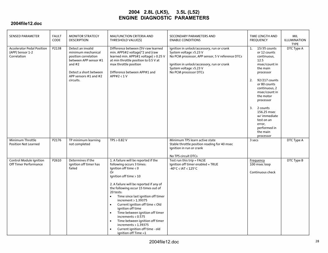
Accelerator Pedal Position (APP) Sensor 1-2 Correlation
P2138 Detect an invalid minimum mechanical position correlation between APP sensor #1 and #2 Detect a short between APP sensors #1 and #2 circuits.
Difference between (5V-raw learned min. APPS#2 voltage)*2 and (raw learned min. APPS#1 voltage) > 0.25 V at min throttle position to 0.5 V at max throttle position Difference between APP#1 and APP#2 < 1 V
Ignition in unlock/accessory, run or crank System voltage >5.23 V No PCM processor, APP sensor, 5 V reference DTCs Ignition in unlock/accessory, run or crank System voltage >5.23 V No PCM processor DTCs
1. 15/35 counts or 12 counts continuous, 12.5 msec/count in the main processor
2. 92/217 counts
or 80 counts continuous, 2 msec/count in the motor processor
3. 2 counts
156.25 msec w/ immediate test on an error, performed in the main processor
DTC Type A
Minimum Throttle Position Not Learned
P2176 TP minimum learning not completed
TPS > 0.82 V Minimum TPS learn active state Stable throttle position reading for 40 msec Ignition in run or crank No TPS circuit DTCs
3 secs DTC Type A
Control Module Ignition Off Timer Performance
P2610 Determines if the ignition off timer has failed
1. A failure will be reported if the following occurs 3 times: Ignition off time < 0 Or Ignition off time > 10 2. A failure will be reported if any of the following occur 15 times out of 20 tests: • Time since last ignition off timer
increment > 1.39375 • Current ignition off time < Old
ignition off time • Time between ignition off timer
increments < 0.575 • Time between ignition off timer
increments > 1.39375 • Current ignition off time - old
ignition off Time =1
Test run this trip = FALSE Ignition off timer enabled = TRUE -40°C < IAT < 125°C
Frequency 100 msec loop Continuous check
DTC Type B
2004file12.doc 28

2004 2.8L (LK5), 3.5L (L52) ENGINE DIAGNOSTIC PARAMETERS
2004file12.doc
2004file12.doc 29