Embed Size (px)
DESCRIPTION
2003 Nissan Altima 2.5 Serivce Manual
Citation preview
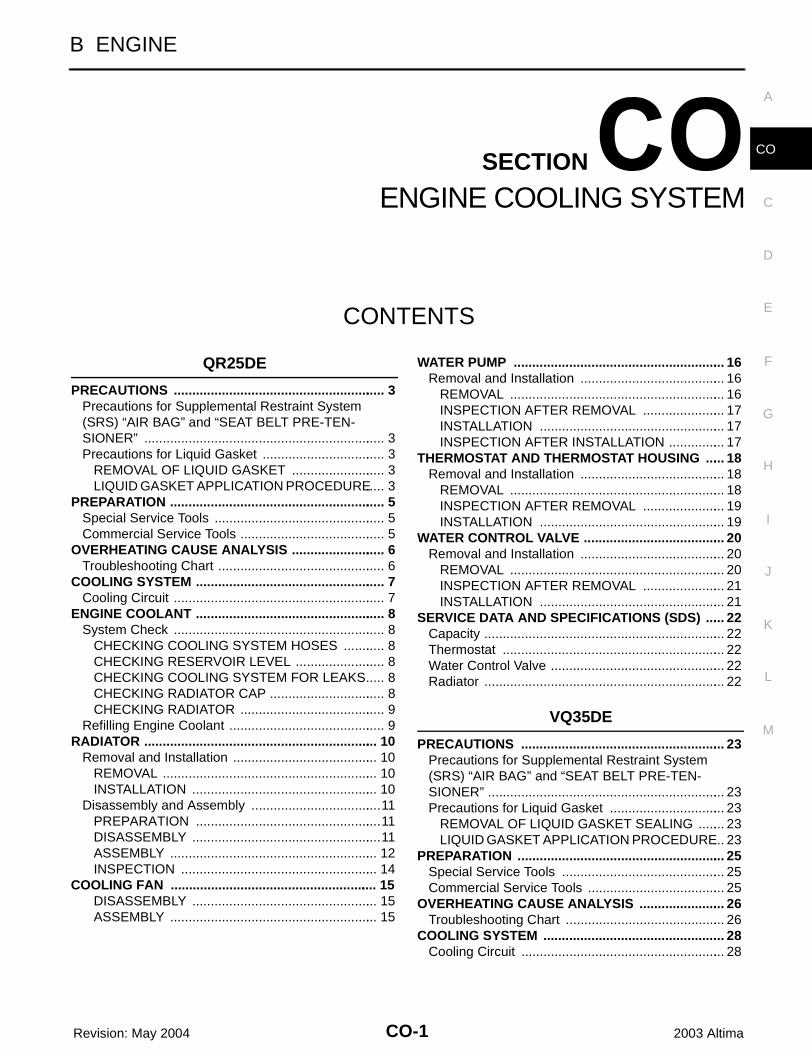
CO-1
ENGINE COOLING SYSTEM
B ENGINE
CONTENTS
C
D
E
F
G
H
I
J
K
L
M
SECTION
A
CO
Revision: May 2004 2003 Altima
QR25DE
PRECAUTIONS .......................................................... 3Precautions for Supplemental Restraint System (SRS) “AIR BAG” and “SEAT BELT PRE-TEN-SIONER” .................................................................. 3Precautions for Liquid Gasket .................................. 3
REMOVAL OF LIQUID GASKET .......................... 3LIQUID GASKET APPLICATION PROCEDURE ..... 3
PREPARATION ........................................................... 5Special Service Tools ............................................... 5Commercial Service Tools ........................................ 5
OVERHEATING CAUSE ANALYSIS .......................... 6Troubleshooting Chart .............................................. 6
COOLING SYSTEM .................................................... 7Cooling Circuit .......................................................... 7
ENGINE COOLANT .................................................... 8System Check .......................................................... 8
CHECKING COOLING SYSTEM HOSES ............ 8CHECKING RESERVOIR LEVEL ......................... 8CHECKING COOLING SYSTEM FOR LEAKS ..... 8CHECKING RADIATOR CAP ................................ 8CHECKING RADIATOR ........................................ 9
Refilling Engine Coolant ........................................... 9RADIATOR ................................................................ 10
Removal and Installation ........................................ 10REMOVAL ........................................................... 10INSTALLATION ................................................... 10
Disassembly and Assembly ....................................11PREPARATION ...................................................11DISASSEMBLY ....................................................11ASSEMBLY ......................................................... 12INSPECTION ...................................................... 14
COOLING FAN ......................................................... 15DISASSEMBLY ................................................... 15ASSEMBLY ......................................................... 15
WATER PUMP .......................................................... 16Removal and Installation ........................................ 16
REMOVAL ........................................................... 16INSPECTION AFTER REMOVAL ....................... 17INSTALLATION ................................................... 17INSPECTION AFTER INSTALLATION ................ 17
THERMOSTAT AND THERMOSTAT HOUSING ...... 18Removal and Installation ........................................ 18
REMOVAL ........................................................... 18INSPECTION AFTER REMOVAL ....................... 19INSTALLATION ................................................... 19
WATER CONTROL VALVE ....................................... 20Removal and Installation ........................................ 20
REMOVAL ........................................................... 20INSPECTION AFTER REMOVAL ....................... 21INSTALLATION ................................................... 21
SERVICE DATA AND SPECIFICATIONS (SDS) ...... 22Capacity .................................................................. 22Thermostat ............................................................. 22Water Control Valve ................................................ 22Radiator .................................................................. 22
VQ35DE
PRECAUTIONS ........................................................ 23Precautions for Supplemental Restraint System (SRS) “AIR BAG” and “SEAT BELT PRE-TEN-SIONER” ................................................................. 23Precautions for Liquid Gasket ................................ 23
REMOVAL OF LIQUID GASKET SEALING ........ 23LIQUID GASKET APPLICATION PROCEDURE ... 23
PREPARATION ......................................................... 25Special Service Tools ............................................. 25Commercial Service Tools ...................................... 25
OVERHEATING CAUSE ANALYSIS ........................ 26Troubleshooting Chart ............................................ 26
COOLING SYSTEM .................................................. 28Cooling Circuit ........................................................ 28

CO-2 Revision: May 2004 2003 Altima
ENGINE COOLANT .................................................. 29System Check ........................................................ 29
CHECKING COOLING SYSTEM HOSES ........... 29CHECKING RESERVOIR LEVEL ....................... 29CHECKING COOLING SYSTEM FOR LEAKS ... 29CHECKING RADIATOR CAP .............................. 29CHECKING RADIATOR ...................................... 30
RADIATOR ................................................................ 31Removal and Installation ........................................ 31
REMOVAL ........................................................... 31INSTALLATION .................................................... 31
Disassembly and Assembly .................................... 32PREPARATION ................................................... 32DISASSEMBLY ................................................... 32ASSEMBLY ......................................................... 33INSPECTION ....................................................... 35
COOLING FAN ......................................................... 36DISASSEMBLY ................................................... 36ASSEMBLY ......................................................... 36
WATER PUMP ...........................................................37Removal and Installation .........................................37
REMOVAL ............................................................37INSPECTION AFTER REMOVAL ........................39INSTALLATION ....................................................39
THERMOSTAT AND THERMOSTAT HOUSING .......42Removal and Installation .........................................42
REMOVAL ............................................................42INSPECTION AFTER REMOVAL ........................42INSTALLATION ....................................................43
WATER OUTLET AND WATER PIPING ...................44Removal and Installation .........................................44
REMOVAL ............................................................44INSTALLATION ....................................................44
SERVICE DATA AND SPECIFICATIONS (SDS) ......45Capacity ..................................................................45Thermostat ..............................................................45Radiator ..................................................................45

PRECAUTIONS
CO-3
[QR25DE]
C
D
E
F
G
H
I
J
K
L
M
A
CO
Revision: May 2004 2003 Altima
PRECAUTIONS PFP:00001
Precautions for Supplemental Restraint System (SRS) “AIR BAG” and “SEAT BELT PRE-TENSIONER” EBS00EZ7
The Supplemental Restraint System such as “AIR BAG” and “SEAT BELT PRE-TENSIONER”, used alongwith a front seat belt, helps to reduce the risk or severity of injury to the driver and front passenger for certaintypes of collision. This system includes seat belt switch inputs and dual stage front air bag modules. The SRSsystem uses the seat belt switches to determine the front air bag deployment, and may only deploy one frontair bag, depending on the severity of a collision and whether the front occupants are belted or unbelted.Information necessary to service the system safely is included in the SRS and SB section of this Service Man-ual.WARNING:● To avoid rendering the SRS inoperative, which could increase the risk of personal injury or death
in the event of a collision which would result in air bag inflation, all maintenance must be per-formed by an authorized NISSAN/INFINITI dealer.
● Improper maintenance, including incorrect removal and installation of the SRS, can lead to per-sonal injury caused by unintentional activation of the system. For removal of Spiral Cable and AirBag Module, see the SRS section.
● Do not use electrical test equipment on any circuit related to the SRS unless instructed to in thisService Manual. SRS wiring harnesses can be identified by yellow and/or orange harness connec-tors.
Precautions for Liquid Gasket EBS00DWG
REMOVAL OF LIQUID GASKET● After removing the mounting bolts and nuts, separate the mating
surface using a seal cutter and remove the sealant. CAUTION:Be careful not to damage the mating surfaces.
● In areas where the cutter is difficult to use, use a plastic hammerto lightly tap the areas where the sealant is applied.CAUTION:If for some unavoidable reason a tool such as a flat-bladescrewdriver is used, be careful not to damage the matingsurfaces.
LIQUID GASKET APPLICATION PROCEDURE1. Using a scraper, remove the old sealant adhering to the mating
surfaces.● Remove the sealant completely from the groove of mating sur-
face, mounting bolts, and bolt holes.2. Thoroughly clean the sealant mating surface removing all of the
adhering moisture, grease and foreign material.3. Attach the sealant tube to the tube presser.
Use Genuine RTV Silicone Sealant or equivalent. Refer toGI-43, "RECOMMENDED CHEMICAL PRODUCTS ANDSEALANTS" .
PBIC0002E
PBIC0003E

CO-4 Revision: May 2004
[QR25DE]PRECAUTIONS
2003 Altima
4. Apply the sealant without breaks to the specified location withthe specified dimensions.
● If there is a groove for the sealant application, apply the sealantto the groove.
● As for the bolt holes, normally apply the sealant inside the holes.If specified, it should be applied outside the holes. Make sure toread the instructions in this manual.
● Within five minutes of sealant application, install the matingcomponent.
● If the sealant protrudes, wipe it off immediately.● Do not retighten the nuts and bolts after installation.● After 30 minutes or more have passed from the installation, fill
the engine with the proper oil and coolant. Refer to MA-12,"RECOMMENDED FLUIDS AND LUBRICANTS" .CAUTION:If there are instructions in this manual, observe them.
EMA0622D
SEM159F

PREPARATION
CO-5
[QR25DE]
C
D
E
F
G
H
I
J
K
L
M
A
CO
Revision: May 2004 2003 Altima
PREPARATION PFP:00002
Special Service Tools EBS00DWH
The actual shape of the Kent-Moore tools may differ from those tools illustrated here.
Commercial Service Tools EBS00DWI
Tool number(Kent-Moore No.)Tool name
Description
WS39930000( -— )Tube presser
Pressing the tube of liquid gasket
EG17650301(J33984-A)Radiator cap tester adapter
Adapting radiator cap tester to radiator filler neck:a: 28 (1.10) dia.b: 31.4 (1.236) dia.c: 41.3 (1.626) dia.Unit: mm (in)
KV99103510( — )Radiator plate pliers A
Installing radiator upper and lower tanks
KV99103520( — )Radiator plate pliers B
Removing radiator upper and lower tanks
S-NT052
S-NT564
S-NT224
S-NT225
Tool name Description
Power tool Loosening bolts and nuts
PBIC0190E

CO-6 Revision: May 2004
[QR25DE]OVERHEATING CAUSE ANALYSIS
2003 Altima
OVERHEATING CAUSE ANALYSIS PFP:00012
Troubleshooting Chart EBS00DWJ
Symptom Check items
Cooling sys-tem parts malfunction
Poor heat transfer
Water pump malfunction Worn or loose drive belt
—
Thermostat stuck closed Coolant circulation
Damaged fins
Dust contamination or rock clogging
Mechanical damage
Clogged radiator cooling tube
Excess foreign material (rust, dirt, sand, etc.)
Reduced air flow
Cooling fan does not oper-ate
Engine cooling fans —High resistance to fan rota-tion
Damaged fan blades
Damaged radiator shroud — — —
Improper coolant mixture ratio
— — —
Poor coolant quality — Periodic maintenance —
Insufficient coolant
Coolant leaks
Cooling hoseLoose clamp
Cracked hose
Water pump Poor sealing
Radiator capLoose
Poor sealing
Radiator
O-ring for damage, deterio-ration or improper fitting
Cracked radiator tank
Cracked radiator core
Reservoir tank Cracked reservoir tank
Overflowing reservoir tankExhaust gas leaks into cooling system
Cylinder head deterioration
Cylinder head gasket dete-rioration
Except cool-ing system parts mal-function
— Overload on engine
Abusive driving
High engine rpm under no load
Driving in low gear for extended time
Driving at extremely high speed
Powertrain system mal-function
—Installed improper size wheels and tires
Dragging brakes
Improper ignition timing
Blocked or restricted air flow
Blocked radiator grille Installed car brassiere
—Mud contamination or paper clogging
Blocked bumper
Blocked radiator
Blocked condenser
Installed large fog lamp
COOLING SYSTEM
CO-7
[QR25DE]
C
D
E
F
G
H
I
J
K
L
M
A
CO
Revision: May 2004 2003 Altima
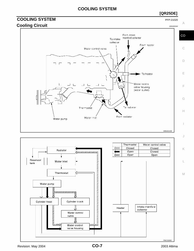
COOLING SYSTEM PFP:21020
Cooling Circuit EBS00DWK
WBIA0143E
PBIC0280E
CO-8 Revision: May 2004
[QR25DE]ENGINE COOLANT
2003 Altima
ENGINE COOLANT PFP:KQ100
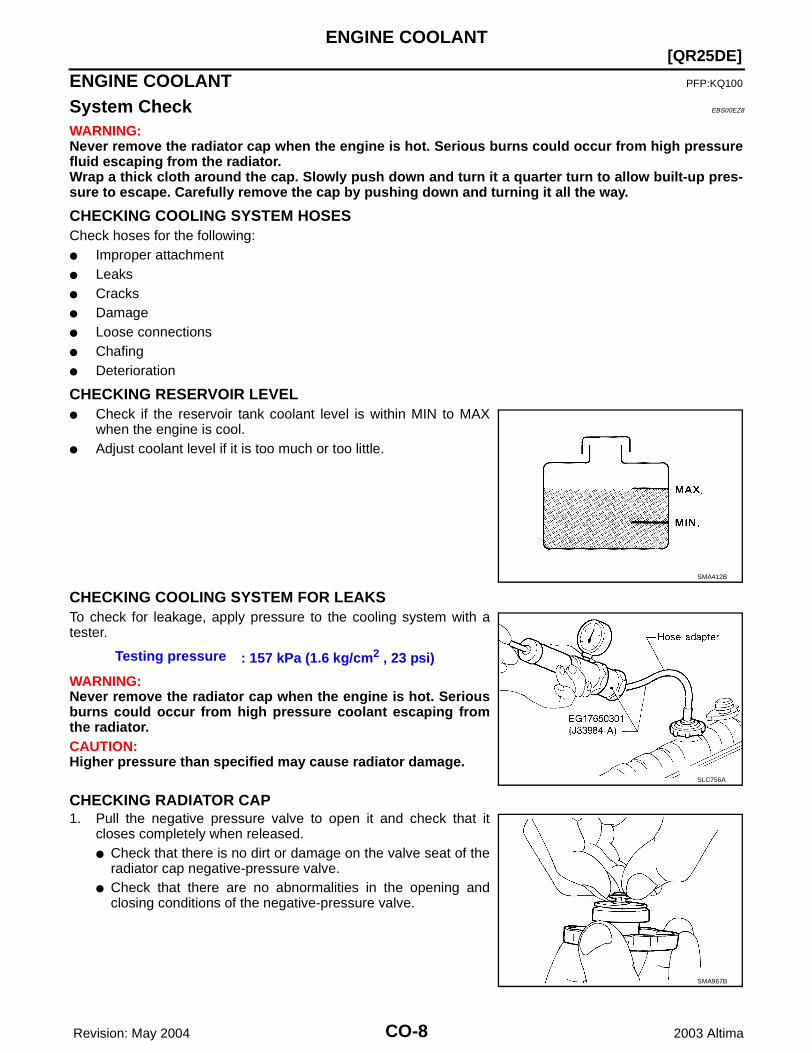
System Check EBS00EZ8
WARNING:Never remove the radiator cap when the engine is hot. Serious burns could occur from high pressurefluid escaping from the radiator.Wrap a thick cloth around the cap. Slowly push down and turn it a quarter turn to allow built-up pres-sure to escape. Carefully remove the cap by pushing down and turning it all the way.
CHECKING COOLING SYSTEM HOSESCheck hoses for the following:● Improper attachment● Leaks● Cracks● Damage● Loose connections● Chafing● Deterioration
CHECKING RESERVOIR LEVEL● Check if the reservoir tank coolant level is within MIN to MAX
when the engine is cool.● Adjust coolant level if it is too much or too little.
CHECKING COOLING SYSTEM FOR LEAKSTo check for leakage, apply pressure to the cooling system with atester.
WARNING:Never remove the radiator cap when the engine is hot. Seriousburns could occur from high pressure coolant escaping fromthe radiator.CAUTION:Higher pressure than specified may cause radiator damage.
CHECKING RADIATOR CAP1. Pull the negative pressure valve to open it and check that it
closes completely when released. ● Check that there is no dirt or damage on the valve seat of the
radiator cap negative-pressure valve.● Check that there are no abnormalities in the opening and
closing conditions of the negative-pressure valve.
SMA412B
Testing pressure : 157 kPa (1.6 kg/cm2 , 23 psi)
SLC756A
SMA967B

ENGINE COOLANT
CO-9
[QR25DE]
C
D
E
F
G
H
I
J
K
L
M
A
CO
Revision: May 2004 2003 Altima
2. Check radiator cap, apply pressure to cap using Tool.
● When connecting the radiator cap to the Tool, apply water orcoolant to the cap seal surface.
● Replace the cap if the there is an abnormality in the negative-pressure valve, or if the open-valve pressure is outside of thestandard values.
CHECKING RADIATORCheck radiator for mud or clogging. If necessary, clean radiator as follows.● Be careful not to bend or damage the radiator fins.● When radiator is cleaned without removal, remove all surrounding parts such as cooling fan, radiator
shroud and horns. Then tape the harness and connectors to prevent water from entering.1. Apply water by hose to the back side of the radiator core vertically downward.2. Apply water again to all radiator core surfaces once per minute.3. Stop washing when clear water flows off of the radiator.4. Blow air into the back side of radiator core vertically downward.
● Use compressed air lower than 490 kPa (5 kg/cm2 , 71 psi) and keep distance more than 300 mm (11.8in).
5. Blow air again into all the radiator core surfaces once per minute until no water sprays out.6. Check for leakage.
Refilling Engine Coolant EBS00EZ9
Changing the engine coolant is part of the required maintenance of the engine. Refer to MA-15, "ChangingEngine Coolant" .
Radiator cap relief pressureStandard : 78 - 98 kPa (0.8 - 1.0 kg/cm2 , 11 - 14 psi)Limit : 59 kPa (0.6 kg/cm2 , 14 psi)
SLC755A

CO-10Revision: May 2004
[QR25DE]RADIATOR
2003 Altima
RADIATOR PFP:21400
Removal and Installation EBS00T4I
WARNING:Never remove the radiator cap when the engine is hot. Serious burns could occur from high pressurecoolant escaping from the radiator. Wrap a thick cloth around the cap. Slowly turn it a quarter of a turnto release built-up pressure. Carefully remove radiator cap by turning it all the way.
REMOVAL1. Drain the coolant from the radiator. Refer to MA-15, “Changing Engine Coolant”.
CAUTION:Perform when engine is cold.
2. Remove fresh air duct. Refer to EM-16, “Removal and Installation”.3. Disconnect radiator upper and lower hoses.4. Remove the A/T fluid cooler hoses, if equipped.
● Plug hoses to avoid leakage of A/T fluid.5. Disconnect the reservoir tank hose.
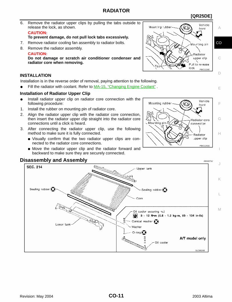
1. Radiator 2. Radiator upper clip 3. Mounting rubber
4. A/T fluid cooler hose (if equipped) 5. Radiator hose (lower) 6. Radiator fan assembly
7. Reservoir tank 8. Radiator hose (upper) 9. Radiator cap
10. Radiator core connection 11. Radiator drain plug
WBIA0282E
RADIATOR
CO-11
[QR25DE]
C
D
E
F
G
H
I
J
K
L
M
A
CO
Revision: May 2004 2003 Altima
6. Remove the radiator upper clips by pulling the tabs outside torelease the lock, as shown.CAUTION:To prevent damage, do not pull lock tabs excessively.
7. Remove radiator cooling fan assembly to radiator bolts.8. Remove the radiator assembly.
CAUTION:Do not damage or scratch air conditioner condenser andradiator core when removing.
INSTALLATIONInstallation is in the reverse order of removal, paying attention to the following.● Fill the radiator with coolant. Refer to MA-15, “Changing Engine Coolant” .
Installation of Radiator Upper Clip● Install radiator upper clip on radiator core connection with the
following procedure:1. Install the rubber on mounting pin of radiator core.2. Align the radiator upper clip with the radiator core connection,
then insert the radiator upper clip straight into the radiator coreconnections until a click is heard.
3. After connecting the radiator upper clip, use the followingmethod to make sure it is fully connected.● Visually confirm that the two radiator upper clips are con-
nected to the radiator core connections.● Move the radiator upper clip and the radiator forward and
backward to make sure they are securely connected.
Disassembly and Assembly EBS00T4J
PBIC1216E
PBIC1241E
SLC882AB
CO-12Revision: May 2004
[QR25DE]RADIATOR
2003 Altima
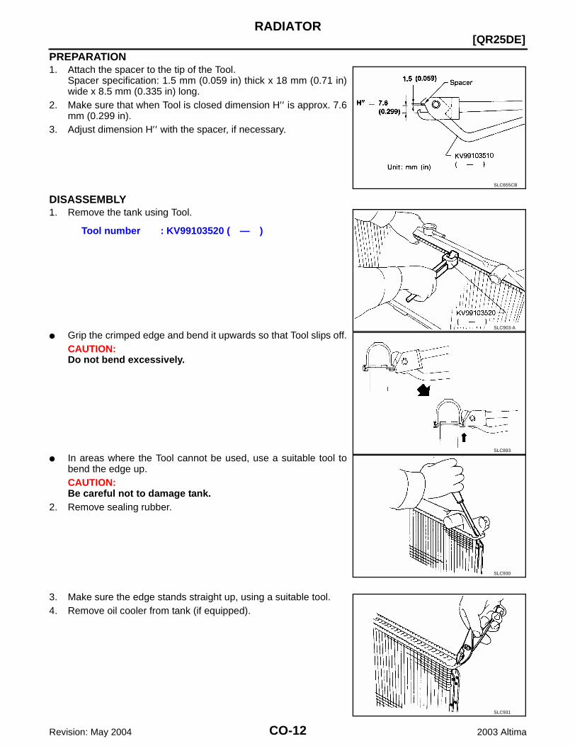
PREPARATION1. Attach the spacer to the tip of the Tool.
Spacer specification: 1.5 mm (0.059 in) thick x 18 mm (0.71 in)wide x 8.5 mm (0.335 in) long.
2. Make sure that when Tool is closed dimension H′′ is approx. 7.6mm (0.299 in).
3. Adjust dimension H′′ with the spacer, if necessary.
DISASSEMBLY1. Remove the tank using Tool.
● Grip the crimped edge and bend it upwards so that Tool slips off.CAUTION:Do not bend excessively.
● In areas where the Tool cannot be used, use a suitable tool tobend the edge up.CAUTION:Be careful not to damage tank.
2. Remove sealing rubber.
3. Make sure the edge stands straight up, using a suitable tool.4. Remove oil cooler from tank (if equipped).
SLC655CB
Tool number : KV99103520 ( — )
SLC903-A
SLC893
SLC930
SLC931

RADIATOR
CO-13
[QR25DE]
C
D
E
F
G
H
I
J
K
L
M
A
CO
Revision: May 2004 2003 Altima
ASSEMBLY1. Install the oil cooler (if equipped).
NOTE:Pay attention to direction of conical washer.
2. Clean the contact portion of the tank.
3. Install sealing rubber by pushing it in with your fingers.CAUTION:Be careful not to twist sealing rubber gasket.
4. Crimp tank in specified sequence using Tool.
SLC894
SLC932
SLC917A
Tool number : KV99103510 ( — )
SLC904-A
SLC896

CO-14Revision: May 2004
[QR25DE]RADIATOR
2003 Altima
● In the locations where Tool cannot be used use a suitabletool.
5. Make sure that the rim is completely crimped down.
6. Confirm that there is no leakage.Refer to CO-14, “INSPECTION”.
INSPECTION1. Apply pressure using Tool.
WARNING:To prevent the risk of the hose coming undone while underpressure, securely fasten it down with a hose clamp.CAUTION:Attach a hose to the oil cooler as well (if equipped).
2. Place radiator in water filled tank and check for leakage.
SLC897
Standard height “H” : 8.0 – 8.4 mm (0.315 – 0.331 in)
SLC554A
Tool number : EG17650301 (J-33984-A)
Specified pressure value : 157 kPa (1.6 kg/cm2 , 23 psi)
SLC933-A
SLC934
COOLING FAN
CO-15
[QR25DE]
C
D
E
F
G
H
I
J
K
L
M
A
CO
Revision: May 2004 2003 Altima
COOLING FAN PFP:21140
Removal and Installation EBS00T4K
WARNING:Never remove the radiator cap when the engine is hot. Serious burns could occur form high pressurecoolant escaping from the radiator
REMOVAL1. Drain engine coolant from radiator. Refer to MA-15, “Changing Engine Coolant“.
CAUTION:Perform when engine is cold.
2. Remove air cleaner duct assembly. Refer to EM-16, “Removal and Installation“.3. Disconnect radiator upper hose.4. Disconnect fan motor connectors.5. Remove radiator cooling fan assembly.
INSTALLATIONInstall in the reverse order of removal.● Cooling fan is controlled by ECM. For details, refer to EC-435, “DTC P1217 ENGINE OVER TEMPERA-
TURE”.
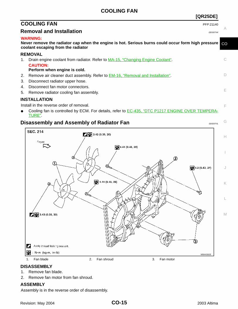
Disassembly and Assembly of Radiator Fan EBS00T4L
DISASSEMBLY1. Remove fan blade.2. Remove fan motor from fan shroud.
ASSEMBLYAssembly is in the reverse order of disassembly.
1. Fan blade 2. Fan shroud 3. Fan motor
WBIA0362E

CO-16 Revision: May 2004
[QR25DE]WATER PUMP
2003 Altima
WATER PUMP PFP:21020
Removal and Installation EBS00DWR
WARNING:Never remove the radiator cap when the engine is hot. Serious burns could occur from high pressurecoolant escaping from the radiator.
REMOVAL1. Drain coolant. Refer to MA-15, "Changing Engine Coolant" .
CAUTION:Perform when the engine is cold.
2. Remove the following parts:● Undercover, using power tools.● Alternator, water pump and air compressor drive belt.● Engine cover and coolant reservoir.● IPDM E/R (set aside). Refer to PG-24, "Removal and Installation of IPDM E/R" .● Front passenger side wheel and tire, and splash shield.● Engine ground.
3. Remove the water pump.NOTE:If necessary, the alternator and exhaust manifold catalytic convertor assembly must be removed toremove the water pipe.CAUTION:● Handle the water pump vane so that it does not contact any other parts. ● Water pump cannot be disassembled and should be replaced as an assembly.
KBIA0154E
1. Water pump 2. Gasket 3. Water pump housing
4. Water pipe

WATER PUMP
CO-17
[QR25DE]
C
D
E
F
G
H
I
J
K
L
M
A
CO
Revision: May 2004 2003 Altima
INSPECTION AFTER REMOVAL● Visually check that there is no significant dirt or rusting on the
water pump body and vane.● Check that there is no looseness in the vane shaft, and that it
turns smoothly when rotated by hand.● If the water pump does not perform properly, replace the water
pump assembly.
INSTALLATION● Installation is in the reverse order of removal.● When inserting water pipe end to cylinder block, apply a neutral detergent to O-ring. Then insert it imme-
diately.
INSPECTION AFTER INSTALLATION● After installing the water pump, check for leaks using the radiator cap tester. Refer to CO-14, "INSPEC-
TION" .
KBIA0155E
CO-18 Revision: May 2004
[QR25DE]THERMOSTAT AND THERMOSTAT HOUSING
2003 Altima
THERMOSTAT AND THERMOSTAT HOUSING PFP:21200
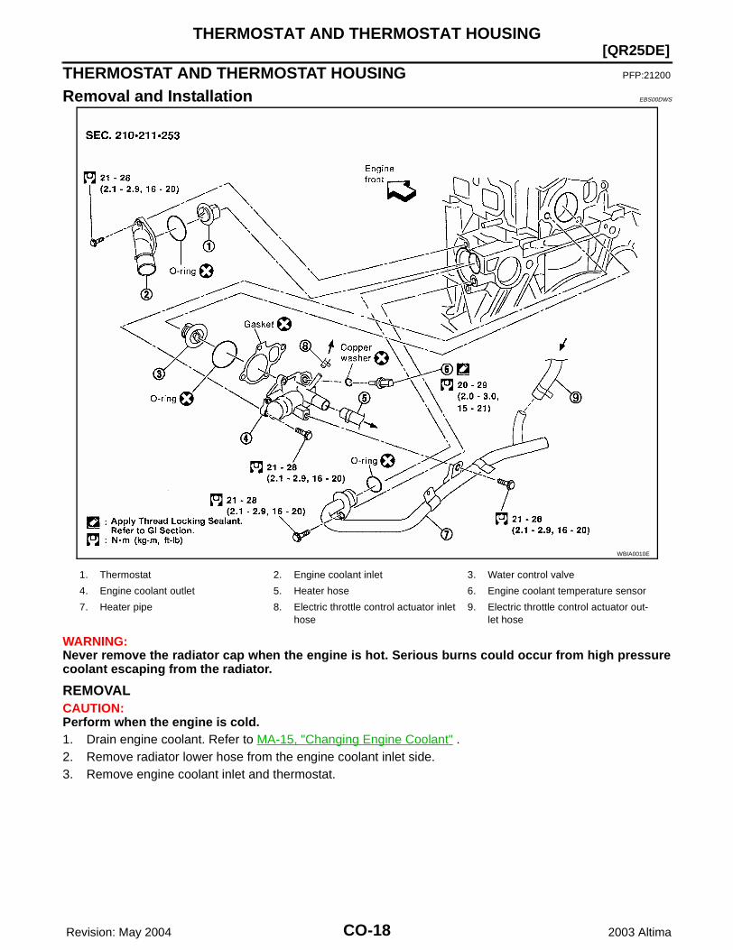
Removal and Installation EBS00DWS
WARNING:Never remove the radiator cap when the engine is hot. Serious burns could occur from high pressurecoolant escaping from the radiator.
REMOVALCAUTION:Perform when the engine is cold.1. Drain engine coolant. Refer to MA-15, "Changing Engine Coolant" .2. Remove radiator lower hose from the engine coolant inlet side.3. Remove engine coolant inlet and thermostat.
WBIA0010E
1. Thermostat 2. Engine coolant inlet 3. Water control valve
4. Engine coolant outlet 5. Heater hose 6. Engine coolant temperature sensor
7. Heater pipe 8. Electric throttle control actuator inlet hose
9. Electric throttle control actuator out-let hose
THERMOSTAT AND THERMOSTAT HOUSING
CO-19
[QR25DE]
C
D
E
F
G
H
I
J
K
L
M
A
CO
Revision: May 2004 2003 Altima
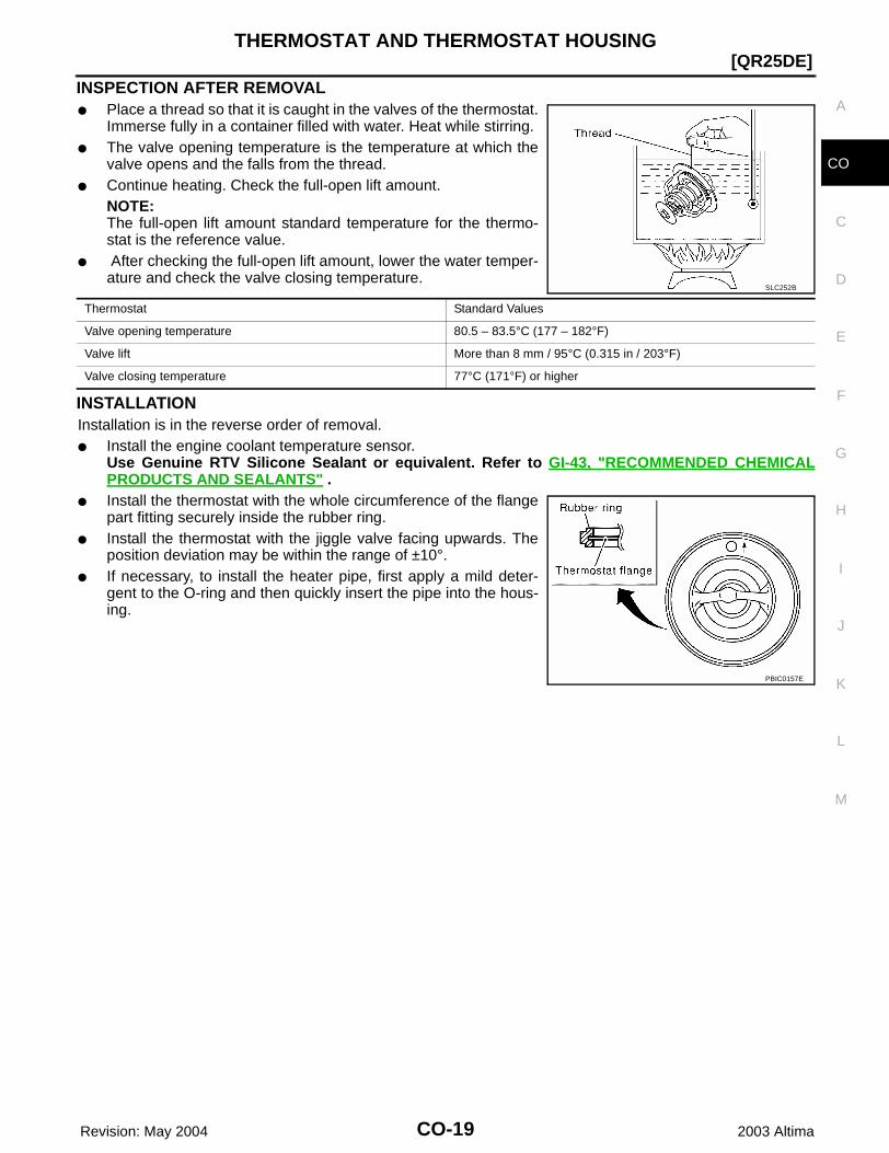
INSPECTION AFTER REMOVAL● Place a thread so that it is caught in the valves of the thermostat.
Immerse fully in a container filled with water. Heat while stirring. ● The valve opening temperature is the temperature at which the
valve opens and the falls from the thread.● Continue heating. Check the full-open lift amount.
NOTE:The full-open lift amount standard temperature for the thermo-stat is the reference value.
● After checking the full-open lift amount, lower the water temper-ature and check the valve closing temperature.
INSTALLATIONInstallation is in the reverse order of removal.● Install the engine coolant temperature sensor.
Use Genuine RTV Silicone Sealant or equivalent. Refer to GI-43, "RECOMMENDED CHEMICALPRODUCTS AND SEALANTS" .
● Install the thermostat with the whole circumference of the flangepart fitting securely inside the rubber ring.
● Install the thermostat with the jiggle valve facing upwards. Theposition deviation may be within the range of ±10°.
● If necessary, to install the heater pipe, first apply a mild deter-gent to the O-ring and then quickly insert the pipe into the hous-ing.
SLC252B
Thermostat Standard Values
Valve opening temperature 80.5 – 83.5°C (177 – 182°F)
Valve lift More than 8 mm / 95°C (0.315 in / 203°F)
Valve closing temperature 77°C (171°F) or higher
PBIC0157E

CO-20 Revision: May 2004
[QR25DE]WATER CONTROL VALVE
2003 Altima
WATER CONTROL VALVE PFP:21230
Removal and Installation EBS00DWT
WARNING:Never remove the radiator cap when the engine is hot. Serious burns could occur from high pressurecoolant escaping from the radiator.
REMOVALCAUTION:Perform when the engine cold.1. Drain the engine coolant. Refer to MA-15, "Changing Engine Coolant" .2. Remove the upper radiator hose, heater pipe, electric throttle control actuator inlet hose, and heater hose.3. Remove the engine coolant outlet.4. Remove the water control valve.
WBIA0010E
1. Thermostat 2. Engine coolant inlet 3. Water control valve
4. Engine coolant outlet 5. Heater hose 6. Engine coolant temperature sensor
7. Heater pipe 8. Electric throttle control actuator inlet hose
9. Electric throttle control actuator out-let hose
WATER CONTROL VALVE
CO-21
[QR25DE]
C
D
E
F
G
H
I
J
K
L
M
A
CO
Revision: May 2004 2003 Altima
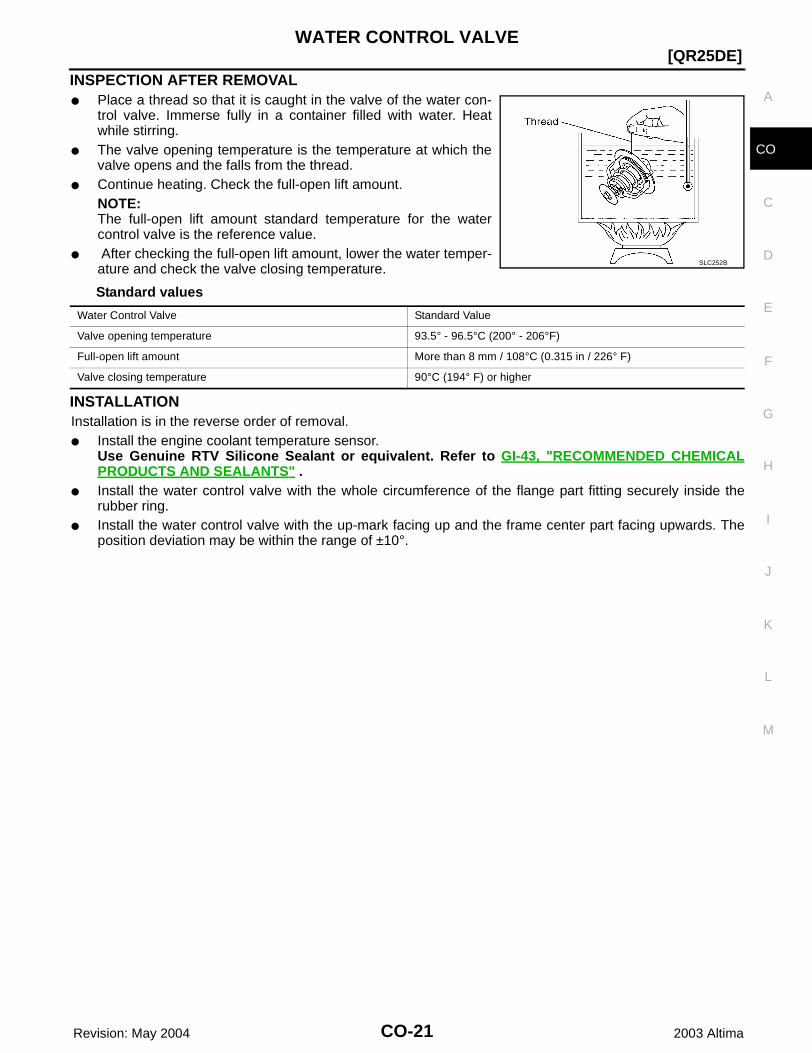
INSPECTION AFTER REMOVAL● Place a thread so that it is caught in the valve of the water con-
trol valve. Immerse fully in a container filled with water. Heatwhile stirring.
● The valve opening temperature is the temperature at which thevalve opens and the falls from the thread.
● Continue heating. Check the full-open lift amount.NOTE:The full-open lift amount standard temperature for the watercontrol valve is the reference value.
● After checking the full-open lift amount, lower the water temper-ature and check the valve closing temperature.
Standard values
INSTALLATIONInstallation is in the reverse order of removal.● Install the engine coolant temperature sensor.
Use Genuine RTV Silicone Sealant or equivalent. Refer to GI-43, "RECOMMENDED CHEMICALPRODUCTS AND SEALANTS" .
● Install the water control valve with the whole circumference of the flange part fitting securely inside therubber ring.
● Install the water control valve with the up-mark facing up and the frame center part facing upwards. Theposition deviation may be within the range of ±10°.
SLC252B
Water Control Valve Standard Value
Valve opening temperature 93.5° - 96.5°C (200° - 206°F)
Full-open lift amount More than 8 mm / 108°C (0.315 in / 226° F)
Valve closing temperature 90°C (194° F) or higher
CO-22 Revision: May 2004
[QR25DE]SERVICE DATA AND SPECIFICATIONS (SDS)
2003 Altima
SERVICE DATA AND SPECIFICATIONS (SDS) PFP:00030
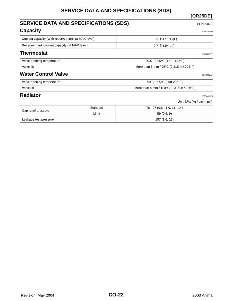
Capacity EBS00DWU
Thermostat EBS00DWV
Water Control Valve EBS00DWW
Radiator EBS00DWX
Unit: kPa (kg / cm2 , psi)
Coolant capacity (With reservoir tank at MAX level) 6.9 (7 1/4 qt.)
Reservoir tank coolant capacity (at MAX level) 0.7 (3/4 qt.)
Valve opening temperature 80.5 - 83.5°C (177 - 182°F)
Valve lift More than 8 mm / 95°C (0.315 in / 203°F)
Valve opening temperature 93.5-96.5°C (200-206°F)
Valve lift More than 8 mm / 108°C (0.315 in / 226°F)
Cap relief pressureStandard 78 - 98 (0.8 - 1.0, 11 - 14)
Limit 59 (0.6, 9)
Leakage test pressure 157 (1.6, 23)
PRECAUTIONS
CO-23
[VQ35DE]
C
D
E
F
G
H
I
J
K
L
M
A
CO
Revision: May 2004 2003 Altima
PRECAUTIONS PFP:00001
Precautions for Supplemental Restraint System (SRS) “AIR BAG” and “SEAT BELT PRE-TENSIONER” EBS00EZA
The Supplemental Restraint System such as “AIR BAG” and “SEAT BELT PRE-TENSIONER”, used alongwith a front seat belt, helps to reduce the risk or severity of injury to the driver and front passenger for certaintypes of collision. This system includes seat belt switch inputs and dual stage front air bag modules. The SRSsystem uses the seat belt switches to determine the front air bag deployment, and may only deploy one frontair bag, depending on the severity of a collision and whether the front occupants are belted or unbelted.Information necessary to service the system safely is included in the SRS and SB section of this Service Man-ual.WARNING:● To avoid rendering the SRS inoperative, which could increase the risk of personal injury or death
in the event of a collision which would result in air bag inflation, all maintenance must be per-formed by an authorized NISSAN/INFINITI dealer.
● Improper maintenance, including incorrect removal and installation of the SRS, can lead to per-sonal injury caused by unintentional activation of the system. For removal of Spiral Cable and AirBag Module, see the SRS section.
● Do not use electrical test equipment on any circuit related to the SRS unless instructed to in thisService Manual. SRS wiring harnesses can be identified by yellow and/or orange harness connec-tors.
Precautions for Liquid Gasket EBS00DWZ
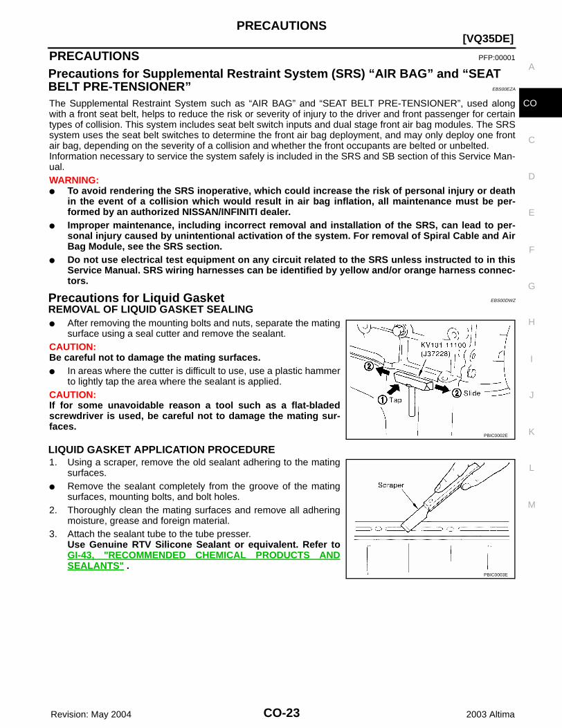
REMOVAL OF LIQUID GASKET SEALING● After removing the mounting bolts and nuts, separate the mating
surface using a seal cutter and remove the sealant. CAUTION:Be careful not to damage the mating surfaces.● In areas where the cutter is difficult to use, use a plastic hammer
to lightly tap the area where the sealant is applied.CAUTION:If for some unavoidable reason a tool such as a flat-bladedscrewdriver is used, be careful not to damage the mating sur-faces.
LIQUID GASKET APPLICATION PROCEDURE1. Using a scraper, remove the old sealant adhering to the mating
surfaces.● Remove the sealant completely from the groove of the mating
surfaces, mounting bolts, and bolt holes.2. Thoroughly clean the mating surfaces and remove all adhering
moisture, grease and foreign material.3. Attach the sealant tube to the tube presser.
Use Genuine RTV Silicone Sealant or equivalent. Refer toGI-43, "RECOMMENDED CHEMICAL PRODUCTS ANDSEALANTS" .
PBIC0002E
PBIC0003E

CO-24 Revision: May 2004
[VQ35DE]PRECAUTIONS
2003 Altima
4. Apply the sealant without breaks to the specified location withthe specified dimensions.
● If there is a groove for the sealant application, apply the sealantto the groove.
● As for the bolt holes, normally apply the sealant inside the holes.If specified in the procedure, it should also be applied outsidethe holes.
● Within five minutes of sealant application, install the matingcomponent.
● If the sealant protrudes, wipe it off immediately.● Do not retighten after the installation.● After 30 minutes or more have passed from the installation, fill
the engine with the specified oil and coolant. Refer to MA-12,"RECOMMENDED FLUIDS AND LUBRICANTS" .
EMA0622D
SEM159F

PREPARATION
CO-25
[VQ35DE]
C
D
E
F
G
H
I
J
K
L
M
A
CO
Revision: May 2004 2003 Altima
PREPARATION PFP:00002
Special Service Tools EBS00DX0
The actual shapes of Kent-Moore tools may from those of special service tools illustrated here.
Commercial Service Tools EBS00DX1
Tool number(Kent-Moore No.)Tool name
Description
WS39930000( – )Tube pressure
Pressing the tube of liquid gasket
EG17650301(J33984-A)Radiator cap tester adapter
Adapting radiator cap tester to radiator cap and radiator filler necka: 28 (1.10) dia.b: 31.4 (1.236) dia.c: 41.3 (1.626) dia.Unit: mm (in)
KV99103510( – )Radiator plate pliers A
Installing radiator upper and lower tanks
KV99103520( – )Radiator plate pliers B
Removing radiator upper and lower tanks
S-NT052
S-NT564
S-NT224
S-NT225
Tool name Description
Power tool Loosening bolts and nuts
PBIC0190E
CO-26 Revision: May 2004
[VQ35DE]OVERHEATING CAUSE ANALYSIS
2003 Altima
OVERHEATING CAUSE ANALYSIS PFP:00012
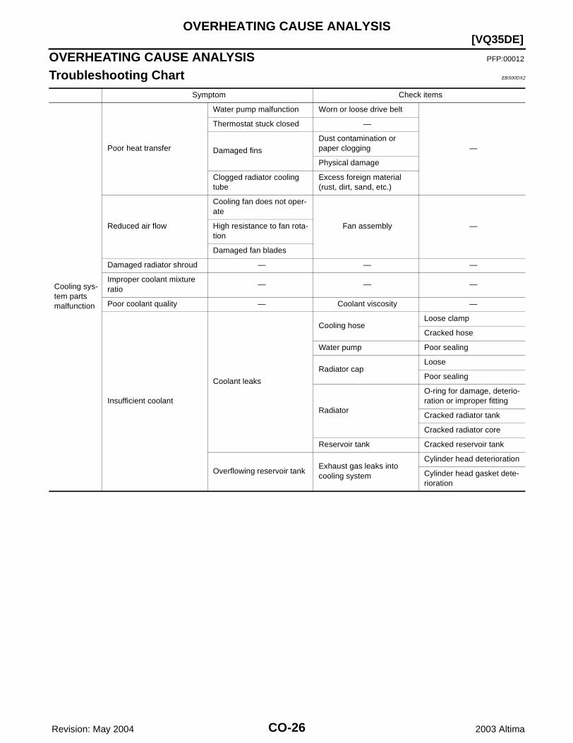
Troubleshooting Chart EBS00DX2
Symptom Check items
Cooling sys-tem parts malfunction
Poor heat transfer
Water pump malfunction Worn or loose drive belt
—
Thermostat stuck closed —
Damaged fins
Dust contamination or paper clogging
Physical damage
Clogged radiator cooling tube
Excess foreign material (rust, dirt, sand, etc.)
Reduced air flow
Cooling fan does not oper-ate
Fan assembly —High resistance to fan rota-tion
Damaged fan blades
Damaged radiator shroud — — —
Improper coolant mixture ratio
— — —
Poor coolant quality — Coolant viscosity —
Insufficient coolant
Coolant leaks
Cooling hoseLoose clamp
Cracked hose
Water pump Poor sealing
Radiator capLoose
Poor sealing
Radiator
O-ring for damage, deterio-ration or improper fitting
Cracked radiator tank
Cracked radiator core
Reservoir tank Cracked reservoir tank
Overflowing reservoir tankExhaust gas leaks into cooling system
Cylinder head deterioration
Cylinder head gasket dete-rioration
OVERHEATING CAUSE ANALYSIS
CO-27
[VQ35DE]
C
D
E
F
G
H
I
J
K
L
M
A
CO
Revision: May 2004 2003 Altima
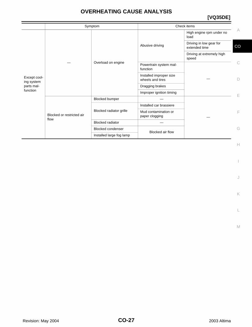
Except cool-ing system parts mal-function
— Overload on engine
Abusive driving
High engine rpm under no load
Driving in low gear for extended time
Driving at extremely high speed
Powertrain system mal-function
—Installed improper size wheels and tires
Dragging brakes
Improper ignition timing
Blocked or restricted air flow
Blocked bumper —
—
Blocked radiator grille
Installed car brassiere
Mud contamination or paper clogging
Blocked radiator —
Blocked condenserBlocked air flow
Installed large fog lamp
Symptom Check items
CO-28 Revision: May 2004
[VQ35DE]COOLING SYSTEM
2003 Altima
COOLING SYSTEM PFP:21020
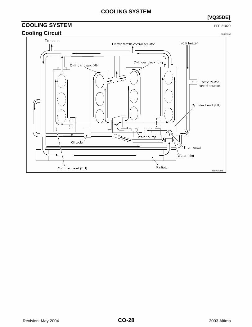
Cooling Circuit EBS00DX3
WBIA0144E

ENGINE COOLANT
CO-29
[VQ35DE]
C
D
E
F
G
H
I
J
K
L
M
A
CO
Revision: May 2004 2003 Altima
ENGINE COOLANT PFP:KQ100
System Check EBS00EZB
WARNING:Never remove the radiator cap when the engine is hot. Serious burns could occur from high pressurefluid escaping from the radiator.Wrap a thick cloth around the cap. Slowly push down and turn it a quarter turn to allow built-up pres-sure to escape. Carefully remove the cap by pushing down and turning it all the way.
CHECKING COOLING SYSTEM HOSESCheck hoses for the following:● Improper attachment● Leaks● Cracks● Damage● Loose connections● Chafing● Deterioration
CHECKING RESERVOIR LEVEL● Check if the reservoir tank coolant level is within MIN to MAX
when the engine is cool.● Adjust coolant level if it is too much or too little.
CHECKING COOLING SYSTEM FOR LEAKSTo check for leakage, apply pressure to the cooling system with atester.
WARNING:Never remove the radiator cap when the engine is hot. Seriousburns could occur from high pressure coolant escaping fromthe radiator.CAUTION:Higher pressure than specified may cause radiator damage.
CHECKING RADIATOR CAP1. Pull the negative pressure valve to open it and check that it
closes completely when released. ● Check that there is no dirt or damage on the valve seat of the
radiator cap negative-pressure valve.● Check that there are no abnormalities in the opening and
closing conditions of the negative-pressure valve.
SMA412B
Testing pressure : 157 kPa (1.6 kg/cm2 , 23 psi)
SLC756A
SMA967B
CO-30 Revision: May 2004
[VQ35DE]ENGINE COOLANT
2003 Altima
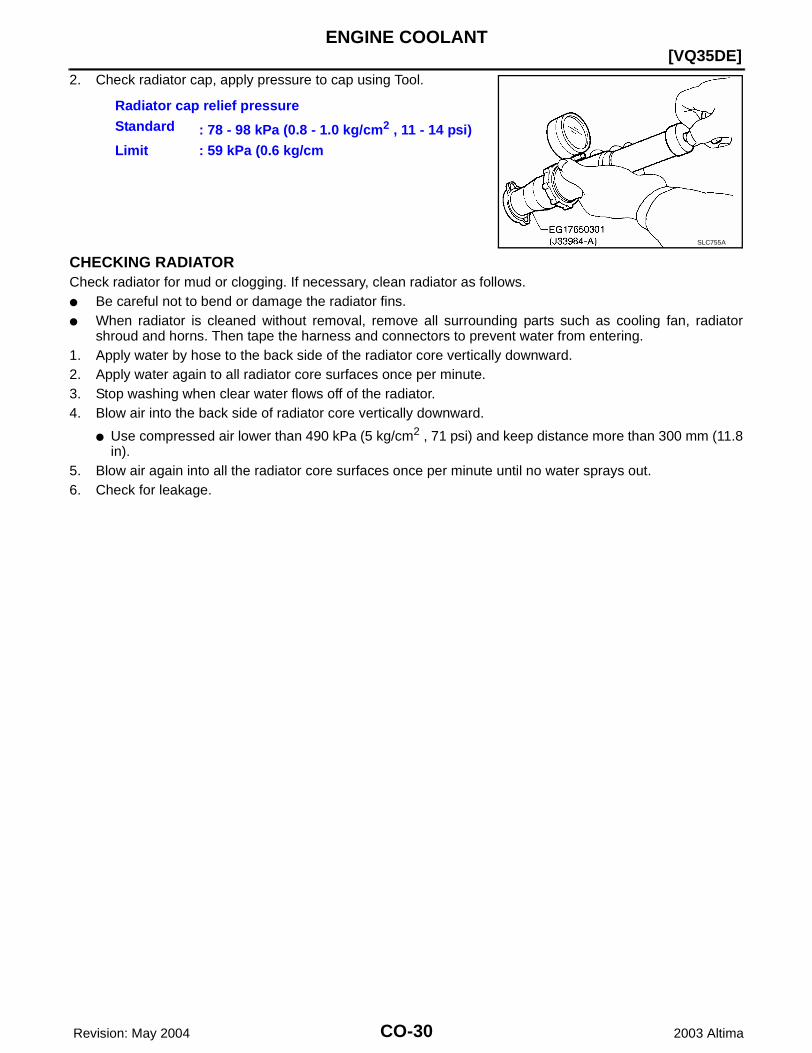
2. Check radiator cap, apply pressure to cap using Tool.
CHECKING RADIATORCheck radiator for mud or clogging. If necessary, clean radiator as follows.● Be careful not to bend or damage the radiator fins.● When radiator is cleaned without removal, remove all surrounding parts such as cooling fan, radiator
shroud and horns. Then tape the harness and connectors to prevent water from entering.1. Apply water by hose to the back side of the radiator core vertically downward.2. Apply water again to all radiator core surfaces once per minute.3. Stop washing when clear water flows off of the radiator.4. Blow air into the back side of radiator core vertically downward.
● Use compressed air lower than 490 kPa (5 kg/cm2 , 71 psi) and keep distance more than 300 mm (11.8in).
5. Blow air again into all the radiator core surfaces once per minute until no water sprays out.6. Check for leakage.
Radiator cap relief pressureStandard : 78 - 98 kPa (0.8 - 1.0 kg/cm2 , 11 - 14 psi)Limit : 59 kPa (0.6 kg/cm
SLC755A

RADIATOR
CO-31
[VQ35DE]
C
D
E
F
G
H
I
J
K
L
M
A
CO
Revision: May 2004 2003 Altima
RADIATOR PFP:21400
Removal and Installation EBS00T4Q
WARNING:Never remove the radiator cap when the engine is hot. Serious burns could occur from high pressurecoolant escaping from the radiator. Wrap a thick cloth around the cap. Slowly turn it a quarter of a turnto release built-up pressure. Carefully remove radiator cap by turning it all the way.
REMOVAL1. Drain the coolant from the radiator. Refer to MA-23, “Changing Engine Coolant”.
CAUTION:Perform when engine is cold.
2. Remove fresh air duct. Refer to EM-119, “Removal and Installation”.3. Disconnect radiator upper and lower hoses.4. Remove the A/T fluid cooler hoses, if equipped.
● Plug hoses to avoid leakage of A/T fluid.5. Disconnect the reservoir tank hose.
1. Radiator 2. Radiator upper clip 3. Mounting rubber
4. A/T fluid cooler hose (if equipped) 5. Radiator hose (lower) 6. Radiator fan assembly
7. Reservoir tank 8. Radiator hose (upper) 9. Radiator cap
10. Radiator core connection 11. Radiator drain plug
WBIA0282E

CO-32Revision: May 2004
[VQ35DE]RADIATOR
2003 Altima
6. Remove the radiator upper clips by pulling the tabs outside torelease the lock, as shown.CAUTION:To prevent damage, do not pull lock tabs excessively.
7. Remove radiator cooling fan assembly to radiator bolts.8. Remove the radiator assembly.
CAUTION:Do not damage or scratch air conditioner condenser andradiator core when removing.
INSTALLATIONInstallation is in the reverse order of removal, paying attention to the following.● Fill the radiator with coolant. Refer to MA-23, “Changing Engine Coolant”.
Installation of Radiator Upper Clip● Install radiator upper clip on radiator core connection with the
following procedure:1. Install the rubber on mounting pin of radiator core.2. Align the radiator upper clip with the radiator core connection,
then insert the radiator upper clip straight into the radiator coreconnections until a click is heard.
3. After connecting the radiator upper clip, use the followingmethod to make sure it is fully connected.● Visually confirm that the two radiator upper clips are con-
nected to the radiator core connections.● Move the radiator upper clip and the radiator forward and
backward to make sure they are securely connected.
Disassembly and Assembly EBS00T4R
PBIC1216E
PBIC1241E
SLC882AB
RADIATOR
CO-33
[VQ35DE]
C
D
E
F
G
H
I
J
K
L
M
A
CO
Revision: May 2004 2003 Altima
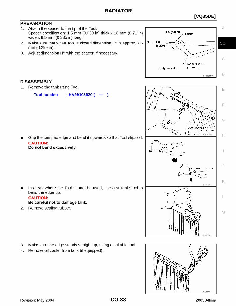
PREPARATION1. Attach the spacer to the tip of the Tool.
Spacer specification: 1.5 mm (0.059 in) thick x 18 mm (0.71 in)wide x 8.5 mm (0.335 in) long.
2. Make sure that when Tool is closed dimension H′′ is approx. 7.6mm (0.299 in).
3. Adjust dimension H′′ with the spacer, if necessary.
DISASSEMBLY1. Remove the tank using Tool.
● Grip the crimped edge and bend it upwards so that Tool slips off.CAUTION:Do not bend excessively.
● In areas where the Tool cannot be used, use a suitable tool tobend the edge up.CAUTION:Be careful not to damage tank.
2. Remove sealing rubber.
3. Make sure the edge stands straight up, using a suitable tool.4. Remove oil cooler from tank (if equipped).
SLC655CB
Tool number : KV99103520 ( — )
SLC903-A
SLC893
SLC930
SLC931

CO-34Revision: May 2004
[VQ35DE]RADIATOR
2003 Altima
ASSEMBLY1. Install the oil cooler (if equipped).
NOTE:Pay attention to direction of conical washer.
2. Clean the contact portion of the tank.
3. Install sealing rubber by pushing it in with your fingers.CAUTION:Be careful not to twist sealing rubber gasket.
4. Crimp tank in specified sequence using Tool.
SLC894
SLC932
SLC917A
Tool number : KV99103510 ( — )
SLC904-A
SLC896

RADIATOR
CO-35
[VQ35DE]
C
D
E
F
G
H
I
J
K
L
M
A
CO
Revision: May 2004 2003 Altima
● In the locations where Tool cannot be used use a suitabletool.
5. Make sure that the rim is completely crimped down.
6. Confirm that there is no leakage.Refer to CO-35, “INSPECTION”.
INSPECTION1. Apply pressure using Tool.
WARNING:To prevent the risk of the hose coming undone while underpressure, securely fasten it down with a hose clamp.CAUTION:Attach a hose to the oil cooler as well (if equipped).
2. Place radiator in water filled tank and check for leakage.
SLC897
Standard height “H” : 8.0 – 8.4 mm (0.315 – 0.331 in)
SLC554A
Tool number : EG17650301 (J-33984-A)
Specified pressure value : 157 kPa (1.6 kg/cm2 , 23 psi)
SLC933-A
SLC934
CO-36Revision: May 2004
[VQ35DE]COOLING FAN
2003 Altima
COOLING FAN PFP:21140
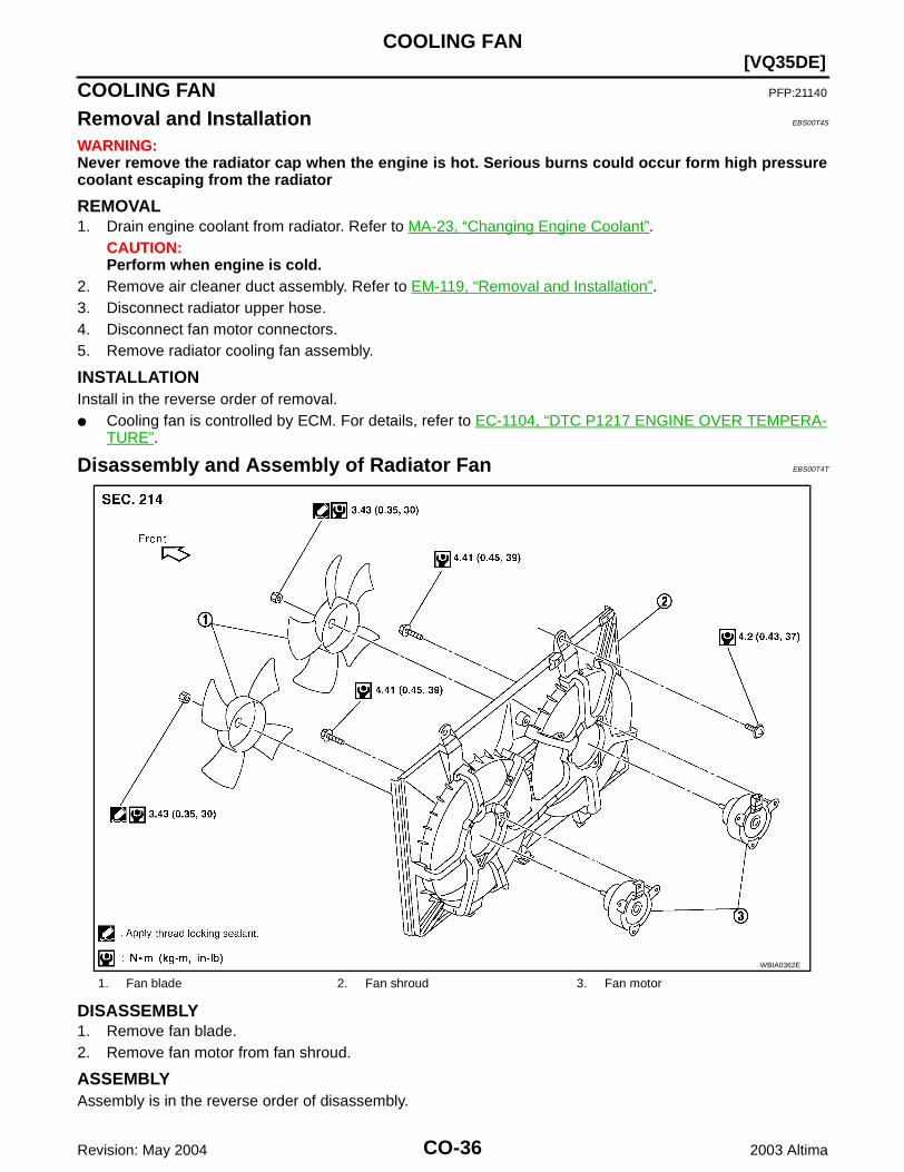
Removal and Installation EBS00T4S
WARNING:Never remove the radiator cap when the engine is hot. Serious burns could occur form high pressurecoolant escaping from the radiator
REMOVAL1. Drain engine coolant from radiator. Refer to MA-23, “Changing Engine Coolant”.
CAUTION:Perform when engine is cold.
2. Remove air cleaner duct assembly. Refer to EM-119, “Removal and Installation”.3. Disconnect radiator upper hose.4. Disconnect fan motor connectors.5. Remove radiator cooling fan assembly.
INSTALLATIONInstall in the reverse order of removal.● Cooling fan is controlled by ECM. For details, refer to EC-1104, “DTC P1217 ENGINE OVER TEMPERA-
TURE”.
Disassembly and Assembly of Radiator Fan EBS00T4T
DISASSEMBLY1. Remove fan blade.2. Remove fan motor from fan shroud.
ASSEMBLYAssembly is in the reverse order of disassembly.
1. Fan blade 2. Fan shroud 3. Fan motor
WBIA0362E
WATER PUMP
CO-37
[VQ35DE]
C
D
E
F
G
H
I
J
K
L
M
A
CO
Revision: May 2004 2003 Altima
WATER PUMP PFP:21020
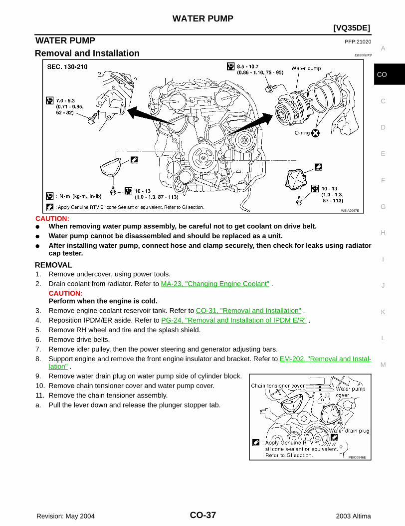
Removal and Installation EBS00DX9
CAUTION:● When removing water pump assembly, be careful not to get coolant on drive belt.● Water pump cannot be disassembled and should be replaced as a unit.● After installing water pump, connect hose and clamp securely, then check for leaks using radiator
cap tester.
REMOVAL1. Remove undercover, using power tools.2. Drain coolant from radiator. Refer to MA-23, "Changing Engine Coolant" .
CAUTION:Perform when the engine is cold.
3. Remove engine coolant reservoir tank. Refer to CO-31, "Removal and Installation" .4. Reposition IPDM/ER aside. Refer to PG-24, "Removal and Installation of IPDM E/R" .5. Remove RH wheel and tire and the splash shield.6. Remove drive belts. 7. Remove idler pulley, then the power steering and generator adjusting bars.8. Support engine and remove the front engine insulator and bracket. Refer to EM-202, "Removal and Instal-
lation" .9. Remove water drain plug on water pump side of cylinder block.10. Remove chain tensioner cover and water pump cover.11. Remove the chain tensioner assembly.a. Pull the lever down and release the plunger stopper tab.
WBIA0067E
PBIC0846E
CO-38 Revision: May 2004
[VQ35DE]WATER PUMP
2003 Altima
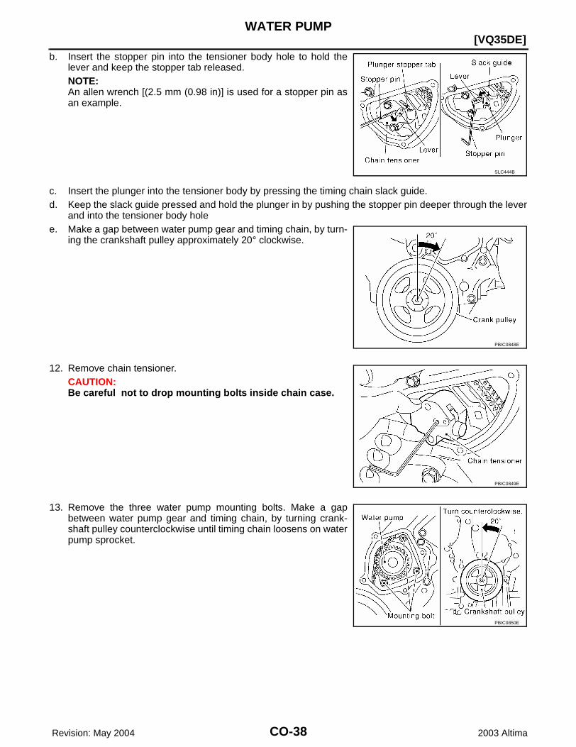
b. Insert the stopper pin into the tensioner body hole to hold thelever and keep the stopper tab released.NOTE:An allen wrench [(2.5 mm (0.98 in)] is used for a stopper pin asan example.
c. Insert the plunger into the tensioner body by pressing the timing chain slack guide.d. Keep the slack guide pressed and hold the plunger in by pushing the stopper pin deeper through the lever
and into the tensioner body holee. Make a gap between water pump gear and timing chain, by turn-
ing the crankshaft pulley approximately 20° clockwise.
12. Remove chain tensioner. CAUTION:Be careful not to drop mounting bolts inside chain case.
13. Remove the three water pump mounting bolts. Make a gapbetween water pump gear and timing chain, by turning crank-shaft pulley counterclockwise until timing chain loosens on waterpump sprocket.
SLC444B
PBIC0848E
PBIC0849E
PBIC0850E
WATER PUMP
CO-39
[VQ35DE]
C
D
E
F
G
H
I
J
K
L
M
A
CO
Revision: May 2004 2003 Altima
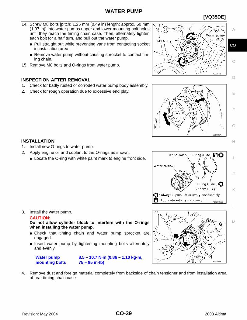
14. Screw M8 bolts [pitch: 1.25 mm (0.49 in) length: approx. 50 mm(1.97 in)] into water pumps upper and lower mounting bolt holesuntil they reach the timing chain case. Then, alternately tighteneach bolt for a half turn, and pull out the water pump.● Pull straight out while preventing vane from contacting socket
in installation area.● Remove water pump without causing sprocket to contact tim-
ing chain.15. Remove M8 bolts and O-rings from water pump.
INSPECTION AFTER REMOVAL1. Check for badly rusted or corroded water pump body assembly.2. Check for rough operation due to excessive end play.
INSTALLATION1. Install new O-rings to water pump.2. Apply engine oil and coolant to the O-rings as shown.
● Locate the O-ring with white paint mark to engine front side.
3. Install the water pump.CAUTION:Do not allow cylinder block to interfere with the O-ringswhen installing the water pump. ● Check that timing chain and water pump sprocket are
engaged.● Insert water pump by tightening mounting bolts alternately
and evenly.
4. Remove dust and foreign material completely from backside of chain tensioner and from installation areaof rear timing chain case.
JLC357B
SLC943A
PBIC0855E
Water pump mounting bolts
8.5 – 10.7 N·m (0.86 – 1.10 kg-m, 75 – 95 in-lb) SLC031B
CO-40 Revision: May 2004
[VQ35DE]WATER PUMP
2003 Altima
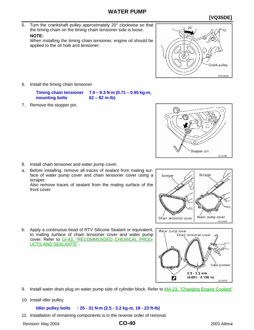
5. Turn the crankshaft pulley approximately 20° clockwise so thatthe timing chain on the timing chain tensioner side is loose.NOTE:When installing the timing chain tensioner, engine oil should beapplied to the oil hole and tensioner.
6. Install the timing chain tensioner.
7. Remove the stopper pin.
8. Install chain tensioner and water pump cover.a. Before installing, remove all traces of sealant from mating sur-
face of water pump cover and chain tensioner cover using ascraper.Also remove traces of sealant from the mating surface of thefront cover.
b. Apply a continuous bead of RTV Silicone Sealant or equivalent,to mating surface of chain tensioner cover and water pumpcover. Refer to GI-43, "RECOMMENDED CHEMICAL PROD-UCTS AND SEALANTS" .
9. Install water drain plug on water pump side of cylinder block. Refer to MA-23, "Changing Engine Coolant".
10. Install idler pulley.
11. Installation of remaining components is in the reverse order of removal.
PBIC0848E
Timing chain tensioner mounting bolts
7.0 – 9.3 N·m (0.71 – 0.95 kg-m, 62 – 82 in-lb)
SLC448B
SLC446B
SLC447B
Idler pulley bolts : 25 - 31 N·m (2.5 - 3.2 kg-m, 18 - 23 ft-lb)
WATER PUMP
CO-41
[VQ35DE]
C
D
E
F
G
H
I
J
K
L
M
A
CO
Revision: May 2004 2003 Altima
● Refill engine coolant. Refer to MA-23, "REFILLING ENGINE COOLANT" .● After starting engine, let idle for three minutes, then rev engine up to 3,000 rpm under no load to purge
air from the high-pressure chamber of the chain tensioner. The engine may produce a rattling noise.This indicates that air still remains in the chamber and is not a matter of concern.

CO-42 Revision: May 2004
[VQ35DE]THERMOSTAT AND THERMOSTAT HOUSING
2003 Altima
THERMOSTAT AND THERMOSTAT HOUSING PFP:21200
Removal and Installation EBS00DXA
REMOVAL1. Remove undercover using power tool.2. Drain coolant from radiator. Refer to MA-23, "Changing Engine Coolant" .
CAUTION:Perform when engine is cool.
3. Remove drive belts.4. Remove water drain plug on water pump side of the engine.5. Disconnect lower radiator hose.6. Remove engine coolant inlet and thermostat assembly.
● Do not disassemble engine coolant inlet and thermostat.Replace them as a unit, if necessary.
INSPECTION AFTER REMOVAL1. Check valve seating condition at ordinary room temperatures. It should seat tightly.2. Check valve opening temperature and maximum valve lift.
3. Then check if valve closes at 5°C (9°F) below valve openingtemperature.
WBIA0068E
SLC962AA
Thermostat Standard Values
Valve opening temperature 82°C (180°F)
Valve lift 8.6 mm / 95°C (0.339 in / 203°F)
SLC949A
THERMOSTAT AND THERMOSTAT HOUSING
CO-43
[VQ35DE]
C
D
E
F
G
H
I
J
K
L
M
A
CO
Revision: May 2004 2003 Altima
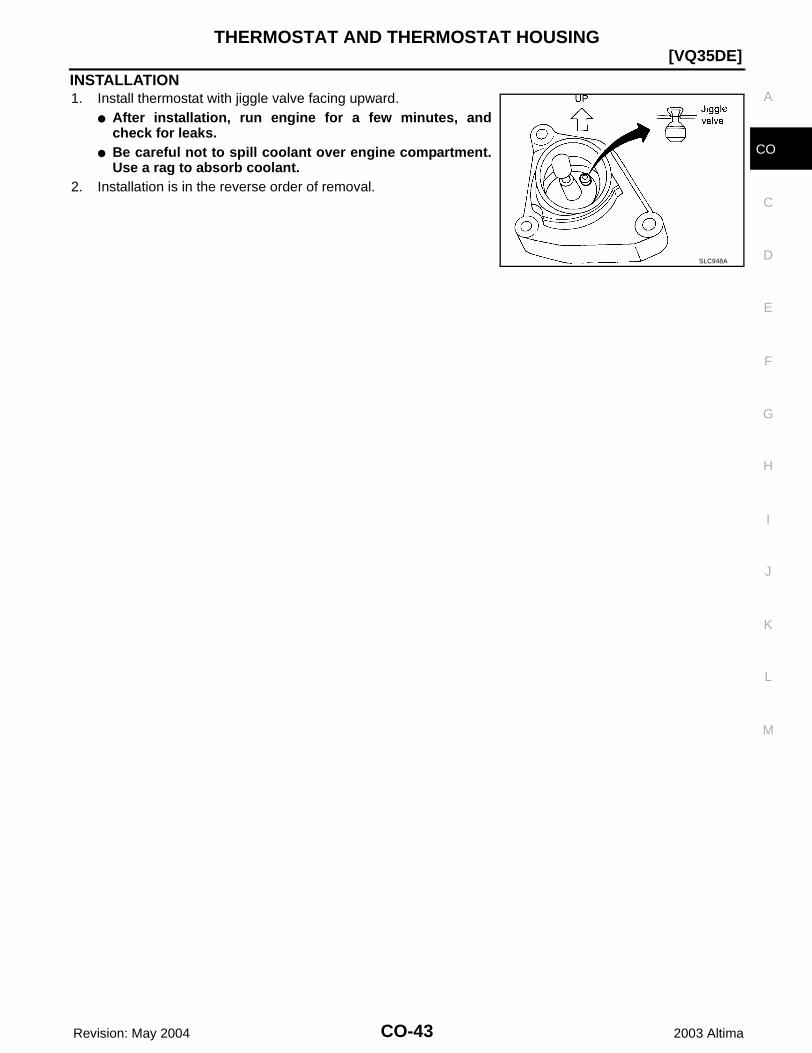
INSTALLATION1. Install thermostat with jiggle valve facing upward.
● After installation, run engine for a few minutes, andcheck for leaks.
● Be careful not to spill coolant over engine compartment.Use a rag to absorb coolant.
2. Installation is in the reverse order of removal.
SLC948A
CO-44 Revision: May 2004
[VQ35DE]WATER OUTLET AND WATER PIPING
2003 Altima
WATER OUTLET AND WATER PIPING PFP:11060
Removal and Installation EBS00GJI
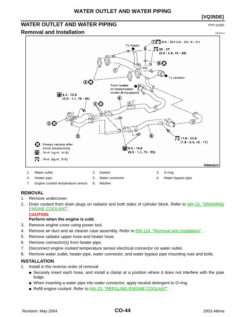
REMOVAL1. Remove undercover.2. Drain coolant from drain plugs on radiator and both sides of cylinder block. Refer to MA-23, "DRAINING
ENGINE COOLANT" .CAUTION:Perform when the engine is cold.
3. Remove engine cover using power tool. 4. Remove air duct and air cleaner case assembly. Refer to EM-119, "Removal and Installation" .5. Remove radiator upper hose and heater hose.6. Remove connector(s) from heater pipe.7. Disconnect engine coolant temperature sensor electrical connector on water outlet.8. Remove water outlet, heater pipe, water connector, and water bypass pipe mounting nuts and bolts.
INSTALLATION1. Install in the reverse order of removal.
● Securely insert each hose, and install a clamp at a position where it does not interfere with the pipebulge.
● When inserting a water pipe into water connector, apply neutral detergent to O-ring.● Refill engine coolant. Refer to MA-23, "REFILLING ENGINE COOLANT" .
WBIA0281E
1. Water outlet 2. Gasket 3. O-ring
4. Heater pipe 5. Water connector 6. Water bypass pipe
7. Engine coolant temperature sensor 8. Washer
SERVICE DATA AND SPECIFICATIONS (SDS)
CO-45
[VQ35DE]
C
D
E
F
G
H
I
J
K
L
M
A
CO
Revision: May 2004 2003 Altima
SERVICE DATA AND SPECIFICATIONS (SDS) PFP:00100
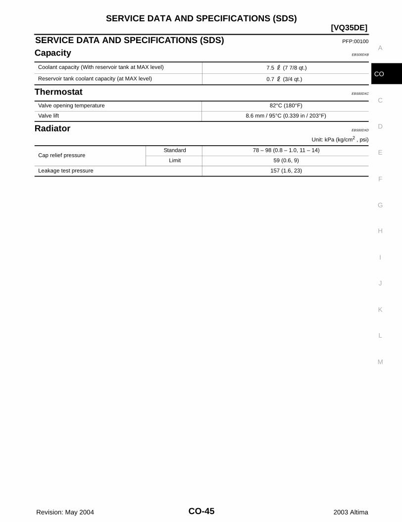
Capacity EBS00DXB
Thermostat EBS00DXC
Radiator EBS00DXD
Unit: kPa (kg/cm2 , psi)
Coolant capacity (With reservoir tank at MAX level) 7.5 (7 7/8 qt.)
Reservoir tank coolant capacity (at MAX level) 0.7 (3/4 qt.)
Valve opening temperature 82°C (180°F)
Valve lift 8.6 mm / 95°C (0.339 in / 203°F)
Cap relief pressureStandard 78 – 98 (0.8 – 1.0, 11 – 14)
Limit 59 (0.6, 9)
Leakage test pressure 157 (1.6, 23)

CO-46 Revision: May 2004
[VQ35DE]SERVICE DATA AND SPECIFICATIONS (SDS)
2003 Altima