Embed Size (px)
DESCRIPTION
2003 Nissan Altima 2.5 Serivce Manual
Citation preview

BCS-1
BODY CONTROL SYSTEM
K ELECTRICAL
CONTENTS
C
D
E
F
G
H
I
J
L
M
SECTION
A
B
BCS
Revision: May 2004 2003 Altima
PRECAUTIONS .......................................................... 2Precautions for Supplemental Restraint System (SRS) “AIR BAG” and “SEAT BELT PRE-TEN-SIONER” .................................................................. 2
BCM (BODY CONTROL MODULE) ........................... 3System Description .................................................. 3
BCM FUNCTION ................................................... 3COMBINATION SWITCH READING FUNCTION ..... 3CAN COMMUNICATION CONTROL .................... 5BCM STATUS CONTROL ..................................... 5SYSTEMS CONTROLLED BY BCM DIRECTLY ..... 6SYSTEMS CONTROLLED BY BCM AND IPDM E/R ........................................................................ 6MAJOR COMPONENTS AND CONTROL SYS-TEM ....................................................................... 6
CAN Communication System Description ................ 7FOR TCS MODELS .............................................. 7FOR A/T MODELS ................................................ 8FOR M/T MODELS ............................................. 10
Schematic ............................................................... 12CONSULT-II ............................................................ 14
CONSULT–II INSPECTION PROCEDURE ......... 14ITEMS OF EACH PART ...................................... 14
CAN Communication Inspection Using CONSULT-II (Self-Diagnosis) ................................................... 15Combination Switch Inspection According to Self-Diagnostic Results .................................................. 16Malfunctioning Operation of Lamps and Wipers ..... 19Inspection of BCM Power Supply and Ground Cir-cuit .......................................................................... 21

BCS-2
PRECAUTIONS
Revision: May 2004 2003 Altima
PRECAUTIONS PFP:00001
Precautions for Supplemental Restraint System (SRS) “AIR BAG” and “SEAT BELT PRE-TENSIONER” EKS00674
The Supplemental Restraint System such as “AIR BAG” and “SEAT BELT PRE-TENSIONER”, used alongwith a front seat belt, helps to reduce the risk or severity of injury to the driver and front passenger for certaintypes of collision. This system includes seat belt switch inputs and dual stage front air bag modules. The SRSsystem uses the seat belt switches to determine the front air bag deployment, and may only deploy one frontair bag, depending on the severity of a collision and whether the front occupants are belted or unbelted.Information necessary to service the system safely is included in the SRS and SB section of this Service Man-ual.WARNING:● To avoid rendering the SRS inoperative, which could increase the risk of personal injury or death
in the event of a collision which would result in air bag inflation, all maintenance must be per-formed by an authorized NISSAN/INFINITI dealer.
● Improper maintenance, including incorrect removal and installation of the SRS, can lead to per-sonal injury caused by unintentional activation of the system. For removal of Spiral Cable and AirBag Module, see the SRS section.
● Do not use electrical test equipment on any circuit related to the SRS unless instructed to in thisService Manual. SRS wiring harnesses can be identified by yellow and/or orange harnesses orharness connectors.

BCM (BODY CONTROL MODULE)
BCS-3
C
D
E
F
G
H
I
J
L
M
A
B
BCS
Revision: May 2004 2003 Altima
BCM (BODY CONTROL MODULE) PFP:284B2
System Description EKS003HE
● BCM (Body Control Module) controls the operation of various electrical units installed on the vehicle.
BCM FUNCTIONBCM has a combination switch reading function for reading the operation of combination switches (light, wiperwasher, turn signal) in addition to the function for controlling the operation of various electrical components.Also, it functions as an interface that receives signals from the A/C control unit (with manual A/C), A/C autoamplifier (with auto A/C), and sends signals to ECM using CAN communication.
COMBINATION SWITCH READING FUNCTION1. Description
● BCM reads combination switch (light, wiper washer, turn signal) status, and controls various electricalcomponents according to the results.
● BCM reads information of 20 switches and 5 diagnostic results by combining five output terminals(OUTPUT 1 - 5) and five input terminals (INPUT 1 - 5).
2. Operation description● BCM outputs battery voltage from input terminals (INPUT 1 - 5) all the time. At the same time output ter-
minals (OUTPUT 1 - 5) activate transistors in turn, and allow current to flow. At this time, if any (1 ormore) of the switches are ON, the input terminals corresponding to these switches detect current flow,and BCM judges switches are ON.
3. Example (When fog lamp switch is turned ON)● When fog lamp switch is turned ON, contact in combination switch turns ON. At this time if OUTPUT 4
transistor is activated, BCM detects current flow in INPUT 5.● When OUTPUT 4 transistor is ON, BCM detects current flow in INPUT5, and judges fog lamp switch is
ON. Then BCM sends fog lamp ON signal to IPDM E/R using CAN communication.● When OUTPUT 4 transistor is activated again, BCM detects current flow in INPUT 5, and confirms fog
lamp switch is continuously ON.
LKIA0095E

BCS-4
BCM (BODY CONTROL MODULE)
Revision: May 2004 2003 Altima
NOTE:Each OUTPUT terminal transistor is activated at 10 ms interval. Therefore, after a switch is turned ON,the electrical loads are activated with a time delay. But this time delay is so short that it cannot be noticed.
4. BCM - Operation table of combination switches● BCM reads operation status of combination switches by the combination shown in the table.
NOTE:Headlamp has a dual system switch for safe operation.
5. Operation mode
LKIA0096E
LKIA0097E

BCM (BODY CONTROL MODULE)
BCS-5
C
D
E
F
G
H
I
J
L
M
A
B
BCS
Revision: May 2004 2003 Altima
● Combination switch reading function has operation modes shown below.a. Normal mode
● When BCM is not in sleep mode, each OUTPUT (1 - 5) terminal turns ON-OFF at 10 ms intervals.b. Sleep mode
● When BCM is in sleep mode, transistors of OUTPUT 1 and 2 stop the output, and BCM enters low-cur-rent-consumption mode. OUTPUTS (3 - 5) turn ON-OFF at 60 ms intervals, and receives lighting switchinput only.
CAN COMMUNICATION CONTROLCAN communication is capable of dealing with a lot of information through the two communication lines (CANL-line, CAN H-line) connecting control units in the system. Also each control unit functions to transmit andreceive data, and reads necessary information only.
BCM STATUS CONTROLBCM changes its status depending on the operation status in order to save power consumption.1. CAN communication status
● With ignition switch ON, CAN communicates with other control units normally.● Control by BCM is being operated properly.● When ignition switch is OFF, switching to sleep mode is possible.● Even when ignition switch is OFF, if CAN communication with IPDM E/R and combination meter is
active, CAN communication status is active.2. Sleep status
● This is the status to stop CAN communication when ignition switch is turned OFF.● It transmits sleep request signal to IPDM E/R and combination meter.● Two seconds after CAN communication with other control unit stops, it switches to CAN communication
inactive status.3. CAN communication inactive status
● With ignition switch OFF, CAN communication is not active.● With ignition switch OFF, control performed only by BCM is active.● Two seconds after CAN communication with other control unit stops, it switches to CAN communication
inactive status.
4. Sleep status● BCM is activated with low-current-consumption mode.● CAN communication is not active.
LKIA0098E
BCS-6
BCM (BODY CONTROL MODULE)
Revision: May 2004 2003 Altima
● When CAN communication operation is detected, it switches to CAN communication status.● When control performed only by BCM is required by switch, it shifts to CAN communication inactive
mode.● It changes combination switch reading function.
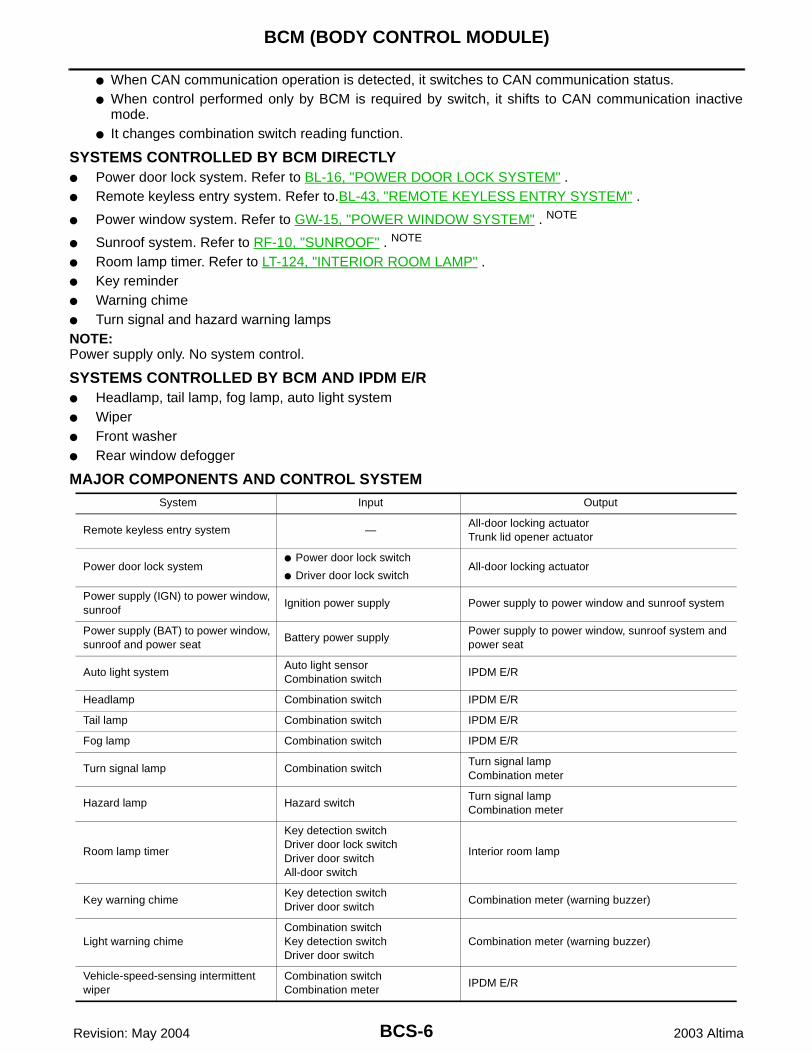
SYSTEMS CONTROLLED BY BCM DIRECTLY● Power door lock system. Refer to BL-16, "POWER DOOR LOCK SYSTEM" .● Remote keyless entry system. Refer to.BL-43, "REMOTE KEYLESS ENTRY SYSTEM" .
● Power window system. Refer to GW-15, "POWER WINDOW SYSTEM" . NOTE
● Sunroof system. Refer to RF-10, "SUNROOF" . NOTE
● Room lamp timer. Refer to LT-124, "INTERIOR ROOM LAMP" .● Key reminder● Warning chime● Turn signal and hazard warning lampsNOTE:Power supply only. No system control.
SYSTEMS CONTROLLED BY BCM AND IPDM E/R● Headlamp, tail lamp, fog lamp, auto light system● Wiper● Front washer● Rear window defogger
MAJOR COMPONENTS AND CONTROL SYSTEMSystem Input Output
Remote keyless entry system —All-door locking actuatorTrunk lid opener actuator
Power door lock system● Power door lock switch
● Driver door lock switchAll-door locking actuator
Power supply (IGN) to power window, sunroof
Ignition power supply Power supply to power window and sunroof system
Power supply (BAT) to power window, sunroof and power seat
Battery power supplyPower supply to power window, sunroof system and power seat
Auto light systemAuto light sensorCombination switch
IPDM E/R
Headlamp Combination switch IPDM E/R
Tail lamp Combination switch IPDM E/R
Fog lamp Combination switch IPDM E/R
Turn signal lamp Combination switchTurn signal lampCombination meter
Hazard lamp Hazard switchTurn signal lampCombination meter
Room lamp timer
Key detection switchDriver door lock switchDriver door switchAll-door switch
Interior room lamp
Key warning chimeKey detection switchDriver door switch
Combination meter (warning buzzer)
Light warning chimeCombination switchKey detection switchDriver door switch
Combination meter (warning buzzer)
Vehicle-speed-sensing intermittent wiper
Combination switchCombination meter
IPDM E/R

BCM (BODY CONTROL MODULE)
BCS-7
C
D
E
F
G
H
I
J
L
M
A
B
BCS
Revision: May 2004 2003 Altima
CAN Communication System Description EKS003HF
CAN (Controller Area Network) is a serial communication line for real time application. It is an on-vehicle mul-tiplex communication line with high data communication speed and excellent error detection ability. Many elec-tronic control units are equipped onto a vehicle, and each control unit shares information and links with othercontrol units during operation (not independent). In CAN communication, control units are connected with 2communication lines (CAN H line, CAN L line) allowing a high rate of information transmission with less wiring.Each control unit transmits/receives data but selectively reads required data only.
FOR TCS MODELSSystem Diagram
Input/Output Signal ChartT: Transmit R: Receive
Front washer Combination switchFront washer motorIPDM E/R
Rear window defogger Rear defogger switch IPDM E/R
Air conditioner switch signalA/C auto amplifier (with auto A/C)A/C control unit (with manual A/C)
ECM
Blower fan switch signalA/C auto amplifier (with auto A/C)A/C control unit (with manual A/C)
ECM
System Input Output
LKIA0015E
Signals ECM TCMCOMBINA-
TION METER
BCMABS/TCS
control unitIPDM E/R
Engine speed signal T R R
Engine coolant temperature signal T R
Accelerator pedal position signal T
Fuel consumption monitor signal T R
A/T warning lamp signal T R
A/T position indicator signal R T R R(R range only) R
ABS operation signal R T
TCS operation signal R R T
Air conditioner switch signal R T
Air conditioner compressor signal R T
A/C compressor request signal T R
Cooling fan motor operation signal R T
Cooling fan speed request signal T R
Position lights request R T R
Position lights status R T
Low beam request T R
Low beam status R R T

BCS-8
BCM (BODY CONTROL MODULE)
Revision: May 2004 2003 Altima
FOR A/T MODELSSystem Diagram
Input/Output Signal ChartT: Transmit R: Receive
High beam request R T R
High beam status R R T
Front fog lights request T R
Front fog light status R T
OD cancel switch signal R T R
Brake switch signal R T
Vehicle speed signalR T
R T R
Oil pressure switch R T
Sleep request1 R T
Sleep request2 T R
N range switch signal R T
P range switch signal R T
Seat belt buckle switch signal T R
Door switch signal R T R
Tail lamp request R T R
Turn indicator signal R T
Buzzer output signal R T
Trunk switch signal R T
ASCD main switch signal T R
ASCD cruise signal T R
Wiper operation R T
Wiper stop position signal R T
Rear window defogger switch signal T R
Rear window defogger control sig-nal
R R T
Signals ECM TCMCOMBINA-
TION METER
BCMABS/TCS
control unitIPDM E/R
LKIA0017E
Signals ECM TCMCOMBINATION
METERBCM IPDM E/R
Engine speed signal T R
Engine coolant temperature signal T R
Accelerator pedal position signal T R

BCM (BODY CONTROL MODULE)
BCS-9
C
D
E
F
G
H
I
J
L
M
A
B
BCS
Revision: May 2004 2003 Altima
Fuel consumption monitor signal T R
A/T warning lamp signal T R
A/T position indicator signal R T R R(R range only)
Air conditioner switch signal R T
Air conditioner compressor signal R T
A/C compressor request signal T R
Blower fan switch signal R(QR25DE) T
Cooling fan motor operation signal R T
Cooling fan speed request signal T R
Position lights request R T R
Position lights status R T
Low beam request T R
Low beam status R R T
High beam request R T R
High beam status R R T
Front fog lights request T R
Front fog light status R T
OD cancel switch signal R T R
Brake switch signal R T
Vehicle speed signalR T
R T R
Oil pressure switch R T
Sleep request1 R T
Sleep request2 T R
N range switch signal R T
P range switch signal R T
Seat belt buckle switch signal T R
Door switch signal R T R
Tail lamp request R T R
Turn indicator signal R T
Buzzer output signal R T
Trunk switch signal R T
ASCD main switch signal T R
ASCD cruise signal T R
Wiper operation R T
Wiper stop position signal R T
Rear window defogger switch signal T R
Rear window defogger control signal R R T
Signals ECM TCMCOMBINATION
METERBCM IPDM E/R

BCS-10
BCM (BODY CONTROL MODULE)
Revision: May 2004 2003 Altima
FOR M/T MODELSSystem Diagram
Input/Output Signal ChartT: Transmit R: Receive
LKIA0018E
Signals ECMCOMBINATION
METERBCM IPDM E/R
Engine speed signal T
Engine coolant temperature signal T
Fuel consumption monitor signal T
Air conditioner switch signal R T
Air conditioner compressor signal R T
A/C compressor request signal T R
Blower fan switch signal R(QR25DE) T
Cooling fan motor operation signal R T
Cooling fan speed request signal T R
Position lights request R T R
Position lights status R T
Low beam request T R
Low beam status R R T
High beam request R T R
High beam status R R T
Front fog lights request T R
Front fog light status R T
Vehicle speed signal R T
Oil pressure switch R T
Sleep request1 R T
Sleep request2 T R
Seat belt buckle switch signal T R
Door switch signal R T R
Tail lamp request R T R
Turn indicator signal R T
Buzzer output signal R T
Trunk switch signal R T
ASCD main switch signal T R
ASCD cruise signal T R
Wiper operation R T
Wiper stop position signal R T

BCM (BODY CONTROL MODULE)
BCS-11
C
D
E
F
G
H
I
J
L
M
A
B
BCS
Revision: May 2004 2003 Altima
Rear window defogger switch signal T R
Rear window defogger control signal R R T
Signals ECMCOMBINATION
METERBCM IPDM E/R

BCS-12
BCM (BODY CONTROL MODULE)
Revision: May 2004 2003 Altima
Schematic EKS003HG
WKWA0505E

BCM (BODY CONTROL MODULE)
BCS-13
C
D
E
F
G
H
I
J
L
M
A
B
BCS
Revision: May 2004 2003 Altima
WKWA0203E

BCS-14
BCM (BODY CONTROL MODULE)
Revision: May 2004 2003 Altima
CONSULT-II EKS003HH
CONSULT-II can display each diagnostic item using the following diagnostic test modes: work support, self-diagnostic results, data monitor and active test through data reception and command transmission via theBCM communication line.
CONSULT–II INSPECTION PROCEDURE1. With ignition switch OFF, connect CONSULT-II to data link con-
nector and turn ON ignition switch.2. Touch “START”.
3. Touch “BCM” on “SELECT SYSTEM” screen.
4. Select item to be diagnosed on “SELECT TEST ITEM” screen.
ITEMS OF EACH PART
BCM diagnostic test item
Check item, diagnostic test mode
Content
Inspection by part
Work support Changes setting of each function.
Self-diag results BCM performs self-diagnosis of CAN communication and combination switch.
Data monitor Displays the input data of BCM in real time.
Active test Gives a drive signal to a load to check the operation.
BBIA0002E
LIIA0033E
LKIA0099E
System and item CONSULT-II display
Diagnostic test mode (Inspection by part)
WORK SUPPORT
SELF−DIAG RESULTS
DATA MONITORACTIVE TEST
Power door lock system Door lock × ×
Rear defogger Rear defogger × ×
Key reminder Key reminder × ×

BCM (BODY CONTROL MODULE)
BCS-15
C
D
E
F
G
H
I
J
L
M
A
B
BCS
Revision: May 2004 2003 Altima
NOTE:1. For vehicles with auto light only2. For vehicles without auto light, related items are displayed, but monitoring cannot be performed.
CAN Communication Inspection Using CONSULT-II (Self-Diagnosis) EKS003HI
1. SELF-DIAGNOSTIC RESULT CHECK
1. Connect to CONSULT–II, and select “BCM” on “SELECT SYSTEM” screen.2. Select “BCM control unit ” on “SELECT WORK ITEM”screen, and select “SELF-DIAG RESULTS”.3. Check display content in self-diagnostic results.
Contents displayedNo malfunction>>Inspection EndMalfunction in CAN communication system>>GO TO 2.
2. SYMPTOM CHECK
1. Select “CAN diagnosis support monitor” in data monitor.2. Select “START” and check display content.
>> After printing the monitor items, go to “CAN System”. Refer to LAN-3, "CAN COMMUNICATION" .
Light reminder Light reminder × ×
Room lamp timer Interior room lamp × × ×
Power supply (IGN) to power window and sunroof
RAP × ×
Remote keyless entry system Keyless entry × × ×
Headlamp Headlamp × NOTE 1 × NOTE 2
Combination switch Combination switch × NOTE 2
BCM BCM control unit × ×
Turn signal lampHazard lamp
Flasher × ×
Air conditioner switch signalBlower fan switch signal
Signal buffer ×
System and item CONSULT-II display
Diagnostic test mode (Inspection by part)
WORK SUPPORT
SELF−DIAG RESULTS
DATA MONITORACTIVE TEST
CONSULT-II display code Diagnosis item
U1000
CAN COMM
CAN CIRC 1
CAN CIRC 2
CAN CIRC 3
CAN CIRC 4
Diagnosis itemSelf-diagnostic result content
Normal Not normal (Example)
CAN COMM OK NG
CAN CIRC 1 OK UNKWN
CAN CIRC 2 OK UNKWN
CAN CIRC 3 OK UNKWN
CAN CIRC 4 OK UNKWN

BCS-16
BCM (BODY CONTROL MODULE)
Revision: May 2004 2003 Altima
Combination Switch Inspection According to Self-Diagnostic Results EKS003HJ
1. SELF-DIAGNOSTIC RESULT CHECK
1. Connect to CONSULT–II, and select “BCM” on “SELECTSYSTEM” screen.2. Select “BCM control unit ” on “SELECT WORK ITEM”screen, and select “SELF-DIAG RESULTS”.3. Check display content in self-diagnostic results.
Display contentNo malfunction>>Inspection EndMalfunction in diagnosis system>>GO TO 2.Malfunction in headlamp switch system>>Replace lamp switch.
CONSULT-II display code
Self-diagnostic result content
Malfunctioning switch system Detection conditions Possible causes
B2049OPEN DETECT 1
The following switch operation shown below cannot be input.
● Front wiper Hi
● Intermittent control 1
● Intermittent control 2
BCM terminal No. 48 (Input 1) does not change.(Open circuit in diagnosis 1 system line or open malfunc-tion in output 1 transistor.)
● Vehicle harness between BCM and combination switch
● Wiper switch
● BCM
B2050OPEN DETECT 2
The following switch operation shown below cannot be input.
● Front washer
● Intermittent control 3
BCM terminal No. 49 (Input 2) does not change.(Open circuit in diagnosis 2 system line or open malfunc-tion in output 2 transistor.)
● Vehicle harness between BCM and combination switch
● Wiper switch
● BCM
B2051OPEN DETECT 3
The following switch operation shown below cannot be input.
● Front wiper Lo
● Front wiper INT
● Auto light
BCM terminal No. 50 (Input 3) does not change.(Open circuit in diagnosis 3 system line or open malfunc-tion in output 3 transistor.)
● Vehicle harness between BCM and combination switch
● Wiper switch(Front wiper Lo, INT)
● Lighting switch(Auto light)
● BCM
B2052OPEN DETECT 4
The following switch operation shown below cannot be input.
● TURN LH
● PASSING
● Headlamp 2
● Front fog lamp
BCM terminal No. 51 (Input 4) does not change.(Open circuit in diagnosis 4 system line or open malfunc-tion in output 4 transistor.)
● Vehicle harness between BCM and combination switch
● Lighting switch
● BCM
B2053OPEN DETECT 5
The following switch operation shown below cannot be input.
● TURN RH
● Headlamp 1
● HI BEAM
● Lighting switch 1st position
BCM terminal No. 52 (Input 5) does not change.(Open circuit in diagnosis 5 system line or open malfunc-tion in output 5 transistor.)
● Vehicle harness between BCM and combination switch
● Lighting switch
● BCM
B2054HEADLAMP 1 SW NG
Headlamp 1 malfunctionHeadlamp 1 switch OFFHeadlamp 2 switch ON
Lighting switch
B2055HEADLAMP 2 SW NG
Headlamp 2 malfunctionHeadlamp 1 switch ONHeadlamp 2 switch OFF
Lighting switch

BCM (BODY CONTROL MODULE)
BCS-17
C
D
E
F
G
H
I
J
L
M
A
B
BCS
Revision: May 2004 2003 Altima
2. HARNESS INSPECTION
1. Disconnect BCM connector and combination switch connector.2. Check continuity between BCM harness connector of applicable malfunctioning system and combination
switch connector terminals.
● Refer to LT wiring diagram LT–H/LAMP–01, LT-13 .OK or NGOK >> GO TO 3.NG >> Check harness between BCM and combination switch for open or short circuit.
3. INSPECTION OF BCM INPUT TERMINAL VOLTAGE
Connect BCM connector, and check BCM input terminal voltage ofapplicable malfunctioning system.
● Refer to LT wiring diagram LT–H/LAMP–01, LT-13 .OK or NGOK >> GO TO 4.NG >> Replace BCM.
Self-diagnos-tic result content
Terminals
Continuity(+) (–)
Connector Terminal (wire color) ConnectorTerminal
(wire color)
OPEN DETECT
1
M19
Input 1 48 (G/W)
M28
1 (G/W)
Yes
Output 1 47 (R/W) 6 (R/W)
OPEN DETECT
2
Input 2 49 (G/B) 2 (G/B)
Output 2 40 (R/B) 7 (R/B)
OPEN DETECT
3
Input 3 50 (G/R) 3 (G/R)
Output 3 41 (R/G) 10 (R/G)
OPEN DETECT
4
Input 4 51 (G/Y) 4 (G/Y)
Output 4 42 (R/Y) 9 (R/Y)
OPEN DETECT
5
Input 5 52 (L/W) 5 (L/W)
Output 5 43 (L) 8 (L)
SKIA1154E
Self-diagnostic result content
Terminals
VoltageBCM
Connector Terminal (wire color)
OPEN DETECT 1
M19
Input 1 48 (G/W)
4.5V or more
OPEN DETECT 2 Input 2 49 (G/B)
OPEN DETECT 3 Input 3 50 (G/R)
OPEN DETECT 4 Input 4 51 (G/Y)
OPEN DETECT 5 Input 5 52 (L/W)
SKIA1155E
BCS-18
BCM (BODY CONTROL MODULE)
Revision: May 2004 2003 Altima
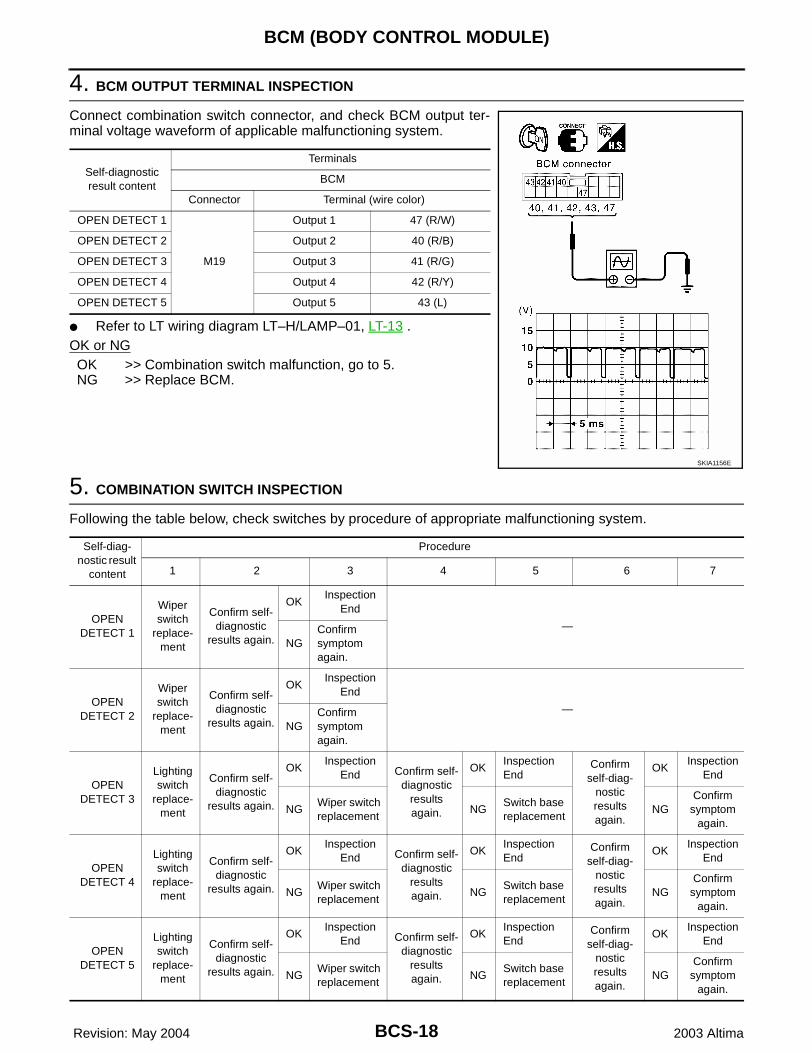
4. BCM OUTPUT TERMINAL INSPECTION
Connect combination switch connector, and check BCM output ter-minal voltage waveform of applicable malfunctioning system.
● Refer to LT wiring diagram LT–H/LAMP–01, LT-13 .OK or NGOK >> Combination switch malfunction, go to 5.NG >> Replace BCM.
5. COMBINATION SWITCH INSPECTION
Following the table below, check switches by procedure of appropriate malfunctioning system.
Self-diagnostic result content
Terminals
BCM
Connector Terminal (wire color)
OPEN DETECT 1
M19
Output 1 47 (R/W)
OPEN DETECT 2 Output 2 40 (R/B)
OPEN DETECT 3 Output 3 41 (R/G)
OPEN DETECT 4 Output 4 42 (R/Y)
OPEN DETECT 5 Output 5 43 (L)
SKIA1156E
Self-diag-nostic result
content
Procedure
1 2 3 4 5 6 7
OPEN DETECT 1
Wiper switch
replace-ment
Confirm self-diagnostic
results again.
OKInspection
End
—
NGConfirm symptom again.
OPEN DETECT 2
Wiper switch
replace-ment
Confirm self-diagnostic
results again.
OKInspection
End
—
NGConfirm symptom again.
OPEN DETECT 3
Lighting switch
replace-ment
Confirm self-diagnostic
results again.
OKInspection
End Confirm self-diagnostic
results again.
OKInspection End
Confirm self-diag-
nostic results again.
OKInspection
End
NGWiper switch replacement
NGSwitch base replacement
NGConfirm
symptom again.
OPEN DETECT 4
Lighting switch
replace-ment
Confirm self-diagnostic
results again.
OKInspection
End Confirm self-diagnostic
results again.
OKInspection End
Confirm self-diag-
nostic results again.
OKInspection
End
NGWiper switch replacement
NGSwitch base replacement
NGConfirm
symptom again.
OPEN DETECT 5
Lighting switch
replace-ment
Confirm self-diagnostic
results again.
OKInspection
End Confirm self-diagnostic
results again.
OKInspection End
Confirm self-diag-
nostic results again.
OKInspection
End
NGWiper switch replacement
NGSwitch base replacement
NGConfirm
symptom again.

BCM (BODY CONTROL MODULE)
BCS-19
C
D
E
F
G
H
I
J
L
M
A
B
BCS
Revision: May 2004 2003 Altima
>> Inspection End
Malfunctioning Operation of Lamps and Wipers EKS003HK
1. SYMPTOM CHECK
Confirm symptom, and confirm malfunctioning system No. from the table below.
>> GO TO 2.
Ignition switch
SymptomMalfunc-tioning system
Possible causes
ON● LH Turn signal lamp and RH Turn signal lamp on
● Front wiper on (LO speed)1
● Vehicle harness shorted between BCM input terminal No. 1 and BCM output terminal No. 1
● BCM
● Combination switchOFF —
ON● Headlamp on (HI and LO)
● Front wiper on (HI speed)2
● Vehicle harness shorted between BCM input terminal No. 2 and BCM output terminal No. 2
● BCM
● Combination switchOFF Headlamp on (HI and LO)
ON Headlamp on (HI and LO)
3
● Vehicle harness shorted between BCM input terminal No. 3 and BCM output terminal No. 3
● BCM
● Combination switchOFF Headlamp on (HI and LO)
ON● Parking lamp and Tail lamp on
● Headlamp on at certain degrees of brightness4
● Vehicle harness shorted between BCM input terminal No. 4 and BCM output terminal No. 4
● BCM
● Combination switchOFF Parking lamp and Tail lamp on
ON Front fog lamp on
5
● Vehicle harness shorted between BCM input terminal No. 5 and BCM output terminal No. 5
● BCM
● Combination switchOFF Front fog lamp on

BCS-20
BCM (BODY CONTROL MODULE)
Revision: May 2004 2003 Altima
2. HARNESS INSPECTION
1. Disconnect BCM connector and combination switch connector.2. Check continuity between BCM harness connector of applicable malfunctioning system and body ground.
● Refer to LT wiring diagram LT–H/LAMP–01, LT-13 .OK or NGOK >> GO TO 3.NG >> Check harness between BCM and combination switch for short circuit.
3. INSPECTION OF BCM INPUT TERMINAL VOLTAGE
Connect BCM connector. Check voltage between BCM input termi-nal of applicable malfunctioning system and body ground.
● Refer to LT wiring diagram LT–H/LAMP–01, LT-13 .OK or NGOK >> Combination switch malfunction, go to 4.NG >> Replace BCM.
Self-diagnostic result content
Terminals
Continuity(+)(–)
Connector Terminal (wire color)
OPEN DETECT 1
M19
Input 1 48 (G/W)
Ground No
Output 1 47 (R/W)
OPEN DETECT 2Input 2 49 (G/B)
Output 2 40 (R/B)
OPEN DETECT 3Input 3 50 (G/R)
Output 3 41 (R/G)
OPEN DETECT 4Input 4 51 (G/Y)
Output 4 42 (R/Y)
OPEN DETECT 5Input 5 52 (L/W)
Output 5 43 (L)
SKIA1157E
Self-diagnostic result content
Terminals
Voltage(+)(–)
Connector Terminal (wire color)
OPEN DETECT 1
M19
48 (G/W)
Ground 4.5V or more
OPEN DETECT 2 49 (G/B)
OPEN DETECT 3 50 (G/R)
OPEN DETECT 4 51 (G/Y)
OPEN DETECT 5 52 (L/W)
SKIA1155E

BCM (BODY CONTROL MODULE)
BCS-21
C
D
E
F
G
H
I
J
L
M
A
B
BCS
Revision: May 2004 2003 Altima
4. COMBINATION SWITCH INSPECTION
Following the table below, check combination switch.
>> Inspection End
Inspection of BCM Power Supply and Ground Circuit EKS003HL
1. FUSE AND FUSIBLE LINK INSPECTION
Check if any of the following BCM fuses and fusible links are blown.
● Refer to LT wiring diagram LT–H/LAMP–01, LT-13 .OK or NGOK >> GO TO 2.NG >> Replace fuse or fusible link.
2. POWER SUPPLY CIRCUIT INSPECTION
Disconnect BCM connector. To measure voltage, connect followingconnector terminals to positive probe and body ground to negativeone.
● Refer to LT wiring diagram LT–H/LAMP–01, LT-13 .OK or NGOK >> GO TO 3.NG >> Replace BCM power supply circuit harness.
Procedure
1 2 3 4 5 6 7
Lighting switch
replacement
Confirm self-diagnostic
results again.
OKInspection
End Confirm self-diagnostic
results again.
OKInspection
End Confirm self-diagnostic
results again.
OKInspection
End
NGWiper switch replacement
NGReplace-ment of
switch baseNG
Confirm symptom
again.
Terminal No. Signal name Fuse No., fusible link No.
7 Battery f
35 Ignition switch ON or START 12
36 Ignition switch ACC or ON 6
Terminals
Power sourceIgnition switch
Reference voltage (V)
(+)
(–)Connector
Terminal (wire color)
E39 7 (W/B)
Ground
Battery power OFF Approx. 12
M19
35 (G)Ignition
power supplyON Approx. 12
36 (PU)ACC power
supplyACC Approx. 12
SKIA1158E

BCS-22
BCM (BODY CONTROL MODULE)
Revision: May 2004 2003 Altima
3. GROUND CIRCUIT INSPECTION
Check continuity between the following connector of BCM and bodyground.
● Refer to LT wiring diagram LT–H/LAMP–01, LT-13 .OK or NGOK >> NormalNG >> Replace BCM ground circuit harness.
TerminalsPower source
Ignition switch
Continuity(+)(–)
Connector Terminal (wire color)
E39 8 (B) Ground Ground OFF YES
SKIA1159E