Embed Size (px)
DESCRIPTION
2002_multimetro
Citation preview

Model 2002 MultimeterGetting Started Manual
A G R E A T E R M E A S U R E O F C O N F I D E N C E

WARRANTY
Keithley Instruments, Inc. warrants this product to be free from defects in material and workmanship for aperiod of 3 years from date of shipment.
Keithley Instruments, Inc. warrants the following items for 90 days from the date of shipment: probes,cables, rechargeable batteries, diskettes, and documentation.
During the warranty period, we will, at our option, either repair or replace any product that proves to bedefective.
To exercise this warranty, write or call your local Keithley representative, or contact Keithley headquarters inCleveland, Ohio. You will be given prompt assistance and return instructions. Send the product, transporta-tion prepaid, to the indicated service facility. Repairs will be made and the product returned, transportationprepaid. Repaired or replaced products are warranted for the balance of the original warranty period, or atleast 90 days.
LIMITATION OF WARRANTY
This warranty does not apply to defects resulting from product modification without Keithley’s express writ-ten consent, or misuse of any product or part. This warranty also does not apply to fuses, software, non-rechargeable batteries, damage from battery leakage, or problems arising from normal wear or failure to fol-low instructions.
THIS WARRANTY IS IN LIEU OF ALL OTHER WARRANTIES, EXPRESSED OR IMPLIED,INCLUDING ANY IMPLIED WARRANTY OF MERCHANTABILITY OR FITNESS FOR A PARTICU-LAR USE. THE REMEDIES PROVIDED HEREIN ARE BUYER’S SOLE AND EXCLUSIVE REME-DIES.
NEITHER KEITHLEY INSTRUMENTS, INC. NOR ANY OF ITS EMPLOYEES SHALL BE LIABLEFOR ANY DIRECT, INDIRECT, SPECIAL, INCIDENTAL OR CONSEQUENTIAL DAMAGES ARIS-ING OUT OF THE USE OF ITS INSTRUMENTS AND SOFTWARE EVEN IF KEITHLEY INSTRU-MENTS, INC., HAS BEEN ADVISED IN ADVANCE OF THE POSSIBILITY OF SUCH DAMAGES.SUCH EXCLUDED DAMAGES SHALL INCLUDE, BUT ARE NOT LIMITED TO: COSTS OFREMOVAL AND INSTALLATION, LOSSES SUSTAINED AS THE RESULT OF INJURY TO ANY PER-SON, OR DAMAGE TO PROPERTY.

Model 2002 MultimeterGetting Started Manual
©1994, Keithley Instruments, Inc.All rights reserved.
Cleveland, Ohio, U.S.A.First Printing May 1994
Document Number: 2002-903-01 Rev. A
Manual Print History
The print history shown below lists the printing dates of all Revisions and Addenda created for this manual. The Revision Level letter increases alphabetically as the manual undergoes sub-sequent updates. Addenda, which are released between Revisions, contain important change in-formation that the user should incorporate immediately into the manual. Addenda are numbered sequentially. When a new Revision is created, all Addenda associated with the previous Revision of the manual are incorporated into the new Revision of the manual. Each new Revision includes a revised copy of this print history page.
Revision A (Document Number 2002-903-01) ................................................................. May 1994
All Keithley product names are trademarks or registered trademarks of Keithley Instruments, Inc.Other brand names are trademarks or registered trademarks of their respective holders.

Safety Precautions
The following safety precautions should be observed before using this product and any asso-ciated instrumentation. Although some instruments and accessories would normally be used with non-hazardous voltages, there are situations where hazardous conditions may be present.
This product is intended for use by qualified personnel who recognize shock hazards and are familiar with the safety precautions required to avoid possible injury. Read the operating infor-mation carefully before using the product.
Exercise extreme caution when a shock hazard is present. Lethal voltage may be present on cable connector jacks or test fixtures. The American National Standards Institute (ANSI) states that a shock hazard exists when voltage levels greater than 30V RMS, 42.4V peak, or 60VDC are present.
A good safety practice is to expect that hazardous voltage is present in any un-known circuit before measuring.
Before operating an instrument, make sure the line cord is connected to a properly grounded power receptacle. Inspect the connecting cables, test leads, and jumpers for possible wear, cracks, or breaks before each use.
For maximum safety, do not touch the product, test cables, or any other instruments while power is applied to the circuit under test. ALWAYS remove power from the entire test system and discharge any capacitors before: connecting or disconnecting cables or jumpers, installing or removing switching cards, or making internal changes, such as installing or removing jump-ers.
Do not touch any object that could provide a current path to the common side of the circuit under test or power line (earth) ground. Always make measurements with dry hands while stand-ing on a dry, insulated surface capable of withstanding the voltage being measured.
Do not exceed the maximum signal levels of the instruments and accessories, as defined in the specifications and operating information, and as shown on the instrument or test fixture rear panel, or switching card.
Do not connect switching cards directly to unlimited power circuits. They are intended to be used with impedance limited sources. NEVER connect switching cards directly to AC main. When connecting sources to switching cards, install protective devices to limit fault current and voltage to the card.
When fuses are used in a product, replace with same type and rating for continued protection against fire hazard.
Chassis connections must only be used as shield connections for measuring circuits, NOT as safety earth ground connections.
If you are using a test fixture, keep the lid closed while power is applied to the device under test. Safe operation requires the use of a lid interlock.

If a screw is present, connect it to safety earth ground using #18 AWG or larger wire.
The symbol on an instrument or accessory indicates that 1000V or more may be present on the terminals. Refer to the product manual for detailed operating information.
Instrumentation and accessories should not be connected to humans.
Maintenance should be performed by qualified service personnel. Before performing any maintenance, disconnect the line cord and all test cables.

Table of Contents
1
Front Panel Operation
Product overview.................................................................................1-2Display ................................................................................................1-8Power-up..............................................................................................1-8Bench defaults .....................................................................................1-9Voltage measurements.......................................................................1-10Current measurements.......................................................................1-11Two and four-wire resistance measurements ....................................1-12Frequency measurements ..................................................................1-14Temperature measurements...............................................................1-16
2
Measurement Options
Multiple displays .................................................................................2-2Menus ..................................................................................................2-6Relative..............................................................................................2-10Trigger ...............................................................................................2-11Speed .................................................................................................2-14Resolution..........................................................................................2-15Filter ..................................................................................................2-16Buffer (Data Store) ............................................................................2-18Math ..................................................................................................2-20Internal scanning ...............................................................................2-22External scanning ..............................................................................2-26
3
IEEE-488 Bus Operation
Software support..................................................................................3-2IEEE-488 bus standards ......................................................................3-3IEEE-488 bus connections ..................................................................3-3Primary address selection....................................................................3-4Common commands............................................................................3-5SCPI commands ..................................................................................3-6SCPI command syntax ........................................................................3-7SCPI signal oriented commands .......................................................3-11SCPI subsystem commands ..............................................................3-12Program examples .............................................................................3-18
4
Specs and Accessories
Condensed specifications ....................................................................4-2Accessories available...........................................................................4-8

1
Front PanelOperation

Product overview
If you have any questions after reviewing this information, please contact your local Keithley representative, or call one of our Applications Engineers at
1-800-348-3735
(U.S. and Canada only). Worldwide phone numbers are listed on the back cover.
The Model 2002 is an 8
½
-digit multimeter with the following measurement capabilities:
• DC voltage measurements from 1nV to 1100V• AC RMS voltage measurements from 100nV to 750V, 1100V peak• DC current measurements from 10pA to 2.1A• AC current measurements from 100pA to 2.1A• 2-wire resistance measurements from 100n
Ω
to 1.05G
Ω
• 4-wire resistance measurements from 100n
Ω
to 2.1M
Ω
• Frequency measurements from 1Hz to 15MHz• RTD temperature measurements from -200
°
C to +630
°
C• Thermocouple temperature measurements (with optional card) from -200
°
C to +1820
°
C
Figure 1Measurement ranges(resolution) 1nV
100nV1Hz
100µA100pA
1Hz60mV
60ns0.001°
20Hz500ns
2µs100nΩ
1.4µA
1100V1100V
2MHz2.1A
12A2.1A
15MHz600V
1 second630°
1820°C1MHz
16 seconds16 seconds
7.2mA
1M106
1k103
1100
1m10–3
1µ10–6
1n10–9
1GΩ
1G109
1p10–12
DC VoltageAC Voltage
AC Voltage BandwidthDC Current
DC In-Circuit CurrentAC CurrentFrequency
Frequency SensitivityPeriod
Temperature–RTDTemperature–TC
Crest FactorPeak Spikes–Repetitive
Peak Spikes–SingleResistance (2-wire)
Ohms Source Current
10pA
Logarithmic scale
100nΩ 2.1MΩResistance (4-wire)
0.001°
1-2 Front Panel Operation

Some additional capabilities of the Model 2002 include:
• Data storage with burst mode capability• Scan (measure) channels of an external scanner (e.g., Model 7001 or 7002)• Single button zeroing (REL)• Built-in math functions• Digital ltering• Remote operation using the IEEE-488 bus
By installing the appropriate option card, the capabilities of the Model 2002 are extended as follows:
• Scan internal channels (Model 2001-SCAN Scanner Card or Model 2001-TCSCAN Thermocouple Scanner Card)
• Perform thermocouple temperature measurements (Model 2001-TCSCAN Thermocou-ple Scanner Card)
• Extend the voltage and resistance measurement ranges (Model 1801 Nanovolt Preamp)
The Model 2002 front and rear panel overviews (Figures 2 and 3) include important abbrevi-ated information that should be reviewed before operating the instrument.
Front Panel Operation 1-3

NEXT
PREV
POWER
DISPLAY
2002 MULTIMETER
DCV ACV DCI ACI Ω2 Ω4 FREQ TEMP
REL TRIG
INFO LOCAL EXIT ENTER
RANGE
RANGE
ERR REM TALK LSTN SRQ REAR REL FILT MATH 4W AUTO ARM TRIG SMPL
!
F R
500VPEAK
FRONT/REAR2A 250VAMPS
CAL
STORE RECALL
CHAN SCAN
FILTER MATH
CONFIG MENU
HIINPUT
LO
SENSEΩ 4 WIRE
INPUTS
350VPEAK
1100VPEAK
AUTO
1
2
3 4
5
Range : 200mVDC
Primary Display Line
Secondary Display Line
6
7
8
Figure 2Model 2002 front panel overview
1 ANNUNCIATORSERR Questionable readingREM In remoteTALK Addressed to talkLSTN Addressed to listenSRQ Service RequestREAR Reading acquired from rear inputsREL Relative reading displayedFILT Digital filter enabledMATH Math calculation enabled4W 4-wire resistance reading displayedAUTO Autoranging enabledARM Trigger armed; not in idle*(asterisk) Reading being stored
2 FUNCTION KEYS Select measurement function (DC and AC voltage, DC and AC cur-rent, 2-wire and 4-wire resistance, frequency, and temperature)
3 RANGE KEYS
Moves to higher range; increments digit Moves to lower range; decrements digitAUTO Enables/disables autorange
1-4 Front Panel Operation
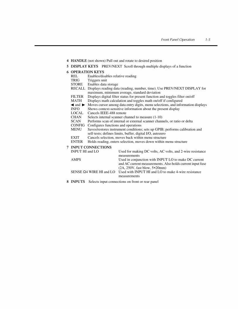
4 HANDLE (not shown) Pull out and rotate to desired position
5 DISPLAY KEYS PREV/NEXT Scroll through multiple displays of a function
6 OPERATION KEYSREL Enables/disables relative readingTRIG Triggers unitSTORE Enables data storageRECALL Displays reading data (reading, number, time). Use PREV/NEXT DISPLAY for
maximum, minimum average, standard deviationFILTER Displays digital filter status for present function and toggles filter on/offMATH Displays math calculation and toggles math on/off if configured
and Moves cursor among data entry digits, menu selections, and information displaysINFO Shows context-sensitive information about the present displayLOCAL Cancels IEEE-488 remoteCHAN Selects internal scanner channel to measure (1-10)SCAN Performs scan of internal or external scanner channels, or ratio or deltaCONFIG Configures functions and operationsMENU Saves/restores instrument conditions; sets up GPIB; performs calibration and
self-tests; defines limits, buffer, digital I/O, autozeroEXIT Cancels selection, moves back within menu structureENTER Holds reading, enters selection, moves down within menu structure
7 INPUT CONNECTIONSINPUT HI and LO Used for making DC volts, AC volts, and 2-wire resistance
measurementsAMPS Used in conjunction with INPUT LO to make DC current
and AC current measurements. Also holds current input fuse (2A, 250V, fast blow, 5×20mm)
SENSE Ω4 WIRE HI and LO Used with INPUT HI and LO to make 4-wire resistance measurements
8 INPUTS Selects input connections on front or rear panel
Front Panel Operation 1-5
WARNING:NO INTERNAL OPERATOR SERVICABLE PARTS,SERVICE BY QUALIFIED PERSONNEL ONLY.WARNING:NO INTERNAL OPERATOR SERVICABLE PARTS,SERVICE BY QUALIFIED PERSONNEL ONLY.
CAUTION:FOR CONTINUED PROTECTION AGAINST FIRE HAZARD,REPLACE FUSE WITH SAME TYPE AND RATING.CAUTION:FOR CONTINUED PROTECTION AGAINST FIRE HAZARD,REPLACE FUSE WITH SAME TYPE AND RATING.
EXTERNALTRIGGER
INPUT
MADE IN U.S.A.
METERCOMPLETE
OUTPUT
INPUT
1100VPEAK
350VPEAK
500VPEAK
AMPS2A MAX
AMPSFUSE
2A, 250V
DIGITAL I/OTRIGGER
LINK
IN OUT
SENSEΩ 4 WIRE
HI LO!
LINE RATING90-134VAC180-250VAC
50, 60, 400HZ55VA MAX
LINE FUSESLOWBLOW
1/2A, 250V
IEEE-488(CHANGE IEEE ADDRESS
WITH FRONT PANEL MENU)
1 2 3
4
5
6 7 8 9
BNC CONNECTIONS
HI
LO (Chassis)
Trigger Reading
>10µsecTTL HI
TTL LO
EXTERNAL TRIGGER INPUT ReadingComplete
METER COMPLETE OUTPUT
>10µsecTTL HI
TTL LO
OPTION SLOT
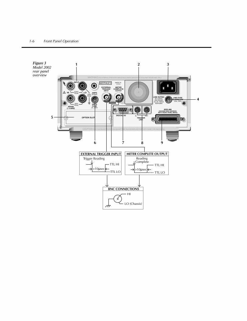
Figure 3Model 2002 rear panel overview
1-6 Front Panel Operation

1 INPUT CONNECTIONSINPUT HI and LO Used for DC volts, AC volts, and 2-wire resistance measure-
mentsAMPS Used with INPUT LO to make DC current and AC current
measurementsSENSE Ω4 WIRE HI and LO Used with INPUT HI and LO to make 4-wire resistance
measurements
2 FAN Keep filter clean to ensure proper instrument cooling
3 POWER LINE INPUT90–134VAC and 180–250VAC (universal); 50, 60, or 400Hz (self-identifying at power-up)WARNING: Connect to grounded outlet using 3-wire power cord
4 LINE FUSE 0.5A, 250V, slow blow, 5×20mm
5 OPTION SLOT An option card installs in this slot
6 AMPS FUSE 2A, 250V, fast blow, 5×20mm
7 DIGITAL I/O A DB-9 connector for the TTL-compatible digital I/O with one input and four outputs
8 TRIGGER LINK IN and OUT Two 8-pin micro DIN connectors for sending and receiv-ing trigger pulses among other instruments
9 IEEE-488 CONNECTOR Connects the instrument to the IEEE-488 (GPIB) busNOTE: Use shielded IEEE-488 cables
Front Panel Operation 1-7

Display
As shown in the Model 2002 front panel overview (Figure 2), the front panel has three lines of display information: the primary display line, the secondary display line, and annunciators.
• Primary Display Line: The top line displays readings along with units. It can also display measurement type (e.g., RMS), “hold”, math operating type, channel number, menu headings and messages. Error and status messages are listed in Section 2 of the User’s Manual.
• Secondary Display Line: The bottom line displays the range, other measurement param-eters (e.g., coupling or ratio), menu items, messages and multiple displays (see MEA-SUREMENT OPTIONS section of this manual). Longer text strings are indicated by arrows on either end of the display line. Use the cursor keys ( and ) to display the additional information.
Note that in certain situations, displayed readings may be expressed in scienti c notation. For example, a reading of +1.0000e-03VDC is interpreted as 1mVDC.
Power-up
Warning Before turning on the Model 2002, make sure it is connected to a grounded power receptacle using the supplied power cord or the equivalent. Failure to properly ground the unit creates a shock hazard that could result in injury or death.
Use the front panel POWER switch to turn power on and off.
During power-up, the Model 2002 performs self-tests on its memory elements. If a failure oc-curs, the instrument momentarily displays an error message and turns on the ERR annunciator. If the instrument passes the self-tests, the rmware revision levels, memory option (if installed), and IEEE-488 address are displayed.
For complete information on the power-up sequence, see Section 2 in the User’s Manual.
Warm-up
The instrument is ready for use as soon as the power-up sequence is completed. However, to achieve rated accuracy, allow the instrument to warm up for four hours. If the instrument has been subjected to extreme temperatures, allow additional time to allow internal temperatures to stabilize.
1-8 Front Panel Operation

Bench defaults
The Model 2002 can save one, v e, or ten user setups in non-volatile memory, depending on the installed memory option. You can select one of the user setups as the power-on default, or have the instrument power up to either of the two factory defaults (optimized for “BENCH” or “GPIB” operation).
Since the basic measurement procedures in this manual assume the BENCH defaults, reset the instrument from the SAVESETUP item of the MAIN MENU by performing the following steps:
1. Press the MENU key to display the main menu:
MAIN MENU
SAVESETUP GPIB CALIBRATION TEST LIMITS STATUS-MSG GENERAL
2. If the SAVESETUP option is not blinking, press the key until it is blinking and then press ENTER to view the setup menu:
SETUP MENU
SAVE RESTORE POWERON RESET
3. Select the RESET option and press ENTER to view the reset menu:
RESET ORIGINAL DFLTS
BENCH GPIB
4. Select the BENCH option and press ENTER. The following message is displayed:
RESETTING INSTRUMENT
Enter to confirm; EXIT to abort
5. Press ENTER to con rm. The display will show DC voltage readings with auto-range enabled.
Other BENCH default settings for DCV include:
• Triggers — Continuous measurements.• Measurement speed (integration time) — Normal, 1 power line cycle.• Digital lter — Advanced, 10 readings, 1% noise tolerance, moving average, enabled.• Display resolution — 7.5 digits.
Note: See MENUS in the MEASUREMENT OPTIONS section of this manual for details on navigating the Main Menu.
Front Panel Operation 1-9

Voltage measurements
Assuming “BENCH” reset conditions, the basic procedure is as follows:
1. Connect test leads to the INPUT HI and LO terminals. Either the front or rear inputs can be used; place the INPUTS button in the appropriate position.
2. Select the measurement function by pressing DCV or ACV.3. The AUTO annunciator indicates that autoranging is enabled. If you want manual rang-
ing, use the RANGE
and
keys to select a measurement range consistent with the expected voltage.
4. Connect test leads to the source as shown in Figure 4.
CAUTION Do not apply more than 1100V peak or 2
×
10
7
V•Hz to the input, or instru-ment damage may occur.
5. Observe the display. If the “Over o w” message is displayed, select a higher range until a normal reading is displayed. Use the lowest possible range for the best resolution.
6. Take a reading from the display.
2001 MULTIMETER
1 2 3 4 5 6 7 8 9 10 1 2 3 4 5 6 7 8 9 10EDIT ERR REM TALK LSTN SRQ REAR REL FILT MATH 4W AUTO ARM TRIG SMPL
Caution: Maximum Input = 1100V peak, 2 x 10⁷ V•Hz
AC VoltageSource
Model 2002
Input Impedence = 1MΩ shunted by <140pF
Figure 4DC and ACvoltage measurements
2001 MULTIMETER
1 2 3 4 5 6 7 8 9 10 1 2 3 4 5 6 7 8 9 10EDIT ERR REM TALK LSTN SRQ REAR REL FILT MATH 4W AUTO ARM TRIG SMPL
Model 2002
Caution : Maximum Input = 1100V peak
DC VoltageSource
Input Resistance = 10MΩ on 1000V and 200V ranges. > 100GΩ on 20V, 2V and 200mV ranges. = 1MΩ on DCV peak spikes measurement.
1-10 Front Panel Operation

Current measurements
Assuming “BENCH” reset conditions, the basic procedure is as follows:
1. Connect test leads to the AMPS and INPUT LO terminals. Either the front or rear inputs can be used; place the INPUTS button in the appropriate position.
2. Select the measurement function by pressing DCI or ACI.3. The AUTO annunciator indicates that autoranging is enabled. If you want manual rang-
ing, use the RANGE
and
keys to select a measurement range consistent with the expected current.
4. Connect test leads to the source as shown in Figure 5.
CAUTION Do not apply more than 2.1A, 250V to the input, or the amps fuse will blow.
5. Observe the display. If the “Over o w” message is displayed, select a higher range until a normal reading is displayed. Use the lowest possible range for the best resolution.
6. Take the reading from the display.
2001 MULTIMETER
1 2 3 4 5 6 7 8 9 10 1 2 3 4 5 6 7 8 9 10EDIT ERR REM TALK LSTN SRQ REAR REL FILT MATH 4W AUTO ARM TRIG SMPL
Model 2002
Caution: Maximum Input = 2.1A
CurrentSource
Figure 5DC and ACcurrent measurements
Front Panel Operation 1-11

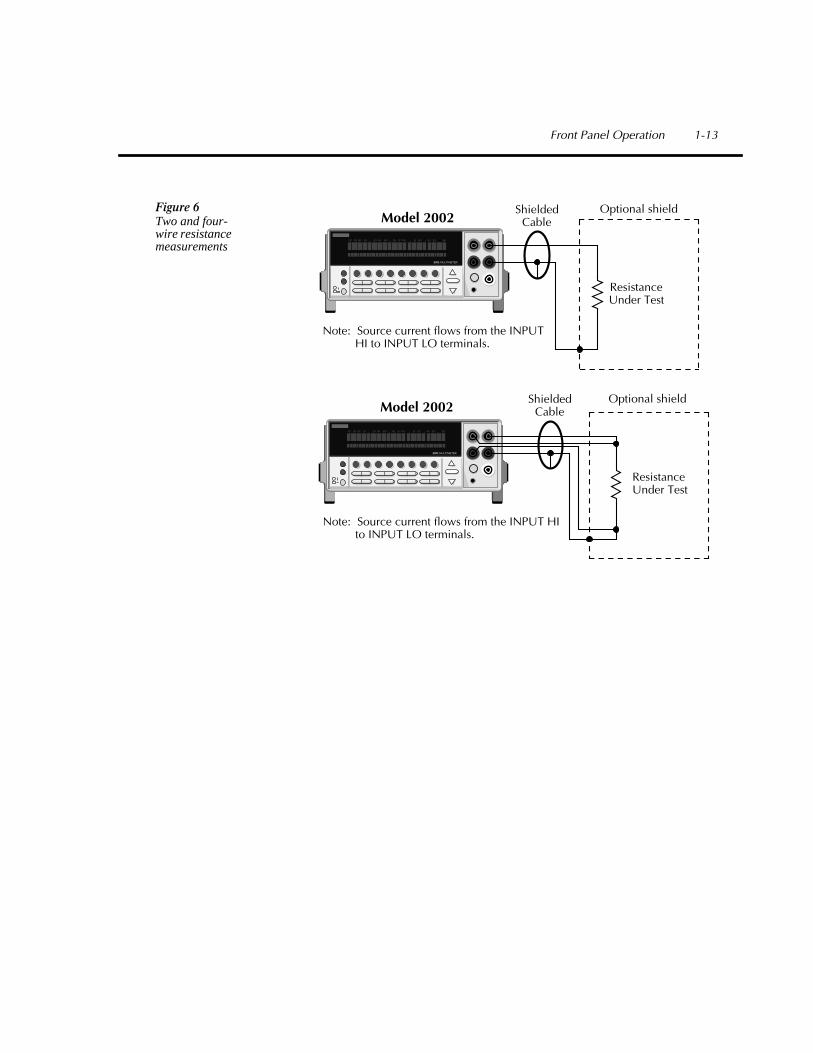
Two and four-wire resistance measurements
Assuming “BENCH” reset conditions, the basic procedure is as follows:
1. Connect test leads to the Model 2002 as follows:A. For 2-wire, connect the test leads to INPUT HI and LO.
B. For 4-wire, connect the test leads to INPUT HI and LO, and SENSE
Ω
4 WIRE HI and LO. Recommended Kelvin test probes include the Keithley Models 5805 and 5806.
Either the front or rear inputs can be used; place the INPUTS button in the appropriate position.
2. Select the measurement function by pressing
Ω
2 or
Ω
4.3. The AUTO annunciator indicates that autoranging is enabled. If you want manual rang-
ing, use the RANGE
and
keys to select a measurement range consistent with the expected resistance.
4. Connect test leads to the resistance as shown in Figure 6.
CAUTION Do not apply more than 1100V peak between INPUT HI and LO, or instru-ment damage may occur.
5. Observe the display. If the “Over o w” message is displayed, select a higher range until a normal reading is displayed. Use the lowest possible range for the best resolution.
6. Take a reading from the display.
Shielding
It helps to shield resistances greater than 100k
Ω
to achieve a stable reading. Place the resis-tance in a shielded enclosure and electrically connect the shield to the INPUT LO terminal of the instrument.
1-12 Front Panel Operation
2001 MULTIMETER
1 2 3 4 5 6 7 8 9 10 1 2 3 4 5 6 7 8 9 10EDIT ERR REM TALK LSTN SRQ REAR REL FILT MATH 4W AUTO ARM TRIG SMPL
Model 2002
ResistanceUnder Test
ShieldedCable
Optional shield
Note: Source current flows from the INPUT HI to INPUT LO terminals.
Figure 6Two and four-wire resistance measurements
2001 MULTIMETER
1 2 3 4 5 6 7 8 9 10 1 2 3 4 5 6 7 8 9 10EDIT ERR REM TALK LSTN SRQ REAR REL FILT MATH 4W AUTO ARM TRIG SMPL
ResistanceUnder Test
ShieldedCable
Optional shield
Note: Source current flows from the INPUT HI to INPUT LO terminals.
Model 2002
Front Panel Operation 1-13

Frequency measurements
The Model 2002 can make frequency measurements from 1Hz to 15MHz through its INPUT HI and INPUT LO terminals, and from 1Hz to 1MHz through its AMPS and INPUT LO termi-nals. Assuming “BENCH” reset conditions, the basic procedure is as follows:
1. Connect test leads to the INPUT HI and LO terminals of the Model 2002. Either the front or rear inputs can be used; place the INPUTS button in the appropriate position.
NOTE
A bench reset defaults the frequency input terminals to INPUT HI and LO.
2. Select the FREQ function.3. Connect test leads to the source as shown in Figure 7 (top).
CAUTION Do not exceed 1100V peak between INPUT HI and INPUT LO, or instru-ment damage may occur.
4. Take a reading from the display.
The procedure for measuring frequency with the AMPS and INPUT LO terminals is similar. However, the FREQ function has to be con gured to use the current terminals (the connection diagram is shown in Figure 7 (lower)). Perform the following steps to select the AMPS and IN-PUT LO terminals:
1. Press the CONFIG key and then the FREQ key.2. Using the cursor keys ( and ), place the cursor on INPUT-TERMINALS and press
ENTER.3. Place the cursor on CURRENT and press ENTER.4. Use the EXIT key to back out of the menu structure.
CAUTION Do not apply more than 2.1A, 250V to the AMPS input, or the amps protec-tion fuse will blow.
1-14 Front Panel Operation
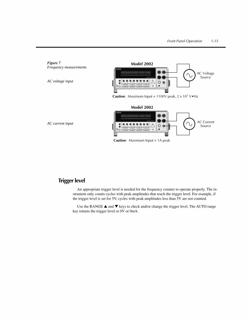
Trigger level
An appropriate trigger level is needed for the frequency counter to operate properly. The in-strument only counts cycles with peak amplitudes that reach the trigger level. For example, if the trigger level is set for 5V, cycles with peak amplitudes less than 5V are not counted.
Use the RANGE and keys to check and/or change the trigger level. The AUTO range key returns the trigger level or 0V or 0mA.
Figure 7Frequency measurements
AC voltage input
AC current input
2001 MULTIMETER
1 2 3 4 5 6 7 8 9 10 1 2 3 4 5 6 7 8 9 10EDIT ERR REM TALK LSTN SRQ REAR REL FILT MATH 4W AUTO ARM TRIG SMPL
Model 2002
Caution: Maximum Input = 1100V peak, 2 x 10⁷ V•Hz
AC VoltageSource
2001 MULTIMETER
1 2 3 4 5 6 7 8 9 10 1 2 3 4 5 6 7 8 9 10EDIT ERR REM TALK LSTN SRQ REAR REL FILT MATH 4W AUTO ARM TRIG SMPL
Model 2002
Caution: Maximum Input = 1A peak
AC CurrentSource
Front Panel Operation 1-15

Temperature measurementsThe Model 2002 measures temperature with two different sensor types: RTDs and thermo-
couples. With RTDs, the Model 2002 can measure temperature between -200°C and +630°C. RTDs can be connected to the input terminals or the optional Model 2001-SCAN scanner card.
With thermocouples connected to the Model 2001-TCSCAN card or an external thermocou-ple card, such as a Model 7057A or 7402 in a Model 7001 or 7002 Switch System, the instru-ment measures temperature over a range that is dependent on the thermocouple type.
Assuming “BENCH’ reset conditions, the basic procedure to measure temperature with a type PT100 4-wire RTD (the default sensor) is as follows:
1. Connect the RTD sensor to the Model 2002 as shown in Figure 8. You can use banana plugs (with the front or rear inputs), or the optional Model 8680 RTD Probe Adapter (with the front inputs). Place the INPUTS button in the appropriate position RTDs can also be connected to the optional Model 2001-SCAN scanner card.
2. Select the TEMP function.
CAUTION Do not exceed 1100V peak between INPT HI and LO, or 350V peak between SENSE Ω4 WIRE HI and LO, or instrument damage may occur.
3. Observe the display. If the “Over o w” message is shown, the RTD might not be connect-ed properly.
4. Take a reading from the display.
The procedure for measuring temperature with 3-wire and 2-wire RTDs is similar and is cov-ered in Section 2 of the User’s Manual.
To measure temperature with thermocouples, you need to connect the thermocouples to a suitable scanner card, such as the Model 2001-TCSCAN or an external card (Model 7057A or 7402). The thermocouple cards use channel 1 as the reference junction and must be con gured on the Model 2002 for TC type, voltage reference and offset. See Section 2 in the User’s Manual for con guration details.
1-16 Front Panel Operation
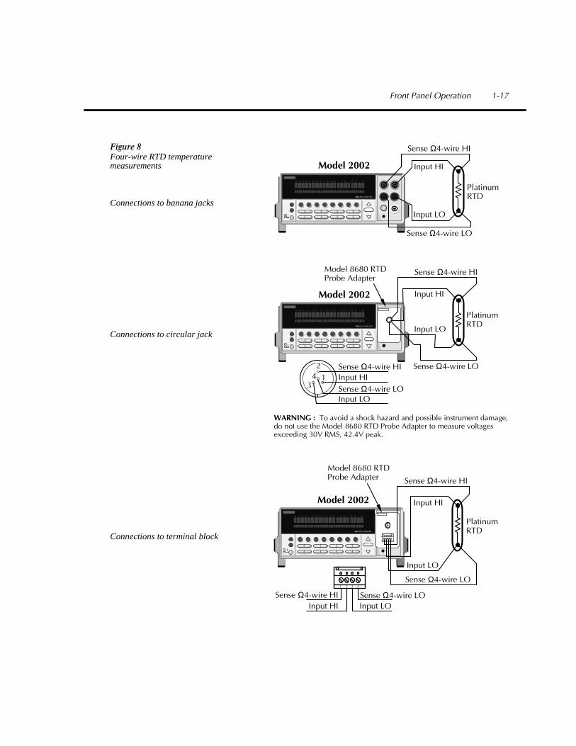
Figure 8Four-wire RTD temperature measurements
Connections to banana jacks
Connections to circular jack
Connections to terminal block
2001 MULTIMETER
1 2 3 4 5 6 7 8 9 10 1 2 3 4 5 6 7 8 9 10EDIT ERR REM TALK LSTN SRQ REAR REL FILT MATH 4W AUTO ARM TRIG SMPL
Model 2002
Sense Ω4-wire HI
PlatinumRTD
Input HI
Input LO
Sense Ω4-wire LO
2001 MULTIMETER
1 2 3 4 5 6 7 8 9 10 1 2 3 4 5 6 7 8 9 10EDIT ERR REM TALK LSTN SRQ REAR REL FILT MATH 4W AUTO ARM TRIG SMPL
Model 2002
PlatinumRTD
Sense Ω4-wire HI
Input HI
Input LO
Sense Ω4-wire LO1
2
34
Sense Ω4-wire HIInput HISense Ω4-wire LOInput LO
WARNING : To avoid a shock hazard and possible instrument damage,do not use the Model 8680 RTD Probe Adapter to measure voltagesexceeding 30V RMS, 42.4V peak.
Model 8680 RTDProbe Adapter
2001 MULTIMETER
1 2 3 4 5 6 7 8 9 10 1 2 3 4 5 6 7 8 9 10EDIT ERR REM TALK LSTN SRQ REAR REL FILT MATH 4W AUTO ARM TRIG SMPL
Model 2002
PlatinumRTD
Sense Ω4-wire HI
Input HI
Input LO
Sense Ω4-wire LO
Sense Ω4-wire HIInput HI
Sense Ω4-wire LOInput LO
1 2 3 4
Model 8680 RTDProbe Adapter
Front Panel Operation 1-17

1-18 Front Panel Operation

2
MeasurementOptions

This section describes the details of making measurements. Configuration options, triggers, reading storage, and scanning are just a few of the topics discussed. You will find this informa-tion useful whether operating the Model 2002 from the front panel or IEEE-488 bus.
Multiple displays
Each measurement function and some operations provide “multiple displays” by using the bottom line of the front panel. These multiple displays provide multiple type measurements, show a reading in a different form, or give additional information about the reading.
A few of the frequently used multiple displays are summarized in this section. All the multi-ple displays are shown in Table 1.
The NEXT and PREV (previous) DISPLAY keys scroll through the multiple displays for the selected function or operation. The multiple display mode can be cancelled by pressing and holding in either key.
2-2 Measurement Options

Table 1
Multiple displays by function
Function Next display
All
DC voltage
AC voltage
DC current
AC current
2-wire resistance
4-wire resistance
Frequency
Temperature
Data storage buffer
Bar graphZero-centered bar graphMaximum and minimum valuesRelative and actual valuesCalculated and actual values (see Note 1)Limts bar graph (see Note 1)Adjacent channel readings (see Note 2)
DC volts, AC ripple voltage and frequencyPositive peak spikes and highest valueNegative peak spikes and lowest valuePositive and negative peak spikes
AC RMS voltage, frequency, and crest factorAC RMS, average, and peak voltages
(none specific to function)
AC RMS (or average) current and frequencyAC RMS and average current
Source currentVoltage drop across DUT
Source currentVoltage drop across DUTLead resistance
Period calculationTrigger level
Celsius, Fahrenheit, and Kelvin unitsRTD resistance (or thermocouple voltage)Reference junction (thermocouples only)
Maximum and minimum valuesAverage and standard deviation
Notes:1. Multiple displays for calculated values and limits bar graph are not available for the fre-
quency function.2. The multiple display for adjacent channel readings is not available for the DC and AC
current functions.
Measurement Options 2-3

Bar Graph — The bar graph is a graphical represen-tation of the reading with zero at the left end. Each full segment of the bar represents approximately 4% of the range limit.
2002 MULTIMETER
FILT 4W ARM
Zero-centered Bar Graph — The zero-centered bar graph is a graphical representation of the reading using plus minus limits with zero in the center. Each full seg-ment represents 10% of the limit.
2002 MULTIMETER
FILT 4W ARM
Maximum and Minimum — This display shows the maximum and minimum readings that have oc-curred since the display was entered. Maximum and minimum values are reset by pressing the present func-tion key or by leaving the display.
2002 MULTIMETER
FILT 4W ARM
Relative and Actual — This display is used with the rel (relative) feature. While the top line shows the result of the rel operation, the bottom line shows the ac-tual (raw) reading.
2002 MULTIMETER
FILT ARM
2-4 Measurement Options

Calculated and Actual — This display is used with a math calculation. While the top line provides the re-sult of the math calculation, the bottom line provides the raw reading.
2002 MULTIMETER
Buffer — These bottom line displays are used when recalling readings from the data store buffer. They pro-vide the maximum, minimum, average and standard deviation for the readings stored in the buffer.
2002 MULTIMETER
2002 MULTIMETER
FILT ARM
FILT ARM
Measurement Options 2-5

Menus
There are two basic menu structures used by the Model 2002: the main menu and the CON-FIGure menus. The main menu accesses items for which there are no dedicated keys; the CON-FIGure menus configure measurement functions and other instrument operations.
Table 2 summarizes main menu selections. Tables 3 and 4 show configuration settings for the measurement functions and instrument operations.
Table 2
Summary of main menu
Option Description
SAVESETUP
GPIB
CALIBRATION
TEST
LIMITS
STATUS-MSG
GENERAL
Save and restore setups stored in memory, set power-on defaults, and return unit to default conditions.
Check or change IEEE-488 bus address, configure unit for talk-only operation, select data elements, and display the status byte.
Calibrate the Model 2002 (see Calibration Manual), and check calibration date.
Perform self-tests (see Repair Manual).
Configure unit to perform limit tests.
Enable/disable status message mode.
Control output lines and read input lines of digital I/O port, check serial number of unit and firmware revision levels, control line-sync and autozero, configure times-tamp, select decimal point character, and set real-time clock.
2-6 Measurement Options

Table 3
Configuration settings for each measurement function
Function Speed FilterReso-lution Coupling
Max. signal level
Units (V, db, dbm)
AC type
Offsetcomp.
Max. auto range
Sensor
DC Voltage
AC Voltage
2-Wire Resistance
4-Wire Resistance
DC Current
AC Current
Frequency/Period
Temperature
•
•
•
•
•
•
•
•
•
•
•
•
•
•
•
•
•
•
•
•
•
•
•
•
•
•
•
•
•
•
•
•
•
•
The 2002 allows each measurement function to be configured independently, letting you set each function as desired. For example, if DCV is set for 7
½
digits using 10 power line cycles, ACV can be set to 5
½
digits at 0.1 power line cycle.
Table 4
Configuration settings for instrument operations
Option Description
CONFIG REL
CONFIG TRIG
CONFIG STORE
CONFIG FILTER
CONFIG MATH
CONFIG CHAN
CONFIG SCAN
CONFIG NEXT
Set rel (relative) value and enable.
Configure measure layer, scan layer and arm layer of trig-ger model.
Enable/disable burst mode, select data grouping, set buffer control, configure timestamp, clear buffer, set buffer size and select buffer feed.Select auto, averaging, advanced or averaging-mode filter.
Select and configure math calculation; polynomial, percent or percent deviation.
Configure unit for internal channels or external channels, and save and restore an alternate function.
Configure scan for internal or external channels. Configure unit for ratio or delta calculations.
Change the scale for the zero-center bar graph.
Measurement Options 2-7

Navigating menus
Use the following rules to navigate through the menu structures. Table 5 summarizes the front panel keys used for navigation.
1. From the instrument’s normal state of displaying readings, you can:
• View a configuration menu by pressing CONFIG and then the desired function or op-eration key (DCV, TRIG, etc.).
• View the top level of the main menu by pressing the MENU key.
2. The unit is returned to the normal reading display by:
• Pressing EXIT or MENU from the top level of the main menu.• Pressing EXIT from the top level of a configuration menu.• Pressing a measurement function key from within a menu.
3. Pressing the ENTER key selects an item and, if further definition is needed, moves down within the menu structure. Pressing the EXIT key backs up within a menu structure.
4. The cursor position is denoted by a blinking menu item or parameter. The cursor is moved from one item to the next using the cursor keys ( and ) . To select an item, highlight it with the cursor, then press ENTER.
5. A displayed arrow ( and ) on the bottom line indicates there is more information or additional menu items to select from. When “ ” is displayed, use the cursor key. The cursor keys have an auto-repeat feature.
6. A numeric parameter is keyed in by placing the cursor on the digit to be changed, and pressing the RANGE
or
keys to increment or decrement the digit.7. A change is only executed when the ENTER key is pressed. Entering an invalid param-
eter generates an error, and the entry is ignored. Changes are also ignored if an EXIT is performed.
8. The INFO key can be used anywhere in a menu to display helpful information messages concerning operation. To cancel an information message and remain in the menu, press INFO a second time, EXIT, or ENTER. Pressing a function key cancels INFO and a menu, and returns the instrument to a reading display.
2-8 Measurement Options

Table 5
Menu summary
Action Description
CONFIG-(function)
MENU
or
RANGE
RANGE
ENTER
EXIT
INFO
Press the CONFIG key, then a function key (e.g., DCV) to view the top level of a function configuration menu.
Press the MENU key to view the top level of the main menu. The operations that have no corresponding key are included in the main menu.
Use the cursor keys to move the highlighted cursor among menu selections, or the digits of a parameter value, or change channels on the scanner.
Use the RANGE keys to increment and decrement digits of a parameter value.
Accepts menu selection or data entry.
Cancels changes menu selection. Also returns you to the previous menu level.
Displays context-sensitive information about the present menu level. Toggles information message on/off.
Measurement Options 2-9

Relative
Rel subtracts a reference value from actual readings. When rel is enabled, the instrument uses the present reading as a relative value. Subsequent readings will be the difference between the actual input value and the rel value.
Actual Input – Reference = Displayed Reading
Thus, when you perform a zero correction for DCV,
Ω
2, and
Ω
4 measurements by enabling REL, the displayed offset becomes the reference value. Subtracting the offset from the actual input zeroes the display.
The rel (relative) operation is enabled by pressing the REL key (REL annunciator turns on). Pressing REL a second time disables rel. You can also enter and enable a rel value from the CONFIG-REL display.
A rel value can be established for each measurement function. The state and value of rel for each measurement function are saved when changing functions. Once a rel value is established for a measurement function, the value is the same for all ranges.
Configuring Rel
To check or change a rel value for a measurement function, perform the following steps:
1. Select the desired measurement function.2. Press the CONFIG key and then the REL key to display the present rel value.3. Use the cursor keys ( and ) and the RANGE keys to change the rel value and press
ENTER. The instrument will return to the normal display state with rel enabled.
2-10 Measurement Options

Trigger
The following overview is intended to acquaint you with basic triggering. For a complete ex-planation, see the Model 2002 User’s Manual. The simplified model for triggering is shown in Figure 9. It is known as the trigger model.
Idle
The instrument is in idle whenever it is not within one of the layers of the model. The front panel ARM indicator is off when in idle.
When the Model 2002 is taken out of idle by pressing TRIG (or sending :INIT or :INIT:CONT ON over the bus), the ARM indicator turns on and operation proceeds into the Arm Layer.
ArmLayer
ScanLayer
MeasureLayer
Yes
No
ArmCount
ScanCount
MeasureCount
Yes
No
Yes
No
DeviceAction
OutputTrigger
Idle
AnotherArm
?
AnotherScan
?
MeasureEvent
ArmEvent
ScanEvent
AnotherMeasure-
ment?
Figure 9Simplifiedtrigger model
Measurement Options 2-11

Trigger model layers
The trigger model has three layers: the Arm Layer, Scan Layer and Measure Layer. For IEEE-488 bus operation, these layers are known as Arm Layer 1, Arm Layer 2 and the Trigger Layer.
Once the Model 2002 is taken out of idle, operation proceeds through the layers of the trigger model down to the device action where a measurement occurs.
Control source
In general, each layer contains a control source which holds up operation until the pro-grammed event occurs. The control sources are described as follows:
• Immediate –Event detection is immediately satisfied, allowing operation to continue.• Manual – Event detection is satisfied by pressing the TRIG key.• GPIB – Event detection is satisfied when a bus trigger (GET or *TRG) is received.• RT-Clock – Event detection in the Arm Layer is satisfied when the programmed time and
date occur. (Not available in the Scan Layer and Measure Layer.)• Timer – Event detection is immediately satisfied on the initial pass through the layer.
Each subsequent detection is satisfied when the programmed timer interval elapses. (Not available in the Arm Layer.)
• External – Event detection is satisfied when an input trigger via the EXTERNAL TRIG-GER connector is received.
• TrigLink – Event detection is satisfied when an input trigger via the TRIGGER LINK is received.
• Hold – With this selection, event detection is not satisfied by any of the above con-trol source events and operation is held up.
2-12 Measurement Options

Device action
The primary device action is a measurement. However, the device action could include a function change and a channel scan (if scanner is enabled). A channel is scanned (closed) before a measurement is made. When scanning internal channels, the previous channel opens and the next channel closes (break-before-make). Also included in the device action is the internal set-tling time delay for the relay.
Output trigger
After each measurement (device action), an output trigger pulse occurs and is available at the rear panel of the Model 2002. When used with an external scanner (such as a Model 7001 or 7002 Switch System), each output trigger would be used to select the next channel in a scan (see EXTERNAL SCANNING in the MEASUREMENT OPTIONS section of this manual).
Counters
All three layers use programmable counters that allow operation to return to or stay in the re-spective layer. For example, programming the Measure Layer counter to infinite keeps opera-tion in the Measure Layer. After each device action, operation loops back to the Trigger Layer control source. A counter resets when operation loops back to a higher layer (or idle).
Bench default trigger model setup
The bench default setup takes the Model 2002 out of idle, sets the control sources of all layers to Immediate, and sets the Measure Layer counter to infinite. With this trigger model setup, op-eration simply falls into the Measure Layer (and stays there) to make continuous measurements.
Measurement Options 2-13
Speed
SPEED sets the integration time of the A/D converter, the period of time the input signal is measured. The SPEED can be set for each measurement function except FREQ. The integration time is specified in parameters based on a number of power line cycles (NPLC), where one PLC for 60Hz is 16.67msec and one PLC for 50Hz and 400Hz is 20msec.
In general, the fastest integration time (0.01 PLC) results in increased reading noise and less usable resolution, while the slowest integration time (50 PLC) provides the best common-mode and normal-mode rejection. In between settings are a compromise between speed and noise.
Configuring speed
Each measurement function, except FREQ, can have its own unique integration time. Speed is set from the configure function menu structures. The procedure is summarized as follows:
1. Press the CONFIG key and then the desired function key (DCV, ACV, etc.).2. Using the cursor keys ( and ), select SPEED and press ENTER to display the fol-
lowing speed options:
NORMAL: Sets the integration time to 1 PLC.
FAST: Sets the integration time to 0.01 PLC.
MEDIUM: Sets the integration time to 0.1 PLC.
HIACCURACY: Sets the integration time to 50 PLC.
SET-SPEED-EXACTLY: This options prompts you to enter a PLC value (0.01 to 50).
SET-BY-RESOLUTION: Automatically optimizes the integration time for the present resolution setting (see the User’s Manual).
3. Use the menu items to configure speed. A menu item is selected by placing the cursor (using and keys) on it and pressing ENTER. Parameter values are changed using the cursor keys and the RANGE keys, and then pressing ENTER. See MENUS if you need more information to navigate through the menu structure.
NOTE
For more information, see SPEED in Section 2 of the User’s Manual.
2-14 Measurement Options

Resolution
Except for FREQ, TEMP and some special cases for ACV, all functions can operate from 3.5 to 8.5 digits of resolution. Each function can have its own unique resolution setting.
Configure resolution
Perform the following steps to set resolution for a measurement function:
1. Press the CONFIG key and then the desired function key (DCV, ACV, etc.).2. Using the cursor keys ( and ), select RESOLUTION and press ENTER to dis-
play the following resolution options:3.5d to 8.5d: Select one of these options to set the display resolution.
AUTO: This option automatically optimizes the resolution for the present integration time (speed) setting (see the User’s Manual).
3. Set resolution by placing the cursor (using and keys) on the menu option press-ing ENTER. See MENUS if you need more information to navigate through the menu structure.
NOTE
For more information, see RESOLUTION in Section 2 of the User’s Manual.
Measurement Options 2-15

Filter
Filtering stabilizes noisy measurements. The Model 2002 uses a digital filter, which is based on reading conversions. The displayed, stored, or transmitted reading is an average of a number of reading conversions. When a filter is enabled by pressing FILTER (FILT annunciator turns on), the selected filter configuration for that measurement function is in effect. Pressing FILTER a second time disables the filter.
Filter types
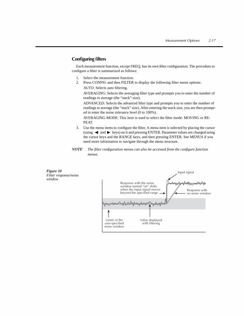
The Model 2002 has two types of digital filters; averaging and advanced. Both types are a simple average of 1 to 100 reading conversions. The difference is a user-programmed noise “window” for the advanced filter. The noise window (expressed as a percentage of range) allows a faster response time to large signal step changes. See the User’s Manual for complete informa-tion on filter types.
Filter modes
There are two filter modes: moving or repeating. The moving filter uses a first-in, first-out stack. When the stack becomes full, the measurement conversions are averaged, yielding a read-ing. For each subsequent conversion, the new conversion is placed into the stack, the oldest con-version is discarded, and a new reading is averaged.
For the repeating filter, the stack is filled and the conversions are averaged to yield a reading. The stack is then cleared and the process starts over. See the User’s Manual for complete infor-mation on filter modes.
Auto filter
With auto filtering, the instrument automatically configures the filter based on the selected function and measurement type.
2-16 Measurement Options
Configuring filters
Each measurement function, except FREQ, has its own filter configuration. The procedure to configure a filter is summarized as follows:
1. Select the measurement function.2. Press CONFIG and then FILTER to display the following filter menu options:
AUTO: Selects auto filtering.
AVERAGING: Selects the averaging filter type and prompts you to enter the number of readings to average (the “stack” size).
ADVANCED: Selects the advanced filter type and prompts you to enter the number of readings to average (the “stack” size). After entering the stack size, you are then prompt-ed to enter the noise tolerance level (0 to 100%).
AVERAGING-MODE: This item is used to select the filter mode: MOVING or RE-PEAT.
3. Use the menu items to configure the filter. A menu item is selected by placing the cursor (using and keys) on it and pressing ENTER. Parameter values are changed using the cursor keys and the RANGE keys, and then pressing ENTER. See MENUS if you need more information to navigate through the menu structure.
NOTE
The filter configuration menus can also be accessed from the configure function menus.
Value displayed with filtering
Response with the noise window turned “on” shiftswhen the input signal moves beyond the specified range
Response withno noise window
Limits of theuser-specified noise window
Input signalFigure 10Filter response/noise window
Measurement Options 2-17

Buffer (Data Store)
The Model 2002 has a buffer to store readings at two different rates: normal and burst modes. The maximum number of readings that can be stored depends on the installed memory option (standard, MEM1 or MEM2) and the user-programmable data group (full or compact). Storage capacity is summarized in Table 6.
A full data group includes the reading, units, channel#, reading#, timestamp, and status. A compact data group does not include the channel# or timestamp. The data group and other buffer parameters are configured from the CONFIG DATA STORE menu structure.
Normal mode
The following procedure to store readings at the normal rate uses a typical data store config-uration: a user-defined number of readings wil be stored in the buffer (fill-and-stop). All aspects of data store configuration and opeation are detailed in Section 2 of the User’s Manual.
1. Set up the instrument for the desired measurements (function, range, etc.).2. Configure the data store as follows. Note that a menu item is selected by placing the cur-
sor (using and keys) on it and pressing ENTER. See MENUS if you need more information to navigate through the menu structure.• Press CONFIG• Press STORE• Select DATA-GROUP• Select FULL or COMPACT• Select CONTROL• Select FILL-AND-STOP
Note: If you selected the FULL data group, continue on to configure the timestamp. Oth-erwise, press EXIT to back out of the menu structure.
• Select TIMESTAMP• Select TYPE• Select REAL-TIME• Select FORMAT• Select ABSOLUTE
Use the EXIT key to back out of the menu structure.
3. Press STORE. The presently programmed buffer size (number of readings to store) is displayed. If desired, use the cursor keys and the RANGE keys to change the buffer size. (Incrementing the most significant digit changes buffer size to the maximum.)
Table 6
Memory options
ModelSize
(Bytes) 4
½
-Digit6
½
-Digit w/time stamp Type
20022002/MEM12002/MEM2
8k32k128k
2,0276,90929,908
4041,3815,980
volatilenon-volatilenon-volatile
2-18 Measurement Options
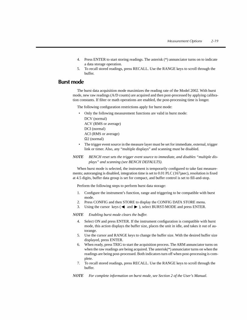
4. Press ENTER to start storing readings. The asterisk (*) annunciator turns on to indicate a data storage operation.
5. To recall stored readings, press RECALL. Use the RANGE keys to scroll through the buffer.
Burst mode
The burst data acquisition mode maximizes the reading rate of the Model 2002. With burst mode, new raw readings (A/D counts) are acquired and then post-processed by applying calibra-tion constants. If filter or math operations are enabled, the post-processing time is longer.
The following configuration restrictions apply for burst mode:
• Only the following measurement functions are valid in burst mode:
DCV (normal)ACV (RMS or average)DCI (normal)ACI (RMS or average)
Ω
2 (normal)
• The trigger event source in the measure layer must be set for immediate, external, trigger link or timer. Also, any “multiple displays” and scanning must be disabled.
NOTE
BENCH reset sets the trigger event source to immediate, and disables “multiple dis-plays” and scanning (see BENCH DEFAULTS).
When burst mode is selected, the instrument is temporarily configured to take fast measure-ments; autoranging is disabled, integration time is set to 0.01 PLC (167µsec), resolution is fixed at 4.5 digits, buffer data group is set for compact, and buffer control is set to fill-and-stop.
Perform the following steps to perform burst data storage:
1. Configure the instrument’s function, range and triggering to be compatible with burst mode.
2. Press CONFIG and then STORE to display the CONFIG DATA STORE menu.3. Using the cursor keys ( and ), select BURST-MODE and press ENTER.
NOTE
Enabling burst mode clears the buffer.
4. Select ON and press ENTER. If the instrument configuration is compatible with burst mode, this action displays the buffer size, places the unit in idle, and takes it out of au-torange.
5. Use the cursor and RANGE keys to change the buffer size. With the desired buffer size displayed, press ENTER.
6. When ready, press TRIG to start the acquisition process. The ARM annunciator turns on when the raw readings are being acquired. The asterisk(*) annunciator turns on when the readings are being post-processed. Both indicators turn off when post-processing is com-plete.
7. To recall stored readings, press RECALL. Use the RANGE keys to scroll through the buffer.
NOTE
For complete information on burst mode, see Section 2 of the User’s Manual.
Measurement Options 2-19

Math
The MATH key lets you perform math operations on single readings and display the result. The three math calculations that are configured from the CONFIGURE MATH menu structure are:
Polynomial:
where: X is the normal display readinga2, a1, and a0 are user entered constantsY is the displayed result
Percent:
where: Input Reading is the normal display readingTarget Value is the user entered constantPercent is the displayed result
Percent Deviation:
where: X is the normal display readingY is the REL value for the selected functionPD is the displayed result (percent deviation)
Selecting and configuring math
The procedure to select and configure a math calculation is summarized as follows:
1. Press CONFIG and then MATH to display the following math filter menu options:
NONE: Select no calculation when the MATH key is pressed.
POLYNOMIAL: Select the polynomial calculation and enter the constants (a2, a1, and a0).
PERCENT: Select the percent calculation and enter the target value (reference).
PERCENT DEVIATION: Select the percent deviation calculation.
2. Use the menu items to select and configure math. A menu item is selected by placing the cursor (using and keys) on it and pressing ENTER. Parameter values are changed using the cursor keys and the RANGE keys, and then pressing ENTER. See MENUS if you need more information to navigate through the menu structure.
Y a2( )X2
a1( )X a0( )+ +=
PercentInput ReadingTarget Value ----------------------------------
100
×
=
PDX Y–( )
Y------------------ 100×=
2-20 Measurement Options

Enabling math
The selected math calculation is enabled by simply pressing the MATH key. When enabled, the MATH annunciator turns on and the calculation type (NONE, POLY, %, or % DEV) is dis-played. Also, one of the following messages is briefly displayed:
Math EnabledDisplay = NONE (reading)
Math EnabledDisplay = POLY (reading)
Math EnabledDisplay = % (reading)
Math EnabledDisplay = % DEV (reading)
Math is disabled by pressing MATH a second time.
Additional math operations
In addition to the math performed on single readings described above, the Model 2002 has these math operations:
• Math performed on buffered readings (maximum and minimum values, average, and standard deviation).
• Math performed on single readings as part of a pass/fail limits test.• Math performed on scanned readings (ratio and delta).
NOTE
Complete information on MATH is provided in Section 2 of the User’s Manual.
Figure 11Combining math calculations
MathPolynomial,
Percent,Percent Deviation
Ratio,Delta
Value DisplayedRawMeasurement
Multiple DisplaysMAX, MIN
SecondMeasurement
Measurement Options 2-21

Internal scanning
The Model 2002 can be used with a scanner card (such as the Model 2001-SCAN or 2001-TCSCAN) installed in the option slot of the instrument. This section provides basic information for scanning internal channels. If the scanner card is not already installed, refer to the scanner card instruction manual.
NOTE
For complete information on scanning (internal and external), refer to Section 2 in the User’s Manual, and the scanner card instruction manuals.
NOTE
The following steps assume that the Model 2002 is set to the BENCH reset default conditions (see BENCH DEFAULTS).
HI
LOChannel 1
HI
LOChannel 5
HI
LOOUT A
HILO
OUT B
HILO
Channel 6
HILO
Channel 10
2-POLE4-POLE
Channels 2–4
Channels 7–9
ReferenceOutput
Channel 1
HILO
Channel 5HILO
OUT A
HILO
OUT B
HILO
Channel 6
HILO
Channel 10
2-POLE4-POLE
Channels 2–4
Channels 7–9
Figure 12
Model 2001-SCAN and Model2001-TCSCAN
2-22 Measurement Options

Configure internal channels
A unique measurement function can be assigned to each of the internal scanner card channels. For example, DCV can be assigned to channels 1 and 2, and
Ω
2 can be assigned to channels 3 and 4. Also, scanner card channels can be skipped during the scan by designating them as no channels (---).
Perform the following steps to configure internal channels:
1. Press CONFIG and then CHAN to display the CONFIGURE CHANNELS menu.2. Using the cursor keys ( and ), select INTERNAL-CHANS and press ENTER to
display the currently selected function for each channel.3. Function assignments can be changed by placing the cursor on the channel and then us-
ing the RANGE keys (
and
) to display the desired function. Select “---” if you wish to skip the channel during the scan.
4. With the desired function assignments displayed, use the EXIT key to back out of the menu structure.
Configure scan
Perform the following steps to configure the Model 2002 for an internal scan:
1. Press CONFIG and the SCAN to display the SCAN OPERATION menu options.2. Use the cursor keys ( and ) to select INTERNAL and press ENTER.
Perform the scan
Perform the following steps to scan internal channels:
1. Press SCAN to display the currently programmed scan count. The scan count specifies the number of scans to be performed.
2. To change the scan count, use the cursor keys ( and ) and RANGE keys (
and
). Press ENTER to continue.3. You will then be asked if you wish to use the scan timer to provide a time interval be-
tween scans.A. Yes – If you wish to use the scan timer, select YES and press ENTER to display the
present interval (in seconds). To change the interval, use the cursor keys and RANGE keys. Press ENTER to continue.
B. No – If you do not wish to use the scan timer, select NO and press ENTER.4. You will then be asked if you wish to store the readings in the buffer.
A. Yes – If you want to use the buffer, select YES and press ENTER. A message indi-cating how many readings will be stored in the buffer is displayed. Press ENTER to continue.
B. No – If you do not wish to use the buffer, select NO and press ENTER.5. With the message “Press ENTER to begin” displayed, press ENTER to start the scan
process. If using the buffer, readings can be recalled by pressing RECALL and using the RANGE keys to scroll through the data points.
Measurement Options 2-23

Close/Open channels
The CHAN key is used to close an internal channel or channel pair (for 4-wire functions), or open any internal closed channel or channel pair. Perform the following steps to close or open channels:
1. Press CHAN to display the following CHANNEL SELECTION options:
CLOSE-CHANNEL: Use to close a channel or channel pair on the internal scanner card.
OPEN-ALL-CHANNELS: Opens all channels on the scanner card.
2. Select the desired option and press ENTER. Selecting CLOSE-CHANNEL prompts you to enter the channel to be closed. Use the cursor keys and RANGE keys to display the channel number and press ENTER. The number of the closed channel will be displayed along with the reading.
NOTE
If a 4-wire function is selected, both the selected channel and the paired channel will close. Channel pairs are 1-6, 2-7, 3-8, 4-9 and 5-10.
2-24 Measurement Options
Ratio and delta calculations
With RATIO or DELTA selected from the SCAN OPERATION menu, the Model 2002 can measure two specified internal scanner channels (reference channel and measure channel) and then compute the ratio or difference (delta) between them. Valid measurement functions for ratio and delta include DCV,
Ω
2 and
Ω
4.
Ratio and delta are calculated as follows:
Perform the following steps to perform ratio or delta calculations:
1. Select and configure ratio or delta as follows. Note that a menu item is selected by plac-ing the cursor (using and keys) on it and pressing ENTER. See MENUS if you need more information to navigate through the menu structure.
• Press CONFIG• Press SCAN• Select RATIO or DELTA• Select MEASURE• Select CH1, 2, 3, 4, 5, 6, 7, 8, 9 or 10• Select REFERENCE• Select CH1, 2, 3, 4, 5, 6, 7, 8, 9 or 10• Select FUNCTION• Select DCV,
Ω
2 or
Ω
4
Use the EXIT key to back out of the menu structure.
2. Press SCAN to halt triggers (instrument goes into idle).3. To start ratio or delta measurements, press SCAN or TRIG. The displayed readings are
the result of the ratio or delta calculation.4. To stop ratio or delta measurements, press EXIT.
RatioMeasureReference------------------------=
Delta Measure Reference–=
Measurement Options 2-25

External scanning
The Model 2002 can be used with a scanner card (such as the Model 7011 Multiplexer Card) installed in an external scanning mainframe (Model 7001 or 7002 Switch System). With the use of external triggering, the Model 2002 can measure and store each scanned channel.
NOTE
For complete information on scanning (external and internal), refer to Section 2 in the User’s Manual, and the switch system and scanner card instruction manual.
NOTE
The following steps assume that the Model 2002 is set to the BENCH reset default conditions (see SETTING UP BENCH DEFAULTS) and the Model 7001/2 is set to the RESET default conditions.
Trigger connections
If using Trigger Link, connect the Model 2002 to the switch system as shown in Figure 13. If using conventional external triggering, connect the instruments as shown in Figure 14. Detailed information on triggers is provided in Section 2 of the User’s Manual.
WARNING:NO INTERNAL OPERATOR SERVICABLE PARTS,SERVICE BY QUALIFIED PERSONNEL ONLY.WARNING:NO INTERNAL OPERATOR SERVICABLE PARTS,SERVICE BY QUALIFIED PERSONNEL ONLY.
CAUTION:FOR CONTINUED PROTECTION AGAINST FIRE HAZARD,REPLACE FUSE WITH SAME TYPE AND RATING.CAUTION:FOR CONTINUED PROTECTION AGAINST FIRE HAZARD,REPLACE FUSE WITH SAME TYPE AND RATING.
MADE IN USA
7001 or 7002 Switch SystemWARNING:NO INTERNAL OPERATOR SERVICABLE PARTS,SERVICE BY QUALIFIED PERSONNEL ONLY.WARNING:NO INTERNAL OPERATOR SERVICABLE PARTS,SERVICE BY QUALIFIED PERSONNEL ONLY.
CAUTION:FOR CONTINUED PROTECTION AGAINST FIRE HAZARD,REPLACE FUSE WITH SAME TYPE AND RATING.CAUTION:FOR CONTINUED PROTECTION AGAINST FIRE HAZARD,REPLACE FUSE WITH SAME TYPE AND RATING.
2002 Multimeter
Trigger Link Trigger
Link Cable(8501)
Trigger Link
OUTIN
IN OUT
Figure 13Trigger con-nections using trigger link
2-26 Measurement Options

Configure external channels
A unique measurement function can be assigned to each of the external scanner card chan-nels. For example, DCV can be assigned to channels 1 and 2, and
Ω
2 can be assigned to channels 3 and 4. Also, scanner card channels can be skipped during the scan by designating them as no channels (---).
Perform the following steps to configure external channels:
1. Press CONFIG and then CHAN to display the CONFIGURE CHANNELS menu op-tions.
2. Using the cursor keys ( and ), select EXTERNAL-INPUTS and press ENTER to display the number of external inputs to be scanned.
3. Use the cursor keys and the RANGE keys to display the number of channels to be scanned and press ENTER. For example, if the scan list is going to consist of 10 chan-nels, then set the number of external inputs to 10.
4. You will then have the opportunity to set a unique measurement function for each exter-nal channel.A. DEFAULT – To assign the presently selected function to all external channels, se-
lect DEFAULT and press ENTER.B. CHOOSE-FUNCTIONS – To change function assignments, perform the following
steps:a. Select CHOOSE-FUNCTIONS and press ENTER. You can use RANGE keys
to check the present function assignment for each external channel.b. To change a function assignment, use the RANGE keys to display the channel
and press ENTER.c. For the displayed channel, place the cursor on the desired function and press
ENTER.d. Repeat steps b and c for other channels.
WARNING:NO INTERNAL OPERATOR SERVICABLE PARTS,SERVICE BY QUALIFIED PERSONNEL ONLY.WARNING:NO INTERNAL OPERATOR SERVICABLE PARTS,SERVICE BY QUALIFIED PERSONNEL ONLY.
CAUTION:FOR CONTINUED PROTECTION AGAINST FIRE HAZARD,REPLACE FUSE WITH SAME TYPE AND RATING.CAUTION:FOR CONTINUED PROTECTION AGAINST FIRE HAZARD,REPLACE FUSE WITH SAME TYPE AND RATING.
MADE IN USA
7001 or 7002 Switch SystemWARNING:NO INTERNAL OPERATOR SERVICABLE PARTS,SERVICE BY QUALIFIED PERSONNEL ONLY.WARNING:NO INTERNAL OPERATOR SERVICABLE PARTS,SERVICE BY QUALIFIED PERSONNEL ONLY.
CAUTION:FOR CONTINUED PROTECTION AGAINST FIRE HAZARD,REPLACE FUSE WITH SAME TYPE AND RATING.CAUTION:FOR CONTINUED PROTECTION AGAINST FIRE HAZARD,REPLACE FUSE WITH SAME TYPE AND RATING.
2002 Multimeter
ChannelReady
7051-2BNC to BNC
Cables (2)
ExternalTrigger Input
ExternalTrigger
MeterCompleteOutput
Figure 14Trigger con-nections using conventional external trig-gering
Measurement Options 2-27

e. Use the EXIT key to back out of the menu structure.
Configure scan
Perform the following steps to configure the Model 2002 for an external scan:
1. Press CONFIG and then SCAN to display the SCAN OPERATION menu options.2. Use the cursor keys ( and ) to select EXTERNAL and press ENTER.
Perform the scan
Perform the following steps to scan external channels. Note that menu items are selected by placing the cursor on it and pressing ENTER. A parameter value is changed by using the RANGE keys and pressing ENTER.
1. Model 2002 – Press SCAN to display the “CONFIG EXT SCANNER; Reset scanner” message.
2. Switch System – If not already done, reset the Model 7001/2 as follows:
• Press MENU• Select SAVESETUP• Select RESET• Select ENTER• Select ENTER
Use the EXIT key to back out of the menu structure.
3. Model 2002 – Press ENTER to display the next message; “CONFIG EXT SCANNER; Set CHAN COUNT to infinite”.
4. Switch System – Set the channel count to infinite as follows:
• Press SCAN• Select SELECT-CONTROL• Select NUMBER-OF-CHANS• Select CHAN-COUNT• Select INFINITE
Note: Do not exit from the menu structure after selecting an infinite channel count.
5. Model 2002 – Select the appropriate trigger source. If using the Trigger Link, select TRIGLINK. If you are instead using conventional external triggering, select EXTER-NAL. The “CONFIG EXT SCANNER” message to set channel spacing for the Switch System will then be displayed.
2-28 Measurement Options

6. Switch System – Set channel spacing as follows. Note that the message on the Model 2002 tells you which channel spacing option to select.
• Select CHANNEL-SPACING• Select TRIGLINK or EXTERNAL
Use the EXIT key to back out of the menu structure.
7. Model 2002 – Press ENTER. The display will prompt you to define the scan list for the Switch System.
8. Switch System – Define the scan list.9. Model 2002 – Press ENTER to display ‘CONFIG EXT SCANNER; STEP scanner to
first channel”.10. Switch System – Press STEP to close the first channel in the scan.11. Model 2002 – Press ENTER to display the currently programmed scan count. The scan
count specifies the number of scans to be performed. To change the scan count, use the cursor keys ( and ) and RANGE keys ( and ). Press ENTER to continue.
12. Model 2002 – You will then be asked if you wish to use the scan timer. The timer is used to provide a time interval between each scan. If you select YES, enter the interval (in sec-onds).
13. Model 2002 – You will then be asked if you wish to store the readings in the buffer. If you select YES, a message indicating the total number of readings to be stored in the buffer will be displayed. Press ENTER to continue.
14. Model 2002 – With the message “Press ENTER to begin” displayed, press ENTER to start the scan process.
15. After the scan is completed, options to recall readings or repeat the scan will be dis-played:• RECALL-DATA – Select this option to recall readings. Use the cursor keys and the
range keys to scroll through the buffer. When finished, press EXIT to return to the post-scan options.
• SCAN-AGAIN – Use this option to repeat the scan.• EXIT – Use this option to disable the scan.
Measurement Options 2-29

3
IEEE-488 BusOperation

Software support
Several support alternatives are available for the Model 2002. Contact your local Keithley representative for more detailed information.
Keithley software subroutines in BASIC, C, and Pascal
To help users develop software faster, Microsoft QuickBASIC, Microsoft BASIC, Microsoft QuickC, and Borland TurboPascal subroutines are provided for several common functions: in-strument setup, measurement acquisition, data storage, and data and graphical display. These subroutines can be used as-is to build applications programs, or can be easily translated to meet unique requirements, if desired.
Keithley start-up package
A start-up package, based on the BASIC language subroutines, is also included to provide ba-sic instrument operation in a simple context. This package can be used for acquiring data or can be modified to perform more specialized functions.
IEEE-488 interfaces supported
Capital Equipment Corporation, any version (v3.01 or later) and KPC488.2National Instruments NI-488 for PCII or PCIIA, rev. C.11 or C.12National Instruments NI-488.2 for PCII/IIA or AT-GPIB, rev. 1.5IOtech Driver 488, at least v2.6
MET/CAL™ 1 routines
Routines to calibrate (adjust and/or verify) the Model 2002 on a MET/CAL system are avail-able free.
Semi-automatic calibration program
For users with a PC who want to speed calibration, a program is available that prompts the operator through setup and calibration of the 2002.
LabWindows® 2 drivers, LabView drivers
National Instruments has prepared drivers to operate in conjunction with this data acquisition package.
1
MET/CAL™ is a trademark of the John Fluke Mfg. Co., Inc.
2
LabWindows® is a trademark of National Instruments.
3-2 IEEE-488 Bus Operation
IEEE-488 bus standards
For remote operation, the Model 2002 uses the IEEE-488 bus for communication between in-strumentation and the controller (computer). The IEEE-488 bus is also known as the GPIB (Gen-eral Purpose Interface Bus).
In addition to conforming to the IEEE-488-1978 and IEEE-488.1-1987 standards, the Model 2002 also conforms to the IEEE-488.2-1987 standard and the SCPI 1991 (Standard Commands for Programmable Instruments) standard. These two standards allow most instrument operations to be performed with the use of command commands and SCPI commands.
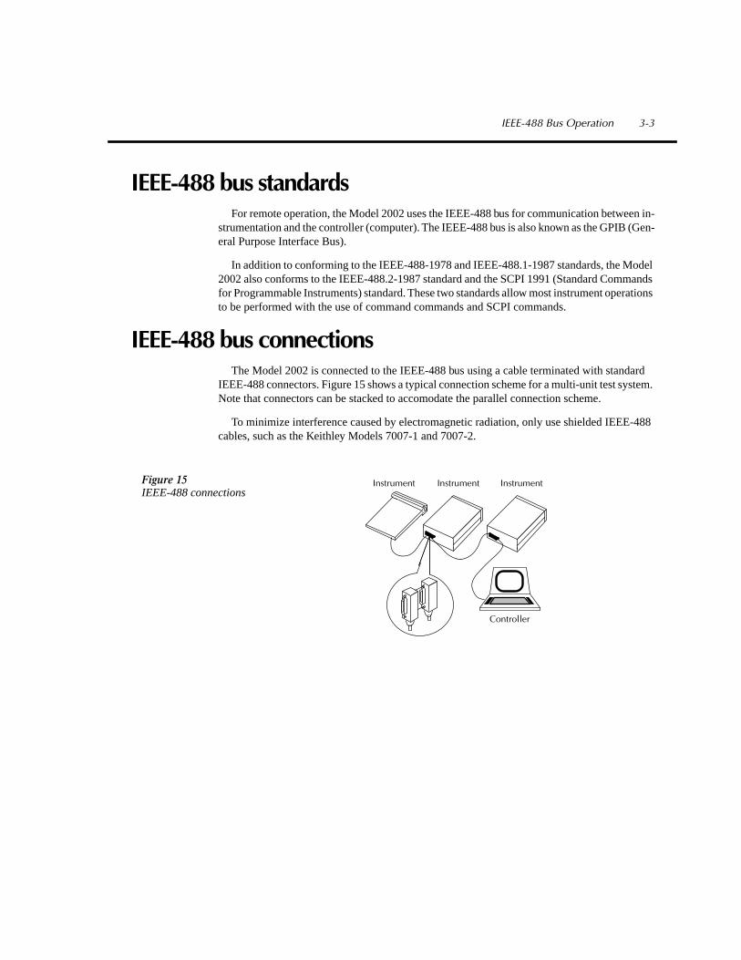
IEEE-488 bus connections
The Model 2002 is connected to the IEEE-488 bus using a cable terminated with standard IEEE-488 connectors. Figure 15 shows a typical connection scheme for a multi-unit test system. Note that connectors can be stacked to accomodate the parallel connection scheme.
To minimize interference caused by electromagnetic radiation, only use shielded IEEE-488 cables, such as the Keithley Models 7007-1 and 7007-2.
Instrument
Controller
Instrument InstrumentFigure 15IEEE-488 connections
IEEE-488 Bus Operation 3-3

Primary address selection
The Model 2002 is shipped from the factory with a programmed primary address of 16. The address is displayed on power-up. Programming examples in this manual assume a primary ad-dress of 16.
Perform the following steps to check and/or change the primary address:
1. Press MENU to display the MAIN MENU.2. Place the cursor on GPIB and press ENTER to display the GPIB/PRINT SETUP op-
tions.3. Place the cursor on ADDRESSABLE and press ENTER to display the primary address.4. To change the address, use the cursor keys and the range keys to display the desired ad-
dress and, press ENTER.
NOTE
Each device on the bus must have a unique address. Typically, the computer uses ad-dress 0 or 21.
5. Use the EXIT key to back out of the menu structure.
3-4 IEEE-488 Bus Operation

Common commands
Common commands are common to all IEEE-488 devices on the bus. The following infor-mation summarizes the Common commands that are used most often. For complete details, refer to Section 3 in the User’s Manual.
*CLS
(clear status)
Clears all event registers and Error Queue. After clearing an event register, you can monitor the register for a bit to set, indicating that an event (such as the buffer becoming full) has oc-curred.
*SAV <NRf>
(save)
Saves the instrument setup to the specified memory location (0 to 9). The number of available memory locations depends on the memory option that is installed. With no extended memory, only location 0 is valid. With MEM1, locations 0 to 4 are valid. With MEM2, locations 0 to 9 are valid. Example: To save the setup to memory location 0, send
*SAV 0
.
*RCL <NRf>
(recall)
Returns the instrument to the instrument setup saved at the specified memory location. Ex-ample: To recall the setup saved at memory location 0, send
*RCL 0
.
*TRG
(trigger)
When a trigger model control source is set for BUS, event detection is satisfied by sending this bus trigger. For example, if instrument operation is waiting at the measure (trigger) layer control source and it is programmed for BUS events,
*TRG
will provide the required event result-ing in a device action (measurement).
*WAI
(wait to continue)
This delay is used to allow the
*TRG
or an initiate command (
:INIT
or
:INIT:CONT ON
) to fin-ish before processing any further commands. An
INITiate
command is not considered finished until instrument operation returns to the idle state.
IEEE-488 Bus Operation 3-5

SCPI commands
In the Model 2002 Multimeter, you are given access to control settings that are hidden on oth-er instruments. The increased capability does, however, produce increased complexity. To ac-commodate this, the multimeter incorporates the Standard Commands for Programmable Instruments (SCPI) command set.
Because the instrument has more control points available, it requires more commands than its counterparts to perform comparable tasks. Also, since the command set is much larger than that of other instruments, finding the right commands to do the job is more difficult. Finally, SCPI command names are longer than command names in other instruments.
This introduction to the SCPI command set has three goals:
• Describe the syntax of SCPI commands. Included are descriptions of short forms and de-fault nodes, which help reduce the amount of data sent to the instrument.
• Provide some simple programs to perform commonly used tasks.• Describe the SCPI commands used in the example programs so you can modify the
programs to suit your needs.
3-6 IEEE-488 Bus Operation

SCPI command syntax
Tree structure
SCPI commands are organized in a tree structure, similar to disk directories in computer op-erating systems. Each subdirectory is called a subsystem. For example, part of the
SENSe1
sub-system is listed below and shown in Figure 16.
[SENSe[1]]:DATA?:FUNCtion "<name>":VOLTage
:DC:RANGE
[:UPPer] <n>:AUTO <Boolean> | ONCE
:REFerence <n>:STATe <Boolean>:ACQuire
Figure 16Hierarchy of the example SENSe1 commands
SENSe1
:DATA? :FUNCtion :VOLTage
:DC
:RANGe :REFerence
[:UPPer] :AUTO :STATe :ACQuire
IEEE-488 Bus Operation 3-7

A command summary table is a way of documenting SCPI commands, but it does not show complete command names. A complete command is formed by joining the components. For ex-ample, the complete
:STATe
command in the example is:
SENSe1:VOLTage:DC:REFerence:STATe
Note that square brackets are not part of the command; they indicate optional parts of the command.
This hierarchical approach permits the same command to be used many times. For example, many subsystems contain a
:STATe
command, but each one is unique because the complete command is unique. This is analogous to having a file named INDEX.TXT, for example, in each directory of your computer's hard disk. Although the files have the same name, they are unique because they are each in a different directory.
Long and short form commands
Every SCPI command has a short form, and most also have a long form. The notation used in documentation shows the short form in upper case, with the remainder of the name, which creates the long form, shown in lower case. There are no intermediate forms of the command name - you must send the exact short or long form. However, you do not have to use the mixed capitalization - the Model 2002 accepts commands in any combination of upper and lower case. For example, all of the following are valid forms of the
SENSe1:VOLTage:DC:REFerence
com-mand:
sense1:voltage:dc:reference:statesens1:volt:dc:ref:statSENS1:volt:DC:rEFErENCe:STat
3-8 IEEE-488 Bus Operation

Query commands
With few exceptions, every SCPI command has a corresponding query. A command sets a control point in the instrument; a query determines the present setting of the control point. The query is simply the command name with a "?" attached.
Some commands are actions rather than control point settings. These commands have no que-ry form. For example,
SENSe1:VOLTage:DC:REFerence:ACQuire
is an action command, not a setting, and so has no query form.
There are some queries that have no corresponding command. For example,
SENSe1:DATA?
causes the instrument to return the latest reading. Of course, there is no corresponding command to send a reading value into the instrument.
Default nodes
SCPI uses the concept of default nodes. Consider the example command tree shown previ-ously in Figure 16. What is within square brackets is not necessary to send to the instrument, but the instrument will accept it if you send it. Consider the
:UPPer
command, which sets the mea-surement range. To set the Mode 2002 to measure 15VDC, any of the following commands works:
SENSe1:VOLTage:DC:RANGe:UPPer 15SENSe:VOLTage:DC:RANGe:UPPer 15SENSe1:VOLTage:DC:RANGe 15VOLTage:DC:RANGe:UPPer 15VOLTage:DC:RANGe 15
These are shown in long form, but short forms could also be used.
IEEE-488 Bus Operation 3-9

Command syntax
Notice in the preceding examples that there is no colon character at the beginning of the com-mands. A leading colon instructs the Model 2002 to interpret the command starting at the root (highest level) of the command tree. Since the Model 2002 also starts at the root each time you send it a new command, the leading colon is not needed (although the instrument will accept it if you send it).
You can send multiple commands in a single message. You separate the commands with a semicolon character. When the Model 2002 encounters a command following a semicolon, it at-tempts to interpret the command starting at the level of the previous command, unless you pre-cede the second command with a colon. For example, either of the following comand strings programs the Model 2002 to the 20VDC range and uses 5VDC as a relative value (with the REF-erence commands):
volt:dc:rang 20;ref 5;ref:stat onvolt:dc:rang 20;:volt:dc:ref 5;:volt:dc:ref:stat on
The two command strings are treated identically by the Model 2002. In the first string when the instrument encounter
";ref 5"
, it notices the following:
• It is not the first command in the string.• There is no leading colon on the command.• The previous command was at the
VOLTage:DC
level.
Therefore, it interprets the command as if it were at the
VOLTage:DC
level.
3-10 IEEE-488 Bus Operation

SCPI signal oriented commands
Signal oriented commands are used to acquire readings using a set of high-level instructions to control the measurement process. The two most commonly used commands are
:FETCh?
and
:MEASure?
. Details on all signal oriented commands are covered in Section 3 in the User’s Man-ual.
:FETCh?
This query command is used to request the latest post-processed reading. After sending this command and addressing the Model 2002 to talk, the reading will be sent to the computer. This command does not trigger a measurement, it simply requests the last available reading.
:MEASure[:<function>]?
In general, this command places the instrument in the “one-shot” measurement mode (ARM indicator off), triggers a single measurement, and then performs a
:FETCh?
.
If you include the measurement function with this command, the instrument will first go to the specified function and then perform the one-shot measurement and query, as follows:
:MEASure?
Currently selected function
:MEASure:VOLTage:DC?
DCV function
:MEASure:VOLTage:AC?
ACV function
:MEASure:CURRent:DC?
DCI function
:MEASure:CURRent:AC?
ACI function
:MEASure:RESistance?
Ω
2 function
:MEASure:FRESistance?
Ω
4 function
:MEASure:FREQuency?
FREQ function
:MEASure:TEMPerature?
TEMP function
IEEE-488 Bus Operation 3-11

SCPI subsystem commands
Detailed information an all SCPI commands are covered in the User’s Manual. In this section, only the command used for basic operation are summarized.
Defaults
:SYSTem
SYSTem Subsystem
:PREset
Set the 2002 to the system present defaults.Some of the selected defaults include: DCV, continu-ous triggers, normal speed (1.0 PLC), auto range and auto filter.
:POSetup <name>
Select power-on setups:
RST
, PRESet or SAV0 through SAV9. Instrument will power up to the *RST or system present defaults, or one of the *SAV0 – *SAV9 setups.
Fresh readings[:SENSe[1]] SENSe Subsystem
:DATA:FRESh? Requests a “fresh” reading. This command will not re-quest the same reading twice. If a new reading has al-ready been triggered, this command will wait until the new reading is available.
:CALCulate[1] CALCulate Subsystem:DATA:FRESh? Requests a “fresh” calculated reading. When CALC1
is enabled, sens:data:fres? is the reading before calcu-lation and calc:data:fres? is the reading after calcula-tion. When CALC1 is disabled, the readings are the same.
Function configuration[:SENSe[1]] SENSe Subsystem
:FUNCtion <name> Select measurement function:<name> = 'VOLTage:DC' DCV function
'VOLTage:AC' ACV function'CURRent:DC' DCI function'CURRent:AC' ACI function'RESistance' Ω2 function'FRESistance' Ω4 function'FREQuency' FREQ function'TEMPerature' TEMP function
3-12 IEEE-488 Bus Operation

:VOLTage:DC Path to configure DCV::NPLC <n> Set speed: 0.01 to 10 PLC.
:AUTO <b> Enable or disable auto NPLC.:RANGe Path to configure measurement range:
[:UPPer] <n> Specify expected reading to select range.:AUTO <n> Enable or disable auto range.
:REFerence <n> Specify reference (rel): -1100 to +1100.:STATe <b> Enable or disable reference (rel).:ACQuire Use input signal as reference (rel).
:DIGits <n> Specify measurement resolution (see note 1).:AUTO <b> Enable or disable auto resolution.
:AVERage Path to control the filter (see note 2).[:STATe] <b> Enable or disable the filter.:TCONtrol <name> Select filter type (MOVing or REPeat).:COUNt <n> Specify the filter count (1 to 100).:AUTO <b> Enable or disable auto filter.
:VOLTage:AC Path to configure ACV:(DCV commands) The commands listed to configure DCV apply.:COUPling <name> Specify input coupling: AC or DC.:DETector Path to select AC type:
[:FUNCtion] <name> Select AC type: RMS, AVERage, PEAK, LFRMs, NPEak or PPEak.
:PWINdow <n> Specify window in seconds (0.1 to 9.9) for NPEak or PPEak
:CURRent:DC Path to configure DCI:(DCV commands) The commands listed to configure DCV apply.:METHod <name> Select measure technique: NORMal, ICIRcuit .
:CURRent:AC Path to configure ACI:(DCV commands) The commands listed to configure DCV apply.:COUPling <name> Specify input coupling: AC or DC.:DETector Path to select AC type:
[:FUNCtion] <name> Select AC type: RMS or AVERage.
:RESistance Path to configure Ω2:(DCV commands) The commands listed to configure DCV apply.:OCOMpensated <b> Enable or disable offset compensation.
:FRESistance Path to configure Ω4:(DCV commands) The commands listed to configure DCV apply.:OCOMpensated <b> Enable or disable offset compensation.
IEEE-488 Bus Operation 3-13

:FREQuency Path to configure FREQ::COUPling <name> Specify input coupling: AC or DC.:REFerence <n> Specify reference (rel): 0 to 15e6.
:STATe <b> Enable or disable reference (rel).:ACQuire Use input signal as reference (rel).
:DIGits <n> Specify measurement resolution: 4 or 5.:SOURce <name> Select source: CURRent or VOLTage.:THReshold Path to configure threshold:
:CURRent Path to set current threshold::RANGe <n> Specify range: 0 to 1.:LEVel <n> Specify level: ±60% of max signal level.
:VOLTage Path to configure voltage threshold::RANGe <n> Specify range: 0 to 1000.:LEVel <n> Specify level: ±60% of max signal level.:TTL Set threshold to TTL level.
:TEMPerature Path to configure TEMP (RTD):(DCV commands) DCV commands (except :RANGe) apply.:TRANsducer <name> Select transducer: RTD, FRTD or TCouple .:RTD Path to configure RTD measurements:
:TYPE <name> Select parameters: PT385, PT3916, PT100, D100 F100, or USER.
:ALPHa <NRf> Specify alpha constant for USER: 0 to 0.01.:BETA <NRf> Specify beta constant for USER: 0 to 1.:DELTa <NRf> Specify delta constant for USER: 0 to 5.:RZERo <NRf> Specify rzero constant for USER: 0 to 1000.
Notes:
1. Resolution (:DIGits ) parameters:
All functions except FREQ and TEMP — 3.5 to 8.5.
FREQ— 4 to 5.
TEMP — 4 to 7.
2. An advanced filter is available for DCV, ACV, DCI, ACI, Ω2, and Ω4. Refer to the User’s Manual to use the advanced filter.
3-14 IEEE-488 Bus Operation

Measurement units (ACV and TEMP):UNIT UNIT Subsystem
:TEMPerature <name> Select units for TEMP: C, F, or K.:VOLTage Path to configure units for ACV:
:AC <name> Select units for ACV: V, DB, or DBM.:DB Path to set dB reference voltage:
:REFerence <n> Specify reference (volts): 0.001 to 750.:DBM Path to set dBm reference impedance:
:IMPedance <n> Specify reference (Ω): 1 to 9999.
Data store (Buffer):TRACe TRACe Subsystem
:EGRoup <name> Select element group: FULL or COMPact.:POINts <n> Specify buffer size.:FEED <name> Select reading source: SENSe, CALCulate or NONE.
:CONTrol <name> Select control mode and enable buffer: NEVer, NEXT, ALWays or PRETrigger .
Note: See User’s Manual to use :PRETrigger .
Open/close channels and scan:ROUTe ROUTe Subsystem
:CLOSe <list> Close specified channel.:STATe? Query the closed channel.
:OPEN <list> Open specified channel.:OPEN:ALL Open all channels.:SCAN Path to control scanning (see note):
[:INTernal] <list> Specify internal scan list: 2 to 10 chans.:EXTernal <list> Specify external scan list: 2 to 80 chans.:LSELect <name> Enable the specified scan: INTernal , EXTernal , RA-
Tio , DELTa or NONE (see note).
Note: See User’s Manual to use :RATio and :DELTa .
IEEE-488 Bus Operation 3-15

Trigger modelPerforming a system preset (:SYSTem:PRESet) configures the trigger model for typical in-
strument operation. After a system preset, many advanced operations can be accomplished using the initiate commands, :ABORt, and the trigger (measure) layer commands. All of the following commands are part of the Trigger Subsystem.
:INITiate[:IMMediate] Take the instrument out of idle (ARM indicator on).:CONTinuous <b> Enable or disable continuous initiation.
:ABORt Reset trigger system. Instrument stays in idle if continu-ous initiation is disabled (off).
:TRIGger Path to configure the trigger layer::SOURce <name> Select control source: IMMediate , TIMer , MANual, BUS,
TLINk , EXTernal or HOLD.:TIMer <n> Set timer interval (sec): 0 to 9999999.999.:DELay <n> Set delay between measurements (sec) 0 to
999999.999.
3-16 IEEE-488 Bus Operation

Status registerThe status register structure of the Model 2002 lets you monitor and act upon numerous
events that occur. Many programming decisions can be made by monitoring the Measurement Event Register and the Operation Event Register. See the User’s Manual for details of the status registers.
:STATus STATus Subsystem.:MEASurement Path for measurement status registers:
:[:EVENt]? Use to read the Measurement Event Register.:OPERation Path for operation status registers:
[:EVENt]? Use to read the Operation Event Register.
When an event register is read, a decimal value is sent to the computer. The binary equivalent determines which bits in the register are set. For example, a decimal value of 33 indicates that bits B0 and B5 are set. An event register is cleared when it is read. Sending *CLS clears all event registers.
Some of the more useful bits of these event registers are summarized as follows:
Measurement Event Register Operation Event Register
Bit B0 set = Reading Overflow Bit B4 set = MeasuringBit B5 set = Reading Available Bit B9 set = CalculatingBit B7 set = Buffer Available Bit B10 set = IdleBit B8 set = Buffer Half FullBit B9 set = Buffer Full
IEEE-488 Bus Operation 3-17

Program examplesAll examples presume QuickBASIC version 4.5 or higher and a CEC IEEE-488 interface
card with CEC driver version 2.11 or higher, with the Model 2002 at address 16 on the IEEE-488 bus.
Changing function and rangeThe Model 2002 has independent controls for each of its measurement functions. This means,
for example, that autorange can be turned on for DC voltage while leaving it off for AC voltage.
Another difference is in the parameter to the range command. In our older instruments, a sin-gle number was used to denote each range. The parameter of the SCPI RANGe command is given as "the maximum value to measure." The instrument interprets this parameter and goes to the appropriate range. When you query the range with RANGe? the instrument sends back the full-scale value of its present range.
The following example program illustrates changing function and range. It sets the range for several functions, then takes readings on each of those functions.
Note that the Model 2002 rounds the range parameter to an integer before choosing the ap-propriate range. Sending VOLTage:DC:RANGe 20.45 will set the Model 2002 to the 20V range.
3-18 IEEE-488 Bus Operation

'Example program to demonstrate changing function and range,'taking readings on various functions'For QuickBASIC 4.5 and CEC PC488 interface card
'Edit the following line to where the QuickBASIC'libraries are on your computer'$INCLUDE: 'c:\qb45\ieeeqb.bi'
'Initialize the CEC interface as address 21CALL initialize(21, 0)
'Reset the SENSe1 subsystem settings, along with the trigger'model, each READ? will cause one triggerCALL SEND(16, "*rst", status%)
'Set range for each function to measureCALL SEND(16, "volt:dc:rang .1", status%)CALL SEND(16, "volt:ac:rang 20", status%)CALL SEND(16, "res:rang 10e3", status%)
'Switch to DC volts and take readingCALL SEND(16, "func 'volt:dc';:read?", status%)reading$ = SPACE$(80)CALL ENTER(reading$, length%, 16, status%)PRINT reading$
'Switch to AC volts and take readingCALL SEND(16, "func 'volt:ac';:read?", status%)reading$ = SPACE$(80)CALL ENTER(reading$, length%, 16, status%)PRINT reading$
'Switch to 2-wire ohms and take readingCALL SEND(16, "func 'res';:read?", status%)reading$ = SPACE$(80)CALL ENTER(reading$, length%, 16, status%)PRINT reading$
IEEE-488 Bus Operation 3-19
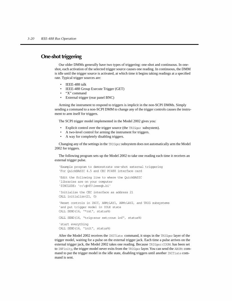
One-shot triggeringOur older DMMs generally have two types of triggering: one-shot and continuous. In one-
shot, each activation of the selected trigger source causes one reading. In continuous, the DMM is idle until the trigger source is activated, at which time it begins taking readings at a specified rate. Typical trigger sources are:
• IEEE-488 talk• IEEE-488 Group Execute Trigger (GET)• “X” command• External trigger (rear panel BNC)
Arming the instrument to respond to triggers is implicit in the non-SCPI DMMs. Simply sending a command to a non-SCPI DMM to change any of the trigger controls causes the instru-ment to arm itself for triggers.
The SCPI trigger model implemented in the Model 2002 gives you:
• Explicit control over the trigger source (the TRIGger subsystem).• A two-level control for arming the instrument for triggers.• A way for completely disabling triggers.
Changing any of the settings in the TRIGger subsystem does not automatically arm the Model 2002 for triggers.
The following program sets up the Model 2002 to take one reading each time it receives an external trigger pulse.
'Example program to demonstrate one-shot external triggering'For QuickBASIC 4.5 and CEC PC488 interface card
'Edit the following line to where the QuickBASIC'libraries are on your computer'$INCLUDE: 'c:\qb45\ieeeqb.bi'
'Initialize the CEC interface as address 21CALL initialize(21, 0)
'Reset controls in INIT, ARM;LAY1, ARM:LAY2, and TRIG subsystems'and put trigger model in IDLE stateCALL SEND(16, "*rst", status%)
CALL SEND(16, "trig:sour ext;coun inf", status%)
'start everythingCALL SEND(16, "init", status%)
After the Model 2002 receives the INITiate command, it stops in the TRIGger layer of the trigger model, waiting for a pulse on the external trigger jack. Each time a pulse arrives on the external trigger jack, the Model 2002 takes one reading. Because TRIGger:COUNt has been set to INFinity , the trigger model never exits from the TRIGger layer. You can send the ABORt com-mand to put the trigger model in the idle state, disabling triggers until another INITiate com-mand is sent.
3-20 IEEE-488 Bus Operation

Continuous triggering #1The following example program sets up the Model 2002 to take readings as fast as it can once
it receives an external trigger. The actual reading rate will depend upon other factors, such as A/D integration time, autozero mode, autorange on/off, etc.
'Example program to demonstrate continuous triggering'For QuickBASIC 4.5 and CEC PC488 interface card
'Edit the following line to where the QuickBASIC'libraries are on your computer'$INCLUDE: 'c:\qb45\ieeeqb.bi'
'Initialize the CEC interface as address 21CALL initialize(21, 0)
'Reset controls in INIT, ARM;LAY1, ARM:LAY2, and TRIG subsystems'and put trigger model in IDLE stateCALL SEND(16, "*rst", status%)
'*RST sets TRIG:SOUR to IMMCALL SEND(16, "arm:lay2:sour ext", status%)CALL SEND(16, "trig:coun inf", status%)
'start everythingCALL SEND(16, "init", status%)
After the Model 2002 receives the INITiate command, it stops in ARM:LAYer2 of the trigger model, waiting for a pulse on the external trigger jack. After the external trigger signal occurs, the Model 2002 moves to the TRIGger layer. Since TRIGger:SOURce is set to IMMediate , a read-ing is triggered immediately, with a subsequent reading triggered as soon as the previous one is finished.
IEEE-488 Bus Operation 3-21

Continuous triggering #2The following example program sets up the Model 2002 to take readings continuously after
an external trigger is received. The trigger rate is set to one reading every 50ms.
'Example program to demonstrate continuous triggering'at a specified rate'For QuickBASIC 4.5 and CEC PC488 interface card
'Edit the following line to where the QuickBASIC'libraries are on your computer'$INCLUDE: 'c:\qb45\ieeeqb.bi'
'Initialize the CEC interface as address 21CALL initialize(21, 0)
'Reset controls in INIT, ARM;LAY1, ARM:LAY2, and TRIG subsystems'and put trigger model in IDLE stateCALL SEND(16, "*rst", status%)
'*RST sets TRIG:SOUR to IMMCALL SEND(16, "arm:lay2:sour ext", status%)CALL SEND(16, "trig:coun inf;sour tim;tim .05", status%)
'start everythingCALL SEND(16, "init", status%)
After the Model 2002 receives the INITiate command, it stops in ARM:LAYer2 of the trigger model, waiting for a pulse on the external trigger jack. After the external trigger signal occurs, the Model 2002 moves to the TRIGger layer. Since TRIGger:SOURce is set to TIMer , a reading is triggered immediately, with a subsequent reading every 50ms. Because TRIGger:COUNt has been set to infinity, the trigger model never exits from the TRIGger layer.
3-22 IEEE-488 Bus Operation

Generating SRQ on buffer fullWhen your program must wait until the Model 2002 has completed an operation, it is more
efficient to program the 2002 to assert the IEEE-488 SRQ line when it is finished, rather than repeatedly serial polling the instrument. An IEEE-488 controller will typically address the in-strument to talk, then unaddress it, each time it performs a serial poll. Repeated polling of the Model 2002 will generally reduce its overall reading throughput. Therefore, use the srq%() function call.
The Model 2002 provides a status bit for nearly every operation it performs. It can be pro-grammed to assert the IEEE-488 SRQ line whenever a status bit becomes true or false. The IEEE-488 controller (your computer) can examine the state of the the SRQ line without per-forming a serial poll, thereby detecting when the 2002 has completed its task without interrupt-ing it in the process.
The following example program segment sets up the Model 2002 to assert SRQ when the reading buffer has completely filled, then arms the reading buffer, initiates readings, and waits for the Model 2002 to indicate that the buffer is full.
This is not a complete program. Not shown are the commands to configure the trigger model and the reading buffer (see the next example). The example shown here can be modified for any event in the Model 2002 status reporting system.
'Reset STATus subsystem (not affected by *RST)CALL SEND(16, "stat:pres;*cls", status%)
CALL SEND(16, "stat:meas:enab 512", status%)'enable BFLCALL SEND(16, "*sre 1"' status%)'enable MSBCALL SEND(16, "trac:feed:cont next", status%)
' Start everythingCALL SEND(16, "init", status%)
WaitSRQ:IF (NOT(srq%()) THEN GOTO WaitSRQCALL SPOLL(16, poll%, status%)IF (poll% AND 64)=0 THEN GOTO WaitSRQ
Notice that after the program has detected an asserted SRQ line, it serial polls the Model 2002 to determine if it is the device requesting service. This is necessary for two reasons:
• Serial polling the Model 2002 causes it to quit asserting the SRQ line.• In test systems that have more than one IEEE-488 instrument programmed to assert
SRQ, your program must determine which instrument is actually requesting service.
Once an event register has caused a service request, it cannot cause another service request until you clear it by reading it (in this case using STATus:MEASurement[:EVENt]? ) or by sending the *CLS command.
IEEE-488 Bus Operation 3-23

Storing readings in bufferThe reading buffer in the Model 2002 is flexible and capable. It has four controls, which are
found in the TRACe susbsystem. There are commands to control:
• The size of the buffer (in readings).TRACe:POINts <NRf>
• Whether or not extra data is stored with each reading (e.g., channel number, timestamp). Storing extra data reduces the maximum size of the buffer.TRACe:EGRoup FULL include extra dataTRACe:EGRoup COMPact exclude extra data
• Where the data is coming from (before or after the CALCulate1 math post-processing).TRACe:FEED SENSe1 store unprocessed readingsTRACe:FEED CALCualte1 store math processed readings
• Select buffer control mode.TRACe:FEED:CONTrol NEVer immediately stop storing readingsTRACe:FEED:CONTrol NEXT start now, stop when buffer is fullTRACe:FEED:CONTrol ALWays start now, never stopTRACe:FEED:CONTrol PRETrigger start now, stop when pretrigger is satisfied
The following example program sets up the Model 2002 to take 20 readings as fast as it can into the buffer, then reads the data back after the buffer has filled. The readings will be stored with the timestamp, etc., but the program reads back only the reading values and timestamp.
3-24 IEEE-488 Bus Operation

'Example program to demonstrate the reading buffer'For QuickBASIC 4.5 and CEC PC488 interface card
'Edit the following line to where the QuickBASIC'libraries are on your computer'$INCLUDE: 'c:\qb45\ieeeqb.bi'
'Initialize the CEC interface as address 21CALL initialize(21, 0)
'Reset controls in INIT, ARM;LAY1, ARM:LAY2, and TRIG subsystems'and put trigger model in IDLE stateCALL SEND(16, "*rst", status%)
'Reset STATus subsystem (not affected by *RST)CALL SEND(16, "stat:pres;*cls", status%)CALL SEND(16, "stat:meas:enab 512", status%)'enable BFLCALL SEND(16, "*sre 1", status%)'enable MSBCALL SEND(16, "trig:coun 20", status%)
'TRACe subsystem is not affected by *RSTCALL SEND(16, "trac:poin 20;egr full", status%)CALL SEND(16, "trac:feed sens1;feed:cont next", status%)
'Start everythingCALL SEND(16, "init", status%)
'Initialize reading$ while the 2002 is busy taking readingsreading$ = SPACE$(4000)
WaitSRQ:IF (NOT(srq%) THEN GOTO WaitSRQCALL SPOLL(16, poll%, status%)IF (poll% AND 64)=0 THEN GOTO WaitSRQ
CALL SEND(16, "form:elem read,time", status%)CALL SEND(16, "trac:data?", status%)CALL ENTER(reading$, length%, 16, status%)PRINT reading$
IEEE-488 Bus Operation 3-25

Taking readings with the scanner cardThe Model 2001-SCAN is an optional 10-channel scanner card for the Model 2002 Multim-
eter. Only one channel can be closed at a time. If you close a channel while another is already closed, the first one opens with break-before-make operation.
You can use the scanner card two ways. One is to issue a command to close a particular chan-nel before sending other commands to take readings. The other way is to program the scan list, and let the meter take care of closing a channel before taking a reading. There is a fundamental difference in the instrument's behavior in these two approaches.
In the scan list, a measurement function is bound to each channel, so that when the next chan-nel in the list closes, the meter switches to the associated function. Simply sending a channel close command, however, does not change the measurement function. While using the scan list, the meter responds to a trigger by first going to the next channel in the list, then switching to the function bound to that channel, before taking a reading.
The following example program measures DC volts on channel 1, AC volts on channel 2, and 2-wire resistance on channel 3, using the ROUTe:CLOSe command.
3-26 IEEE-488 Bus Operation

'Example program to demonstrate taking readings on different'scanner channels'For QuickBASIC 4.5 and CEC PC488 interface card
'Edit the following line to where the QuickBASIC'libraries are on your computer'$INCLUDE: 'c:\qb45\ieeeqb.bi'
'Initialize the CEC interface as address 21CALL initialize(21, 0)
'Reset controls in INIT, ARM;LAY1, ARM:LAY2, and TRIG subsystems'and put trigger model in IDLE state, set function to DCVCALL SEND(16, "*rst", status%)
'Close channel 1, take DC voltage readingCALL SEND(16, "rout:clos (@1);:read?", status%)reading$ = SPACE$(80)CALL ENTER(reading$, length%, 16, status%)PRINT reading$
'Close channel 2, take AC voltage readingCALL SEND(16, "func 'volts:ac'", status%)CALL SEND(16, "rout:clos (@2);:read?", status%)reading$ = SPACE$(80)CALL ENTER(reading$, length%, 16, status%)PRINT reading$
'Close channel 3, take ohms readingCALL SEND(16, "func 'res'", status%)CALL SEND(16, "rout:clos (@3);:read?", status%)reading$ = SPACE$(80)CALL ENTER(reading$, length%, 16, status%)PRINT reading$
IEEE-488 Bus Operation 3-27

The following example program sets up the Model 2002 using a scan list to measure DC volt-age on channel 1, AC voltage on channel 2, and 2-wire resistance on channel 3. The meter takes ten sets of readings, with each set spaced 15 seconds apart, and each of the three readings in each group taken as fast as possible. The Model 2002 stores the readings in the buffer, and asserts SRQ when the buffer is full. The program waits for the SRQ, then reads the readings from the buffer.
'Example program to demonstrate using the scan list'For QuickBASIC 4.5 and CEC PC488 interface card
'Edit the following line to where the QuickBASIC'libraries are on your computer'$INCLUDE: 'c:\qb45\ieeeqb.bi'
'Initialize the CEC interface as address 21CALL initialize(21, 0)
'Reset controls in INIT, ARM;LAY1, ARM:LAY2, and TRIG subsystems'and put trigger model in IDLE state, set function to DCVCALL SEND(16, "*rst", status%)
'Reset STATus subsystem (not affected by *RST)CALL SEND(16, "stat:pres;*cls", status%)
CALL SEND(16, "stat:meas:enab 512", status%)'enable BFLCALL SEND(16, "*sre 1", status%)'enable MSB
3-28 IEEE-488 Bus Operation

'*RST sets TRIG:SOUR to IMMCALL SEND(16, "trig:coun 3", status%)CALL SEND(16, "arm:lay2:sour tim;tim 15", status%)CALL SEND(16, "arm:lay2:coun 10", status%)
'TRACe subsystem is not affected by *RSTCALL SEND(16, "trac:poin 30;egr full", status%)CALL SEND(16, "trac:feed sens1;feed:coun next", status%)' now the buffer is armed
CALL SEND(16, "rout:scan (@1:3)", status%)CALL SEND(16, "rout:scan:func (@1), 'volt:dc'", status%)CALL SEND(16, "rout:scan:func (@2), 'volt:ac'", status%)CALL SEND(16, "rout:scan:func (@3), 'res'", status%)CALL SEND(16, "rout:lsel int", status%)
'Start everythingCALL SEND(16, "init", status%)
'Initialize reading$ while the 2002 is busy taking readingsreading$ = SPACE$(2500)
WaitSRQ:IF (NOT(srq%()) THEN GOTO WaitSRQCALL SPOLL(16, poll%, status%)IF (poll% AND 64)=0 THEN GOTO WaitSRQ
CALL SEND(16, "form:elem read,time,chan", status%)CALL SEND(16, "trac:data?, status%)CALL ENTER(reading$, length%, 16, status%)PRINT reading$
IEEE-488 Bus Operation 3-29

4
Specs andAccessories
Specifications
The following pages contain the condensed specifications for the 2002. Every effort has been made to make these specifications complete by characterizing its performance under the variety of conditions often encountered in production, engineering, and research.
The 2002 provides transfer, 24-hour, 90-day, 1-year, and 2-year specifications, with full spec-ifications for the 90-day, 1-year, and 2-year intervals. This allows the operator to utilize 90-day, 1-year, or 2-year recommended calibration intervals, depending upon the level of accuracy de-sired. As a general rule, the 2002’s 2-year performance exceeds a 6
½
-digit DMM’s 90-day, 180-day, or 1-year specifications.
Absolute accuracy
All DC specifications are given as relative accuracies. To obtain absolute accuracies, the ab-solute uncertainties of the calibration sources must be added to the relative accuracies. The ab-solute uncertainties for the calibration sources used during Keithley’s factory calibration are included in the specifications. The uncertainties of the operator’s sources may be different.
All AC specifications are given as absolute accuracies.
Typical accuracies
Accuracy can be specified as typical or warranted. All specifications shown are warranted un-less specifically noted. Almost 99% of the 2002’s specifications are warranted specifications. In some cases it is not possible to obtain sources to maintain traceability on the performance of ev-ery unit in production on some measurements (e.g., high-voltage, high-frequency signal sources with sufficient accuracy do not exist). These values are listed as typical.
4-2 Specs and Accessories

DC VOLTS
DCV INPUT CHARACTERISTICS AND ACCURACY
ENHANCED ACCURACY
1
- 10PLC, DFILT 10RELATIVE ACCURACY TEMP.
FULL RESO- INPUT ±(ppm of reading + ppm of range) COEFFI-RANGE SCALE LUTION RESISTANCE Transfer
5
24 Hours
2
90 Days
3
1 Year
3
2 Years
3
CIENT*
200 mV
4
±210.000000 1 nV >100 G
Ω
0.4 + 1.5 3.5 + 3 15 + 8 19 + 9 23 + 10 2 + 1.82 V
4
±2.10000000 10 nV >100 G
Ω
0.2 + 0.15 1.2 + 0.3 6 + 0.8 10 + 0.9 14 + 1 0.2 + 0.1820 V ±21.0000000 100 nV >100 G
Ω
0.1 + 0.05 1.2 + 0.1 6 + 0.15 10 + 0.15 14 + 0.15 0.3 + 0.02200 V ±210.000000 1 µV 10 M
Ω
±1% 0.5 + 0.08 5 + 0.4 14 + 2 22 + 2 30 + 2 1.5 + 0.31000 V
6
±1100.00000 10 µV 10 M
Ω
±1% 1 + 0.05 5 + 0.08 14 + 0.4 22 + 0.4 30 + 0.4 1.5 + 0.06
* ± (ppm of reading + ppm of range)/°C Outside T
CAL
± 5°C1. Specifications are for 10 power line cycles, synchronous autozero, 10-reading repeat digital filter, autorange off, except as noted.2. For TCAL ±1°C, following 4-hour warm-up. TCAL is ambient temperature at calibration (23°C at the factory). Add 0.5 ppm of reading
uncertainty if the unit is power cycled during this interval.3. For TCAL ±5°C, following 4-hour warm-up. 4. Care must be taken to minimize thermal offsets due to operator cables.5. Specifications apply for 20-reading repeat digital filter, TREF ± 0.5°C (TREF is the initial ambient temperature), and for measurements with-
in 10% of the initial measurement value and within 10 minutes of the initial measurement time.6. Add 2.5ppm
×
(V
IN
/1000V)
2
additional uncertainty for inputs above 200V, except in transfer accuracy specifications.
DC VOLTAGE UNCERTAINTY
= ± [ (ppm of reading)
×
(measured value) + (ppm of range)
×
(range used) ] / 1,000,000.
% ACCURACY
= (ppm accuracy) /10,000.
1PPM OF RANGE
= 20 counts for ranges up to 200V and 10 counts on 1000V range at 7
½
digits.
KEITHLEY FACTORY CALIBRATION UNCERTAINTY
RANGE ppm of reading
200 mV 3.22 V 3.2
20 V 2.6200 V 2.6
1000 V 2.6
AC VOLTS
NORMAL MODE RMS
1
90 Days, 1 Year or 2 Years, ±2°C from last AC self-cal for 1% to 100% of range
2
, ±(% of reading + % of range)100– 0.2–
RANGE 20–50Hz 50–100Hz 0.1–2kHz 2–10kHz 10–30kHz 30–50kHz 50–100kHz 200kHz 1MHz 1–2MHz
200 mV 0.25+0.015 0.07+0.015 0.02 + 0.01 0.02 + 0.01 0.025 + 0.01 0.05 + 0.01 0.17+0.015 0.5+0.025 2+0.1 5+0.22 V 0.25+0.015 0.07+0.015 0.02 + 0.01 0.02 + 0.01 0.025 + 0.01 0.05 + 0.01 0.17+0.015 0.5+0.025 2+0.1 5+0.2
20 V 0.25+0.015 0.07+0.015 0.03+0.015 0.04+0.015 0.05 +0.015 0.07+0.015 0.17+0.015 0.5+0.025 4+0.2 7+0.2
4
200 V
3
0.25+0.015 0.07+0.015 0.03+0.015 0.04+0.015 0.05 +0.015 0.07+0.015 0.17+0.015 0.5+0.025
4
4+0.2
4
750 V
3
0.25+0.015 0.1 +0.015 0.05+0.015 0.06+0.015 0.08 +0.015 0.1+0.015
4
0.5 +0.015
4
1. Specifications apply for sinewave input, AC + DC coupling, 1 power line cycle, autozero on, digital filter off, following 55-minute warm-up.2. For 1% to 5% of range below 750V range, and for 1% to 7% of 750V range, add 0.01% of range uncertainty. For inputs from 200kHz to
2MHz, specifications apply above 10% of range.3. Add 0.001% of reading
×
(V
IN
/100V)
2
additional uncertainty above 100V rms.4. Typical values.
Specs and Accessories 4-3
Factory calibration uncertainty represents traceability to NIST. This uncertainty is added to relative accuracy specifications to obtain absolute accuracies. The 200mV and 2V range uncertainties are equal to the uncertainty of the 2V calibration source. The 20V, 200V, and 1000V range uncertainties are equal to the uncertainty of the 20V calibration source.

OHMS
ENHANCED ACCURACY
1
- 10PLC, Offset comp. on, DFILT 10
TEMPERATURECOEFFICIENT
RELATIVE ACCURACY ± (ppm of reading +± (ppm of reading + ppm of range) ppm of range) / °C
RANGE Transfer
5
24 Hours
3
90 Days
4
1 Year
4
2 Years
4
Outside T
CAL
±5°C
20
Ω
2.5 + 3 5 + 4.5 15 + 6 17 + 6 20 + 6 2.5 + 0.7200
Ω
2.5 + 2 5 + 3 15 + 4 17 + 4 20 + 4 2.5 + 0.52 k
Ω
1.3 + 0.2 2.5 + 0.3 7 + 0.4 9 + 0.4 11 + 0.4 0.8 + 0.0520 k
Ω
1.3 + 0.2 2.5 + 0.3 7 + 0.4 9 + 0.4 11 + 0.4 0.8 + 0.05200 k
Ω
2.5 + 0.4 4.5 + 0.5 17 + 0.8 21 + 0.9 25 + 1 3 + 0.182 M
Ω
5 + 0.2 10 + 0.3 38 + 0.5 50 + 0.5 62 + 0.5 6 + 0.120 M
Ω
2
15 + 0.1 50 + 0.2 175 + 0.6 250 + 0.6 300 + 0.6 20 + 0.1200 M
Ω
2
50 + 0.5 150 + 1 500 + 3 550 + 3 600 + 3 80 + 0.51 G
Ω
2
250 + 2.5 750 + 5 2000 + 15 2050 + 15 2100 + 15 400 + 2.5
1. Specifications are for 10 power line cycles, 10-reading repeat digital filter, synchronous autozero, autorange off, 4-wire mode, offset com-pensation on (for 20
Ω
to 20k
Ω
ranges), except as noted.2. For 2-wire mode.3. For T
CAL
±1°C, following 4-hour warm-up. T
CAL
is ambient temperature at calibration (23°C at the factory).4. For T
CAL
±5°C, following 4-hour warm-up. 5. Specifications apply for 20-reading repeat digital filter, T
REF
± 0.5°C (T
REF
is the initial ambient temperature), and for measurements within 10% of the initial measurement value and within 10 minutes of the initial measurement time.
RESISTANCE UNCERTAINTY
= ± [ (ppm of reading)
×
(measured value) + (ppm of range)
×
(range used) ] / 1,000,000.
% ACCURACY
= (ppm accuracy) / 10,000.
1PPM OF RANGE
= 20 counts for ranges up to 200M
Ω
and 10 counts on 1G
Ω
range at 7
½
digits.
KEITHLEY FACTORY CALIBRATION UNCERTAINTY
RANGE ppm of reading
20
Ω
29.5200
Ω
7.72 k
Ω
6.420 k
Ω
7.8200 k
Ω
7.32 M
Ω
14.920 M
Ω
14.9200 M
Ω
14.91 G
Ω
14.9
DC AMPS
DCI INPUT CHARACTERISTICS AND ACCURACY
TEMPERATURECOEFFICIENT
1
MAXIMUM RELATIVE ACCURACY
1
±(ppm of reading +FULL RESO- BURDEN ±(ppm of reading + ppm of range) ppm of range)/°C
RANGE SCALE LUTION VOLTAGE
4
24 Hours
2
90 Days
3
1 Year
3
2 Years
3
Outside T
CAL
±5°C
200 µA 210.00000 10 pA 0.25 V 50 + 6 275 + 25 350 + 25 500 + 25 50 + 52 mA 2.1000000 100 pA 0.3 V 50 + 5 275 + 20 350 + 20 500 + 20 50 + 5
20 mA 21.000000 1 nA 0.35 V 50 + 5 275 + 20 350 + 20 500 + 20 50 + 5200 mA 210.00000 10 nA 0.35 V 75 + 5 300 + 20 375 + 20 525 + 20 50 + 5
2 A 2.1000000 100 nA 1.1 V 350 + 5 600 + 20 750 + 20 1000 + 20 50 + 5
1. Specifications are for 1 power line cycle, autozero on, 10-reading repeat digital filter.2. For T
CAL
± 1°C, following 55-minute warm-up. T
CAL
is ambient temperature at calibration (23°C at the factory).3. For T
CAL
± 5°C, following 55-minute warm-up.4. Actual maximum burden voltage = (maximum burden voltage)
×
(I
MEASURED
/I
FULL SCALE
).
4-4 Specs and Accessories
Factory calibration uncertainty represents traceability to NIST. This uncertainty is added to relative accuracy specifications to obtain absolute accuracies. The 20
Ω
- 2M
Ω
range un-certainties are equal to the uncertainty of the respective calibration sources. The 20M
Ω
, 200M
Ω
, and 1G
Ω
range uncertainties are equal to the uncertainty of the 2M
Ω
calibration source.

DC CURRENT UNCERTAINTY
= ± [ (ppm reading)
×
(measured value) + (ppm of range)
×
(range used) ] / 1,000,000.
% ACCURACY
= (ppm accuracy) / 10,000.
5PPM OF RANGE
= 10 counts at 6
½
digits.
DC IN-CIRCUIT CURRENT
The DC in-circuit current measurement function allows a user to measure the current through a wire or a circuit board trace without breaking the circuit.
When the In-Circuit Current Measurement function is selected, the 2002 will first perform a 4-wire resistance measurement, then a voltage mea-surement, and will display the calculated current.
TYPICAL RANGES:Current:
100µA to 12A.
Trace Resistance:
1m
Ω
to 10
Ω
.
Voltage:
±200mV max. across trace.
Speed:
4 measurements/second at 1 power line cycle.
Accuracy:
±(5% +500µA). For 1 power line cycle, autozero on, 10- reading digital filter, T
CAL
±5°C, 90 days, 1 year or 2 years.
AC AMPS
ACI ACCURACY
1,2
90 Days, 1 Year or 2 Years, T
CAL
±5°C, for 5% to 100% of range, ±(% of reading + % of range)RANGE 20Hz–50Hz 50Hz–200Hz 200Hz–1kHz 1kHz–10kHz 10kHz–30kHz
3
30kHz–50kHz
3
50kHz–100kHz
3
200 µA 0.35 + 0.015 0.2 + 0.015 0.4 + 0.015 0.5 + 0.0152 mA 0.3 + 0.015 0.15 + 0.015 0.12 + 0.015 0.12 + 0.015 0.25 + 0.015 0.3 + 0.015 0.5 + 0.015
20 mA 0.3 + 0.015 0.15 + 0.015 0.12 + 0.015 0.12 + 0.015 0.25 + 0.015 0.3 + 0.015 0.5 + 0.015200 mA 0.3 + 0.015 0.15 + 0.015 0.12 + 0.015 0.15 + 0.015 0.5 + 0.015 1 + 0.015 3 + 0.015
2 A 0.35 + 0.015 0.2 + 0.015 0.3 + 0.015 0.45 + 0.015 1.5 + 0.015 4 + 0.015
1. Specifications apply for sinewave input, AC+DC coupling, 1 power line cycle, autozero on, digital filter off, following 55-minute warm-up.2. Add 0.005% of range uncertainty for current above 0.5A rms for self-heating.3. Typical values.
AC CURRENT UNCERTAINTY
= ±[ (% of reading) × (measured value) + (% of range) × (range used) ] / 100.PPM ACCURACY = (% accuracy) × 10,000.0.015% OF RANGE = 30 counts at 5½ digits.
FREQUENCY COUNTERFREQUENCY/PERIOD INPUT CHARACTERISTICS AND ACCURACY 90 Days, 1 Year or 2 Years
MINIMUM SIGNAL LEVEL2 ACCURACYFREQUENCY PERIOD RESO- 1HZ– MAXIMUM TRIGGER ±(% of
RANGE1 RANGE LUTION 1MHz 1–5MHz 5–15MHz INPUT LEVEL reading)
AC Voltage Input 1Hz–15 MHz 67 ns – 1 s 5 digits 60mV 60 mV 350 mV 1100 V pk1 0–600V 0.03AC Current Input 1Hz– 1 MHz 1 µs – 1 s 5 digits 150 µA 1 A pk 0–600mA 0.03
1. Subject to 2 × 10⁷V•Hz product (for inputs above 20V).2. Valid for the lowest range. For each range increase, multiply these numbers by 10.
TIME BASE: 7.68MHz ± 0.01%, 0°C to 55°C.READING TIME: 420ms maximum.VOLTAGE INPUT IMPEDANCE: 1MΩ ±2% with <140pF.TRIGGER LEVEL ADJUSTMENT: Trigger level is adjustable in 0.5% of range steps to ±60% of range in real-time using the up and down range buttons.FREQUENCY RANGING: Autoranging from Hz to MHz.FREQUENCY COUPLING: AC + DC or AC only.
Specs and Accessories 4-5
MEASUREMENT RANGE CHART
10Ω
1Ω
100mΩ
10mΩ
1mΩ
1mA 10mA100mA 1A 10A 100A100µAMeasured Current
SpecifiedMeasurement
Range

TEMPERATURE (RTD)RESO- 4-WIRE ACCURACY3
RANGE LUTION 24 Hours1 90 Days2 1 Year2 2 Years2
–100° to +100°C 0.001°C ±0.016°C ±0.020°C ±0.021°C ±0.022°C–200° to +630°C 0.001°C ±0.061°C ±0.066°C ±0.068°C ±0.070°C–148° to +212°F 0.001°F ±0.029°F ±0.036°F ±0.038°F ±0.040°F–328° to +1166°F 0.001°F ±0.110°F ±0.119°F ±0.122°F ±0.126°F
1. For TCAL ± 1°C, following 4-hour warm-up.2. For TCAL ± 5°C, following 4-hour warm-up.3. Specifications are for 10 power line cycles, autozero on, 10 reading repeat digital filter, 4-wire mode. Exclusive of RTD probe errors.
RTD TYPE: 100Ω platinum, DIN 43760, 4-wire. ITS-90 (PT100, D100, F100) and IPTS-68 (PT385, PT3916).SENSOR CURRENT: 960µA (pulsed).TEMPERATURE COEFFICIENT: ± 0.001°C/°C or ± 0.002°F/°C outside TCAL ±5°C.MAXIMUM SOURCE HI LEAD RESISTANCE: 200Ω.MAXIMUM SOURCE LO LEAD RESISTANCE: 100Ω.
TEMPERATURE (Thermocouple)THERMO-COUPLE
TYPE RANGE RESOLUTION ACCURACY1
J –200° to + 760°C 0.001°C ±0.5 °CK –200° to +1372°C 0.001°C ±0.5 °CT –200° to + 400°C 0.001°C ±0.5 °CE –200° to +1000°C 0.001°C ±0.6 °CR 0° to +1768°C 0.001°C ±3 °CS 0° to +1768°C 0.001°C ±3 °CB +350° to +1820°C 0.001°C ±5 °C
1. Relative to external 0°C reference junction; exclusive of thermocouple errors. Junction temperature may be external. Applies for 90 days, 1 year or 2 years, TCAL ±5°C.
IEEE-488 BUS IMPLEMENTATIONIMPLEMENTATION: IEEE-488.2, SCPI-1991.0.MULTILINE COMMANDS: DCL, LLO, SDC, GET, GTL, UNT, UNL, SPE, SPD.UNILINE COMMANDS: IFC, REN, EOI, SRQ, ATN.INTERFACE COMMANDS: SH1, AH1, T5, TE0, L4, LE0, SR1, RL1, PP0, DC1, DT1, C0, E1.
DIGITAL I/OCONNECTOR TYPE: 8 pin “D” subminiature.INPUT: One pin, TTL compatible.OUTPUTS: Four pins. Open collector, 30V maximum pull-up voltage, 100mA maximum sink current, 10Ω output impedance.CONTROL: Direct control by output or set real-time with limits.
4-6 Specs and Accessories

GENERAL SPECIFICATIONS AND STANDARDS COMPLIANCEPOWER
Voltage: 90–134V and 180–250V, universal self-selecting.Frequency: 50Hz, 60Hz, or 400Hz, self-identifying at power-up.Consumption: <55VA.
ENVIRONMENTALOperating Temperature: 0°C to 50°C.Storage Temperature: –40°C to 70°C.Humidity: 80% R.H., 0°C to 35°C, per MIL-T-28800E1 Para 4.5.5.1.2.
CALIBRATIONType: Software. No manual adjustments required.Sources: 2 DC voltages, 6 resistances, and 5 DC currents. All other functions calibrated (adjusted) from these sources and a short circuit. No AC calibrator required for adjustment.Average Time to Perform: 40 minutes for comprehensive calibration, 6 minutes for AC-only calibration.
PROCESS: MIL-STD 45662A.
PHYSICALCase Dimensions: 90mm high × 214mm wide × 369mm deep (3½ in. × 8½ in. × 14½ in.).Working Dimensions: From front of case to rear including power cord and IEEE-488 connector: 15.0 inches.Net Weight: <4.2kg (<9.2 lbs.).Shipping Weight: <9.1kg (<20lbs.).
STANDARDSEMI/RFI: Conforms to VDE 0871B (per Vfg 1046/1984), IEC 801-2. Meets FCC part 15 Class B, CISPR-22 (EN55022).Safety: Conforms to IEC348, CAN/CSA-C22.2. No. 231, MIL-T-28800E1. Designed to UL1244.
ACCESSORIES SUPPLIEDThe unit is shipped with line cord, high performance modular test leads, manuals, option slot cover, and full calibration data.
Note 1: For MIL-T-28800E, applies to Type III, Class 5, Style E.
Specs and Accessories 4-7

Accessories availableRack kits
4288-1 Single Fixed Rack Mount Kit: Allows mounting on the right or left of a standard rack opening,
4288-2 Side-by-Side Rack Mount Kit: Allows two of the following instruments to be mounted side-by-side: 2001, 2002, 182, 428, 486, 487, 7001.
4288-3 Side-by-Side Rack Mount Kit: For mounting a Model 2001 or 2002 and Model 199.
4288-4 Side-by-Side Rack Mount Kit: For mounting a Model 2001 or 2002 and 5¼-in instruments (195A, 196, 220, 224, 230, 263, 595, 614, 617, 705, 750, 775, etc.) in a standard 19-in rack.
General-purpose probes1600A High Voltage Probe (not UL approved)1651 50A Current Shunt (not UL approved)1682A RF Probe (not UL approved)1685 Clamp-On AC Current Probe (not UL approved)1751 Safety Test Lead1754 Universal Test Lead Kit8604 SMD Probe Set8605 High Performance Modular Test Leads (included)8606 Performance Probe Tip Kit
Temperature probes1301 TC Temperature Probe (not UL approved)8680 RTD Probe Adapter8681 Miniature RTD Surface Probe8693 General-Purpose Probe8695 Surface Probe8696 Air/Gas Probe
Trigger-link cables8501-1 Trigger-Link Cable, Micro DIN to Micro DIN (1 meter)8501-2 Trigger-Link Cable, Micro DIN to Micro DIN (2 meter)8502 Trigger-Link Adapter
4-8 Specs and Accessories

Additional cables8530 GPIB to Printer Cable, 2m (6.6 ft)7007-1 Shielded GPIB Cable, 1m (3.3 ft)7007-2 Shielded GPIB Cable, 2m (6.6 ft)7051-2 BNC Trigger Interconnect Cable, 0.6m (2 ft)7051-5 BNC Trigger Interconnect Cable, 1.5m (5 ft)7051-10 BNC Trigger Interconnect Cable, 3m (10 ft)
Service parts kits2002-SPARES KIT Single Unit Spares Kit: An inexpensive kit of high mortality parts.2002-MOD KIT Single Unit Module Kit: A set of boards including digital boards,
analog board cables and fuses.
Four-wire probes5805 Kelvin Probes – Dual Pin Type, 0.9m (3 ft)5805-12 Kelvin Probes – Dual Pin Type, 3.7m (12 ft)5806 Kelvin Clip Lead Set, 0.9m (3 ft)5807-7 Helical Spring Point Test Leads
Low thermal probes8610 Low Thermal Shorting Plug8611 Low Thermal Patch Leads (pair)8612 Low Thermal Spade Leads (pair)
Manuals2002-900-00 User’s Manual2002-902-00 Repair Manual2002-905-00 Calibration Manual
Additional optional equipment2001-SCAN 10-Channel Scanner Card2001-TCSCAN 9-Channel Thermocouple Scanner Card1050 Padded Carrying Case
Specs and Accessories 4-9

Index
A
Accessories 4-8Accuracy 4-2Amps fuse 1-7Annunciators 1-4Auto filter 2-16
B
Bench default 1-9, 2-13Buffer 3-23, 3-24Buffer (Data Store) 2-18Burst mode 2-19
C
Cables 4-9Channels 2-23, 2-24, 2-27, 3-15, 3-26, 3-28Command syntax 3-10Common commands 3-5Configuration settings 2-7CONFIGure menus 2-6Control source 2-12Counters 2-13Current measurements 1-11
D
Data store (Buffer) 3-15Delta 2-25Device action 2-13Digital I/O 1-7Display 1-8Display keys 1-5, 2-2
E
External scanning 2-26
F
Fan 1-7Filter 2-16Filter modes 2-16Filter types 2-16Frequency measurements 1-14Fresh readings 3-12Front panel 1-4Function keys 1-4
I
Idle 2-11IEEE-488 3-18IEEE-488 bus 3-3IEEE-488 connector 1-7IEEE-488.2 3-3Input connections 1-5, 1-7Inputs 1-5Internal scanning 2-22
L
Line fuse 1-7Long form 3-8
M
Main menu 2-6Manuals 4-9Math 2-20Measurement ranges 1-2Menus 2-6, 2-8Model 1801 Nanovolt Preamp 1-3Model 2001-SCAN 1-16, 2-22, 3-26Model 2001-SCAN Scanner Card 1-3Model 2001-TCSCAN 1-16, 2-22Model 2001-TCSCAN Thermocouple Scanner
Card 1-3Model 7001 or 7002 Switch System 2-26Models 7007-1 and 7007-2 3-3Multiple displays 2-2
O
Operation keys 1-5Option card 1-3Option slot 1-7Output trigger 2-13
P
Percent 2-20Percent deviation 2-20Polynomial 2-20Power line input 1-7Power-up 1-8Primary address 3-4Product overview 1-2Program examples 3-18Probes 4-8, 4-9
Q
Query commands 3-9
R
Range keys 1-4Ratio 2-25Rear panel 1-6Relative 2-10Resistance measurements 1-12Resolution 2-15RTDs 1-16
S
Scanner card 1-16Scanning 2-22, 2-26SCPI 3-3, 3-6SCPI command syntax 3-7

S
SCPI signal oriented commands 3-11SCPI subsystem commands 3-12SENSe1 3-7Shielding 1-12Short form 3-8Software support 3-2Specifications 4-2Speed 2-14SRQ 3-23Status register 3-17
T
Temperature measurements 1-16Thermocouples 1-16Trigger 2-11Trigger level 1-15Trigger link 1-7, 4-8Trigger model 2-11, 3-16Triggering 3-20, 3-21, 3-22Voltage measurements 1-10
W
Warm-up 1-8
2001-SCAN 4-92001-TCSCAN 4-9

Specifications are subject to change without notice.
All Keithley trademarks and trade names are the property of Keithley Instruments, Inc. All othertrademarks and trade names are the property of their respective companies.
Keithley Instruments, Inc. 28775 Aurora Road • Cleveland, Ohio 44139 • 440-248-0400 • Fax: 440-248-61681-888-KEITHLEY (534-8453) • www.keithley.com
Sales Offices: BELGIUM: Bergensesteenweg 709 • B-1600 Sint-Pieters-Leeuw • 02-363 00 40 • Fax: 02/363 00 64 CHINA: Yuan Chen Xin Building, Room 705 • 12 Yumin Road, Dewai, Madian • Beijing 100029 • 8610-8225-1886 • Fax: 8610-8225-1892FINLAND: Tietäjäntie 2 • 02130 Espoo • Phone: 09-54 75 08 10 • Fax: 09-25 10 51 00FRANCE: 3, allée des Garays • 91127 Palaiseau Cédex • 01-64 53 20 20 • Fax: 01-60 11 77 26GERMANY: Landsberger Strasse 65 • 82110 Germering • 089/84 93 07-40 • Fax: 089/84 93 07-34GREAT BRITAIN: Unit 2 Commerce Park, Brunel Road • Theale • Berkshire RG7 4AB • 0118 929 7500 • Fax: 0118 929 7519INDIA: 1/5 Eagles Street • Langford Town • Bangalore 560 025 • 080 212 8027 • Fax: 080 212 8005ITALY: Viale San Gimignano, 38 • 20146 Milano • 02-48 39 16 01 • Fax: 02-48 30 22 74JAPAN: New Pier Takeshiba North Tower 13F • 11-1, Kaigan 1-chome • Minato-ku, Tokyo 105-0022 • 81-3-5733-7555 • Fax: 81-3-5733-7556KOREA: 2FL., URI Building • 2-14 Yangjae-Dong • Seocho-Gu, Seoul 137-888 • 82-2-574-7778 • Fax: 82-2-574-7838NETHERLANDS: Postbus 559 • 4200 AN Gorinchem • 0183-635333 • Fax: 0183-630821SWEDEN: c/o Regus Business Centre • Frosundaviks Allé 15, 4tr • 169 70 Solna • 08-509 04 600 • Fax: 08-655 26 10TAIWAN: 13F-3. No. 6, Lane 99 Pu-Ding Road • Hsinchu, Taiwan, R.O.C. • 886-3-572-9077• Fax: 886-3-572-9031
© Copyright 2003 Keithley Instruments, Inc.Printed in the U.S.A.
1/03


