Embed Size (px)
Citation preview

Outline
2:00 pm: Introduction & Welcome
2:15 pm: Systems Engineering
2:45 pm: Power
3:15 pm: Avionics & Comms
3:45 pm: ADCS
4:15 pm: Structures
Ae105 Final Presentations 1
Mission Overview
Maria Sakovsky

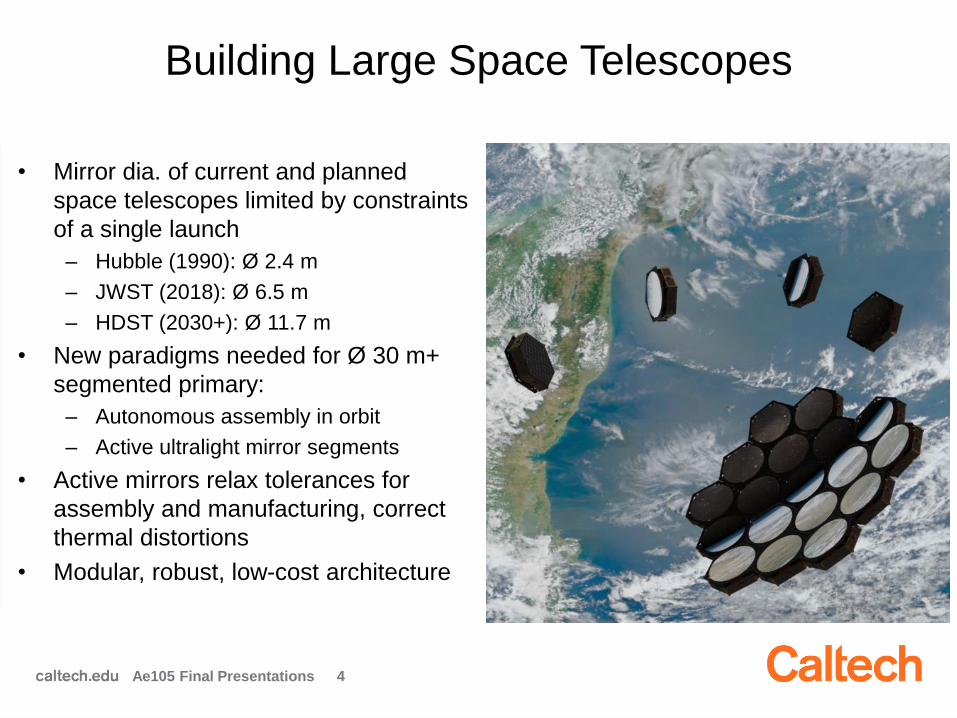
Building Large Space Telescopes
• Mirror dia. of current and planned
space telescopes limited by constraints
of a single launch
– Hubble (1990): Ø 2.4 m
– JWST (2018): Ø 6.5 m
– HDST (2030+): Ø 11.7 m
• New paradigms needed for Ø 30 m+
segmented primary:
– Autonomous assembly in orbit
– Active ultralight mirror segments
• Active mirrors relax tolerances for
assembly and manufacturing, correct
thermal distortions
• Modular, robust, low-cost architecture
JWST HDST
Ae105 Final Presentations 3
Building Large Space Telescopes
• Mirror dia. of current and planned
space telescopes limited by constraints
of a single launch
– Hubble (1990): Ø 2.4 m
– JWST (2018): Ø 6.5 m
– HDST (2030+): Ø 11.7 m
• New paradigms needed for Ø 30 m+
segmented primary:
– Autonomous assembly in orbit
– Active ultralight mirror segments
• Active mirrors relax tolerances for
assembly and manufacturing, correct
thermal distortions
• Modular, robust, low-cost architecture
Ae105 Final Presentations 4

AAReST Objectives
• Demonstrate key technologies:
– Autonomous assembly and reconfiguration of modular
spacecraft carrying mirror segments
– Active, lightweight deformable mirrors operating as segments in
a primary
• Operate for as long as necessary to accomplish the
objectives (~90 days)
• Gather engineering data to enable development of the
next system
Ae105 Final Presentations 5
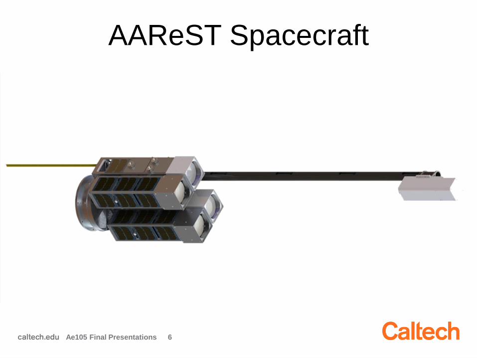
AAReST Spacecraft
Ae105 Final Presentations 6
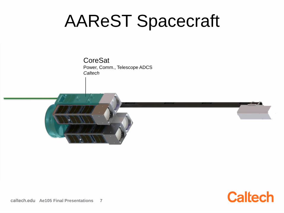
AAReST Spacecraft
Ae105 Final Presentations 7
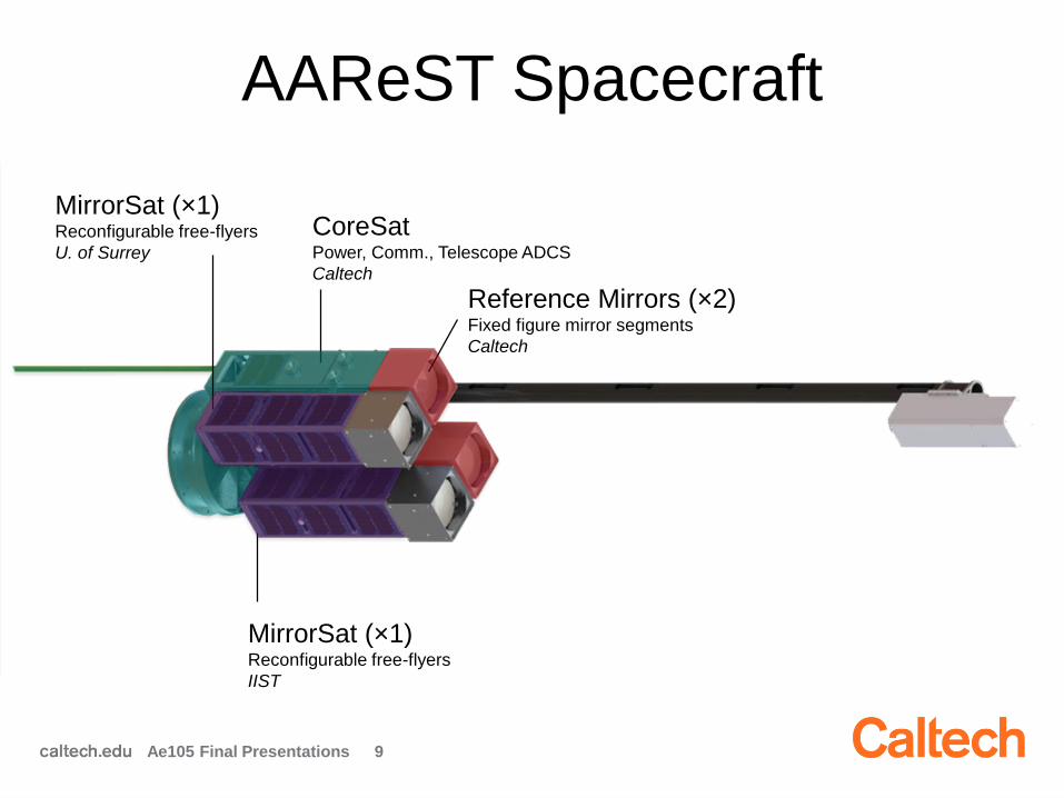
CoreSatPower, Comm., Telescope ADCS
Caltech
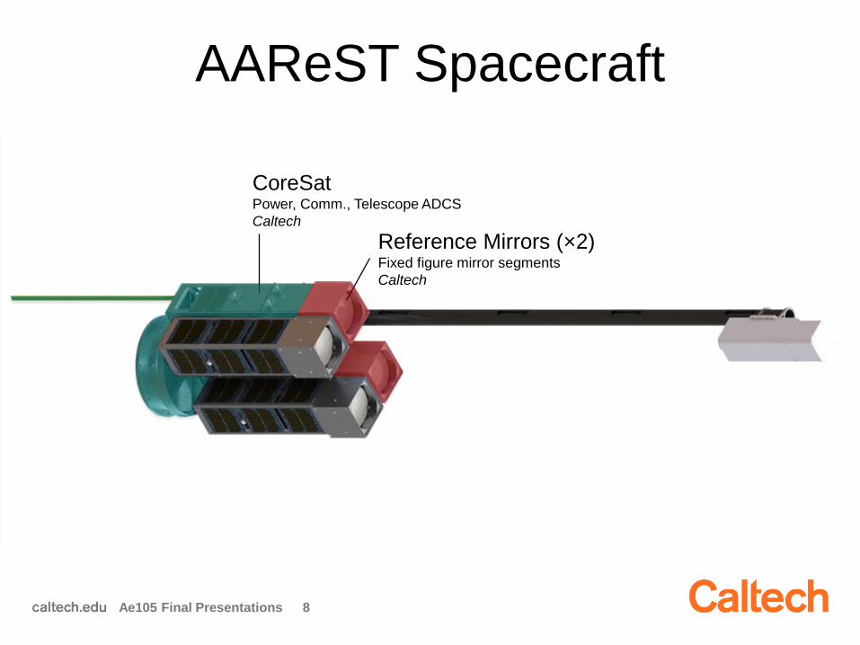
AAReST Spacecraft
Ae105 Final Presentations 8
CoreSatPower, Comm., Telescope ADCS
Caltech
Reference Mirrors (×2)Fixed figure mirror segments
Caltech
AAReST Spacecraft
Ae105 Final Presentations 9
CoreSatPower, Comm., Telescope ADCS
Caltech
Reference Mirrors (×2)Fixed figure mirror segments
Caltech
MirrorSat (×1)Reconfigurable free-flyers
U. of Surrey
MirrorSat (×1)Reconfigurable free-flyers
IIST
AAReST Spacecraft
Ae105 Final Presentations 10
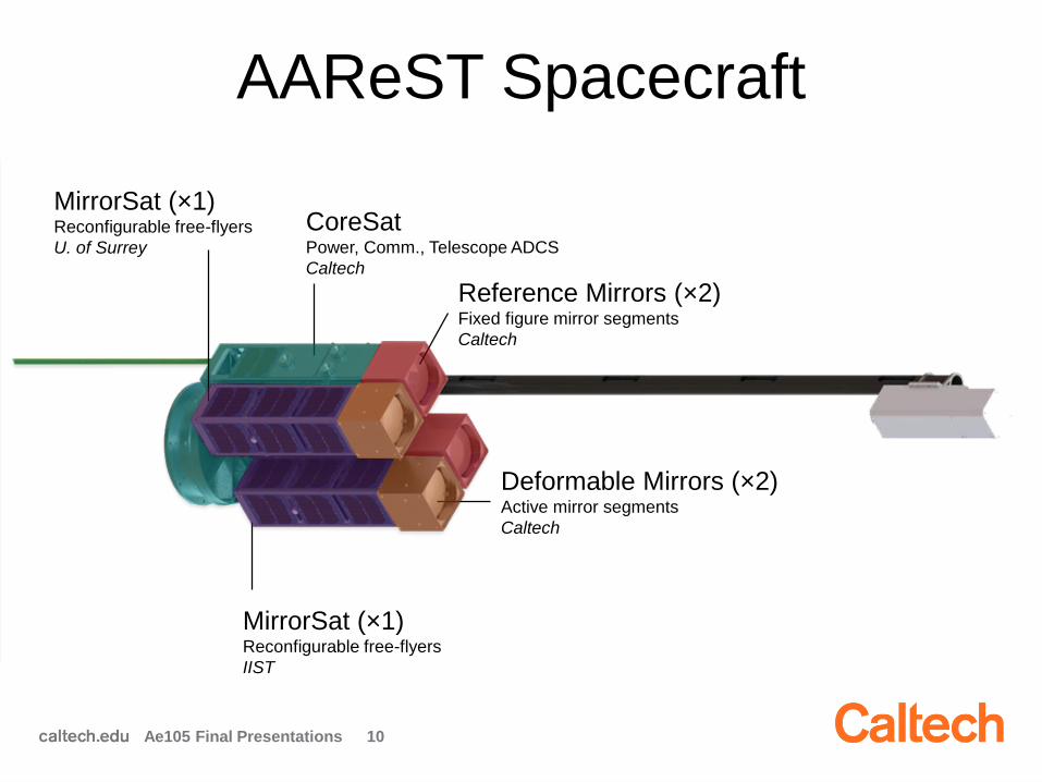
CoreSatPower, Comm., Telescope ADCS
Caltech
Reference Mirrors (×2)Fixed figure mirror segments
Caltech
MirrorSat (×1)Reconfigurable free-flyers
U. of Surrey
MirrorSat (×1)Reconfigurable free-flyers
IIST
Deformable Mirrors (×2)Active mirror segments
Caltech

AAReST Spacecraft
Ae105 Final Presentations 11
CoreSatPower, Comm., Telescope ADCS
Caltech
Reference Mirrors (×2)Fixed figure mirror segments
Caltech
MirrorSat (×1)Reconfigurable free-flyers
U. of Surrey
MirrorSat (×1)Reconfigurable free-flyers
IIST
Deformable Mirrors (×2)Active mirror segments
Caltech
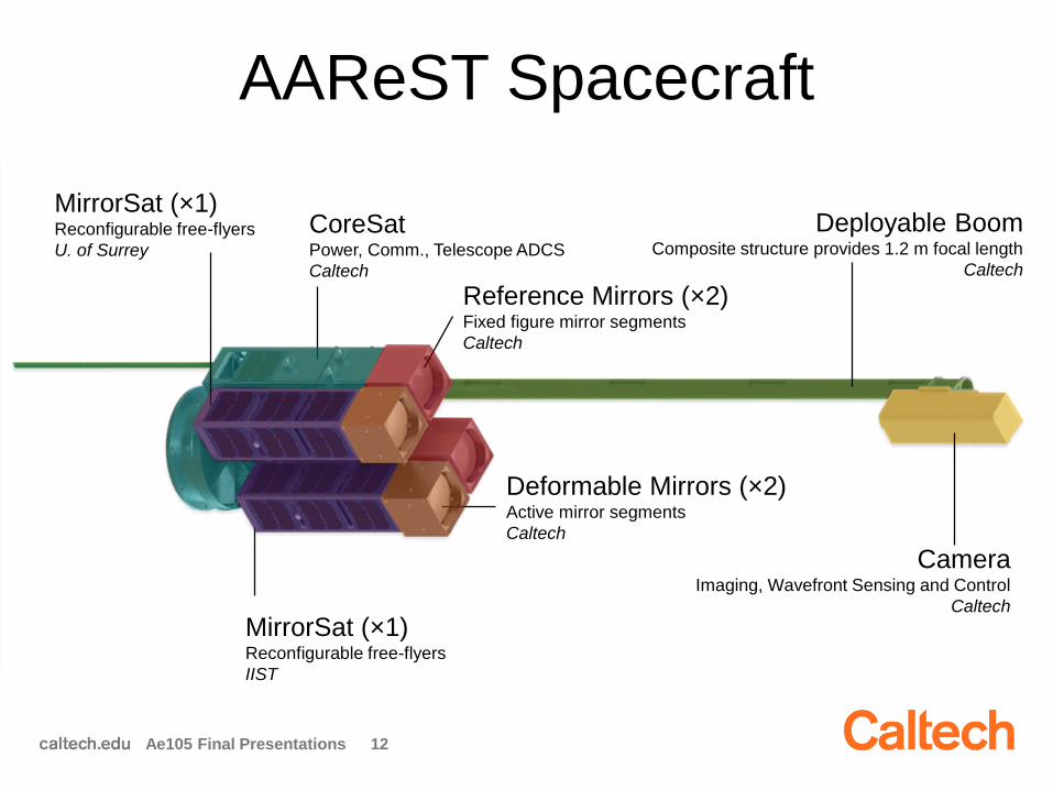
Deployable BoomComposite structure provides 1.2 m focal length
Caltech
AAReST Spacecraft
Ae105 Final Presentations 12
CoreSatPower, Comm., Telescope ADCS
Caltech
Reference Mirrors (×2)Fixed figure mirror segments
Caltech
MirrorSat (×1)Reconfigurable free-flyers
U. of Surrey
MirrorSat (×1)Reconfigurable free-flyers
IIST
Deformable Mirrors (×2)Active mirror segments
Caltech
Deployable BoomComposite structure provides 1.2 m focal length
Caltech
CameraImaging, Wavefront Sensing and Control
Caltech
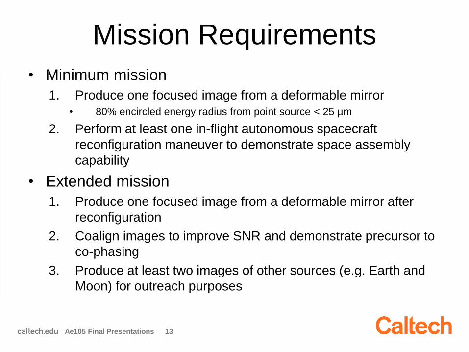
Mission Requirements
• Minimum mission
1. Produce one focused image from a deformable mirror
• 80% encircled energy radius from point source < 25 µm
2. Perform at least one in-flight autonomous spacecraft
reconfiguration maneuver to demonstrate space assembly
capability
• Extended mission
1. Produce one focused image from a deformable mirror after
reconfiguration
2. Coalign images to improve SNR and demonstrate precursor to
co-phasing
3. Produce at least two images of other sources (e.g. Earth and
Moon) for outreach purposes
Ae105 Final Presentations 13
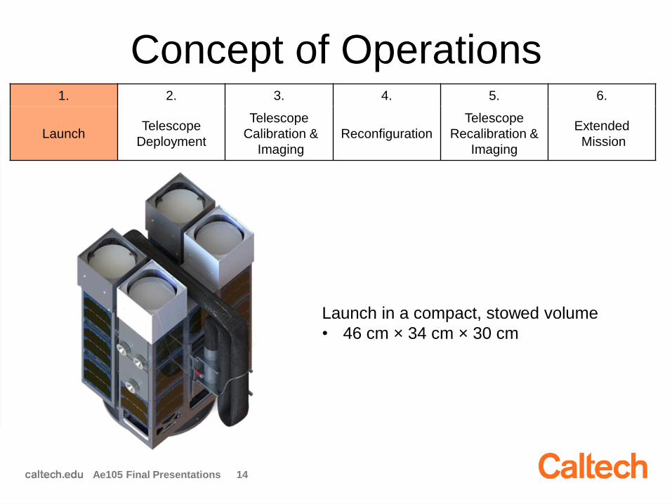
Concept of Operations1. 2. 3. 4. 5. 6.
LaunchTelescope
Deployment
Telescope
Calibration &
Imaging
Reconfiguration
Telescope
Recalibration &
Imaging
Extended
Mission
Launch in a compact, stowed volume
• 46 cm × 34 cm × 30 cm
Ae105 Final Presentations 14
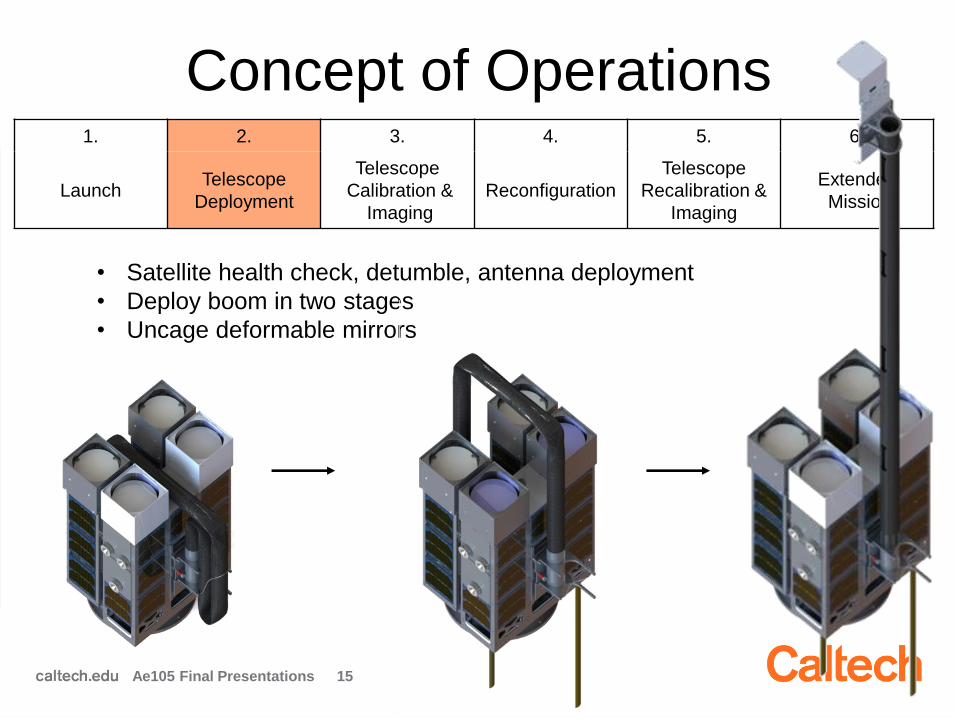
Concept of Operations
• Satellite health check, detumble, antenna deployment
• Deploy boom in two stages
• Uncage deformable mirrors
1. 2. 3. 4. 5. 6.
LaunchTelescope
Deployment
Telescope
Calibration &
Imaging
Reconfiguration
Telescope
Recalibration &
Imaging
Extended
Mission
Ae105 Final Presentations 15
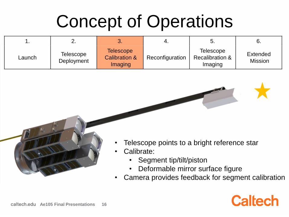
Concept of Operations
• Telescope points to a bright reference star
• Calibrate:
• Segment tip/tilt/piston
• Deformable mirror surface figure
• Camera provides feedback for segment calibration
1. 2. 3. 4. 5. 6.
LaunchTelescope
Deployment
Telescope
Calibration &
Imaging
Reconfiguration
Telescope
Recalibration &
Imaging
Extended
Mission
Ae105 Final Presentations 16

Concept of Operations
• MirrorSats release from CoreSat using electromagnets
• Fly out ~30 – 50 cm
• Re-dock into “wide” configuration
1. 2. 3. 4. 5. 6.
LaunchTelescope
Deployment
Telescope
Calibration &
Imaging
Reconfiguration
Telescope
Recalibration &
Imaging
Extended
Mission
Ae105 Final Presentations 17
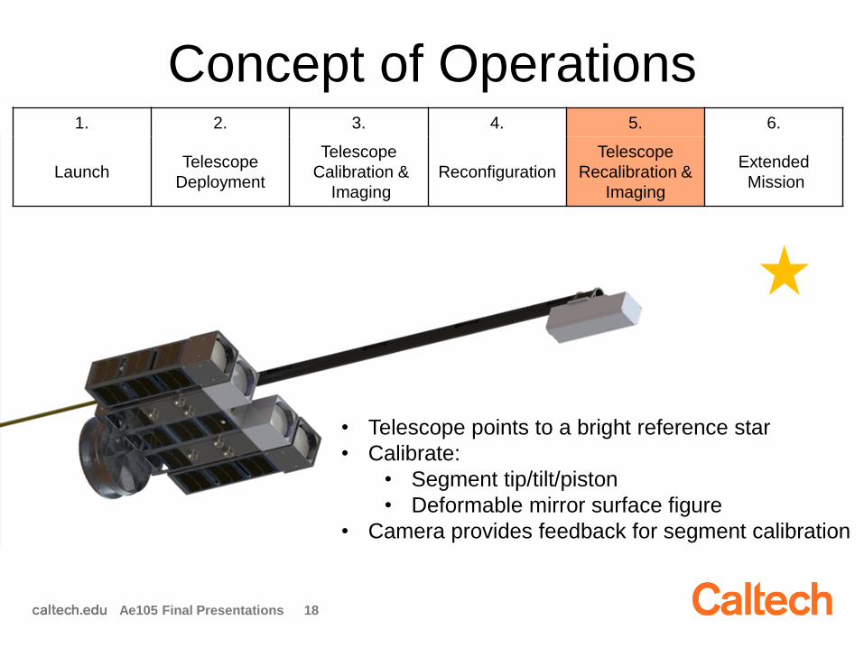
Concept of Operations
• Telescope points to a bright reference star
• Calibrate:
• Segment tip/tilt/piston
• Deformable mirror surface figure
• Camera provides feedback for segment calibration
1. 2. 3. 4. 5. 6.
LaunchTelescope
Deployment
Telescope
Calibration &
Imaging
Reconfiguration
Telescope
Recalibration &
Imaging
Extended
Mission
Ae105 Final Presentations 18
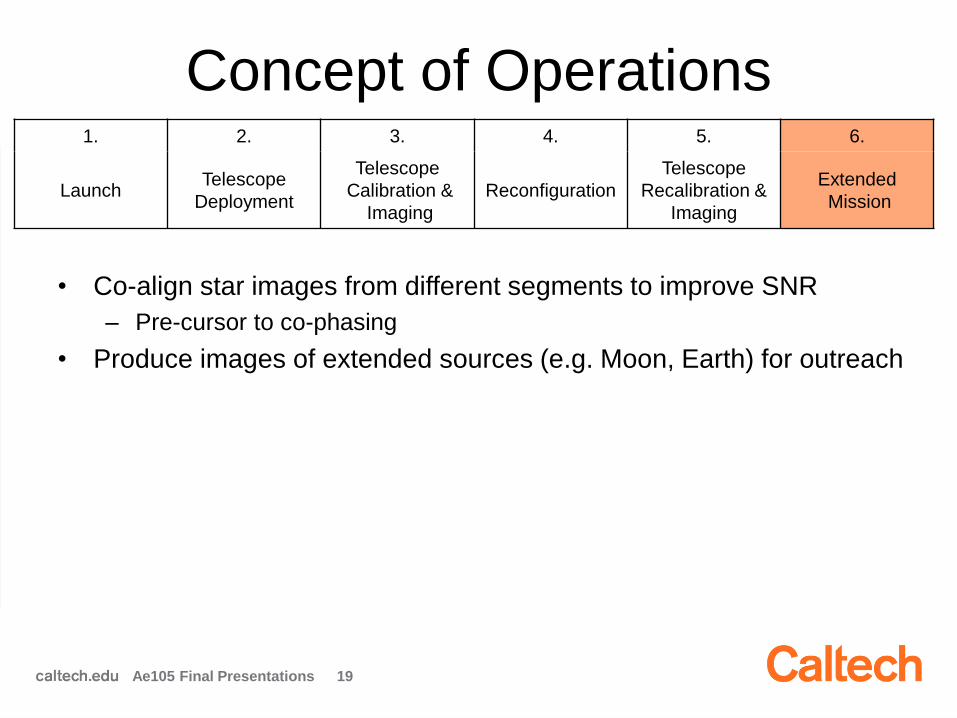
• Co-align star images from different segments to improve SNR
– Pre-cursor to co-phasing
• Produce images of extended sources (e.g. Moon, Earth) for outreach
Concept of Operations1. 2. 3. 4. 5. 6.
LaunchTelescope
Deployment
Telescope
Calibration &
Imaging
Reconfiguration
Telescope
Recalibration &
Imaging
Extended
Mission
Ae105 Final Presentations 19

AAReST History2008 November: Large Space Apertures KISS
workshop
2010 June: Ae105
– Initial mission design; mission requirement
definition
2012 September: Mission Concept Review
2013 September: Preliminary Design Review
2014 September: Detailed Design Review
2015 September: Complete Design Review
2016 June: Ae105
– Environmental testing of telescope systems
– Electronics and software design
2017 January: Telescope Complete Design
Review
2017 June: Ae105
– Preliminary design of CoreSat
– Hardware selection, spacecraft modelling &
analysis
2017 September: Complete Design Review of
three satellites
2010
2011
2012
2013
2014
2015
Ae105 Final Presentations 20

CoreSat Overview
Ae105 Final Presentation 21
Docking
ports
Launch vehicle
interface (LVI)
Custom 9U
structure
Rigid mirror
boxes
Antennas
Solar panels
Ae105 Projects:
• Systems Engineering
• Power
• Avionics & Comms
• ADCS
• Structures
Acknowledgement
The AAReST project is supported by:
• The Keck Institute for Space Studies
• Division of Engineering and Applied Science
• Provost’s Innovation in Education Fund
Ae105 Final Presentation 22

Outline
2:00 pm: Introduction & Welcome
2:15 pm: Systems Engineering
2:45 pm: Power
3:15 pm: Avionics & Comms
3:45 pm: ADCS
4:15 pm: Structures
Ae105 Final Presentations 23
Systems Engineering Team
Team:
Adrian Costantino
Kate Davies
Mohit Malik
Talia Minear
Bryan Sinkovec
Mentor: Fabien Royer

Systems Engineering Team Goals
25
• Orbit determination modeling
– Lifetime estimate
– Communications analysis
– Power collection validation
• Docking maneuver
– Kinematic analysis and orbital visualization
• Calibration targets and science targets
• CoreSat requirements, mass budget
Ae105 Final Presentation

Orbit Determination Modeling
26
• Polar Satellite Launch Vehicle (PSLV)
– Noon / midnight Sun-synchronous polar orbit
– Inclination ~ 98°
– Altitude 500 - 800 km
• Analysis tool: AGI STK
Credit: Indian Space Research
Organisation (ISRO)
PSLV
Ae105 Final Presentation
https://www.agi.com/downloads/media-center/logos/AGILogo2.jpg
27
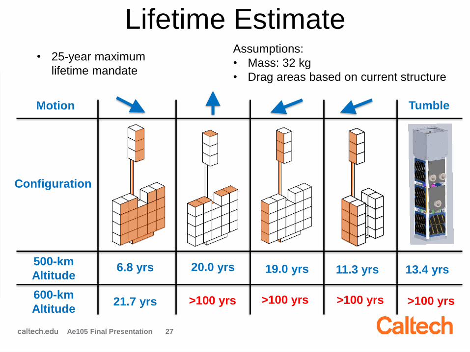
Motion
Configuration
Tumble
500-km
Altitude6.8 yrs
21.7 yrs
20.0 yrs
>100 yrs
19.0 yrs 11.3 yrs 13.4 yrs
Lifetime Estimate
600-km
Altitude
Ae105 Final Presentation
Assumptions:
• Mass: 32 kg
• Drag areas based on current structure
• 25-year maximum
lifetime mandate
>100 yrs >100 yrs >100 yrs

28
Motion
Configuration
Tumble
500-km
Altitude6.8 yrs
21.7 yrs
23.5 yrs
>100 yrs
18.7 yrs 11.4 yrs 13.4 yrs
Lifetime Estimate
600-km
Altitude
Ae105 Final Presentation
Assumptions:
• Mass: 32 kg
• Drag areas based on current structure
• 25-year maximum
lifetime mandate
>100 yrs >100 yrs >100 yrs
Takeaways
• Reduced design space to 500-600-km altitude
• Potential mitigation techniques for higher orbits:- Add thruster(s) to aid de-orbiting
- Add deployable solar panels to increase drag area
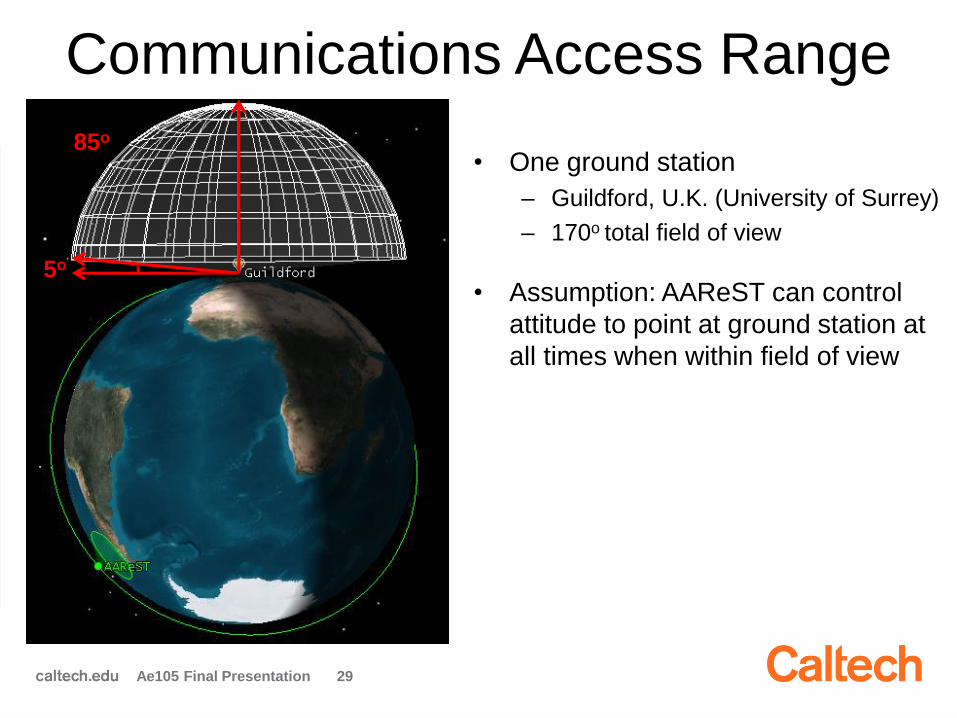
Communications Access Range
29
5o
85o
• One ground station
– Guildford, U.K. (University of Surrey)
– 170o total field of view
• Assumption: AAReST can control
attitude to point at ground station at
all times when within field of view
Ae105 Final Presentation

30
Access Time in 6-Month Time Interval
• Worst-case scenario (500-km altitude) is sufficient
• First iteration of link budgets generated based on assumptions and
design choices made by Communications Team
Ae105 Final Presentation
• Communications Team initially estimated 3 passes / day with
8 minutes of visibility / orbit ~ access of 24 min / day
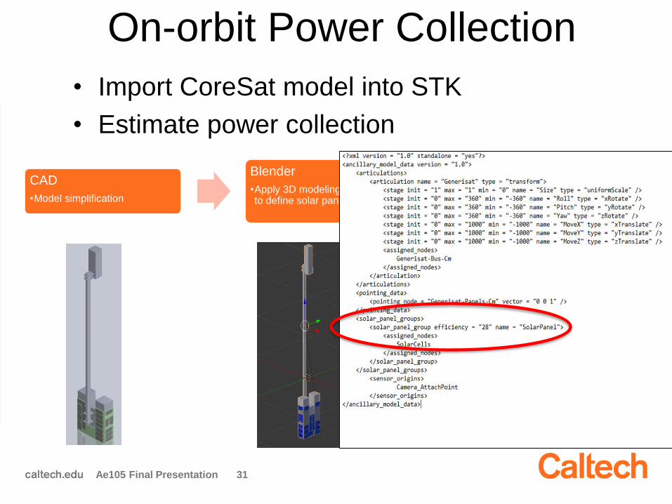
On-orbit Power Collection
CAD
•Model simplification
Blender
•Apply 3D modeling techniques to define solar panels
STK
•Power analysis
•Depends on geometry and orientation
• Import CoreSat model into STK
• Estimate power collection
Ae105 Final Presentation 31
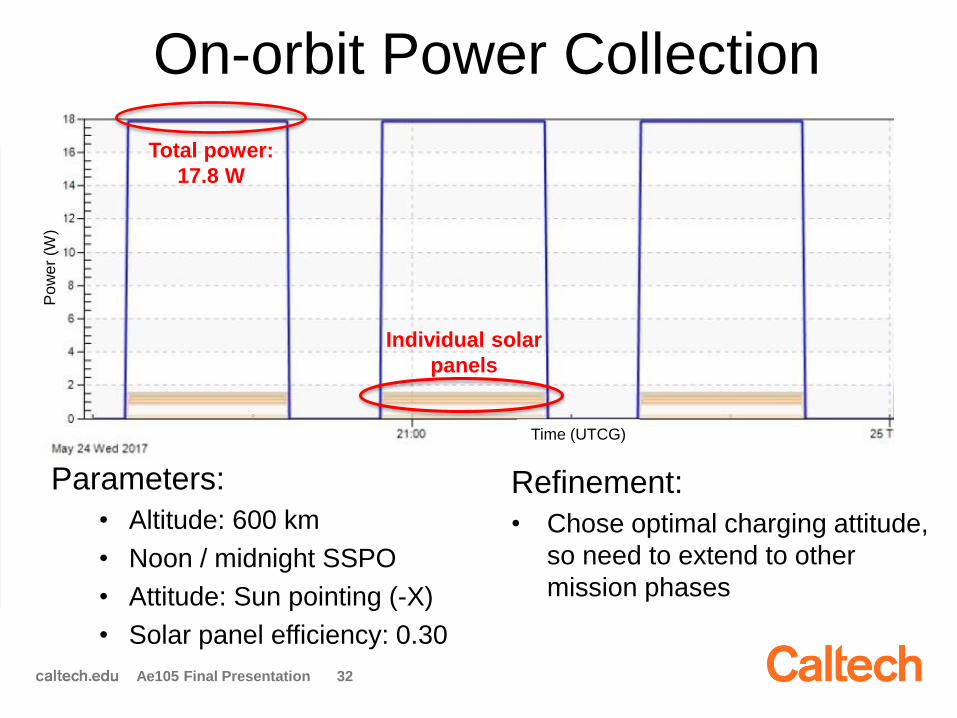
32
On-orbit Power Collection
Parameters:
• Altitude: 600 km
• Noon / midnight SSPO
• Attitude: Sun pointing (-X)
• Solar panel efficiency: 0.30
Refinement:
• Chose optimal charging attitude,
so need to extend to other
mission phases
Ae105 Final Presentation
Individual solar
panels
Po
we
r (W
)
Time (UTCG)
Total power:
17.8 W

33
On-Orbit Visualization
Ae105 Final Presentation
• Power collection • Docking maneuver
• Goals
– Implication on power consumption
during rendezvous
– Validation of kinematics analysis
Mission
control
sequence
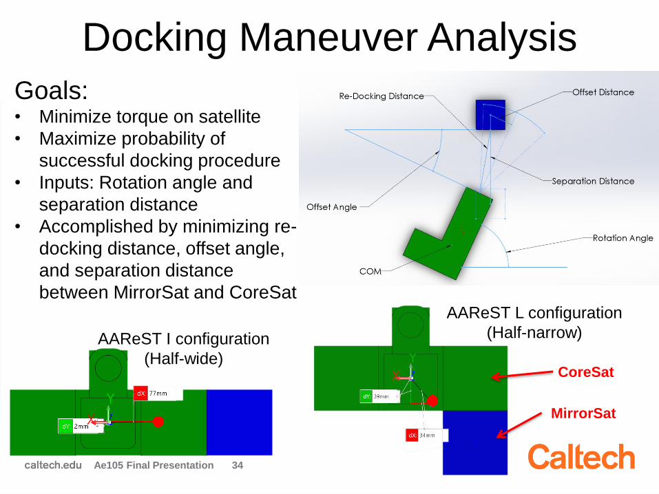
Docking Maneuver Analysis
34
AAReST I configuration
(Half-wide)
AAReST L configuration
(Half-narrow)
Goals:• Minimize torque on satellite
• Maximize probability of
successful docking procedure
• Inputs: Rotation angle and
separation distance
• Accomplished by minimizing re-
docking distance, offset angle,
and separation distance
between MirrorSat and CoreSat
Ae105 Final Presentation
MirrorSat
CoreSat

Docking Maneuver Visualization
35Ae105 Final Presentation
First maneuver
Second maneuver
MirrorSats
CoreSat

Starts in Full-Narrow Configuration
36
1.
Ae105 Final Presentation
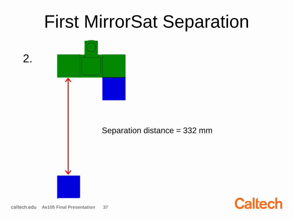
First MirrorSat Separation
37
2.
Separation distance = 332 mm
Ae105 Final Presentation
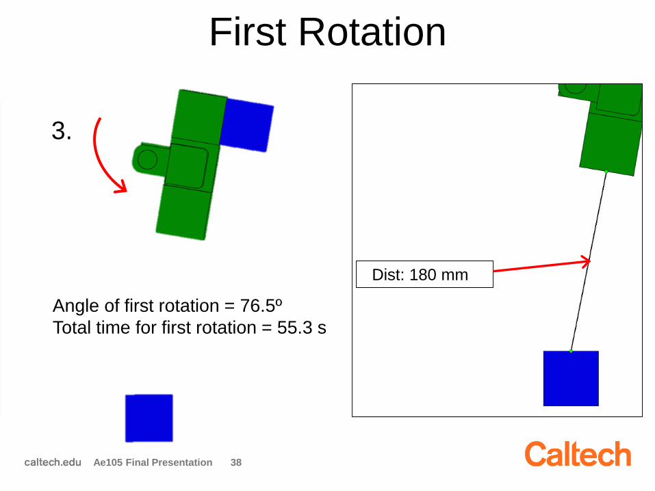
Angle of first rotation = 76.5º
Total time for first rotation = 55.3 s
First Rotation
38
3.
Ae105 Final Presentation
Dist: 180 mm
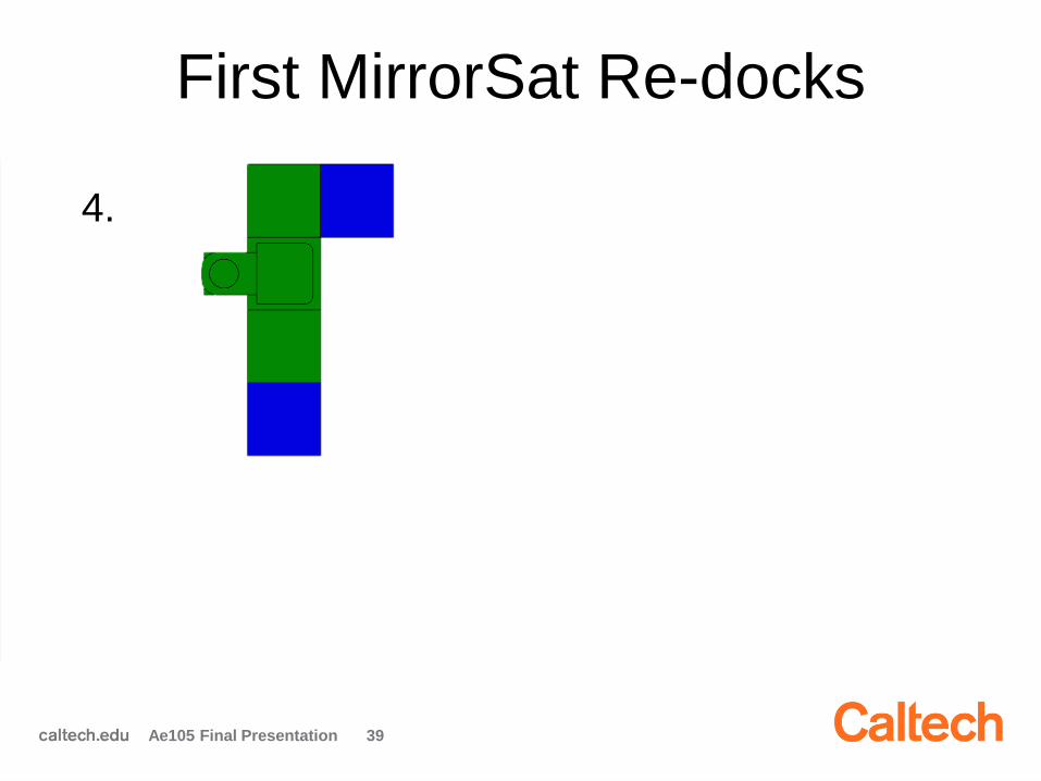
First MirrorSat Re-docks
39
4.
Ae105 Final Presentation
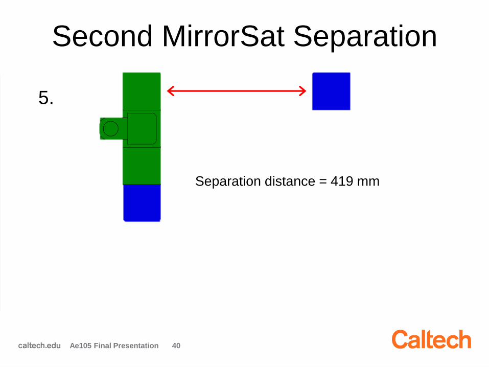
Second MirrorSat Separation
40
5.
Separation distance = 419 mm
Ae105 Final Presentation
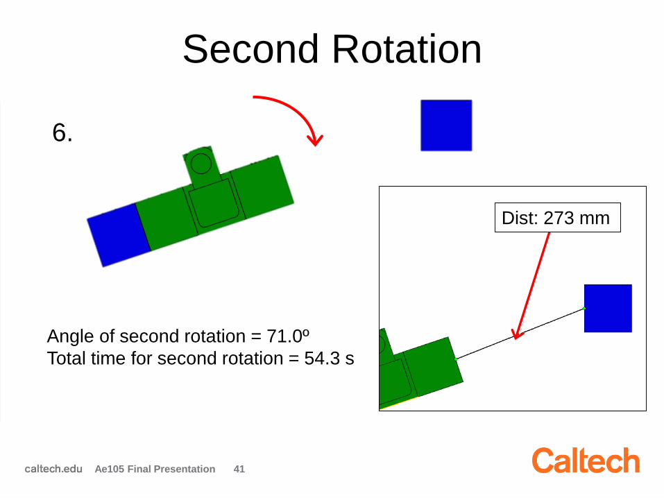
Second Rotation
41
6.
Angle of second rotation = 71.0º
Total time for second rotation = 54.3 s
Ae105 Final Presentation
Dist: 273 mm
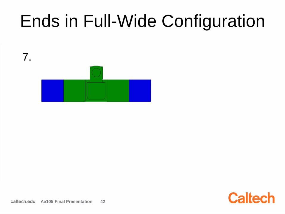
Ends in Full-Wide Configuration
42
7.
Ae105 Final Presentation
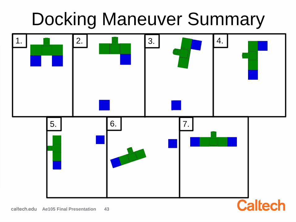
Docking Maneuver Summary
43
1. 2. 3. 4.
5. 6. 7.
Ae105 Final Presentation

Docking Numerical Optimization
• Score = C1*(offset distance) + C2*(misalignment angle) + C3*(re-docking distance)
• C1, C2 qualitatively assigned based on input from discussion with ADCS
• C1 > C2 >> C3
• C1:C2 sensitivity is low
• C3 was iterated upon so local minimum fell within the constrained region
• For this analysis: C1 = 3, C2 = 1, C3 = 0.035
44Ae105 Final Presentation

Docking Constraints
45
Acceptable offset tolerances:
5 cm = ±10º pitch / roll / yaw
15 cm = ±20º pitch / roll / yaw
30 cm = ±30º pitch / roll / yaw
Ae105 Final Presentation
Dark blue area: Near optimal
combination of rotation angle
and separation distance
Red dot: optimal solution
Acceptable capture area:
45º circular sector
R = 300 mm

Docking Constraints Visualized
46Ae105 Final Presentation
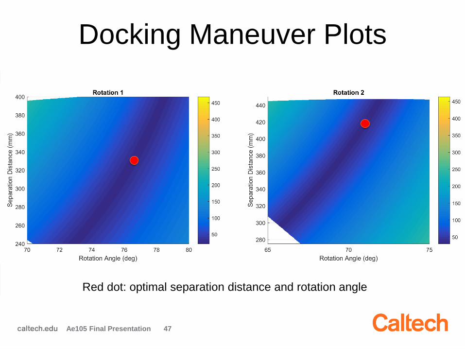
Docking Maneuver Plots
47Ae105 Final Presentation
Red dot: optimal separation distance and rotation angle

Optical Calibration Targets
• Repeated calibration of deformable mirrors
needed throughout mission
• Maneuver as little as possible to point at
calibration stars
• Limited range of star magnitude (-2 to 2) due
to science camera sensitivity
– 49 candidate stars (e.g. Sirius: -1.46)
• Use STK to determine visible stars
48Ae105 Final Presentation

Example Analysis for One Day
49Ae105 Final Presentation
• Many candidate
stars available,
must determine
when to point at
them
• May be limited
to eclipse
phases
One day

CoreSat Requirements Eye Chart
Ae105 Final Presentation 50
Avionics and Telecoms
AAReST must have a COTS transmitter/receiver operating at UHF/VHF
Pointing accuracy: error < 0.1° 3σ all axes
Vertical clearance of Launch Vehicle Interface, with respect to the MirrorSats, must be 5 cm
The batteries must be able to power the satellite during tumbling phases
Telescope must point away from the sun, at a minimum of 20° angular separation of the sun
ADCSStructuresPowerSystems
Ae105 Final Presentation 51
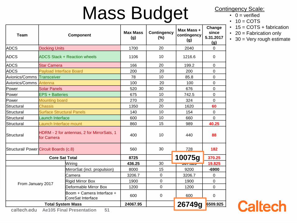
Contingency Scale:• 0 = verified
• 10 = COTS
• 15 = COTS + fabrication
• 20 = Fabrication only
• 30 = Very rough estimate
Mass Budget Team Component
Max Mass
(g)
Contingency
(%)
Max Mass +
contingency
(g)
Change
since
5.31.2017
(g)
ADCS Docking Units 1700 20 2040 0
ADCS ADCS Stack + Reaction wheels 1106 10 1216.6 0
ADCS Star Camera 166 20 199.2 0
ADCS Payload Interface Board 200 20 200 0
Avionics/Comms Transceiver 78 10 85.8 0
Avionics/Comms Antenna 100 20 100 0
Power Solar Panels 520 30 676 0
Power EPS + Batteries 675 10 742.5 0
Power Mounting board 270 20 324 0
Structural Chassis 1350 20 1620 60
Structural Surface Structural Panels 140 10 154 0
Structural Launch Interface 600 10 660 0
Structural Launch Interface mount 860 15 989 40.25
StructuralHDRM - 2 for antennas, 2 for MirrorSats, 1
for Camera400 10 440 88
Structural/ Power Circuit Boards (c.8) 560 30 728 182
Core Sat Total 8725 10075.1 370.25
Wiring 436.25 30 567.125 19.825
From January 2017
MirrorSat (incl. propulsion) 8000 15 9200 -6900
Camera 3206.7 0 3206.7 0
Rigid Mirror Box 1900 0 1900 0
Deformable Mirror Box 1200 0 1200 0
Boom + Camera Interface +
CoreSat Interface600 0 600 0
Total System Mass 24067.95 26748.925 -6509.925
10075g
26749g
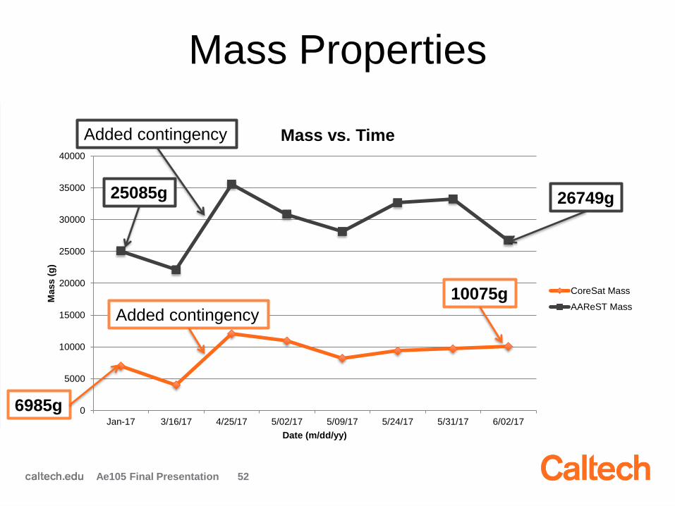
0
5000
10000
15000
20000
25000
30000
35000
40000
Jan-17 3/16/17 4/25/17 5/02/17 5/09/17 5/24/17 5/31/17 6/02/17
Mass (
g)
Date (m/dd/yy)
Mass vs. Time
CoreSat Mass
AAReST Mass
Mass Properties
Ae105 Final Presentation 52
10075g
26749g
Added contingency
Added contingency
6985g
25085g
Systems Team Summary
• Lifetime framework established
• Communications access determined
• Validation of power collection framework set up
• Optimal docking maneuver parametric framework
developed
• Calibration star access modeled
• CoreSat requirements document draft completed
• Mass budget template generated
53Ae105 Final Presentation
Future Work
• Adapt lifetime estimate for future structural
modifications
• Continue developing link budget
• Extend power analysis to complete mission
scenario
• Extend docking to include disturbances and
complete STK modeling
• Select calibration and science targets
• Continue tracking mass budget
54Ae105 Final Presentation
Questions?
55Ae105 Final Presentation

Outline
2:00 pm: Introduction & Welcome
2:15 pm: Systems Engineering
2:45 pm: Power
3:15 pm: Avionics & Comms
3:45 pm: ADCS
4:15 pm: Structures
Ae105 Final Presentations 65
AAReST CoreSat Power
System
Team:
Chris Bradley
Charlie Dorn
Juliane Preimesberger
Mentor: Ashish Goel
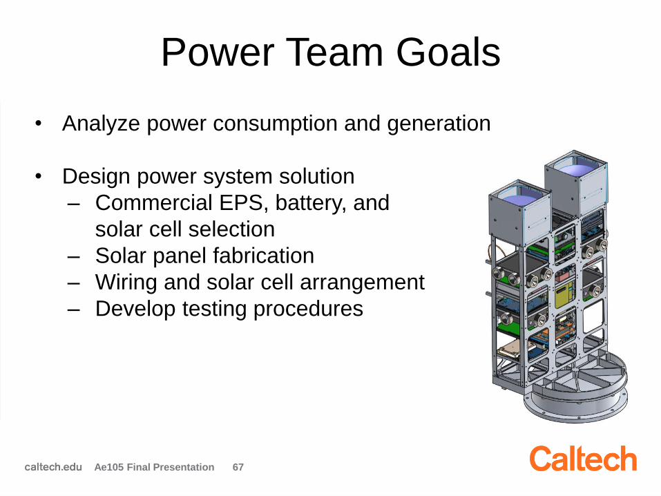
Power Team Goals
• Analyze power consumption and generation
• Design power system solution
– Commercial EPS, battery, and
solar cell selection
– Solar panel fabrication
– Wiring and solar cell arrangement
– Develop testing procedures
67Ae105 Final Presentation

High Level Requirements
• Power each subsystem, including MirrorSats, for all
operating modes
• Meet average and peak voltage and current
requirements for each subsystem
• Allocate enough energy storage for detumble and eclipse
68Ae105 Final Presentation

Operating mode Burn wire release (boom+antenna)Detumble
Actuator
release Nominal
Ground
comm Science Docking
Mirrorsat
Charging
Battery
heating
Configuration Narrow Narrow Narrow Both Both Both Both Both Both
Power Battery heater 6
EPS 0.5 0.5 0.5 0.5 0.5 0.5 0.5 0.5 0.5
ADCS CubeComputer 0.5 0.5 0.5 0.5 0.5 0.5 0.5 0.5 0.5
CubeSense 0.4 0.4 0.4 0.4 0.4 0.4 0.4 0.4 0.4
CubeControl 2.6 2.6 2.6 2.6 2.6 2.6 2.6 2.6 2.6
CubeWheel - Large 1.5 6.6 1.5 1.5 1.5 1.5 3.2 1.5 2.5
Star Camera 0.9 0.9
Avionics UHF/VHF Transceiver 5.4
Payload Interface Computer 3
Docking WiFi 1 1
Electromagnets 13
LEDs 1
Payload Rigid Mirror Payload 7
MirrorSat Charging 10
Camera 5
Others Boom Deployment 4
Actuators 25
Misc (health monitoring sensors) 0.5 0.5 0.5 0.5 0.5 0.5 0.5 0.5 0.5
Total Power (W) 9.73 11.04 30.94 5.94 11.34 22.81 23.51 15.94 12.94
Total Power with 30% Margin (W) 12.65 14.35 40.22 7.72 14.74 29.65 30.56 20.72 16.82
3.3 V bus peak current (A) 1.74 3.35 1.80 1.80 3.44 2.06 2.58 1.80 3.92
5 V bus peak current (A) 0 0 0 0 0 3.2 3 2 0
16 V bus peak current (A) 0.25 0 1.56 0 0 0 0 0 0
Max Mode Duration <2 min <2 orbits 30 sec free <8 min <10 min 2 min free 5 min
Power Budget
Ae105 Final Presentation 69 Good estimate
Subject to change

EPS Selection• Considered several CoTS options
• Three finalists
• Deciding factors– Power limit
– Number of input channels
– Compatibility with other systems
70
# Input
Channels
Max Current
In (A)
Max
Voltage In
(V)
# Output
Channels
Max Current
Out (A)
Max Voltage
Out (V)
Power
(W)
Comms Cost
Astro Dev 4 2 9 - 22 9 2 3.3,5 16 I2C -
NanoPower P60 6 2 32 9 2 3.3,5,8,12,18 64 CAN/I2C $19,000
NanoPower P31u 3 2 16 6 2.5 3.3,5 30 I2C $5,250
https://gomspace.com/Shop/subsystems/power-supplies/nanopower-p60.aspx
Gomspace NanoPower
P60
Ae105 Final Presentation
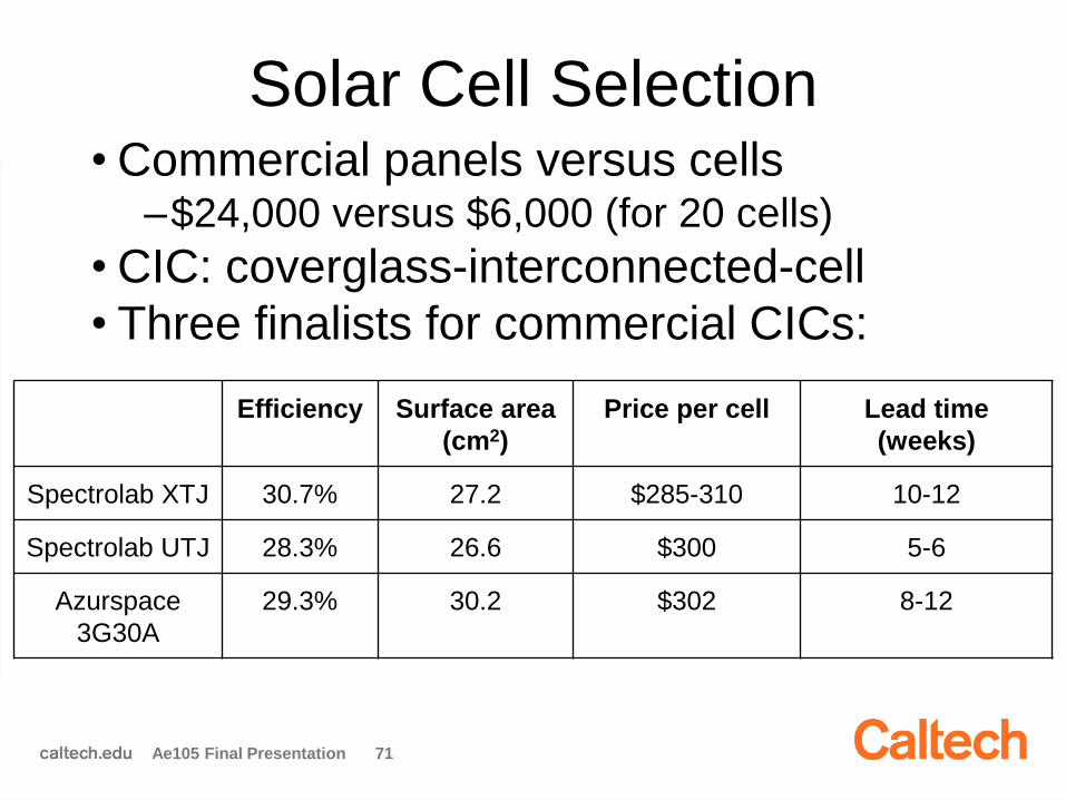
Solar Cell Selection• Commercial panels versus cells
–$24,000 versus $6,000 (for 20 cells)
• CIC: coverglass-interconnected-cell
• Three finalists for commercial CICs:
71
Efficiency Surface area
(cm2)
Price per cell Lead time
(weeks)
Spectrolab XTJ 30.7% 27.2 $285-310 10-12
Spectrolab UTJ 28.3% 26.6 $300 5-6
Azurspace
3G30A
29.3% 30.2 $302 8-12
Ae105 Final Presentation

Example Panel Fabrication• Modified CU Boulder procedure
• Finalized procedure steps:
– Cut tabs
– Laser cut double-sided Kapton tape
– Vacuum bagging
– Solder and add conductive epoxy
72
Align tape Vacuum bagging Add epoxy
Cut tabs
Tabs
PanelSilver
epoxy
Tape
Cell
Ae105 Final Presentation
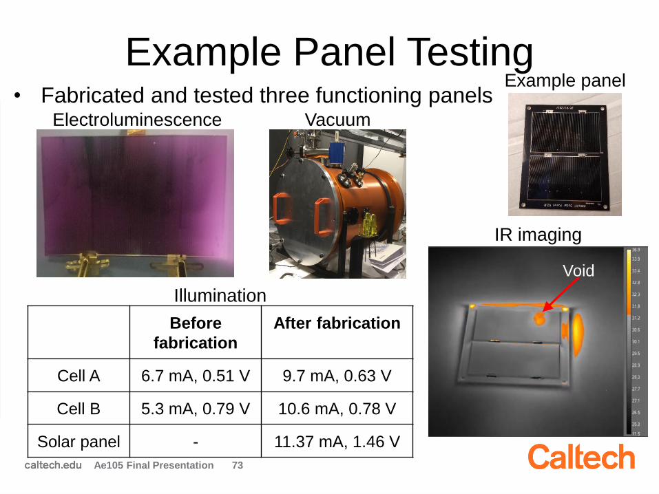
Example Panel Testing• Fabricated and tested three functioning panels
73
Before
fabrication
After fabrication
Cell A 6.7 mA, 0.51 V 9.7 mA, 0.63 V
Cell B 5.3 mA, 0.79 V 10.6 mA, 0.78 V
Solar panel - 11.37 mA, 1.46 V
Illumination
Electroluminescence Vacuum
IR imaging
Example panel
Void
Ae105 Final Presentation
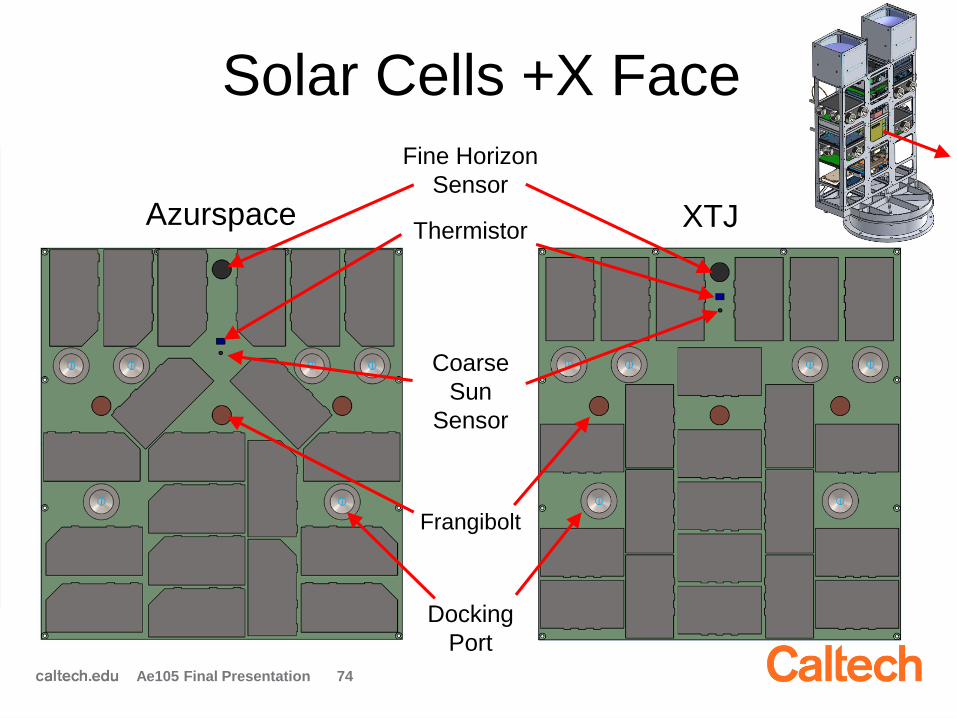
Solar Cells +X Face
74
Fine Horizon
Sensor
Coarse
Sun
Sensor
Docking
Port
Frangibolt
XTJThermistor
Ae105 Final Presentation
Azurspace

Solar Cells -X Face
75
Azurspace XTJ
Coarse
Sun
Sensor
Fine Sun
Sensor
Antenna
Mount
Thermistor
Ae105 Final Presentation
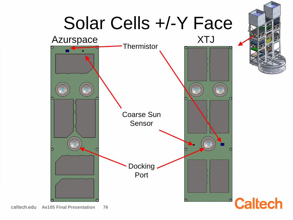
Solar Cells +/-Y Face
76
Azurspace XTJ
Coarse Sun
Sensor
Docking
Port
Thermistor
Ae105 Final Presentation
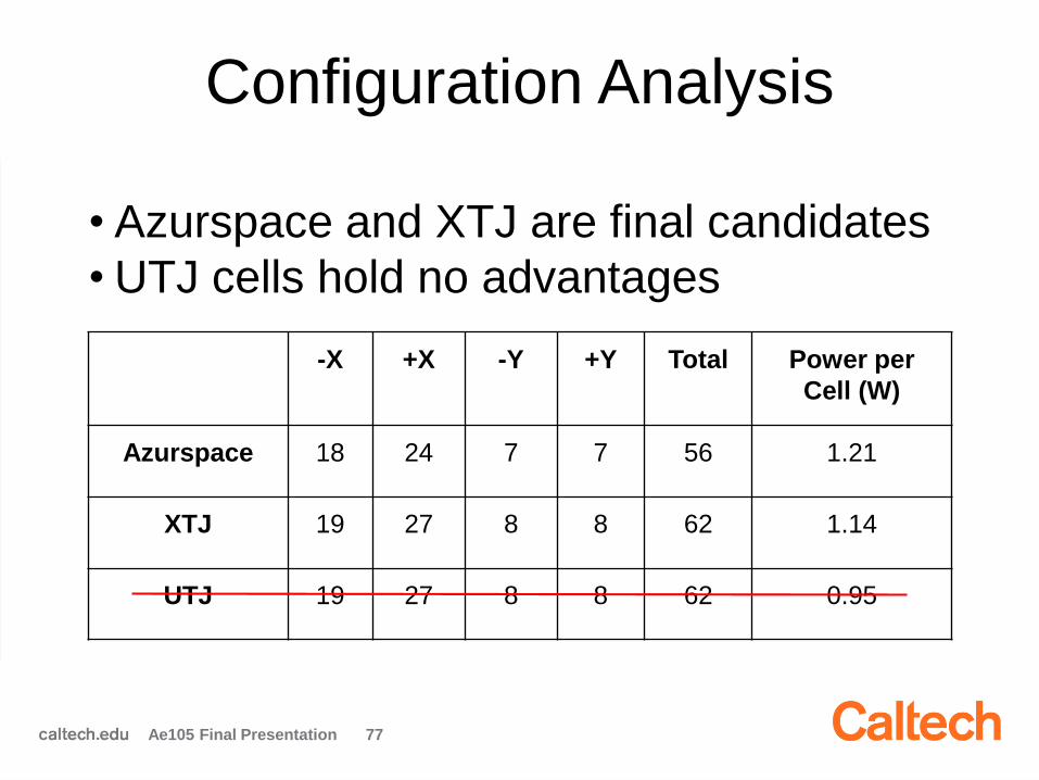
Configuration Analysis
• Azurspace and XTJ are final candidates
• UTJ cells hold no advantages
77
-X +X -Y +Y Total Power per
Cell (W)
Azurspace 18 24 7 7 56 1.21
XTJ 19 27 8 8 62 1.14
UTJ 19 27 8 8 62 0.95
Ae105 Final Presentation
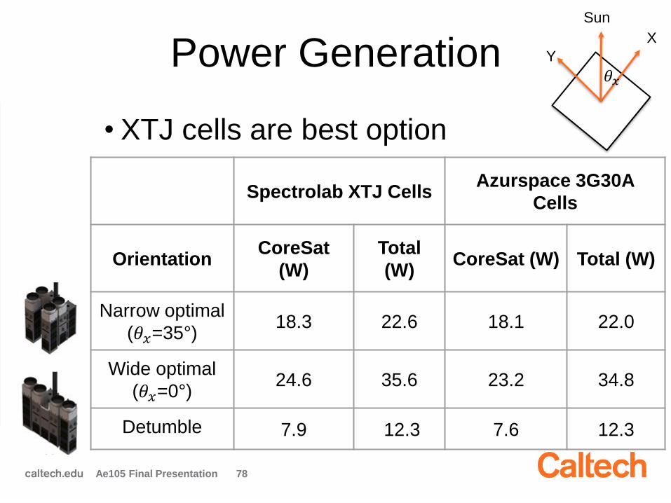
Power Generation
• XTJ cells are best option
78
Spectrolab XTJ CellsAzurspace 3G30A
Cells
OrientationCoreSat
(W)
Total
(W)CoreSat (W) Total (W)
Narrow optimal
(𝜃𝑥=35°)18.3 22.6 18.1 22.0
Wide optimal
(𝜃𝑥=0°)24.6 35.6 23.2 34.8
Detumble 7.9 12.3 7.6 12.3
Ae105 Final Presentation
Y
X
Sun
𝜃𝑥
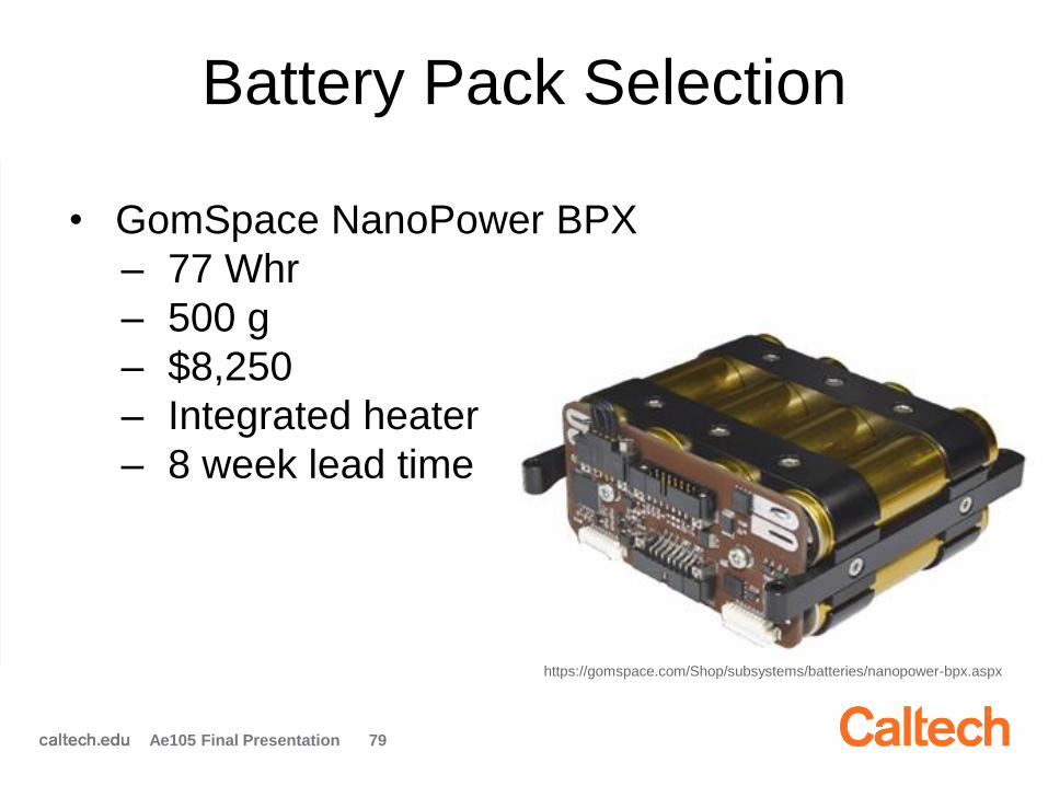
Battery Pack Selection
• GomSpace NanoPower BPX
– 77 Whr
– 500 g
– $8,250
– Integrated heater
– 8 week lead time
79
https://gomspace.com/Shop/subsystems/batteries/nanopower-bpx.aspx
Ae105 Final Presentation
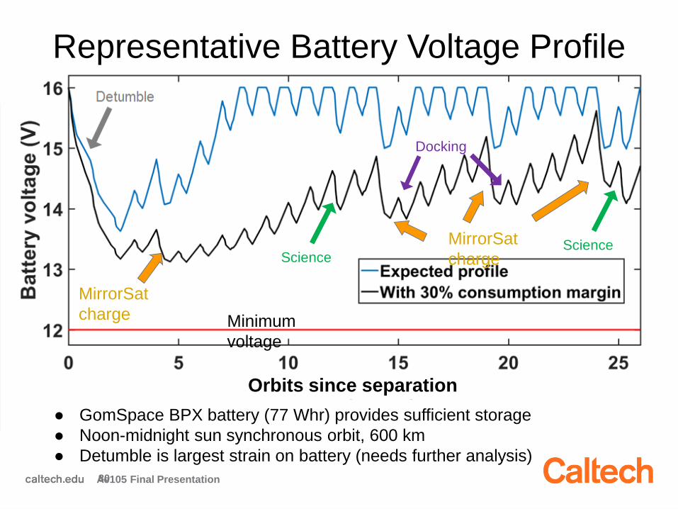
Representative Battery Voltage Profile
80
MirrorSat
charge
MirrorSat
charge
Science
Docking
Science
Minimum
voltage
Orbits since separation
● GomSpace BPX battery (77 Whr) provides sufficient storage
● Noon-midnight sun synchronous orbit, 600 km
● Detumble is largest strain on battery (needs further analysis)
Ae105 Final Presentation

Solar Cell Wiring and Shadowing
● Inefficient wiring of shadowed
cells leads to large power losses
● Shadowing due to folded
antennas, boom
● Folded antenna shading analysis
14.5
W11.3
W8.1 W
Ae105 Final Presentation 81
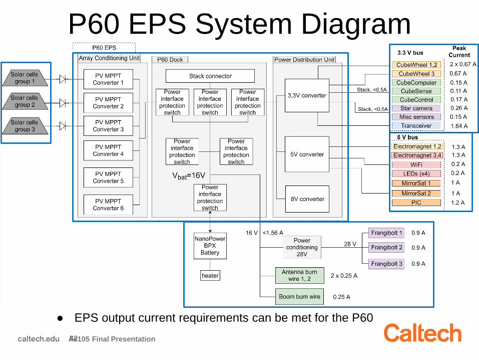
P60 EPS System Diagram
82
● EPS output current requirements can be met for the P60
Ae105 Final Presentation
Summary
• Analyzed power generation and consumption
• Selected components: P60 EPS, BPX battery, XTJ
solar cells
• Developed fabrication procedure
• Designed optimal solar cell layout
• Created EPS wiring diagram
83Ae105 Final Presentation
Future Work
• Order power system components
• Finalize solar cell mounting configuration
• Fabricate flight solar panels
• Finalize system wiring scheme
• Test components and systems
84Ae105 Final Presentation
Questions?
85Ae105 Final Presentation
Outline
2:00 pm: Introduction & Welcome
2:15 pm: Systems Engineering
2:45 pm: Power
3:15 pm: Avionics & Comms
3:45 pm: ADCS
4:15 pm: Structures
Ae105 Final Presentations 90
Avionics and Telecoms Team
Mentors
Thibaud Talon
Maria Sakovsky
Nishant Desai
Jorge Llop
Antonio Pedivellano
Eduardo Plascencia

Team Goals
• Design, build, and test communications system capable of establishing data
transmission between AAReST and ground station– Uplink
– Downlink
• Develop CoreSat telemetry structure
• Use FlatSat to begin testing avionics
Ae105 Final Presentation 92
Jorge’s workAntonio &
Eduardo’s
work
Nishant’s
work
Driving RequirementsAvionics
Ae105 Final Presentation 93
• Need protocols to ensure telemetry, data, and
commands are transmitted and received in a reliable,
error-free way
• Must use real-time and interrupt-driven software within
satellite
• Implement specified On-Board Computer (OBC)
interfaces:
– I2C
– UART
• Monitor safety variables of satellite and engage safe
mode if needed
Driving RequirementsCommunications
Ae105 Final Presentation 94
• Satellite needs to communicate with the ground station
using amateur band radio (VHF uplink / UHF downlink)
• Power consumption must stay within the capabilities of
the power system
• Antennas must be folded during launch and deployed
once in orbit
• Must find an optimal position for the antenna in order to
reduce losses due to pointing and EM interference with
the CoreSat

FlatSat
Ae105 Final Presentation 95
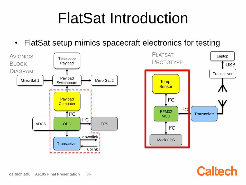
FlatSat Introduction
• FlatSat setup mimics spacecraft electronics for testing
Ae105 Final Presentation 96
FLATSAT
PROTOTYPE
Temp.
Sensor
I
2
C
TransceiverEFM32
MCU
I2C
Mock EPS
I2C
Transceiver
Laptop
USB
AVIONICS
BLOCK
DIAGRAM
ADCS OBC EPS
Transceiver
Payload
Computer
Payload
Switchboard
Telescope
Payload
MirrorSat 1 MirrorSat 2
downlink
uplink
I2C
I2C
I2C

FlatSat Introduction
• FlatSat setup mimics spacecraft electronics for testing
Ae105 Final Presentation 97
FLATSAT
IN LAB
EFM32
Mock
Antenna
Temperature
Sensor
Mock
EPS
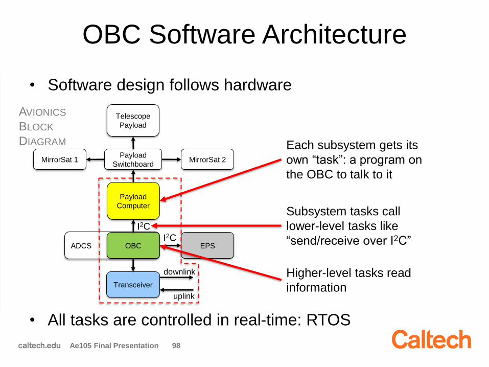
OBC Software Architecture
Ae105 Final Presentation 98
• Software design follows hardware
• All tasks are controlled in real-time: RTOS
AVIONICS
BLOCK
DIAGRAM
ADCS OBC EPS
Transceiver
Payload
Computer
Payload
Switchboard
Telescope
Payload
MirrorSat 1 MirrorSat 2
downlink
uplink
I2C
I2C
Each subsystem gets its
own “task”: a program on
the OBC to talk to it
Subsystem tasks call
lower-level tasks like
“send/receive over I2C”
Higher-level tasks read
information
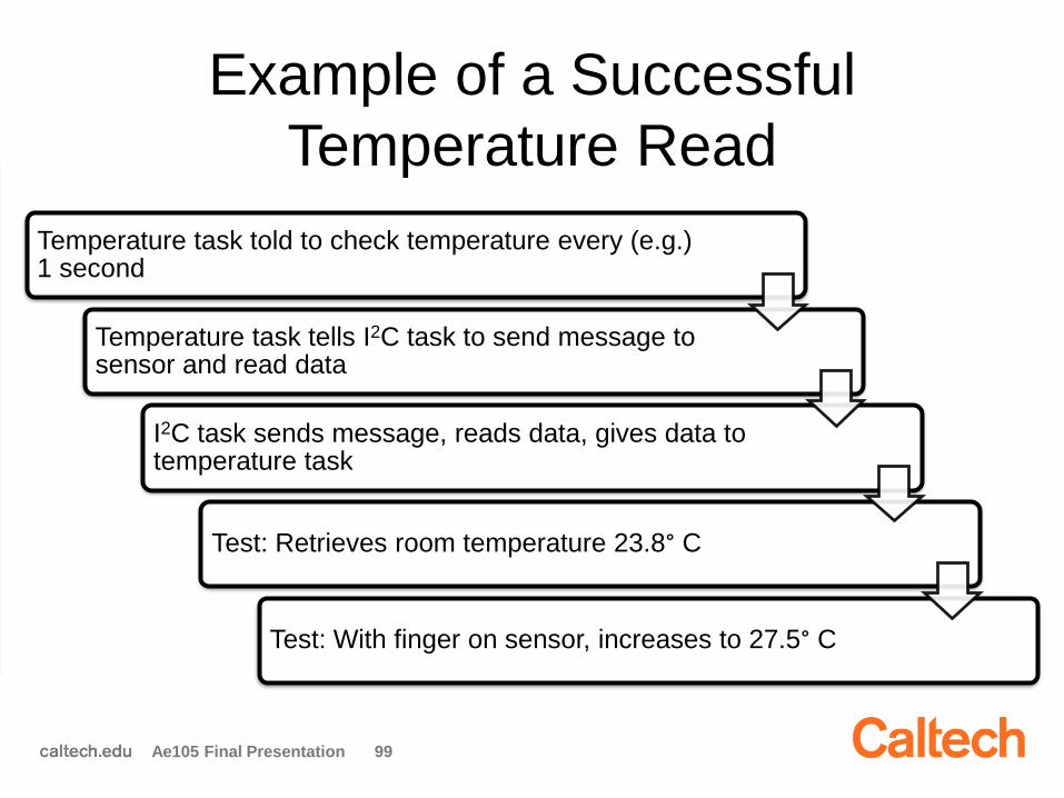
Example of a Successful
Temperature Read
Ae105 Final Presentation 99
Temperature task told to check temperature every (e.g.) 1 second
Temperature task tells I2C task to send message to sensor and read data
I2C task sends message, reads data, gives data to temperature task
Test: Retrieves room temperature 23.8° C
Test: With finger on sensor, increases to 27.5° C
Challenges and Results
Challenges:
• Compatibility: getting I2C functions to work with RTOS
• Timing between RTOS and EFM32
• Memory allocation of RTOS
Results:
• Wrote example software to retrieve temperature over I2C
– Can be replicated to any I2C-interfacing component
• Tested software and demonstrated that it works
Ae105 Final Presentation 100
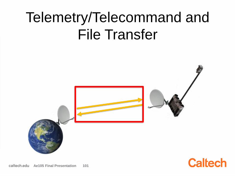
Telemetry/Telecommand and
File Transfer
Ae105 Final Presentation 101
Saratoga File Transfer Protocol
File Transfer Protocol:
• Saratoga protocol is the best fit for the mission: fast,
scalable, simple, and robust
• Saratoga protocol has heritage from Surrey missions
Ae105 Final Presentation 102
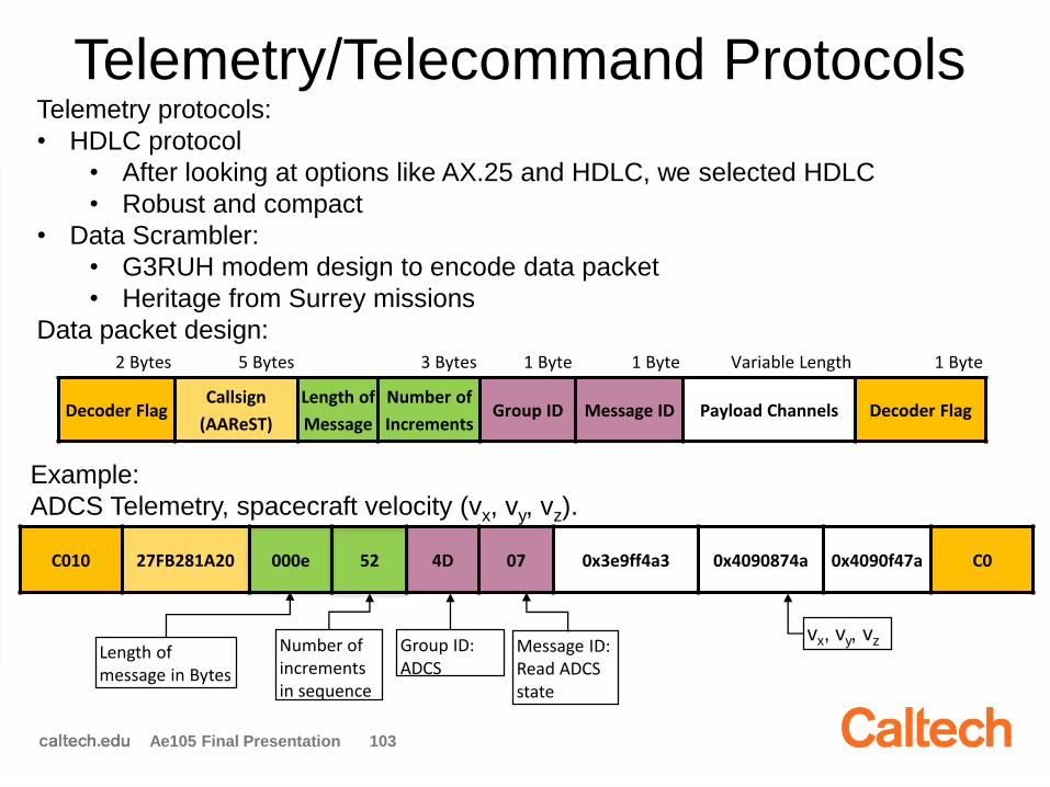
C010 27FB281A20 000e 52 4D 07 0x3e9ff4a3 0x4090874a 0x4090f47a C0
Number of increments in sequence
Group ID: ADCS
Message ID: Read ADCS state
vx, vy, vzLength of message in Bytes
2 Bytes 5 Bytes 3 Bytes 1 Byte 1 Byte Variable Length 1 Byte
Decoder FlagCallsign
(AAReST)
Length of
Message
Number of
IncrementsGroup ID Message ID Payload Channels Decoder Flag
Telemetry/Telecommand ProtocolsTelemetry protocols:
• HDLC protocol
• After looking at options like AX.25 and HDLC, we selected HDLC
• Robust and compact
• Data Scrambler:
• G3RUH modem design to encode data packet
• Heritage from Surrey missions
Data packet design:
Example:
ADCS Telemetry, spacecraft velocity (vx, vy, vz).
Ae105 Final Presentation 103
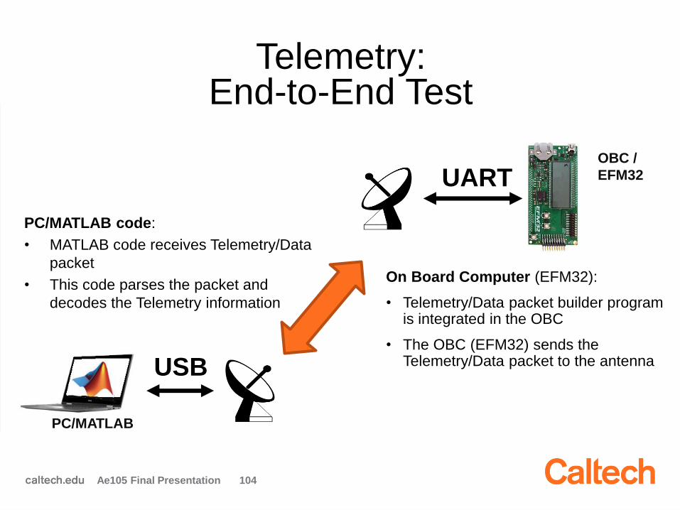
UART
USB
OBC /
EFM32
PC/MATLAB
Telemetry: End-to-End Test
On Board Computer (EFM32):
• Telemetry/Data packet builder program is integrated in the OBC
• The OBC (EFM32) sends the Telemetry/Data packet to the antenna
PC/MATLAB code:
• MATLAB code receives Telemetry/Data
packet
• This code parses the packet and
decodes the Telemetry information
Ae105 Final Presentation 104
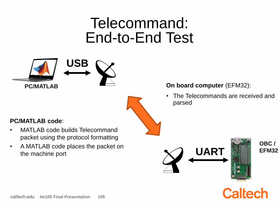
UART
USB
OBC /
EFM32
PC/MATLAB
Telecommand: End-to-End Test
On board computer (EFM32):
• The Telecommands are received and parsed
PC/MATLAB code:
• MATLAB code builds Telecommand
packet using the protocol formatting
• A MATLAB code places the packet on
the machine port
Ae105 Final Presentation 105
Communications
Ae105 Final Presentation 106
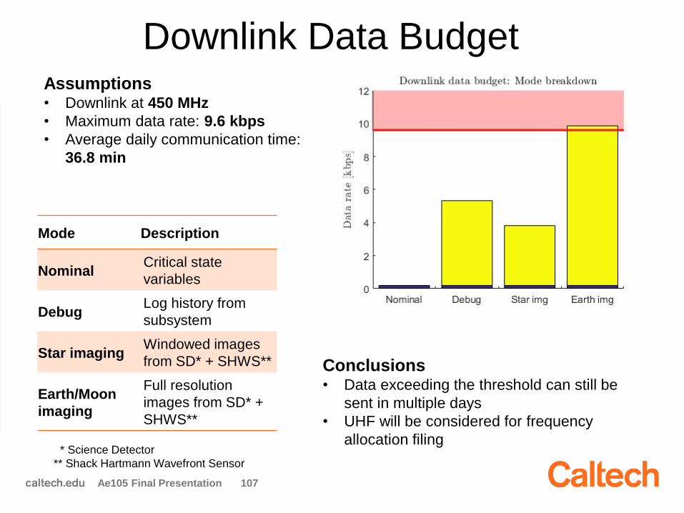
Downlink Data BudgetAssumptions• Downlink at 450 MHz
• Maximum data rate: 9.6 kbps
• Average daily communication time:
36.8 min
Conclusions• Data exceeding the threshold can still be
sent in multiple days
• UHF will be considered for frequency
allocation filing
Mode Description
NominalCritical state
variables
DebugLog history from
subsystem
Star imagingWindowed images
from SD* + SHWS**
Earth/Moon
imaging
Full resolution
images from SD* +
SHWS**
* Science Detector
** Shack Hartmann Wavefront Sensor
Ae105 Final Presentation 107
Transceiver Selection Criteria
• Transmit at UHF (400-450 MHz) and
receive at VHF (100-150 MHz)
• Conforms to CubeSat size format
• Data protocol (HDLC) and bus interface
(not I2C) requirements
Ae105 Final Presentation 108
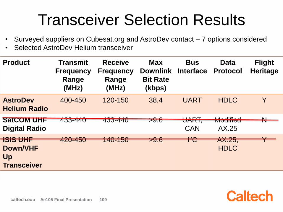
Transceiver Selection Results
Product Transmit
Frequency
Range
(MHz)
Receive
Frequency
Range
(MHz)
Max
Downlink
Bit Rate
(kbps)
Bus
Interface
Data
Protocol
Flight
Heritage
AstroDev
Helium Radio
400-450 120-150 38.4 UART HDLC Y
SatCOM UHF
Digital Radio
433-440 433-440 >9.6 UART,
CAN
Modified
AX.25
N
ISIS UHF
Down/VHF
Up
Transceiver
420-450 140-150 >9.6 I2C AX.25,
HDLC
Y
• Surveyed suppliers on Cubesat.org and AstroDev contact – 7 options considered
• Selected AstroDev Helium transceiver
Ae105 Final Presentation 109
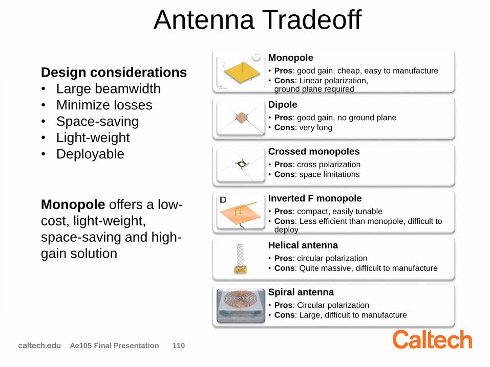
Antenna Tradeoff
Monopole
• Pros: good gain, cheap, easy to manufacture
• Cons: Linear polarization,ground plane required
Dipole
• Pros: good gain, no ground plane
• Cons: very long
Crossed monopoles
• Pros: cross polarization
• Cons: space limitations
Inverted F monopole
• Pros: compact, easily tunable
• Cons: Less efficient than monopole, difficult to deploy
Helical antenna
• Pros: circular polarization
• Cons: Quite massive, difficult to manufacture
Spiral antenna
• Pros: Circular polarization
• Cons: Large, difficult to manufacture
Design considerations
• Large beamwidth
• Minimize losses
• Space-saving
• Light-weight
• Deployable
Monopole offers a low-
cost, light-weight,
space-saving and high-
gain solution
Ae105 Final Presentation 110
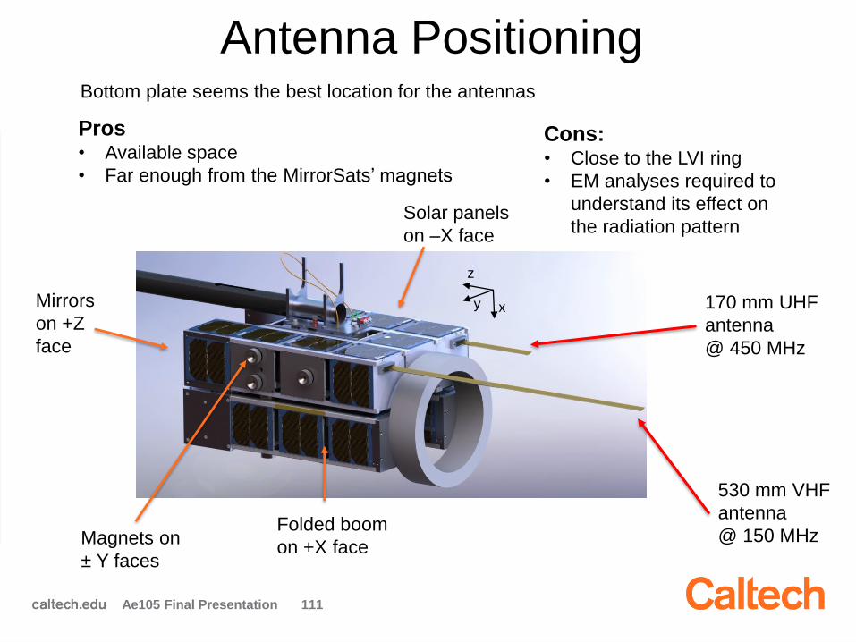
Antenna Positioning
530 mm VHF
antenna
@ 150 MHz
170 mm UHF
antenna
@ 450 MHz
xy
z
Solar panels
on –X face
Mirrors
on +Z
face
Magnets on
± Y faces
Folded boom
on +X face
Bottom plate seems the best location for the antennas
Pros• Available space
• Far enough from the MirrorSats’ magnets
Cons:• Close to the LVI ring
• EM analyses required to
understand its effect on
the radiation pattern
Ae105 Final Presentation 111
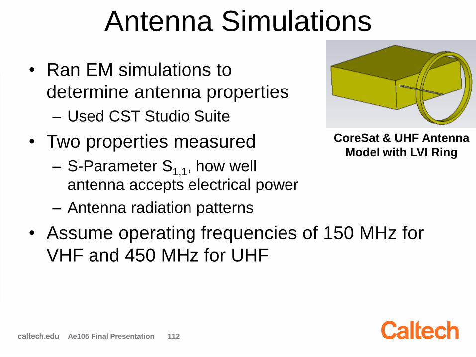
Antenna Simulations
• Ran EM simulations to
determine antenna properties
– Used CST Studio Suite
• Two properties measured
– S-Parameter S1,1, how well
antenna accepts electrical power
– Antenna radiation patterns
• Assume operating frequencies of 150 MHz for
VHF and 450 MHz for UHF
CoreSat & UHF Antenna
Model with LVI Ring
Ae105 Final Presentation 112

Antenna EM Simulations S-Parameter, UHF
• Requirement to operate with S-Parameter < -10 dB not satisfied here for any
antenna length at the operating frequency, 450 MHz.
− Options include angling antenna, placing it on –X face
Magnitude (
dB
)
Ae105 Final Presentation 113
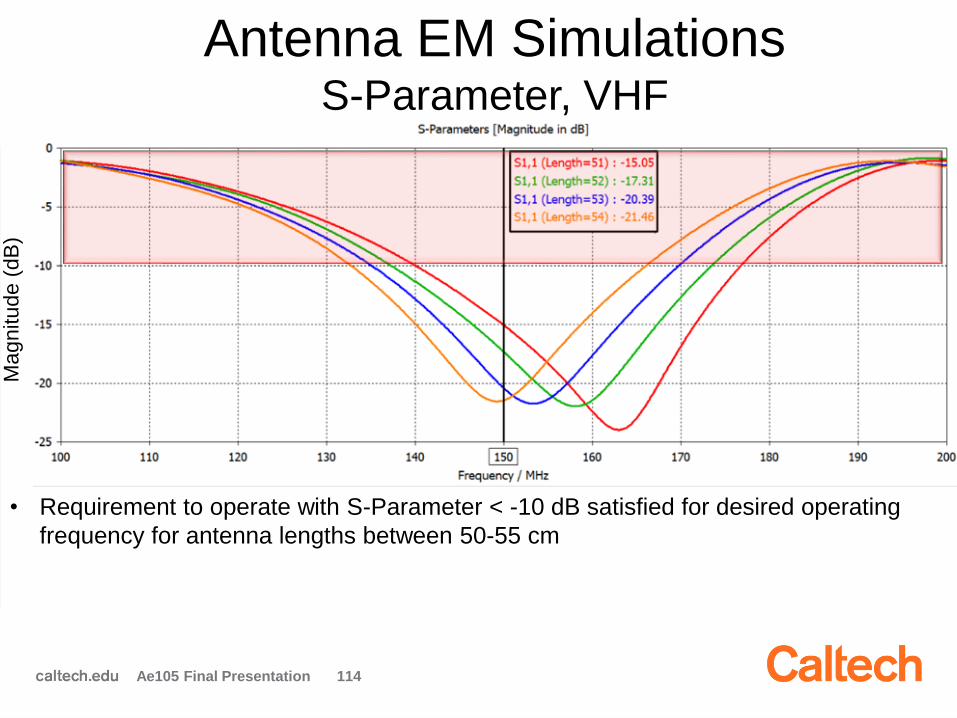
Antenna EM Simulations S-Parameter, VHF
• Requirement to operate with S-Parameter < -10 dB satisfied for desired operating
frequency for antenna lengths between 50-55 cm
Magnitude (
dB
)
Ae105 Final Presentation 114
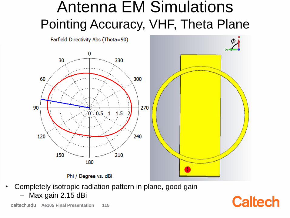
Antenna EM Simulations Pointing Accuracy, VHF, Theta Plane
• Completely isotropic radiation pattern in plane, good gain
‒ Max gain 2.15 dBi
𝜙
Ae105 Final Presentation 115
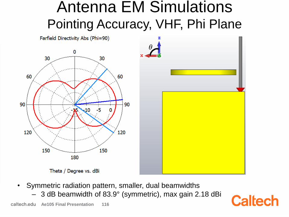
Antenna EM Simulations Pointing Accuracy, VHF, Phi Plane
• Symmetric radiation pattern, smaller, dual beamwidths
‒ 3 dB beamwidth of 83.9° (symmetric), max gain 2.18 dBi
𝜃
Ae105 Final Presentation 116
Antenna EM Simulations Conclusions
VHF: 150 MHz
• Antenna satisfies S-
Parameter requirement
for lengths between
50-55 cm
• Antenna has large
beamwidth, performance
close to isotropic
UHF: 450 MHz
• Best operating lengths
between 17-20 cm, but
does not satisfy S-
Parameter requirement
• Some pointing required to
send/receive data
• Low resolution modeling
due to limitations of
software license; lab EM
testing necessary to
validate results
Ae105 Final Presentation 117

Structural Design
1. Steel tape
spring antenna
(VHF)
2. Aluminum
antenna
mounting filled
with epoxy5. Release
Mechanism6. PCB
4. Vectran
wire
3. Through-hole
on bottom plate
Requirements
1. Antenna must be stiff
and electrically
conductive
2. Antenna must be
insulated from ground
plane and not flattened
3. Antenna must be
connected to coaxial
cable from transceiver
4. Hold antenna in folded
configuration
5. Cut Vectran wire to
deploy
6. Optimize space on
external surface
Ae105 Final Presentation 118
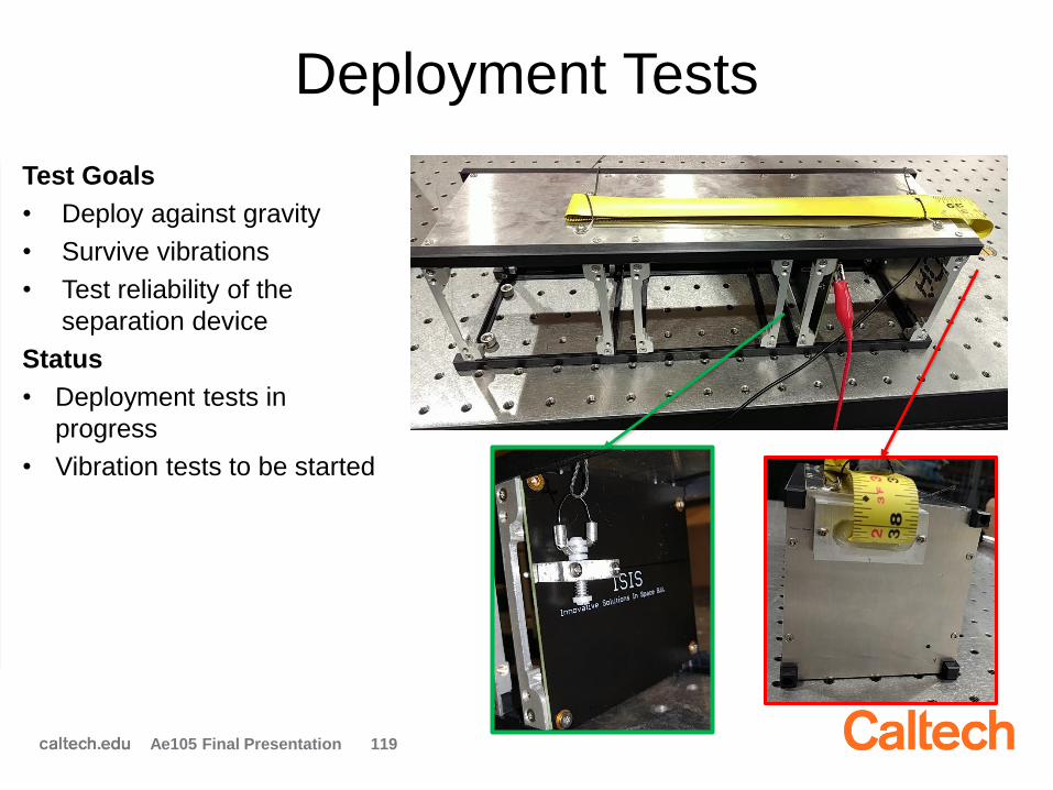
Deployment Tests
Test Goals
• Deploy against gravity
• Survive vibrations
• Test reliability of the
separation device
Status
• Deployment tests in
progress
• Vibration tests to be started
Ae105 Final Presentation 119

Deployment Test
Test Parameters
• 2 A
• 1.2 V
• Deployment time
~22 s
• Antenna successfully deployed
• Test results used to improve second iteration
• Tests in other directions to be performed soon
Direction Number of tests
Horizontal 1
Vertical 2
Ae105 Final Presentation 120
Future Work
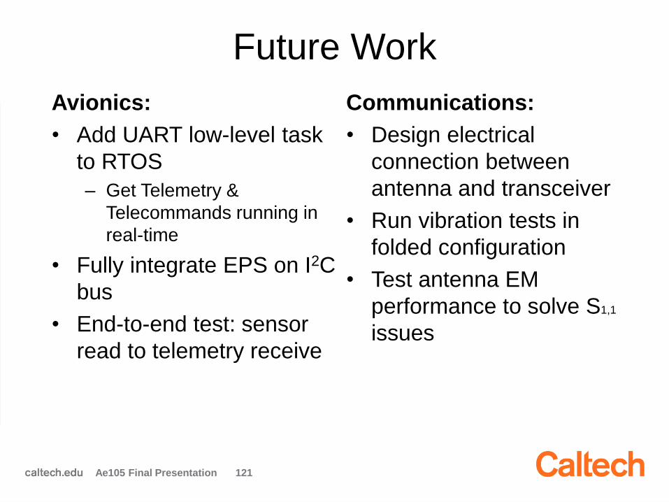
Avionics:
• Add UART low-level task
to RTOS
– Get Telemetry &
Telecommands running in
real-time
• Fully integrate EPS on I2C
bus
• End-to-end test: sensor
read to telemetry receive
Communications:
• Design electrical
connection between
antenna and transceiver
• Run vibration tests in
folded configuration
• Test antenna EM
performance to solve S1,1
issues
Ae105 Final Presentation 121

Conclusions
Avionics:
• Using FlatSat, wrote example
software to retrieve temperature
over I2C with real-time control
– Demonstrated that the program
works
• Protocols defined for Telemetry,
Telecommand, and file transfer
– Data packet design completed
• Demonstrated downlink
communications in the lab. Uplink
telecommand communications
requires debugging
• Beacon list needs to be completed
Communications:
• Downlink data budget completed– More details about debug mode may be
required
– Uplink data budget to be done
• Chosen COTS transceiver
• Completed preliminary EM analyses
• Completed second iteration of
structural design for UHF/VHF
antennas
• Deployment procedure designed
and tested
Ae105 Final Presentation 122

Thank you!
Questions?
Ae105 Final Presentation 123
Outline
2:00 pm: Introduction & Welcome
2:15 pm: Systems Engineering
2:45 pm: Power
3:15 pm: Avionics & Comms
3:45 pm: ADCS
4:15 pm: Structures
Ae105 Final Presentations 134
Attitude Determination and
Control System (ADCS)
Team:
Carmen Amo Alonso
Patrick Hsu
Michael Marshall
Victor Venturi
Mentor: Daniel Pastor
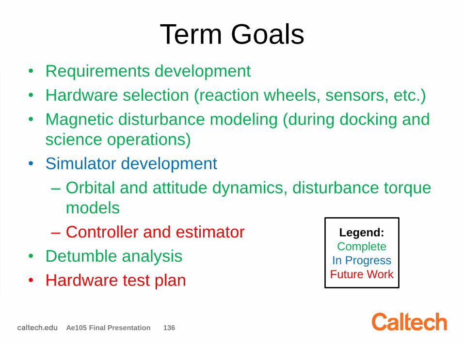
Term Goals• Requirements development
• Hardware selection (reaction wheels, sensors, etc.)
• Magnetic disturbance modeling (during docking and
science operations)
• Simulator development
– Orbital and attitude dynamics, disturbance torque
models
– Controller and estimator
• Detumble analysis
• Hardware test plan
Ae105 Final Presentation 136
Legend:
Complete
In Progress
Future Work
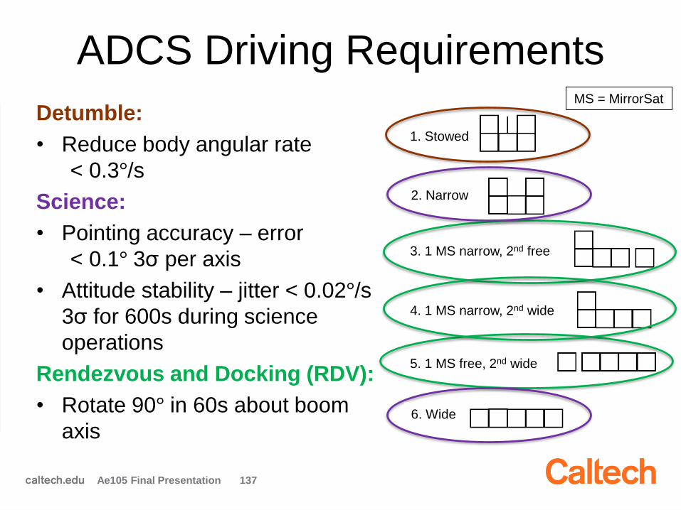
ADCS Driving Requirements
Detumble:
• Reduce body angular rate
< 0.3°/s
Science:
• Pointing accuracy – error
< 0.1° 3σ per axis
• Attitude stability – jitter < 0.02°/s
3σ for 600s during science
operations
Rendezvous and Docking (RDV):
• Rotate 90° in 60s about boom
axis
Ae105 Final Presentation 137
1. Stowed
2. Narrow
3. 1 MS narrow, 2nd free
4. 1 MS narrow, 2nd wide
5. 1 MS free, 2nd wide
6. Wide
MS = MirrorSat
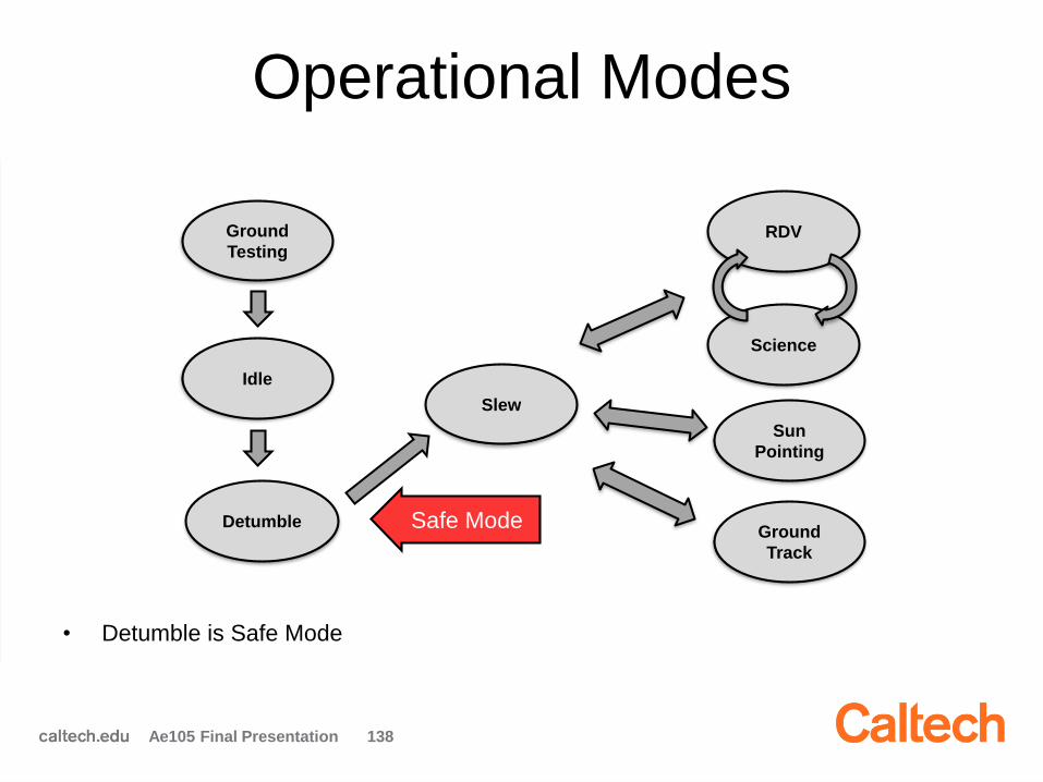
Operational Modes
Ae105 Final Presentation 138
Detumble
Slew
Sun
Pointing
RDV
Science
Ground
Testing
Ground
Track
Idle
Safe Mode
• Detumble is Safe Mode

ADCS Generated Requirements
Ae105 Final Presentation 139
Operational ModeAdditional
RequirementsRelevant Team(s)
Testing• Achieve expected torque values
and directions (ground console
control)
• ADCS – Double check hardware
functionality
Detumble• Body angular rate < 0.3°/s
• Complete this within 4 orbits
• ADCS – Reduce angular rate to be
manageable by reaction wheels
Slew• Bring satellite within 1° of desired
pointing attitude
• Telecomm – Reorient for antenna
• Power – Reorient for charging
• ADCS – Reorient for star pointing
Ground Track• Track ground station to TBD
degrees
• Telecomm – Point antenna to
ground station
Rendezvous and
Docking (RDV)• N/A • N/A
Sun Pointing• Maintain ± 10° of optimal charging
angle
• Power – Allow for most efficient
charging
Science • N/A • N/A
Hardware Selection Criteria
• Meets ADCS requirements (e.g. accuracy during
science operations)
• Want integrated solution that includes all sensors
and actuators (e.g. reaction wheels, star tracker,
computer, etc.)
• Reaction wheels:
– Need to consider different operational modes and
spacecraft configurations
– Capable of rejecting worst-case disturbance
torques and executing required slew maneuver
during RDV
Ae105 Final Presentation 140

Reaction Wheel SizingScience:
• Requirements –
– Accuracy - 0.1° pointing
accuracy
– Drift - 0.02°/s for 600s
• Disturbance Torques –
– Gravity gradient: ~ 10 μN-m
– Magnetic: ~ 1 μN-m
– Drag: ~ 1 μN-m
• Configurations –
RDV:
• Requirements –
– Rotate 90° in 60s
• Slew Maneuver –
• Configurations –
Ae105 Final Presentation 141
+zሶ𝜃 (°/𝑠)
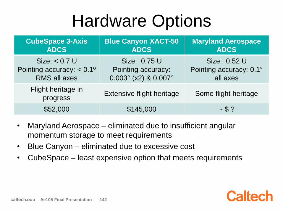
Hardware OptionsCubeSpace 3-Axis
ADCS
Blue Canyon XACT-50
ADCS
Maryland Aerospace
ADCS
Size: < 0.7 U
Pointing accuracy: < 0.1º
RMS all axes
Size: 0.75 U
Pointing accuracy:
0.003° (x2) & 0.007°
Size: 0.52 U
Pointing accuracy: 0.1°
all axes
Flight heritage in
progressExtensive flight heritage Some flight heritage
$52,000 $145,000 ~ $ ?
Ae105 Final Presentation 142
• Maryland Aerospace – eliminated due to insufficient angular
momentum storage to meet requirements
• Blue Canyon – eliminated due to excessive cost
• CubeSpace – least expensive option that meets requirements
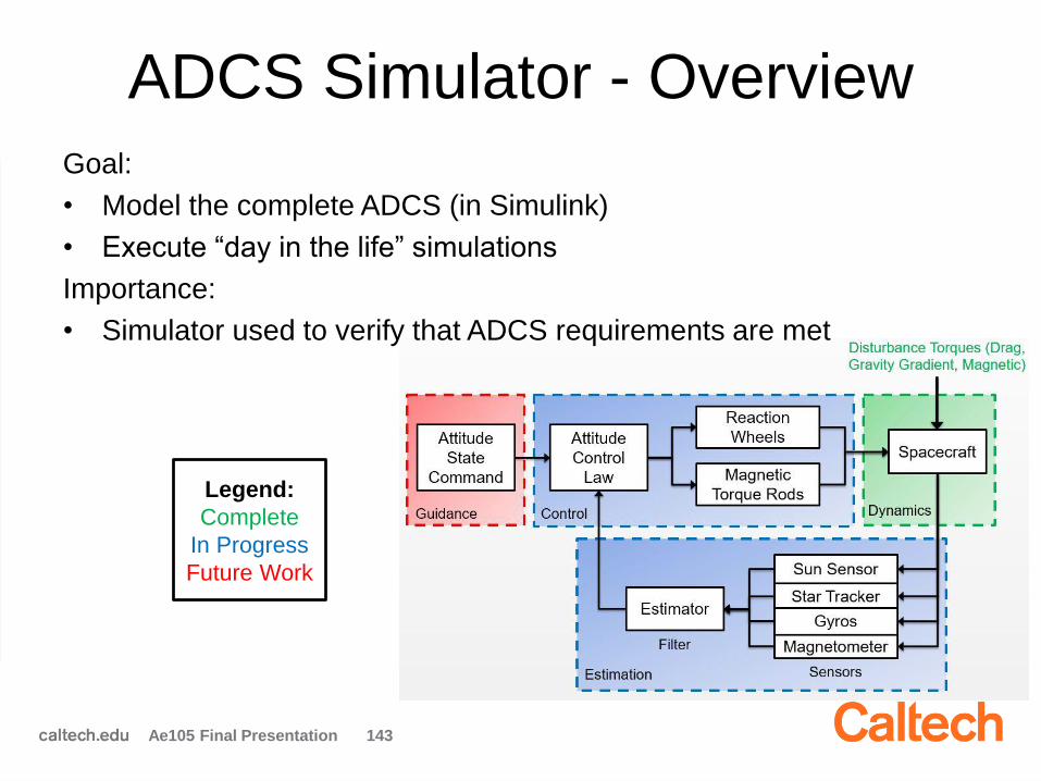
ADCS Simulator - Overview
Ae105 Final Presentation 143
Goal:
• Model the complete ADCS (in Simulink)
• Execute “day in the life” simulations
Importance:
• Simulator used to verify that ADCS requirements are met
Legend:
Complete
In Progress
Future Work
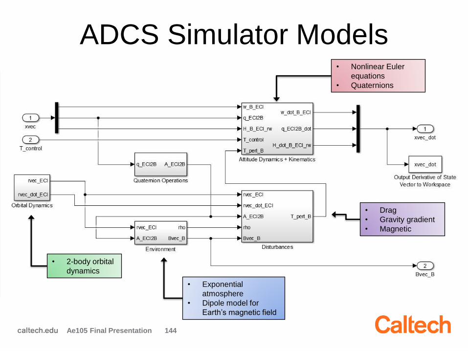
ADCS Simulator Models
Ae105 Final Presentation 144
• Exponential
atmosphere
• Dipole model for
Earth’s magnetic field
• Nonlinear Euler
equations
• Quaternions
• 2-body orbital
dynamics
• Drag
• Gravity gradient
• Magnetic
Disturbance Analysis
Goal: Verify that CubeSpace reaction wheels do not
saturate in one orbit**
Assumptions:
• Inertially pointing (fixed attitude)
• Truth dynamics
• CBE worst-case inertia matrix for stability and pointing
• Magnetic torque rods at max
• Solar radiation pressure (SRP) is negligible
** For an inertially pointed spacecraft, disturbance torques are periodic
with each orbit (to first order)
Ae105 Final Presentation 145
Disturbance Analysis (cont.)
Analysis:
• Monte Carlo simulation with 1,000 runs in five nominal
circular sun-synchronous orbits with altitudes between
500km and 600km
• Random variables - spacecraft attitude, magnetic
moment
• Models cumulative angular momentum buildup in
reaction wheels required to maintain fixed attitude
Ae105 Final Presentation 146

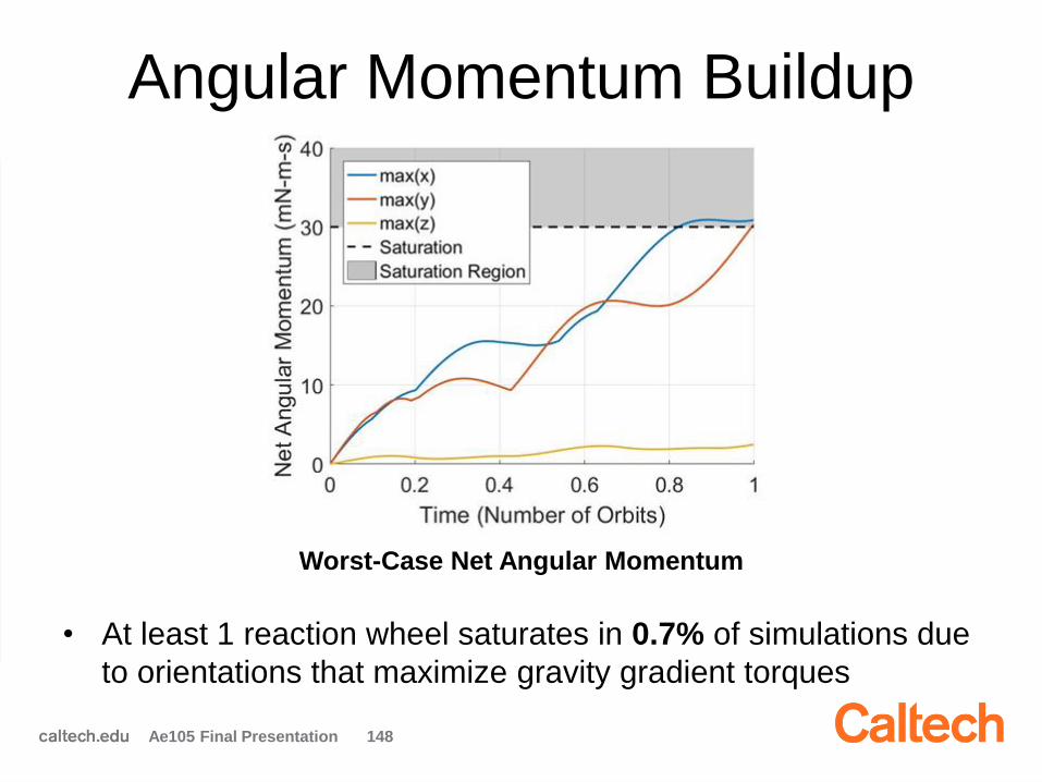
Angular Momentum Buildup
• Nominally, no net angular momentum buildup on spacecraft if
reaction wheels continuously desaturated with torque rods
Ae105 Final Presentation 147
Nominal Angular Momentum
Buildup from Disturbance Torques
Nominal Angular Momentum
Removed by Magnetic Torque Rods
Angular Momentum Buildup
Ae105 Final Presentation 148
Worst-Case Net Angular Momentum
• At least 1 reaction wheel saturates in 0.7% of simulations due
to orientations that maximize gravity gradient torques
Detumbling Analysis
Importance:
• Satellite spinning after ejection from launch vehicle
– Need to inertially point spacecraft to use telescope
Goal:
• Obtain an order of magnitude estimate for detumbling time
Assumptions:
• With ~3 °/s initial tumbling rate, reaction wheels saturate after
removing ~1/2 of the spacecraft’s angular momentum
– Cannot use reaction wheels alone to detumble
• Detumbled when angular velocity < 0.3°/s (star tracker)
• Only gravity gradient and magnetic torques modeled
• Truth dynamics
Ae105 Final Presentation 149
Detumbling Analysis
Ae105 Final Presentation 150
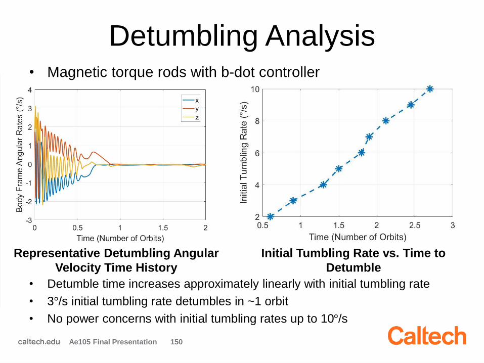
Initial Tumbling Rate vs. Time to
Detumble
Representative Detumbling Angular
Velocity Time History
• Magnetic torque rods with b-dot controller
• Detumble time increases approximately linearly with initial tumbling rate
• 3°/s initial tumbling rate detumbles in ~1 orbit
• No power concerns with initial tumbling rates up to 10°/s
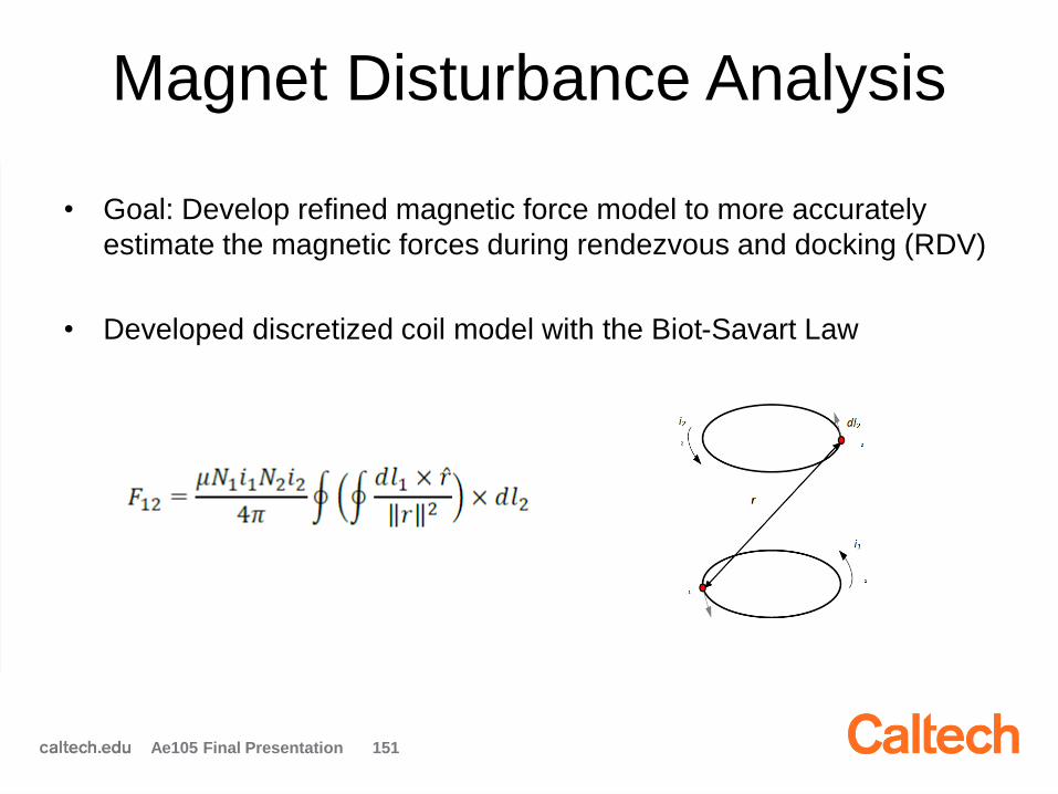
Magnet Disturbance Analysis
Ae105 Final Presentation 151
• Goal: Develop refined magnetic force model to more accurately
estimate the magnetic forces during rendezvous and docking (RDV)
• Developed discretized coil model with the Biot-Savart Law
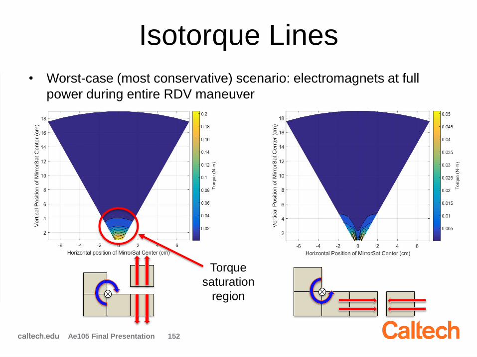
Isotorque Lines
Ae105 Final Presentation 152
• Worst-case (most conservative) scenario: electromagnets at full
power during entire RDV maneuver
Torque
saturation
region
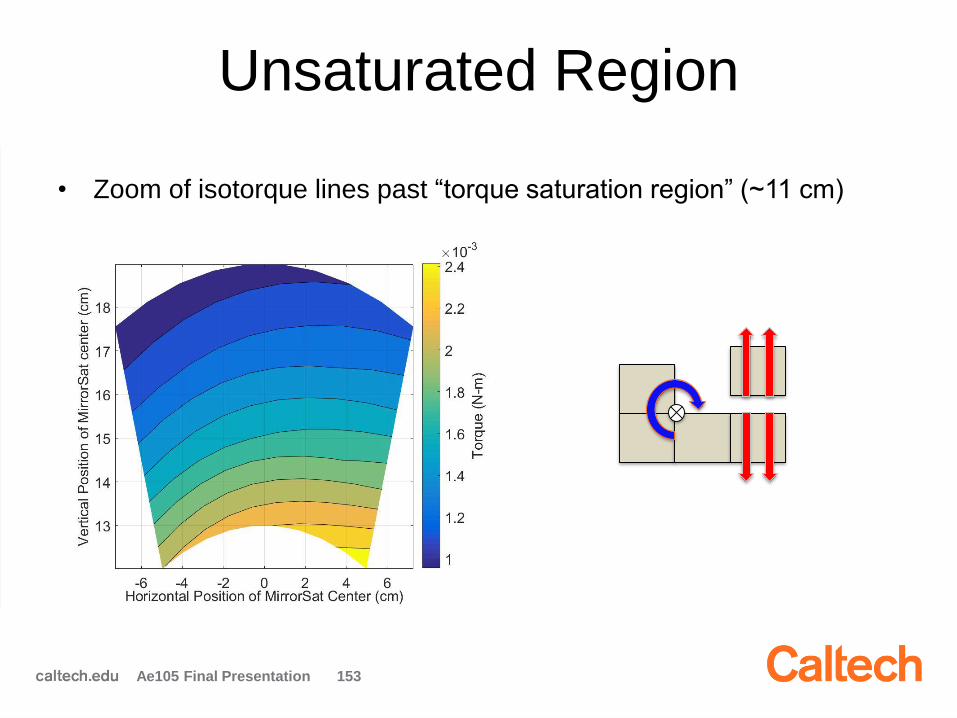
Unsaturated Region
• Zoom of isotorque lines past “torque saturation region” (~11 cm)
Ae105 Final Presentation 153
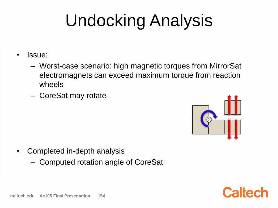
Undocking Analysis
• Issue:
– Worst-case scenario: high magnetic torques from MirrorSat
electromagnets can exceed maximum torque from reaction
wheels
– CoreSat may rotate
• Completed in-depth analysis
– Computed rotation angle of CoreSat
Ae105 Final Presentation 154
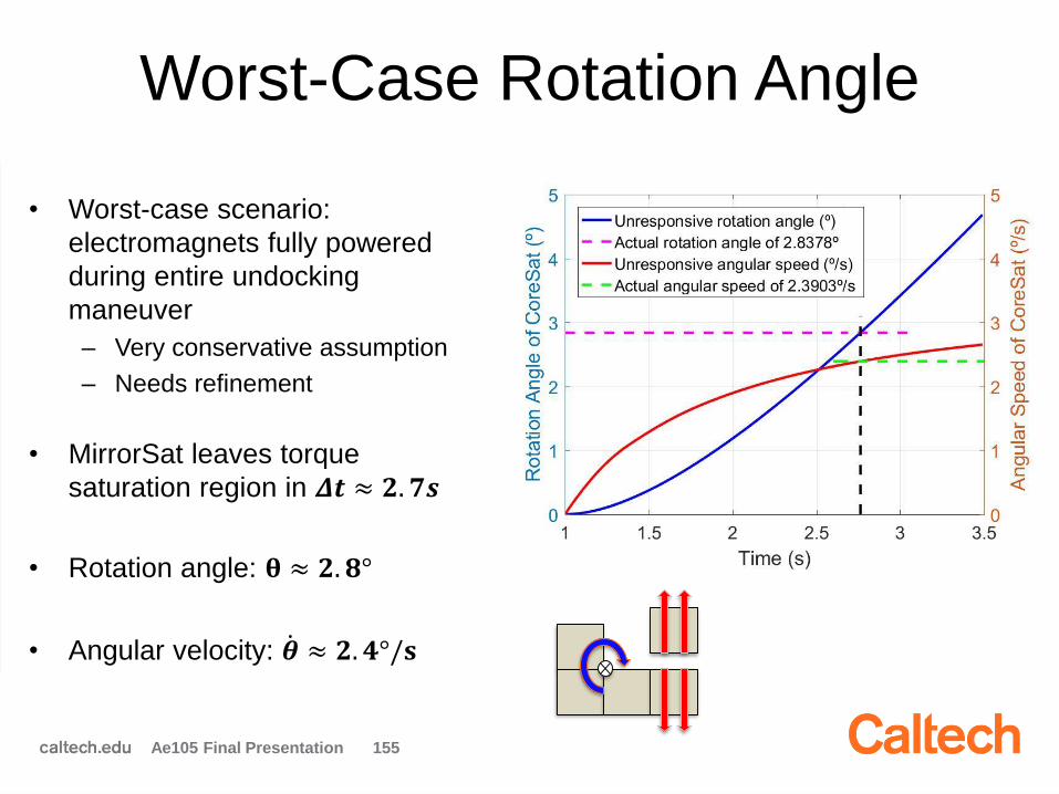
Worst-Case Rotation Angle
• Worst-case scenario:
electromagnets fully powered
during entire undocking
maneuver
– Very conservative assumption
– Needs refinement
• MirrorSat leaves torque
saturation region in 𝜟𝒕 ≈ 𝟐. 𝟕𝒔
• Rotation angle: 𝛉 ≈ 𝟐. 𝟖°
• Angular velocity: ሶ𝜽 ≈ 𝟐. 𝟒°/𝐬
Ae105 Final Presentation 155
ADCS Summary
• Generated ADCS requirements
• Selected hardware
• Developed ADCS simulator
• Completed disturbance and detumbling
analyses
• Created high-fidelity magnetic model and
analyzed forces and torques during RDV
Ae105 Final Presentation 156
Future Work
• Add controller and estimator to simulator
• Conduct detailed ADCS analysis with complete
simulator → requirements verification and
validation (V&V)
• Develop hardware test plans
• ADCS integration, assembly, and testing (IA&T)
Ae105 Final Presentation 157

Ae105 Final Presentation 158
Thank you!
Questions?
Outline
2:00 pm: Introduction & Welcome
2:15 pm: Systems Engineering
2:45 pm: Power
3:15 pm: Avionics & Comms
3:45 pm: ADCS
4:15 pm: Structures
Ae105 Final Presentations 170

Structures Team
Students:
Cole Allen
Ludovic Gil
Stefan Lohaus
Mayra Melendez
Mentor:
Christophe Leclerc

Team Goals
1. Design the CoreSat structure
2. Design the Launch Vehicle Interface
(LVI) plate
3. Select a Hold Down and Release
Mechanism (HDRM)
Ae105 Final Presentation 172

Main Structural Requirements
• Withstand launch environment, with critical
acceleration of 25 g
• Provide accurate positioning of optical systems:
– Mirror boxes
– Boom support
– Docking ports
• Provide mechanical support for all subsystems
• Use CubeSat standards for subsystem
components (96 mm x 96 mm PCBs)
• Provide vertical clearance of 50 mm for MirrorSat
docking maneuvers
Ae105 Final Presentation 173
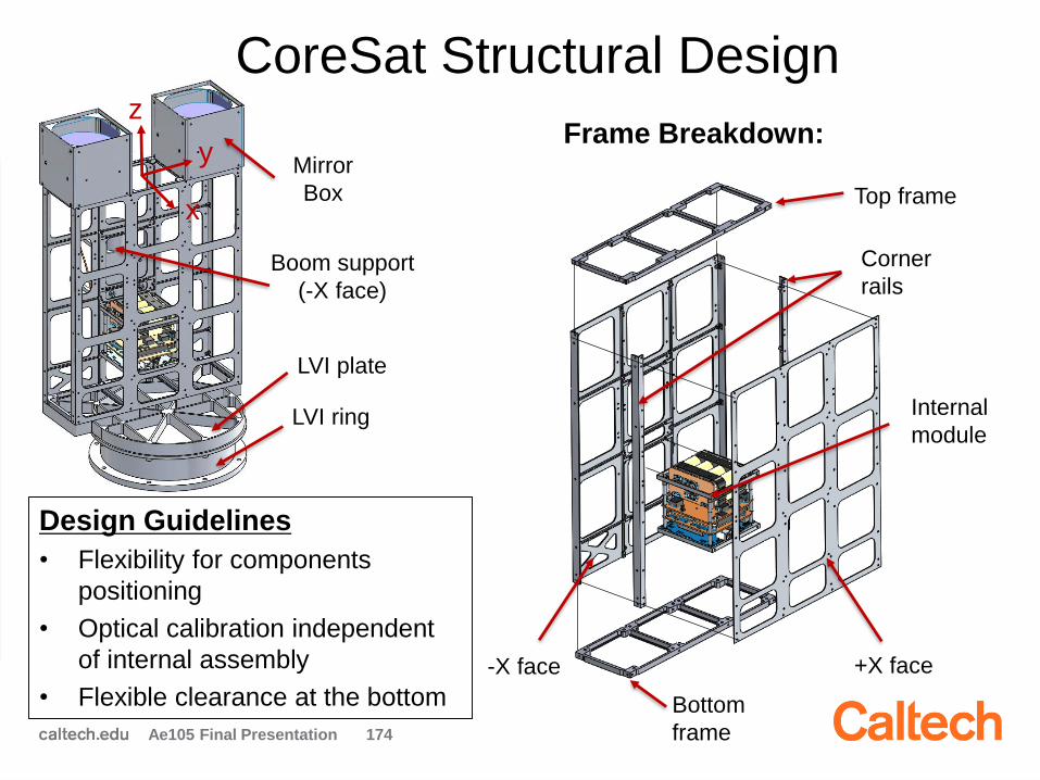
CoreSat Structural Design
Ae105 Final Presentation 174
x
y
z
Mirror
Box
LVI plate
LVI ring
+X face-X face
Top frame
Bottom
frame
Corner
rails
Internal
module
Design Guidelines
• Flexibility for components
positioning
• Optical calibration independent
of internal assembly
• Flexible clearance at the bottom
Boom support
(-X face)
Frame Breakdown:
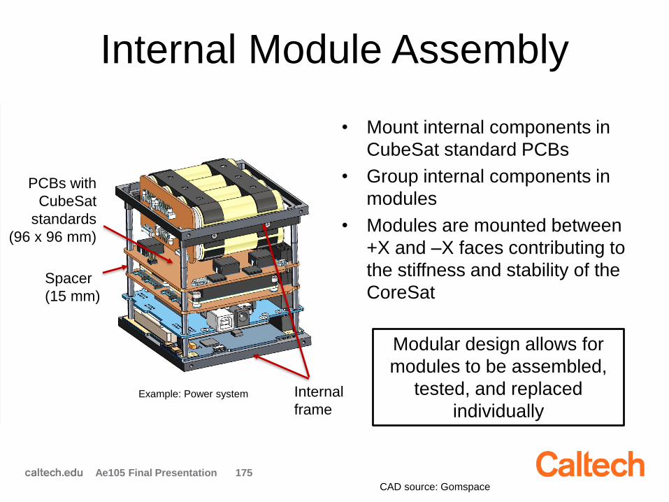
Internal Module Assembly
• Mount internal components in
CubeSat standard PCBs
• Group internal components in
modules
• Modules are mounted between
+X and –X faces contributing to
the stiffness and stability of the
CoreSat
Ae105 Final Presentation 175
Example: Power system
Modular design allows for
modules to be assembled,
tested, and replaced
individually Internal
frame
PCBs with
CubeSat
standards
(96 x 96 mm)
Spacer
(15 mm)
CAD source: Gomspace
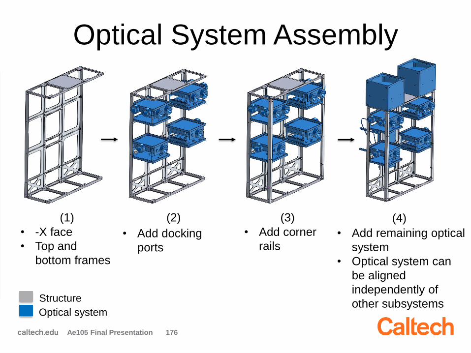
Optical System Assembly
Ae105 Final Presentation 176
• -X face
• Top and
bottom frames
(1) (2) (3) (4)
• Add docking
ports
• Add corner
rails• Add remaining optical
system
• Optical system can
be aligned
independently of
other subsystemsStructure
Optical system

Complete Assembly
Ae105 Final Presentation 177
(8)
• Add solar panels
• Add side
components
• Add LVI plate • Add central
components
• Close +X face
(with solar
panels)
(5) (6) (7) (9)
Structure
Optical system
Other components Modular design allows
for flexibility in assembly
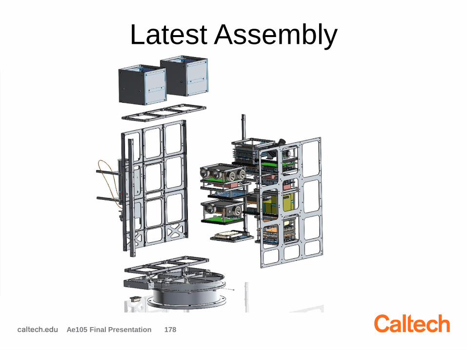
Latest Assembly
Ae105 Final Presentation 178
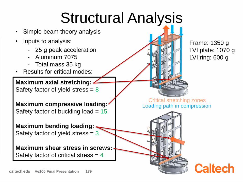
Structural Analysis
Ae105 Final Presentation 179
• Simple beam theory analysis
• Inputs to analysis:
- 25 g peak acceleration
- Aluminum 7075
- Total mass 35 kg
• Results for critical modes:
Critical stretching zones
Maximum axial stretching:
Safety factor of yield stress = 8
Maximum compressive loading:
Safety factor of buckling load = 15
Maximum bending loading:
Safety factor of yield stress = 3
Maximum shear stress in screws:
Safety factor of critical stress = 4
Frame: 1350 g
LVI plate: 1070 g
LVI ring: 600 g
Loading path in compression

Positioning Of Components
Ae105 Final Presentation 180
Motherboards CAD samples: www.cubesatkit.com
CLEARANCE
Docking ports
HDRM PCBs
LVI plate
Antenna release mechanism
Docking ports
Antenna release mechanism
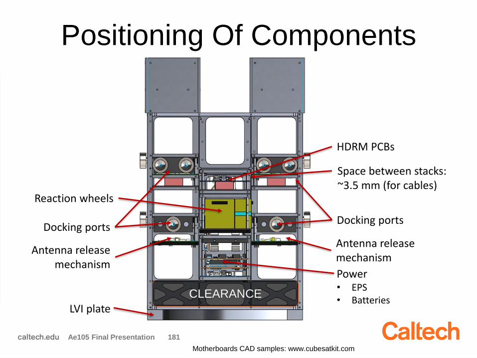
Positioning Of Components
Ae105 Final Presentation 181
Motherboards CAD samples: www.cubesatkit.com
CLEARANCE
Space between stacks: ~3.5 mm (for cables)
Reaction wheels
Power• EPS• Batteries
Docking ports
HDRM PCBs
LVI plate
Antenna release mechanism
Docking ports
Antenna release mechanism
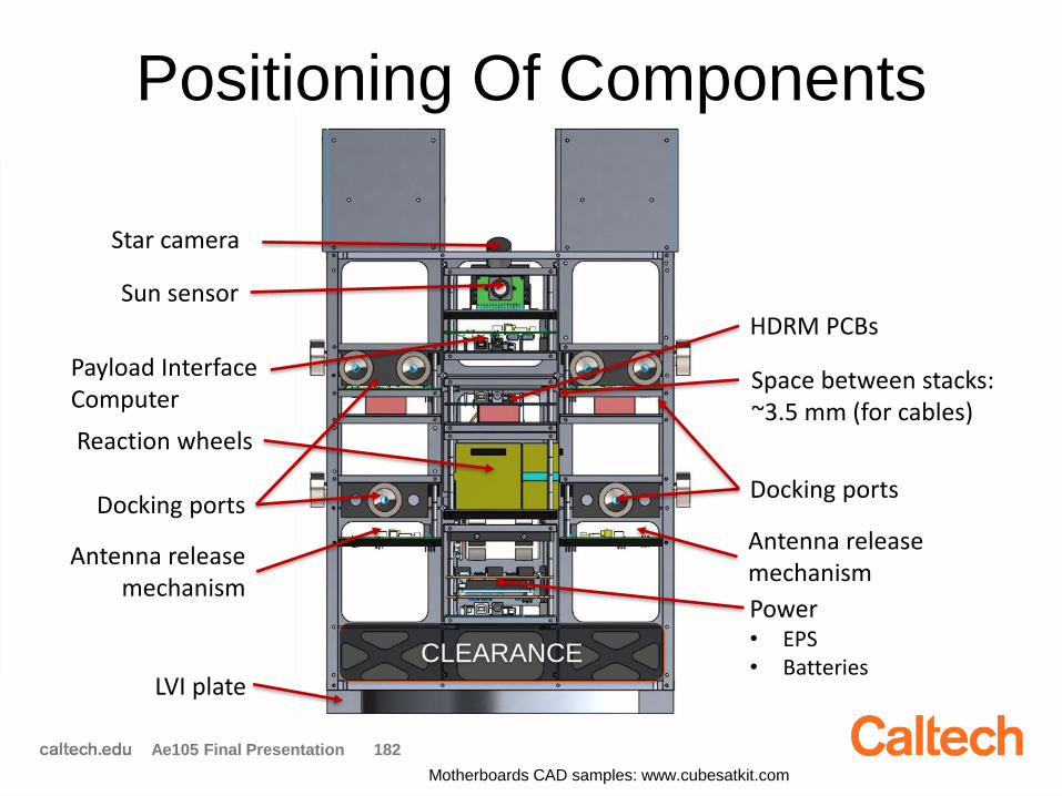
Positioning Of Components
Ae105 Final Presentation 182
Motherboards CAD samples: www.cubesatkit.com
CLEARANCE
Payload Interface Computer
Sun sensor
Star camera
Space between stacks: ~3.5 mm (for cables)
Reaction wheels
Power• EPS• Batteries
Docking ports
HDRM PCBs
LVI plate
Antenna release mechanism
Docking ports
Antenna release mechanism
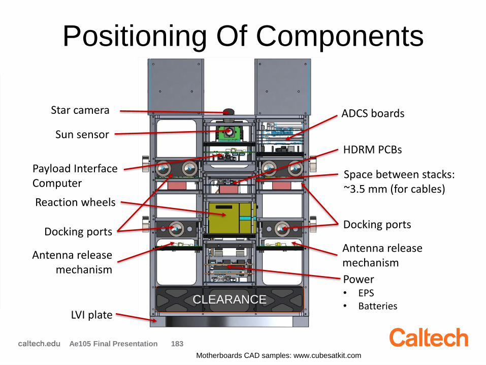
Positioning Of Components
Ae105 Final Presentation 183
Motherboards CAD samples: www.cubesatkit.com
CLEARANCE
ADCS boards
Payload Interface Computer
Sun sensor
Star camera
Space between stacks: ~3.5 mm (for cables)
Reaction wheels
Power• EPS• Batteries
Docking ports
HDRM PCBs
LVI plate
Antenna release mechanism
Docking ports
Antenna release mechanism

Positioning Of Components
Ae105 Final Presentation 184
Radio transceiver
Antenna fixations
CLEARANCE
Motherboards CAD samples: www.cubesatkit.com
ADCS boards
Payload Interface Computer
Sun sensor
Star camera
Space between stacks: ~3.5 mm (for cables)
Reaction wheels
Power• EPS• Batteries
Docking ports
HDRM PCBs
LVI plate
Antenna release mechanism
Docking ports
Antenna release mechanism
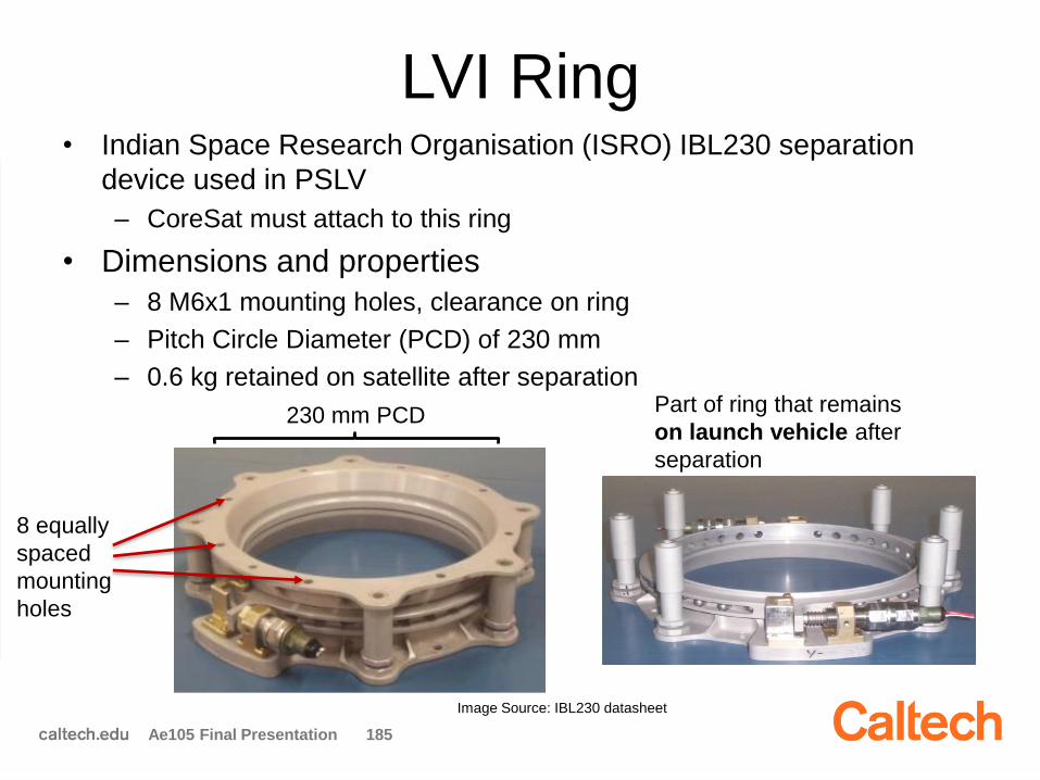
LVI Ring• Indian Space Research Organisation (ISRO) IBL230 separation
device used in PSLV
– CoreSat must attach to this ring
• Dimensions and properties
– 8 M6x1 mounting holes, clearance on ring
– Pitch Circle Diameter (PCD) of 230 mm
– 0.6 kg retained on satellite after separation
Ae105 Final Presentation 185
Image Source: IBL230 datasheet
230 mm PCD
8 equally
spaced
mounting
holes
Part of ring that remains
on launch vehicle after
separation

LVI Plate Requirements and
Considerations• Must withstand peak accelerations of 25 g during launch without
failure (yield)
• Must place center of mass (COM) of AAReST in its stowed
configuration over center of LVI ring
• Should utilize all 8 mounting holes on LVI ring
• Should distribute launch loads evenly
– Concentration of loads in one location could result in failure
Ae105 Final Presentation 186
100 mm
300 mm
CoreSat
Mirror
Sat
Mirror
Sat
230 mmLVI
Ring
Estimated location
of COM

LVI Plate• Mass: 1.07 kg
• Webbing thickness: 5 mm
• Webbing height: 20 mm
Ae105 Final Presentation 187
This face connects to bottom of CoreSat
This face connects to top of LVI ring
Mounting hole locations
for LVI ring
Webbing for structural
support; converge
under COM
Webbing for
structural support
under CoreSat
LVI Plate Structural Analysis
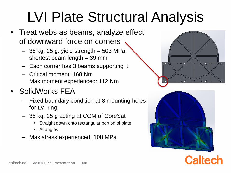
Ae105 Final Presentation 188
• Treat webs as beams, analyze effect
of downward force on corners – 35 kg, 25 g, yield strength = 503 MPa,
shortest beam length = 39 mm
– Each corner has 3 beams supporting it
– Critical moment: 168 Nm
Max moment experienced: 112 Nm
• SolidWorks FEA– Fixed boundary condition at 8 mounting holes
for LVI ring
– 35 kg, 25 g acting at COM of CoreSat• Straight down onto rectangular portion of plate
• At angles
– Max stress experienced: 108 MPa
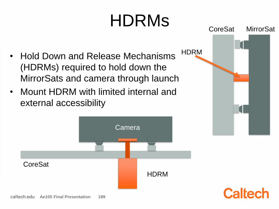
HDRMs
• Hold Down and Release Mechanisms
(HDRMs) required to hold down the
MirrorSats and camera through launch
• Mount HDRM with limited internal and
external accessibility
Ae105 Final Presentation 189
Camera
HDRM
CoreSat
CoreSat MirrorSat
HDRM
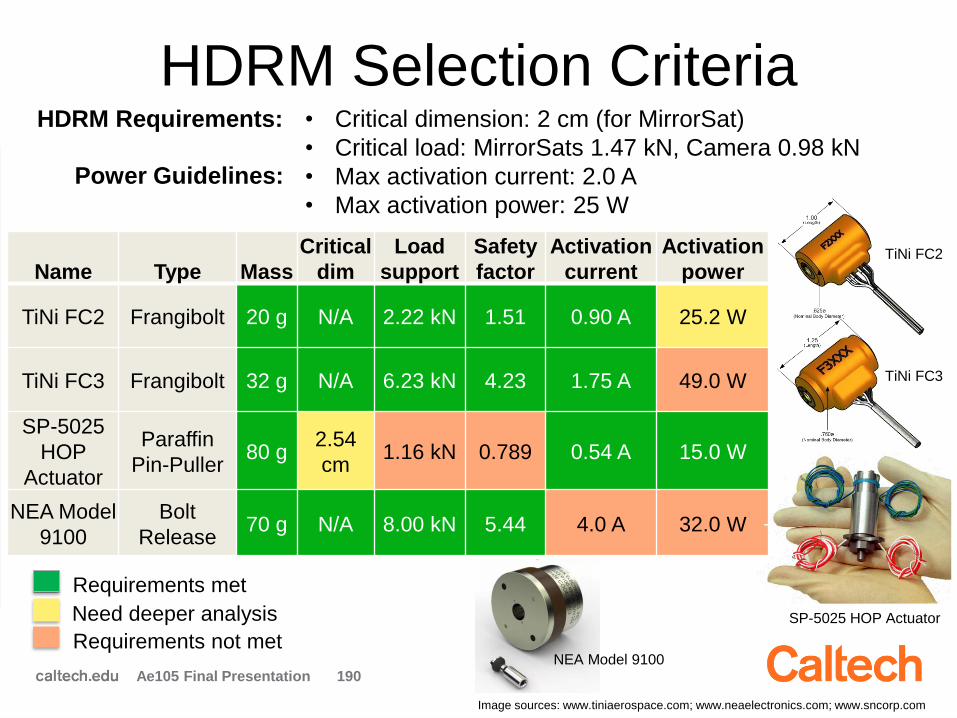
HDRM Selection Criteria
Ae105 Final Presentation 190
Name Type Mass
Critical
dim
Load
support
Safety
factor
Activation
current
Activation
power
TiNi FC2 Frangibolt 20 g N/A 2.22 kN 1.51 0.90 A 25.2 W
TiNi FC3 Frangibolt 32 g N/A 6.23 kN 4.23 1.75 A 49.0 W
SP-5025
HOP
Actuator
Paraffin
Pin-Puller80 g
2.54
cm1.16 kN 0.789 0.54 A 15.0 W
NEA Model
9100
Bolt
Release70 g N/A 8.00 kN 5.44 4.0 A 32.0 W
• Critical dimension: 2 cm (for MirrorSat)
• Critical load: MirrorSats 1.47 kN, Camera 0.98 kN
• Max activation current: 2.0 A
• Max activation power: 25 W
HDRM Requirements:
Requirements met
Need deeper analysis
Requirements not met
Power Guidelines:
NEA Model 9100
SP-5025 HOP Actuator
TiNi FC2
TiNi FC3
Image sources: www.tiniaerospace.com; www.neaelectronics.com; www.sncorp.com
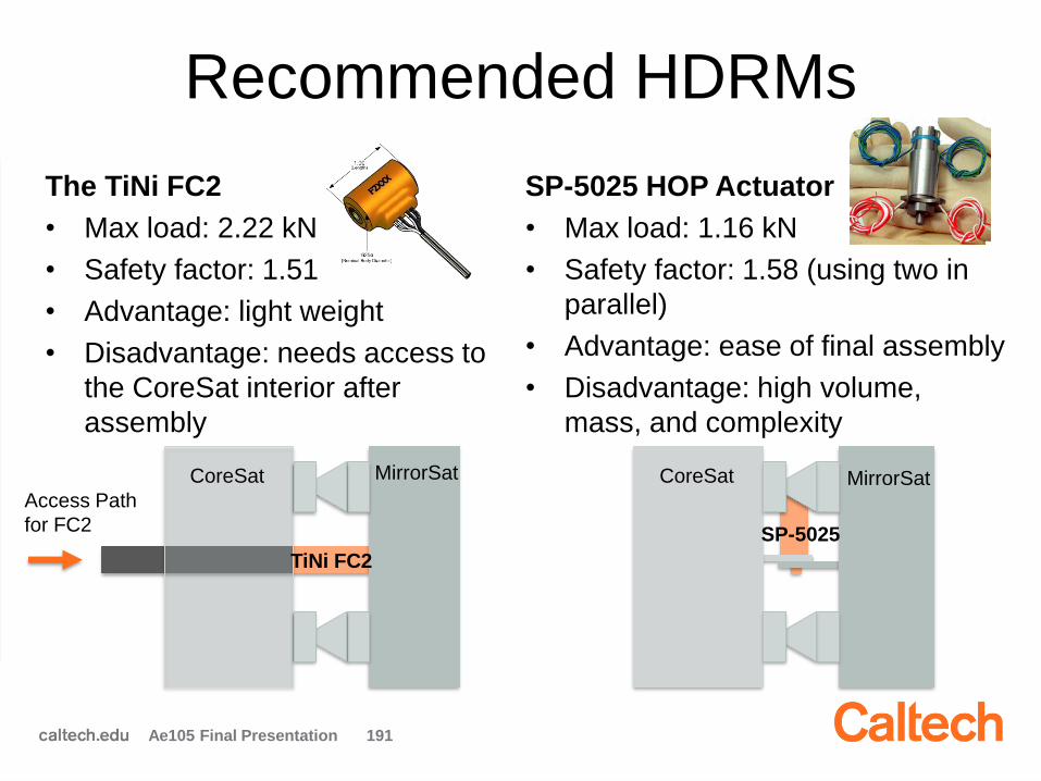
Recommended HDRMs
The TiNi FC2
• Max load: 2.22 kN
• Safety factor: 1.51
• Advantage: light weight
• Disadvantage: needs access to
the CoreSat interior after
assembly
SP-5025 HOP Actuator
• Max load: 1.16 kN
• Safety factor: 1.58 (using two in
parallel)
• Advantage: ease of final assembly
• Disadvantage: high volume,
mass, and complexity
Ae105 Final Presentation 191
TiNi FC2
MirrorSatCoreSat
Access Path
for FC2
MirrorSatCoreSat
SP-5025
Summary
Ae105 Final Presentation 192
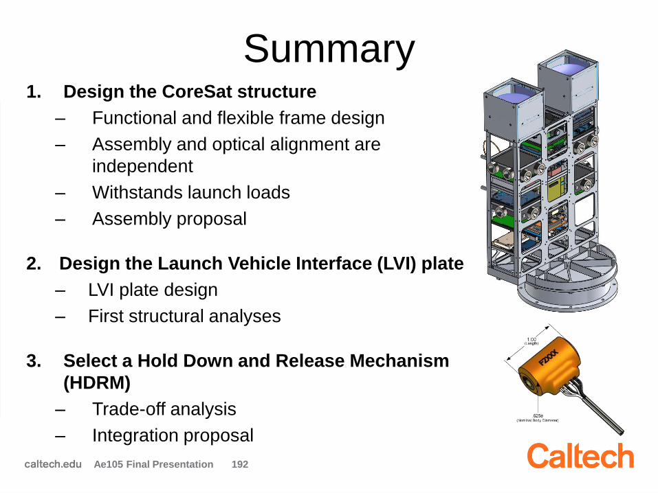
1. Design the CoreSat structure
– Functional and flexible frame design
– Assembly and optical alignment are
independent
– Withstands launch loads
– Assembly proposal
2. Design the Launch Vehicle Interface (LVI) plate
– LVI plate design
– First structural analyses
3. Select a Hold Down and Release Mechanism
(HDRM)
– Trade-off analysis
– Integration proposal

Future Work
• Finalize design depending on final choice
of components
• Design fixation for selected HDRM
• Build, assemble, and test a prototype
• Improve structural analyses for the LVI
plate and the frame
Ae105 Final Presentation 193
Questions
Ae105 Final Presentation 194