Embed Size (px)
Citation preview

24
Tenderer Chief Engineer
2.00 GENERAL CONDITIONS OF CONTRACT
2.01.00 Definitions
2.01.01 In the contract (as hereinafter defined) the following words and expressions shall
have the meaning hereby assigned to them except where the contract otherwise
requires.
2.01.02 The “Owner/Client” shall mean the Corporation/Board/Department/Person for
whom the work is being arranged.
2.01.03 The ACCEPTING AUTHORITY shall mean the Accepting Officer/Firm with
whom the Contractor executes the Agreement and this shall be mentioned in
NIT.
2.01.04 The “Contractor” shall mean person or persons, firm or company whose tender
has been accepted and includes the Contractor’s legal representatives, successors
and permitted assigns.
2.01.05 “Tender” shall mean the tender submitted by the Contractor for acceptance before
the ACCEPTING AUTHORITY.
2.01.06 The “work” shall mean and include all works to be executed in accordance with
the contract or part thereof as the case may be and shall include all extras,
additional, altered or substituted works required for the purpose of the contract.
2.01.07 The “Contract” shall mean the agreement between ACCEPTING AUTHORITY
and the Contractors for the execution of the work including therein all documents
such as the Notice Inviting Tender, Tender Form, General Conditions of
Contract, Special Conditions of Contract ,Technical Specification, Specification
and Schedule of Quantities, Letter of Acceptance, Agreed variation if any,
drawings, work orders, and / or any other / correspondences or negotiations, etc.
2.01.08 “Specifications” shall mean all directions, various technical specifications,
provisions and requirements attached to the contract which pertain to the method
and manner of performing the work, and the materials to be furnished under the
contract for the work as may be amplified or modified by ACCEPTING
AUTHORITY/Consultant, drawings for the performance of the contract in order
to provide the unforeseen conditions or in the best interest of the work. It shall
also include the latest revised version of the relevant B.I.S. specification and
other relevant codes.
2.01.09 “Site” shall mean the land allotted by the Owner/Client under in or through
which the work is to be carried out.
2.01.10 “Letter of Acceptance/Award of Work” shall mean an intimation by letter,
telegram, telex or fax to the tenderer that the tender has been accepted in
accordance with the provisions contained therein.

25
Tenderer Chief Engineer
2.01.11 “Engineer” shall mean the Engineering Personnel representing ACCEPTING
AUTHORITY/Consultant and entrusted with work of supervision of work at the
site.
2.01.12 “Contract sum/price” shall mean the total sum referred to in the schedule of
quantities and rates and accepted by ACCEPTING AUTHORITY.
2.01.13 The ‘Probable Amount of Contract’ (PAC) shall mean the Estimated
amount/Tendered amount of the work.
2.01.14 The “Payment Authority” shall mean the Officer/Firm who makes payments of
the bills for the work done and this shall be mentioned in NIT.
2.02.00 SITE
2.02.01 Location and details of site are specified in NIT.
2.02.02. Entry into the project area will be restricted. Passes and permits will have to be
obtained from Owners for entry of all persons and vehicles into the project area.
During working, the Contractor shall provide barricades and screens and working
place shall be isolated from other places. Working place shall be visible from
other areas.
2.03.00 SCOPE OF WORK
2.03.01 The scope of work is described in the NIT.
2.03.02 The scope of work further includes variation or modification of design, quantity
or quality of work, addition, omissions or substitution of any work, under the
instruction of ACCEPTING AUTHORITY/Consultant. Such instructions shall be
complied forthwith.
2.03.03 The Contractor shall provide all necessary labour, materials, equipments and
management and supervisory personnel to complete the works provided under
this contract in time.
2.04.00 ASSIGNMENT AND SUB-CONTRACTING
2.04.01 ASSIGNMENT
The Contractor shall not assign the contract or any part thereof or any benefit or
interest therein or thereunder without the written permission of ACCEPTING
AUTHORITY; not shall transfers be made by Power of Attorney authorizing
others to carry out the work or receive payment on behalf of the tenderer.

26
Tenderer Chief Engineer
2.04.02 SUB-CONTRACTING
The contractor shall as soon as practicable, after signing the contract, notify to
the Engineer-in-Charge, in writing, the names of the subcontractors proposed for
the work.
The Contractor shall be fully responsible to ACCEPTING AUTHORITY for the
acts and omissions of his subcontractors and of persons directly or indirectly
employed by them, as he is for the acts and omissions of persons employed by
him.
Nothing contained in the contractual documents shall create any contractual
relation between any subcontractor and the ACCEPTING AUTHORITY.
Subcontracting shall be limited to NOT exceeding 40% of the total amount of
contract. In case of specialised nature of work requiring very high quality
stipulations, such works shall not be subcontracted unless:-
a) The subcontractor firm has sufficient expertise, equipment/plant back up and
experience in the similar nature of work.
b) The subcontractor firm has sufficient financial background. The firm should
have atleast 20% of the value of work to be sublet as net assets.
c) The subcontractor firm has a track record of completing the works on time and to
the quality stipulations.
d) The subcontractor firm has not run into litigation/ arbitration in the past three
years with the clients.
In no event can any delay or unsatisfactory work conducted by the subcontractor
can either be accepted or can be contractor adduce such delay or unsatisfactory
work attributable to subletting of work. The main contractor shall be fully
responsible for the contract and Management of subcontractors.
2.05.00 DRAWING
2.05.01 ISSUE OF DRAWINGS
Drawings approved for construction will be issued to the Contractor
progressively during the contract period and the Contractor shall arrange for the
execution of the works and the procurement of materials accordingly. The
Contractor shall give adequate notice in writing to ACCEPTING AUTHORITY
or his representative of any further drawings or specifications that may be
required for the execution of the works or otherwise under the contract.

27
Tenderer Chief Engineer
2.05.02 COPIES OF DRAWINGS TO BE KEPT AT SITE
One copy of the drawings furnished to the Contractor as aforesaid shall be kept at
the site and the same shall at all reasonable times be available for inspection and
use by ACCEPTING AUTHORITY or their representative and by any other
person authorised by ACCEPTING AUTHORITY in writing.
2.05.03 ISSUE OF FURTHER DRAWINGS AND INSTRUCTIONS
ACCEPTING AUTHORITY shall have full power and authority to supply to the
Contractor from time to time through his representative, during the progress of
the works such further drawings and instructions as shall be necessary for the
purpose of proper and adequate execution and maintenance of the works and the
Contractor shall carry out and be bound by the same.
2.05.04 OWNERSHIP OF DRAWINGS
All drawings supplied to the Contractor are deemed to be the property of
ACCEPTING AUTHORITY. The Contractor should not divulge or use, expect
for the purpose of this contract, any information contained in the drawings.
2.05.05 EXECUTION AS PER DRAWINGS
The Contractor must not vary or deviate from the drawings in any respect while
executing the work or executing any extra work of any kind whatsoever unless
authorised by ACCEPTING AUTHORITY.
2.05.06 PLANS AND DRAWINGS TO BE SUBMITTED BY CONTRACTOR
The Contractor shall submit the following information in triplicate to
ACCEPTING AUTHORITY for approval within the time stipulated: each item
below:-
a)A general tentative layout plan of construction plant and equipments for the
execution of work within 7 days from the date of receipt of work order.
b)Drawings or prints showing the location of major plants and other facilities
which he proposes to put up at the site, including any changes in the general
layout, at least 7 days prior to the commencement of the respective work.
Layout and details of temporary works that the Contractor wants to carry out to
fulfil his obligation under the contract. Within 15 days ACCEPTING
AUTHORITY will give their approval/comments sufficient to proceed with the
work or objections/instructions to the Contractor based on which the drawings
shall be revised and submitted again for approval by the Contractor.

28
Tenderer Chief Engineer
All these plans and drawings submitted by the Contractor and approved by
ACCEPTING AUTHORITY shall become part of the contract.
2.05.07 ROYALTIES AND PATENT RIGHTS
All royalties or other sums payable in respect of the supply and use in carrying
out the work as desired by or referred to in the schedule of quantities of any
patented articles, process or inventions shall be deemed to have been included in
the contract sum and the Contractor shall indemnify ACCEPTING
AUTHORITY from and against all claims, proceedings, damages, costs and
expenses which may be brought or made against ACCEPTING AUTHORITY or
to which he may be put by reason of the Contractor infringing or being held to
have infringed any patent rights in relation to any such articles, process and
inventions.
2.06.00 GENERAL OBLIGATIONS
2.06.01 INSPECTION OF SITE ETC. BEFORE SUBMISSION OF TENDER
The Contractor shall inspect and examine the site and its surroundings, and shall
satisfy himself before submitting his tender, as to the nature of the ground, form
and nature of the site, the quantities and nature of work and materials and its
availability required for the completion of the works, the means of access to the
site, the local labour conditions, the accommodation he may requires and in
general shall obtain all necessary information as to the risks, contingencies and
other circumstances which may influence or affect his tender. He must go
through all the drawings, specifications and other tender documents. Any further
clarifications in the drawings and documents can be had from ACCEPTING
AUTHORITY at the above mentioned address.
2.06.02 SUFFICIENCY OF TENDER
The Contractor shall be deemed to have satisfied himself before tendering as to
the correctness and sufficiency of his tender for the works and of the rates and
prices stated in the priced bill of quantities and the schedule of rates and prices, if
any, with tender rates and prices shall cover all is obligations under the contract
and all matters and things necessary for the proper completion and maintenance
of the work.
2.06.03 DISCREPANCY OR ERROR IN TENDER DOCUMENT
Should the Contractor notice any discrepancy or error in the tender document, in
the statement made, or quantities or units shown against items, he shall
immediately bring to the notice of ACCEPTING AUTHORITY and obtain the
clarification before submitting the tender. The tender shall be based on such
clarifications received and shall be recorded as such in the covering letter to the
tender, failing which ACCEPTING AUTHORITY shall have the right to ask the

29
Tenderer Chief Engineer
Contractor to execute the work according to the corrected statement made or
quantities or units shown in the tender, without any compensation; when the
same has come to the notice of the ACCEPTING AUTHORITY.
2.06.04 RATES QUOTED FOR FINISHED WORK
The rates quoted in the tender by the Contractor must be for the finished work as
per the drawings and specifications.
2.06.05 LOCATION OF WORK
Unless specifically mentioned in the item, the work described there-in may be at
any location or elevation.
2.06.06 FIRM PERIOD
The tender shall remain open for acceptance for a period of 4 months from the
date of opening of the tender. If any tenderer withdraws his tender before the
said period or makes any modifications in terms and conditions of the tender,
then ACCEPTING AUTHORITY has the liberty to forfeit the said Earnest
Money Deposit.
2.06.07 COMMENCEMENT OF WORK
The Contractor shall commence the work at site, within 7 days from the date of
receipt of letter of award of work or handing over of the site whichever is later
and shall proceed with the same with due expedition.
2.06.08 PROGRAMME OF WORK
Soon after the award of contract, the Contractor shall submit to ACCEPTING
AUTHORITY or to their representative for his approval a programme to match
with the planned completion of the whole job showing the order of procedure
and method in which he proposes to carry out the works and shall whenever
required by ACCEPTING AUTHORITY or ACCEPTING AUTHORITY's
representative, furnish further detailed programme and particulars in writing of
the Contractor’s arrangements for carrying out the works and of the
constructional plant and temporary works, which Contractor intends to supply
use or construct as the case may be. The Contractor shall draw a detailed
schedule of programme in the form of PERTCHART and a bar Chart on whole
work, within one week of award of work and submit to ACCEPTING
AUTHORITY for their approval. The submission to and approval, if any, by
ACCEPTING AUTHORITY or its representative of such programmes or
particulars shall not relieve the Contractor of any of his duties or representatives
under the contract.
2.06.09 CONTRACTOR’S EMPLOYEES

30
Tenderer Chief Engineer
The Contractors shall provide and employ sufficient qualified personnel at site in
connection with the project management.
Only such technical assistants as are skilled and experienced in their respective
fields and such-agents, foreman and leading hands as are competent to give
proper supervision to the work they are required to supervise and,
Such skilled, semi-skilled and un-skilled labour as is necessary for the proper and
timely execution and maintenance of works.
2.06.10 REMOVAL OF WORKMEN
ACCEPTING AUTHORITY shall be at liberty to object to and require the
Contractor to remove forthwith from the works any person employed by the
Contractor in or about the execution or maintenance of the works who in the
opinion of ACCEPTING AUTHORITY misconduct himself or is incompetent or
negligent in the proper performance of his duties or whose employment is
otherwise considered by ACCEPTING AUTHORITY to be undesirable and such
person shall be replaced by the Contractor without delay by a competent
substitute approved by ACCEPTING AUTHORITY.
2.06.11 COMMUNICATIONS TO BE IN WRITING
All references, communications, correspondences made by ACCEPTING
AUTHORITY, ACCEPTING AUTHORITY's representative or the Contractor
concerning the works shall be in writing and no reference, communication, or
complaint which is not in writing, shall be recognised.
2.06.12 OCCUPATION AND USE OF LAND
No land, building belonging to or in the possession of the Owner/Client/
Consultant shall be occupied by the Contractor. The Contractor shall not use, or
allow to be used, the site for any purpose other than that for executing the works.
2.06.13 CONTRACTOR’S STORE AND SITE OFFICE
Any site-shed, proposed to be temporarily constructed by the Contractor for his
office work, storage of materials, etc. shall conform to the standard sketch, or to
the plan approved by ACCEPTING AUTHORITY. Permission for the
construction of such sheds shall be obtained in writing. Suitable area in the site
of work shall be allowed to the Contractor free of cost for constructing company
structures for storing his tools and plants, materials site office and cement
Godown. However, the structure will be provided by him at his own expense
and he will be solely responsible for guarding his property with requisite
insurance against theft, fire, etc. The Contractor however will have to dismantle
the sheds and vacate the land of all debris, etc. at his own expense after
completion of work.

31
Tenderer Chief Engineer
2.06.14 MATERIALS, TOOLS AND PLANT
All materials required for the execution of the works other than those mentioned
in the Notice Inviting Tender shall be supplied by the Contractor. Materials so
supplied shall have the approval of ACCEPTING AUTHORITY before using on
the works. All the rejected materials shall be removed at once from the site of
work at the Contractor’s own cost.
2.06.15 TOLLAGES, ETC.
The Contractor shall pay all tollages and other royalties, rent and other payments
or compensations, if any, for getting stone, gravel, sand, clay and all other
materials required for the works.
2.06.16 SETTING OUT
The Contractor shall be responsible for the true and proper setting out of the
works and for the correctness of the position, levels, dimensions and alignment
of all parts of the works and for the provision of all necessary instruments,
appliances and labour in connection therewith. If at any time during the progress
of the works any error shall appear or arise in the position, level, dimensions or
alignment of any part of the works, the Contractor on being required to do so by
ACCEPTING AUTHORITY or ACCEPTING AUTHORITY’s representative,
shall at his own cost rectify such error to the satisfaction of ACCEPTING
AUTHORITY or his representative. The checking of any setting out or of any
way relieve the Contractor from the responsibility of true and proper setting out
of the works. The Contractor shall provide all necessary instruments, appliances
and labour required by ACCEPTING AUTHORITY or his representative for
checking if any, of the setting out. The Contractor shall carefully protect and
observe all bench marks, site levels, pegs and other things used in setting out the
works. The rates quoted for the work shall also include the cost of reference and
level pillars and other dismantling, when no longer required.
2.06.17 DAMAGE TO PERSONS AND PROPERTY
The Contractor shall identify and keep indemnified ACCEPTING AUTHORITY
against all losses and claims for injuries or damages to any person or property
whatsoever which may arise out of or in consequence of the construction and
maintenance of works and against all claims, demands proceedings, damages,
costs, charges, expenses, whatsoever in respect thereof in relation thereto.
2.06.18 CO-OPERATION WITH OTHER AGENCIES
The Contractor shall co-operate with the work of other agencies or Contractors
that may be employed or engaged by ACCEPTING
AUTHORITY/CONSULTANT and as far as it relates to the Contractor’s work.

32
Tenderer Chief Engineer
The sequence of work shall be so arranged that the work of other agencies are
also in progress simultaneously.
2.06.19 BARRICADING AROUND EXCAVATED TRENCHES, ETC.
The Contractor shall at his own cost provide around excavation, temporary
barricading with bellies and bamboo with warning signals during day and night
and shall maintain it so long as the trenches are not filled up. Similar barricades
shall also be provided at all dismantling work, erection of structural, sheeting
work, etc. No extra claim shall be entertained for providing, maintaining and
removing such barricades.
2.06.20 FABRICATION DRAWINGS
Contractor shall prepare at his own cost all fabrication drawings of all structural
steel works and bar bending schedule for R.C.C. works and submit them to
ACCEPTING AUTHORITY for their approval at least before 15 days of
commencing the fabrication. All the details like sizes, capacities, dimensions,
arrangement of fabrication, etc. should be clearly indicated on these drawings.
2.06.21 PROTECTION OF UNDERGROUND SERVICES
The Contractor must take precautionary measures to protect the underground and
other services lines viz. Cables, water and sewer lines, etc. and observe any
specific instructions which may be given in this regard by ACCEPTING
AUTHORITY.
2.06.22 DEWATERING TRENCHES AND PITS
The tendered rates shall always be deemed to have taken into account the cost of
removal of silt and materials that may slip in the trenches and pits and
dewatering the trenches or pits of water accumulated or collected through
seepage or subsoil water or rain water. The Contractor shall in no case be
entitled to claim any extra amount for the above work. The Contractor shall
remain prepared with necessary pumps and equipment for dewatering the
trenches or pits so as to avoid unnecessary delay and possible damage to the
property, etc.
2.06.23 WORK IN OR AROUND OPERATING PLANT OR OFFICES ETC.
Where the work is being carried out in or around an operating plant where the
plant must run uninterrupted, the Contractor shall work only at specified place
and times as mutually arranged between the Contractor and ACCEPTING
AUTHORITY. Similar arrangement must be made while executing works inside
the offices, buildings, etc. without causing disturbance to the office work. For
this the work may be required to be done during off-hours and Sundays. No
extra will be allowed beyond the rates quoted for doing work in the manner
described above.

33
Tenderer Chief Engineer
2.06.24 WORK IN SHIFTS AND ON OFF-DAYS
The Contractor shall work in one or more shifts as also on Sundays and off days
to complete the work on time, if so required by ACCEPTING AUTHORITY for
which ACCEPTING AUTHORITY shall not be liable to pay any extra. If
instructed by ACCEPTING AUTHORITY, the Contractor should carry out the
work in the night also.
2.06.25 SITE ORDER BOOK AND CEMENT REGISTER
A site order book must be maintained and always be available at site to record
the instructions by ACCEPTING AUTHORITY or their representative. The
Contractor must see that the instructions noted therein are properly carried out.
A register showing the stock, receipts, daily issue/consumption of cement and
balance quantity available etc. should be maintained at site and made available
on demand by the ACCEPTING AUTHORITY.
2.06.26 DELAY IN OBTAINING MATERIALS SUPPLIED BY ACCEPTING
AUTHORITY
If ACCEPTING AUTHORITY has undertaken to supply any material specified
in the special conditions at rates and conditions cited therein, the Contractor shall
keep himself in touch with day-to-day position regarding the supply of materials
from ACCEPTING AUTHORITY and so adjust the progress of the works that
labour may not remain idle nor there by any other claim due to or arising from
delay in obtaining the materials.
2.06.27 RECORD OF MATERIALS SUPPLIED BY ACCEPTING AUTHORITY
The Contractor shall maintain an account of different materials obtained from
ACCEPTING AUTHORITY for executing the works under the contract.
ACCEPTING AUTHORITY shall have the right to check the position of
materials at all times.
2.06.28 SAFE STORAGE OF MATERIALS
The Contractor shall be responsible for the safe storage of materials supplied by
ACCEPTING AUTHORITY for executing of the works. Surplus materials lost
or damaged or unaccounted for or made unserviceable by the Contractor shall be
charged at penal rates.
2.06.29 TRANSPORT OF MATERIALS
Unless otherwise specified, all the materials supplied by ACCEPTING
AUTHORITY shall be transported by the Contractor from ACCEPTING
AUTHORITY's store/yard, to the site of work at no extra cost.
34
Tenderer Chief Engineer
2.06.30 SITE TO BE KEPT CLEAN
The surplus spoil and dismantled debris shall be removed to a place as directed
by ACCEPTING AUTHORITY/CLIENT and stacked, levelled and dressed as
directed. Rehandling charges will not be allowed.
2.06.31 CONFLICT IN MEANING BETWEEN SCHEDULE OF QUANTITIES
AND SPECIFICATIONS
The schedule of quantities shall be read in conjunction with the specification, and
in the event of conflict in meaning between the two the corresponding item in the
unit rate specification shall always have precedence over the specifications.
2.07.00 LABOUR
2.07.01 LABOUR RULES
In respect of all labour directly or indirectly employed on the works by the
Contractor, the Contractor shall comply with the provisions of the contract labour
(Regulation and Abolition) Act 1970, Minimum Wages Act 1948, Payment of
Wages Act 1936, Employees Provident Funds and Miscellaneous Provision Act
1952, The Employees State Insurance Act, 1948 and any amendments thereof
and all legislation and rules of the State and/or Central Government or other local
authorities, framed from time to time, governing the protection of health, sanitary
arrangements, wages, welfare and safety for labour employed on building and
construction works and for bonus, retirement benefits, retrenchment/lay off,
compensation and all other matter liabilities of ACCEPTING AUTHORITY to
employees. The rules and the other statutory obligations with regard to fair
wages, welfare and safety measures, maintenance of register, etc. will be deemed
to be part of the contract. The Contractor shall produce documentary evidence
for compliance of above Acts.
2.07.02 REPORTING ACCIDENT OF LABOUR
The Contractor shall be responsible for the safety of all employees and/or
workers employed or engaged by him on and in connection with the works and
shall forthwith report all cases or accidents to any of them, however caused and
whenever occurring, to ACCEPTING AUTHORITY or his representative and
shall make every arrangement to render all possible assistance and aid to the
victims of the accident.
2.07.03 PROVISION OF WORKMEN’S COMPENSATION ACT
The Contractor shall at all times indemnify and keep indemnified ACCEPTING
AUTHORITY against all claims for compensation under the provisions of the
workmen’s Compensation Act 1923 or any other law for the time being in force

35
Tenderer Chief Engineer
by or in respect of any workmen employed by the Contractor in carrying out the
contract and against all cost and expenses or penalties incurred by ACCEPTING
AUTHORITY in connection therewith. In any case in which, by virtue of the
provision of the said act, ACCEPTING AUTHORITY is obliged to pay
compensation to a workman employed by the Contractor in executing the works,
ACCEPTING AUTHORITY shall recover from the Contractor the amount of the
compensation so paid and without prejudice to the rights of ACCEPTING
AUTHORITY under the said Act. ACCEPTING AUTHORITY shall be at
liberty to recover such amount or any part thereof by deducting it from the
security deposit or from any amount due by ACCEPTING AUTHORITY to the
Contractor, whether under this contract or otherwise without prejudice to any
other remedy that may be available to ACCEPTING AUTHORITY, in law.
ACCEPTING AUTHORITY shall not be bound to contest any claim made
against it under the said Act, except on the written request of the Contractor and
upon his giving to ACCEPTING AUTHORITY full security for all cost for
which ACCEPTING AUTHORITY might become liable in consequence of
contesting such claim.
2.07.04 ACCIDENT OR INJURY TO WORKMEN
ACCEPTING AUTHORITY shall not be liable for, in respect, or any damages or
compensation payable as per regulations or in consequence of any accident or
injury to any workmen or other person in the employment of the Contractor shall
indemnify and keep indemnified ACCEPTING AUTHORITY against all such
damages and compensation and against all claims, demands, proceedings costs,
charges and expenses whatsoever in respect thereof or in relation thereto.
2.07.05 PRESERVATION OF PEACE
The Contractor shall take requisite precautions to prevent any riotous or unlawful
behaviour by or amongst his workmen and/or others employed on the works by
him, for the preservation of peace and protection of the inhabitants and security
of property in the neighbourhood of the works.
2.07.06 AGE LIMIT OF LABOUR
The age limit for employment of labour shall be in strict accordance with the
existing labour legislation.
2.07.07 RETURN OF LABOUR EMPLOYED
The Contractor, if required by ACCEPTING AUTHORITY, shall submit return
in detail in such form and at such interval as ACCEPTING AUTHORITY may
prescribe showing number of different classes of labour employed on the work
from time to time by the Contractor.
2.07.08 OBSERVANCE BY SUB-CONTRACTOR
36
Tenderer Chief Engineer
The Contractor shall be responsible for the observance of the provisions of
aforesaid clauses by the sub-Contractors employed by him in the execution of the
contract.
2.08.00 MATERIAL TESTS AND WORKMANSHIP
2.08.01 QUALITY OF MATERIALS, WORKMANSHIP AND TESTS
All materials and workmanship shall be of the respective kinds described in the
contract and in accordance with ACCEPTING AUTHORITY or their
representative’s instructions and shall be subject, from time to time, to such tests
as ACCEPTING AUTHORITY or his representative may direct at the place or
any of such places. The Contractor shall provide such assistance instruments,
machines, labour and materials, as are normally required for examining,
measuring and testing any work and the quality, weight or quantity of any
material used and shall supply samples of materials before incorporation in the
works for approval as may be required by ACCEPTING AUTHORITY.
2.08.02 CONSTRUCTION OF PROTOTYPES OR SAMPLES OF WORK
The Contractor shall construct prototypes or samples of work as laid down in the
contract or as instructed by ACCEPTING AUTHORITY. Such prototypes or
samples or work, after approval by ACCEPTING AUTHORITY, shall serve as
the standards to be achieved in the final construction.
2.08.03 COST OF SAMPLES
All samples shall be supplied by the Contractor at his own cost.
2.08.04 COST OF TESTS
The cost of making any test as per specifications shall be born by the Contractor,
and the Contractor should arrange for all facilities like meters, instruments as
required for carrying out such tests.
2.08.05 INSPECTION OF OPERATION
ACCEPTING AUTHORITY or their representative shall at all times have access
to the works and to the site and to all workshops and places where materials,
manufactured articles or machinery are being obtained for the works and the
Contractor shall afford every facility for every assistance in obtaining the right to
such access.
2.08.06 EXAMINATION OF WORK BEFORE COVERING UP
No work shall be covered up or put out of view without the approval of
ACCEPTING AUTHORITY or ACCEPTING AUTHORITY’s representative
and the Contractor shall afford full opportunity to ACCEPTING AUTHORITY

37
Tenderer Chief Engineer
or ACCEPTING AUTHORITY's representative to examine and measure any
work which is about to be covered up or put out of view and to examine
foundations before permanent work is placed thereon. The Contractor shall give
due notice to ACCEPTING AUTHORITY's representative wherever any such
work or foundations is or are ready or about to be ready for examination and
ACCEPTING AUTHORITY's representative shall without unreasonable delay,
unless he considers it unnecessary and advises the Contractor accordingly, attend
for the purpose of examining and measuring such work or of examining such
foundations.
2.08.07 UNCOVERING AND MAKING OPENINGS
The Contractor shall uncover any part of parts of the works or make opening in
or through the same as ACCEPTING AUTHORITY may, from time to time,
direct and shall reinstate and make good such part of parts to the satisfaction of
ACCEPTING AUTHORITY. If any such part of parts have been covered up or
put out of view and found to be executed in accordance with the contract, the
expenses of uncovering, making openings in or through, reinstating and making
good the same shall be borne by ACCEPTING AUTHORITY but in any other
case all such expenses shall be borne by the Contractor and shall be recoverable
from him by ACCEPTING AUTHORITY and deducted by ACCEPTING
AUTHORITY from any money due, which may become due to the Contractor,
without prejudice to any other remedy that may be available to ACCEPTING
AUTHORITY, by law.
2.08.08 REMOVAL OF IMPROPER WORK AND MATERIALS
ACCEPTING AUTHORITY or his representative shall during the progress of
the works have power to order the following in writing from time to time of
which no extra payment will be made to the Contractor.
a) The removal from the site within such time or times as may be specified in
the order of any materials which in the opinion of ACCEPTING
AUTHORITY or his representative are not in accordance with the contract.
b) The substitution of proper and suitable materials.
c) The removal and proper re-execution notwithstanding a previous test
thereof or interim payment thereof of a work which in respect of materials
or workmanship is not in the opinion of ACCEPTING AUTHORITY or his
representative in accordance with contract.
2.08.09 SUSPENSION OF WORK
The Contractor shall, on the written order by ACCEPTING AUTHORITY
suspend the progress of the works or any part thereof for such time or times and
in such manner as ACCEPTING AUTHORITY may consider necessary and

38
Tenderer Chief Engineer
shall during such suspension, properly protect and secure the work, so far as is
necessary in the opinion of ACCEPTING AUTHORITY.
2.09.00 TIME OF COMPLETION AND TAKING OVER
2.09.01 POSSESSION OF SITE
Save in so far the contract may prescribe the extent of portions of the site of
which ACCEPTING AUTHORITY is to be given possession from time to time
and the order in which such portions will be available to his and subject to any
such portions will be available to him and subject to any requirement in the
contract as to the order in which the work shall be executed, ACCEPTING
AUTHORITY shall give to the Contractor possession of so much of the site as
may be required to enable the Contractor to commence with such reasonable
proposals of the Contractor as he will make in writing to ACCEPTING
AUTHORITY and shall, from time to time as the work proceeds give the
Contractor possession of such further portions of the site as may be required to
enable the Contractor to proceed with the construction of the works in
accordance with the said programme or proposal.
2.09.02 TIME OF COMPLETION
Time is deemed to be the essence of this contract and the whole of the works
shall be completed within the time stipulated or within such extended time as has
been allowed under Clause 2.09.03 and 2.09.04.
2.09.03 EXTENSION OF TIME OF COMPLETION
Should the amount of extra or additional work of any kind or changes in scope of
work or other special circumstances of any kind whatsoever which may occur, be
such as fairly to justify the Contractor’s request for extension of time for the
completion of the works ACCEPTING AUTHORITY shall determine the
amount of such extension and shall intimate the Contractor in writing provided
that ACCEPTING AUTHORITY is not bound to take into account any extra or
additional work or other special circumstances unless the Contractor has within
28 days, after such work has been commenced or such circumstances have
arisen, submit to ACCEPTING AUTHORITY full and detailed particulars of any
request for the extension of time to which he may consider to be justified.
2.09.04 EXTENSION OF COMPLETION TIME DUE TO STRIKE, FIRE, ETC.
If in the opinion of ACCEPTING AUTHORITY the progress of the work has at
any time been delayed by strikes, fire, inclement weather, un-avoidable
casualties, etc. beyond the control of the Contractor then the time of completion
of the work may be extended for such reasonable time as ACCEPTING
AUTHORITY may decide and this will be indicated in writing.
2.09.05 LIQUIDATED DAMAGES

39
Tenderer Chief Engineer
If the Contractor fails to complete the work within the period of completion or
within any extended time allowed the Contractor shall pay or allow to the
ACCEPTING AUTHORITY the sum equivalent to 1% of the PAC per month of
delay calculated on each day basis and upto a maximum of 10% of PAC as
liquidated and ascertained damages for the period of stipulated completion or
such extended time as the case may be during which the work shall remain
unfinished. Such damages may be deducted by the ACCEPTING
AUTHORITY from any money due or that may become due.
2.09.06 WORK TREATED AS COMPLETE
The works shall not be treated as complete until:
i) The site is clear from all materials, site shed, etc. and ACCEPTING
AUTHORITY is satisfied with the job done by the Contractor.
ii) The Contractor has submitted the reconciliation statement regarding the
stores received from ACCEPTING AUTHORITY, and all the surplus and
salvaged materials are returned to the stores.
iii) All equipment, tools, plant taken from ACCEPTING AUTHORITY have
been returned by the Contractor.
iv) Any other material, taken on loan/transfer from other agency have been
returned by the Contractor.
v) All power and water supply connections taken for the execution of the
works have been disconnected by the Contractor.
vi) Rectification of any damage done by the Contractor to the work executed
have been completed by the Contractor.
vii) The works shall not be considered as completed until ACCEPTING
AUTHORITY has certified in writing that they have been virtually
completed and the Defects Liability Period shall commence from the date
of such certificate.
2.09.07 TAKING OVER
After completion of works or any substantial part of the works before the
completion of the whole of the works, the Contractor shall notify ACCEPTING
AUTHORITY in writing, who within 15 days of receipt of the said notice shall
give such certificate with respect to any substantial part of the works which has
been both completed to the satisfaction of ACCEPTING AUTHORITY and
occupied or used by ACCEPTING AUTHORITY or refuse to issue the same
stating the reasons thereof in writing. When any such certificate is given in
respect of a part of the works, such part shall be considered as completed for the

40
Tenderer Chief Engineer
purpose of taking over and computation of the period of maintenance of such
part, that is such period of the work as certified. The works in whole or part shall
not however, be treated as completed for the purpose of other relevant clauses
hereof unless and until the provision of clause 2.09.07 hereof are fully complied
with.
2.09.08 MAINTENANCE
For a period of TWELVE MONTHS commencing immediately after taking over
of the work by ACCEPTING AUTHORITY, the Contractors liability shall be to
replace the defective parts, rectify/ reconstruct the defective work that may
develop of his own construction or those of his sub-Contractor approved by
ACCEPTING AUTHORITY arising solely from faulty materials or
workmanship.
If it is necessary for the Contractor to rectify/reconstruct any defective portions
of the work under the contract, the provision of this condition shall apply to the
portions of work so replaced or renewed until the expiration of three months
from the date of such replacement or renewal or until the end of the above
mentioned period of twelve months, whichever may be later. If any defects be
not remedied within a reasonable time ACCEPTING AUTHORITY may proceed
to do the work at Contractor’s risk and expense, but without prejudice to any
other rights which ACCEPTING AUTHORITY may have against the Contractor
in respect of such defects.
The Contractor shall bear the cost of such repair/rectification carried out on his
behalf at site. Immediately upon expiry of the maintenance period the Company
shall issue a final certificate indicating that the Contractor has completed his
obligation under the contract.
2.10 TERMINATION AND BACK CHARGING OF CONTRACT
2.10.01 TERMINATION
If the Contractor has abandoned the contract or has failed to proceed with the
work due to negligence or the progress on any particular item, items is slow or
has failed to execute the work in accordance with the terms and conditions of the
contract, is persistently or frequently neglecting to carry out his obligation under
the contract, then it shall be lawful for ACCEPTING AUTHORITY to terminate
the contract forthwith under written notice and to proceed with the balance of the
work through any other agencies. During the course of execution of the job, in
case the Contractor has done any substandard work, he shall be asked in writing
to dismantle and redo the same at his own expenses. If the Contractor fails to
comply with the above instructions immediately, then ACCEPTING
AUTHORITY shall proceed with the above rectification work, through another
agency or agencies. Similarly, if the Contractor goes slow on any particulars
item or items of work, ACCEPTING AUTHORITY shall have the right to
41
Tenderer Chief Engineer
execute this item or items through another agency or agencies, including its own
department.
2.10.02 BACK CHARGING THE CONTRACTOR
Extra cost and expenses incurred for completing the work of balance work or
carrying out the rectification of any work as mentioned above through another
agency or agencies including its own department, shall be debited to Contractor’s
account and shall be recovered from any money due or that may become due to
the Contractor without prejudice to any other remedy that may be available to
ACCEPTING AUTHORITY in law. If there is any savings in cost due to re-
arrangement or supplementing through other agencies the original Contractor
will not have any claim on this.
2.11.00 ALTERATIONS, ADDITIONS AND OMISSIONS
2.11.01 VARIATION
CONSULTANT with the approval of ACCEPTING AUTHORITY/OWNER
shall be entitled to make any variation of the quality or quantity of the works or
any part thereof that may in his opinion, is necessary and for that purpose, or if
for any other reason it shall, in his opinion be desirable, he shall have power to
order the Contractor to do and the Contractor shall do any of the following:
a) Increase or decrease the quantity of any work included in the contract.
b) Omit any portion of work.
c) Change the character or quality or kind of any such work.
d) Change the levels, lines, position and dimensions of any part of the works
and
e) Execute additional work of any kind necessary for the completion of the
works, and no such variation shall in any way vitiate or invalidate the
contract by the value, if any, of all such variations shall be taken into
account in ascertaining the amount of the contract price.
2.11.02 ORDER FOR VARIATIONS TO BE IN WRITING
No such variation shall be made by the Contractor without an order in writing of
ACCEPTING AUTHORITY, provided that no order in writing shall be required
for increase or decrease in the quantity of any item or work where such increase
or decrease is the result of the actual quantities exceeding or being less than those
stated in the bill of quantities which are estimates. In such cases, the Contractor
shall be paid only for the actual quantity of work done as certified by

42
Tenderer Chief Engineer
ACCEPTING AUTHORITY at the accepted unit item rate and no compensation
shall be allowed. Provided also that if for any reason ACCEPTING
AUTHORITY shall consider it desirable to give any such order verbally, the
Contractor shall comply with such order but it must be followed by confirmation
in writing of such verbal order given by ACCEPTING AUTHORITY, which
shall be deemed to be an order writing within the meaning of this clause.
2.11.03 EXTRA ITEMS
.01 Any item of work that do not find a place in the schedule of quantities, in the
original tender or in the accepted tender or contract as has been directed by
ACCEPTING AUTHORITY to execute is deemed as an extra item of work. All
such works that are necessary to be carried out under the direction of
ACCEPTING AUTHORITY shall be carried out by the Contractor. No such
variation will violate the Contract.
.02 Extra items of work thus carried out by the Contractor will be paid at the rates
worked out by ACCEPTING AUTHORITY in the following manner.
.03 In the case of all extra items whether additional, altered or substituted, if
accepted rates for identical items are provided for in the contract such rates shall
be applicable.
.04 In the case of extra items whether altered or substituted, for which similar items
exists in the contract, the rates shall be derived from the original item by
appropriate adjustment of cost of affected components. The percentage excess or
deduction of the contract rate for the original item with reference to the estimated
rate shall be applied in deriving the rates for such items.
.05 In the case of extra items, whether altered or substituted, for which similar items
do not exist in the contract, the rates shall be arrived at on the basis of provisions
of standard data book and schedule of rates prevailing at the time of tender of
KPWD SOR by adding profit of 10% and 5% overhead charges applying the
Contractor’s quoted percentage above or below.
.06 In the case of extra items, whether additional altered or substituted, for which the
rates cannot be derived from similar items in the contract, and only partly from
similar items in the contract and only partly from the public work department
rates, the rates for such part or parts of items as are not covered in the schedule of
rates shall be determined by ACCEPTING AUTHORITY on the basis of the
prevailing market rates giving due consideration to the analysis of the rate
furnished by the Contractor with supporting document including Contractor’s
profit.
.07 In the case of extra item whether additional, altered, substituted, for which the
rates cannot be derived either from similar items of work in the contract or from
the departmental schedule or rates, the Contractor after execution of the work as
mentioned in 2.11.03.01 above and shall within 14 days of the receipt of order to

43
Tenderer Chief Engineer
carry out the said extra item of work, communicate to the Engineer the rate
which he proposes to claim for the item, supported by analysis of the rate
claimed and ACCEPTING AUTHORITY shall be within one month thereafter,
determines, the rate on the basis of the market rate giving due consideration to
the rate claimed by the Contractor.
2.11.04 REBATE/EXTRA OVER ORIGINAL ITEM
If there is a deviation in the specification of particular item of the tender,
rebate/extra over the quoted rate shall be generally derived as follows:
a) For items not covered in the schedule, rebate/extra shall be derived based
on observation/ analysis of labour and materials involved in such items.
2.11.05 ITEMS OF AD-HOC NATURE
The Contractor shall procure necessary materials and carry out miscellaneous
work of ad-hoc nature specifically provided with necessary tools and tackles as
may arise during execution of the contract. The actual quantum of work shall be
certified and settled by ACCEPTING AUTHORITY and payment for the same
shall be fixed on the basis of actual cost plus overheads, profits and
establishments taken at 10% of the cost.
2.11.06 CLAIMS
The Contractor shall send to ACCEPTING AUTHORITY's representative an
account, giving full and detailed particulars with proper analysis of all claims for
any additional expenses to which the Contractor may consider himself entitled to
authorise payment to be made for any such work not withstanding the
Contractor’s failure to comply with this condition if the Contractor has at the
earliest practicable opportunity notified ACCEPTING AUTHORITY in writing,
that he intends to make a claim for such work.
2.12.00 MEASUREMENTS
2.12.01 QUANTITIES
The quantities set out in the bill of quantities are the estimated quantities of the
work. They are not to be taken as the actual and correct quantities of the works,
to be executed by the Contractor in fulfillment of his obligations under the
contract.
2.12.02 WORKS TO BE MEASURED

44
Tenderer Chief Engineer
.01 ACCEPTING AUTHORITY or their Representative shall, except as otherwise
stated, ascertain and determine by measurement the value in terms of the
contract. He shall when he requires any part or parts of the works to be
measured, give notice to the Contractor’s authorised agent or representative, who
shall forthwith attend or send a qualified agent to assist ACCEPTING
AUTHORITY or his representative in making such measurement, and shall
furnish all particulars required by either of them. Should the Contractor not
attend or neglect or omit to send such agents, then the measurement made by
ACCEPTING AUTHORITY or their representative and approved by him, shall
be taken to be the correct measurement of the work. For the purpose of
measuring such permanent work as is to be measured by record and drawings,
ACCEPTING AUTHORITY 's representative shall prepare records and drawings
month by month and the Contractor, as and when called upon to do so in writing,
shall within fourteen days, attend to examine and agree such records and
drawings with ACCEPTING AUTHORITY’s representative and shall sign the
same when so agreed. If the Contractor does not so attend to examine and agree
such records and drawings they shall be taken to be correct if, after examination
of such records and drawings, the Contractor does not agree to the same or does
not sign the same as agreed, they shall nevertheless be taken to be correct, unless
the Contractor shall, within fourteen days of such examination, lodge with
ACCEPTING AUTHORITY 's representative for decision by ACCEPTING
AUTHORITY, notice in writing of the respects in which such records and
drawings are claimed by him to be incorrect.
.02 The Contractor shall raise bills once a month or for a minimum payment of 10%
of contract amount.
.03 Payment towards all interim bills will be made by ACCEPTING AUTHORITY
within 30 days of presentation by the Contractor.
.04 Period of final measurement shall be three months from the time of completion
of the project.
2.12.03 METHOD OF MEASUREMENT
The works shall be measured in accordance to relevant IS codes not withstanding
any general or local custom, except where otherwise specifically described or
prescribed in the contract.
2.13.00 PROVISIONAL SUMS
2.13.01 “Provisional sum means a sum included in the contract and so designated in the
bill of quantities for execution of works or the supply of goods, materials or
services or for contingencies, which sum may be used, in whole, or in part or not
at all, at the direction or discretion of ACCEPTING AUTHORITY. The contract
price shall include only such amounts in respect of the work, supply or services
to which provisional sums relate as ACCEPTING AUTHORITY shall approve
or determine.
45
Tenderer Chief Engineer
2.13.02 The Contractor shall when required by ACCEPTING AUTHORITY, produce all
quotations, invoices, vouchers and accounts or receipts in connection with
expenditure in respect of provisional sums.
2.14.00 FURTHER INSTRUCTIONS
2.14.01 In this tender item specifications are given in the following sections:
A. TECHNICAL SPECIFICATIONS
B. SCHEDULE OF QUANTITIES
with Unit Rate Specifications
Technical specifications are the general instructions for carrying out the works.
Unit rate specifications are the descriptions of items for which unit rates are to be
worked out by the tenderer by considering all tender information.
2.14.02 The Contractor has to work out his rate as an overall percentage above or below
or at the rate given in the Schedule by a single entry. The Contractor’s over all
percentage shall be worked out based on the unit rate specification and rates
provided against each specification.
2.14.03 The rate has to be entered by a single entry at the end the schedule both in words
and in figures.
2.14.04 Every Contractor should furnish along with his tender income-tax clearance
certificate and information regarding the income-tax circle of Ward of the
District in which he is assessed by income-tax, the reference No. of assessment
and the assessment year.
2.14.05 The rates should be quoted in decimal coinage system.
2.14.06 Certified copies of Registration Certificate, Partnership Deed and Power of
Attorney or Articles of Agreement in case of Limited companies will have to be
furnished for considering the acceptance of the tender.
2.14.07 Should the Contractor notice any discrepancy or error in the statement made, or
quantities or units shown against items, he shall immediately bring it to the
notice of ACCEPTING AUTHORITY and obtain the clarification before
submitting the tender. The tender shall be based on such clarifications received
and shall be recorded as such in the covering letter to the Contractor to execute
the work according to the corrected statement made for quantities or units shown
in the tender, without any compensation.
2.14.08 The tender of the Contractor not complying with the above instructions may be
rejected.

46
Tenderer Chief Engineer
2.14.09 The tenderer should put the signature on all pages of the tender documents.
Sd/-
National Games Secretariat
I/We have carefully read the above said instructions and shall comply with the same.
Signature of the tenderer.
Place:
Date :
47
Tenderer Chief Engineer
3.00 SPECIAL CONDITIONS
NAME OF WORK: MULTI SPORTS ACCRYLIC COURTS
1. All works shall be done in conformity with the specifications and conditions in the contract in force in the P.W.D. The tenderer shall quote only single rate for each item given in the schedule by a single entry and attesting all the corrections. The rates quoted shall be inclusive of covering all the operations contemplated in the specifications and tender schedule and all incidental works necessary for such operations such as shoring, bailing, form work, scaffolding etc. The rates quoted shall be inclusive of all applicable taxes.
2. The rates quoted by the contractor for the various items shall be inclusive of all tools and plants required for the proper execution of work and all other incidental charges and separate claim for these will not be entertained under any circumstances.
3. The quantities shown in the schedule are only approximate and are subject to variation and the contractor is bound to do additional quantities of work if found necessary at his quoted rates.
4. All the rates quoted should be inclusive of all commercial taxes also.
5. All corrections and insertions in the original tender or schedule whether in the printed matter or elsewhere shall be attested by the tenderer.
6. The contractor has to quote for the specification and unit noted in the schedule. No correction of specification unit or quantity is admissible and if they make any correction in the specification etc., the same will be rejected. If they have to note anything, they shall note the same as a foot note at the bottom of the page.
7. The contractor is bound to carry out items of works which are not expressly or impliedly described in the tender schedule, plants, specifications and agreement but which are found necessary for the proper completion of the work during execution.
8. It will be the responsibility of the contractor to obtain necessary land for stacking the materials, for arranging the work.
9. Aggregate of the required sizes alone should be brought to the site of the work. Breaking boulders or rubble into aggregate will not be allowed either on or the side of the road. Aggregate should be stacked on one side of the road only and in such

48
Tenderer Chief Engineer
a way as not to cause any hazards to traffic. The stacks should be formed as per the standards profile current in the department.
10. Granite stone metal supplied should be sound, hard, tough and durable, free from any decayed matter and of uniform colour and texture. Each piece should have sharp angular edges. The aggregate should not also contain any quarry dust or earth.
Siliceous gravel shall consist of only hard nodules not more than 40mm. nor less than 6mm dia, in any direction, scraped from the hill side and free from admixture of earth or laterite chips.
11. Sand supplied should be clean, sharp and gritty to the touch, free from clay and other impurities and obtained from running water sources.
12. Excess supplies or deficiency in supplies over 10 percent however will be accepted only at the discretion of the Chief Engineer subject to its being penalized at half of the agreed rates. The maximum penalty shall however be limited to 10 percent of the contract.
13. The contractor will have to make his own arrangements to convey all materials supplied and for stacking, of materials and site shed, etc., which are found necessary for the proper execution of the work. He will also be responsible for the safe custody of the materials till they are used on works.
14. The payment of the earth items will be made as per level measurements or tape measurements as per rules prevailing in the department.
15. All items should be carried out as per the relevant specification in the M.D.S.S. and all clauses of preliminary specification should be complied with.
16. The moulds, shuttering etc., required for the work should be made by the contractor and got approved by the departmental officers at site before use.
17. The contractor alone is responsible for the safety of his labourers and damages, if any payable under: Workmen’s Compensation Act’ will be to his debit.
18. It shall be the contractor’s responsibility to protect the public and his employees against accident from any cause during execution of the work and he shall intimate the Government against any claims for injury to person or property resulting from any such accident, and he shall, where provision of the “Workmen’s Compensation Act” apply, take steps to properly insure against any claims there under.

49
Tenderer Chief Engineer
19. The contractor shall be liable for any loss caused by the Government on account of the above work including any that may arise due to non-fulfillment of the contract. He should comply with the rules laid down in the Central P.W.D. contract regulations regarding fair wages.
20. The work shall be completed in all respects and also at the rate of progress within the time limit and stipulations, failing which the contactor is liable to the fined.
21. Defects, if any noticed within 36 months from the date of completion of the work will be got rectified by the contractor, in default of which this will be attended by the department and the cost made good from the contractor.
22. The contractor should produce latest sales tax and income tax clearance certificate for receiving final payment.
23. The contractor shall be responsible for the payment of all commercial taxes as per rules in force from time to time and rates quoted for various items remain unaffected by any changes that may be made from time to time in the rate at which such tax is levied. Sales tax and Income tax due to Government from the contractor will be recovered from his bill for the work as per the advice of the authorities concerned.
24. All sums due to the Government under or by virtue of this contract shall be recoverable first from the security furnished by the contractor and if the same is found insufficient, such deficit amount shall be recoverable under the provisions of the Revenue Recovery Act for the time being in force as though the same were arrears of Land Revenue or in any other manner ‘as the Government may deem fit.
25. The contractor agrees that before final payment shall be made on the contract, he will sign and deliver to the Chief Engineer either in the measurement book or otherwise as demanded, a valid release and discharge from any and all claims and demands whatsoever for all matters arising out or connected with the contract. Provided that nothing in this clause shall discharge or release the contractor from his liabilities under the contract. It is further expressly agreed that the Chief Engineer in supplying the final measurement certificate need not be bound by the preceding measurement and payments. The final measurements, if any, of the Chief Engineer shall be final, conclusive and binding on the contractor.
26. If the contractor fails to complete the work within the period of completion or within any extended time allowed the contractor shall pay or allow to the NGS the sum equivalent to 0.5% of the agreed PAC per week of delay calculated on each day basis and upto a maximum of 10% of agreed PAC as liquidated and ascertained damages for the period of stipulated completion or such extended time as the case may be during which the work shall remain unfinished. Such damages may be deducted by the NGS from any money due or that may become due.

50
Tenderer Chief Engineer
27. The contractor would engage at his own cost one Engineering Graduate and one diploma holder (Civil Engineering) for works costing Rs. 10 lakhs upto 25 lakhs and according to the tenure of contract.
28. All other conditions and specifications of contract are the same as those current in the department.
29. The method of measurements will be as per Indian Standard 1200-1958.
30. All concrete should be machine mixed and vibrated.
31. Stage payment towards interim bills shall be made by NGS as given below
a) 1st part bill - On completion of WBM
b) 2nd part bill - On completion of Asphalt
c) 3rd part bill - On completion of fencing & lighting
d) 4th part bill - On execution of accrylic Flooring
: 60% on delivery of Material at site.
30% on completion of laying satisfactorily
10% after completion of the defect liability period
32. On expiry of the defects liability period or on payment of the amount of the Final Bill
whichever is later, the Engineer-in-charge, shall recommend on demand from the contractor to refund to him the security deposit & retention money and the same will be refunded by NGS provided that the Engineer-in-charge is satisfied that there is no demand outstanding against the Contractor

51
Tenderer Chief Engineer
FAIR WAGE CLAUSE
(a) The contractor shall pay not less than fair wage to labourers engaged by him on the work.
“Fair Wage” means wage whether for time or piece work notified at the time of inviting tenders for the work and where such wages have not been so notified, the wage prescribed by the Central P.W.D. for the District in which the work is done.
(b) The contractors shall, notwithstanding the provisions of any contract to the contrary, cause to pay a fair wage to labourers indirectly engaged on the work including any labour engaged by his sub contractor in connection with the said work as if the labourers had been immediately employed by him.
(c) In respect of all labour directly or indirectly employed in the works for the performance of the contractor’s part of this agreement the contractor shall comply with or cause to be complied with (the Central P.W.D. Contractor’s labour) regulations made by Government in regard to payment of wages, wage period deductions from wage, recovery of wage not paid and deduction unauthorisedly made, maintenance of wage register, other terms of employment, inspection and submission of periodical returns and all wage cards, publication of scale of wages and returns and all other matters of a like nature.
(d) The Chief Engineer or his subordinate concerned shall have the right to deduct from the amount due to the contractor and any sum required or estimated to be required for making good the loss suffered by a worker or workers by reasons of non-fulfillment of the conditions of the contract for the benefit of the works, non-payment of wages or deductions made from his or their wages which are not justified by their terms of the contract or non-observance of the regulations.
(e) The regulation aforesaid shall be deemed to be a part of this contract and breech thereof shall be a breach of this contract.

52
Tenderer Chief Engineer
CLAUSE 45 OF M.D.S.S. – Accidents-
Hoarding-Lighting-Observations-
Watchmen
(a) When excavations have been made or obstacles have been put in public thoroughfares or in places where there is any likelihood of accidents, the contractor shall comply with any requirement of law on the subject, and shall provide suitable boarding, lighting and watchmen as necessary.
(b) It shall be the contractor’s sole responsibility to protect the public and his employees against accident from any cause and he shall indemnify Government against any claims for damages for injury to person or property, resulting from any such accidents and he shall, where the provisions of the Work-men’s Compensation Act, apply, take steps to property insure against any claims there under.
(c) On the occurrence of an accident which results in the death of any of the workmen employed by the contract or which is so serious as to be likely to result in the death of any such workmen, the contractor shall within 24 hours of the happening of such accidents, intimate in writing to the Chief Engineer, the fact of such accident. The contractor shall indemnify the NGS against all loss or damage sustained by the NGS resulting directly or indirectly from his failure to give intimation in the manner aforesaid including the penalties or fines if any payable by the NGS as a consequence of Government’s failure to give notice under the Workmen’s Compensation Act or otherwise conform to the said Act in regard to such accident.
(d) In the event of an accident in respect of which compensation may become payable under the Workmen’s Compensation Act (VIII of 1923) whether by the contractor or by the Government as principal is shall be lawful for the Chief Engineer to retain out of moneys due and payable to the contractor such sum or sums of money as may, the opinion of the said Chief Engineer, be sufficient to meet such liability. The opinion of the Chief Engineer shall be final in regard to all matters arising under this clause.
Contractor Chief Engineer, NGS

53
Tenderer Chief Engineer
Notice to proceed with the work ………………….2013
To ………………………… …………………………. ……………………….. Dear Sirs: Signing of the contract agreement for the construction of Multisport Synthetic courts @ a Bid Price of Rs………………../-, you are hereby instructed to proceed with the execution of the said works in accordance with the contract documents. Yours faithfully,
Chief Engineer National Games Secretariat

54
Tenderer Chief Engineer
NATIONAL GAMES SECRETARIAT SPECIFICATIONS
PART I GENERAL
1. The rates tendered by a Contractor for the work shall include the cost of
(a) All labour and supervision thereof, all materials, tools and plant of every description, machinery, cordage, tackle etc. as well as the provision of safe and substantial scaffolding required for the proper execution of the work in conformity with the specifications for the various terms of works.
(b) Supplying the requisite agency with necessary equipments, to set out the work as well as to provide facilities for such examination of the work as the Board Officers may at any time be considered desirable, as also to count, weigh and assist in the measurement or check measurement of the work or materials.
(c) Providing and maintaining temporary fences, shelters, lights, watchmen and danger signals and such other precautions as are necessary for the protection of the work or materials, as well as to protect the public and those connected with the work from accidents at the site, of or on account of the work.
(d) All sheds, and mixing platform of every kind required for the proper execution of the work according to the specifications.
(e) All fees and royalties of materials; and
(f) Finally clearing away of all rubbish, surplus materials, plants etc. on completion of the work and dressing and levelling off and restoring the site to a tidy condition, prior to handing over the work to the Chief Engineer or his authorized assistant and also its maintenance until so taken over.
2. In the case of supplies of materials such as rubble, broken stones, gravel, sand etc., which may have to be measured prior to being used for the work, the Contractor must always stack or arrange them neatly on level ground or on ground cleared and levelled by him for the purpose in such manner as may be ordered by the Officer-in-charge so that it may be easily susceptible to inspection and measurement, the cost of such clearing, levelling and stacking or arranging being included in the rates for work. Each stack must be straight and of uniform section throughout and of dimensions specified by the Officer-in-charge. Materials not stacked or arranged in accordance with the instructions issued will not be measured and paid for.
3. The Contractor shall be bound to bear the expenses of defense of any action or legal proceedings that may be brought by any person for any injury sustained owing to neglect of above precautions in connection with the execution of the work, and to pay any damages and cost which may be awarded in consequence.
4. The Contractor shall also help himself out of any difficulties of penalties arising from interference with private property in the execution of the contract.
5. The tenderer should state whether he has all the plants necessary for execution of the work. If in the opinion of the Chief Engineer, Contractor’s own plant is neither sufficient not suitable for the proper execution of the work, the Contractor has to hire other additional plant and machinery at his expense and no additional cost shall be

55
Tenderer Chief Engineer
payable to the Contractor on this account by the CEO and Secretary. The Chief Engineer’s decision in the matter shall be final and binding on the Contractor.
6. Unless otherwise specifically provided for in the contract, the Contractor shall at his own cost keep all portions of the work free from flooding whether due to springs, soakage or inclement weather and in a neat and sanitary condition and shall also see that drainage and sewage are prevented from entering the site of work or accumulating therein.
7. The Contractor shall be responsible for the proper use and bear the cost of protection of materials made over to him by the Department for use on the work and bear any loss from deterioration or from faulty workmanship or any other cause. The cost of materials thus allowed to deteriorate amounting as it does to an excess issue over sanctioned quantities, will be recovered at the rate of 20 percent over the actual cost. The orders of the Chief Engineer in the matter shall be final and binding on the Contractor.
8. The Contractor shall be responsible to see that the level or other pegs, profiles, bench marks, masonry pillars or other marks set up by the department for guidance in the execution of the work are not disturbed, removed or destroyed. If any such marks are in the opinion of the Chief Engineer found disturbed, removed or destroyed, they will be replaced by the Board at the cost of the Contractor.
9. Any materials brought to the site of the work or any work done by the Contractor but rejected by the Officer-in-charge as being not up to the specification shall be then and there removed from or broken up at the site of work, and in the case of work done be dismantled or rectified at the expenses of the Contractor, as may be ordered by the Officer-in-charge.
10. In all cases whether so specified in the contract or not, the work shall be executed strictly in accordance with the Contractor’s accepted tender and these specifications and with such further drawings and specifications and order as may from time to time be issued by the Chief Engineer.
11. Whenever the Contractor is ordered by the Chief Engineer or his authorized Assistant or Subordinate to execute any extra item work which is not in the tender schedule it shall be the contractor’s duty to get a special price arranged for the item and see that it is written in the work spot order book (which shall be provided by the Chief Engineer and kept in the work site by the subordinate-in-charge) and that this order is initialed and dated by the Contractor and the officer ordering that particular item of work. For any extra item executed by the Contractor and not so entered in the work spot order book and got initialed both by the Contractor and the Department Officer ordering such extra item, the Contractor shall have no claim for extra payment.
12. Any dispute or difference that may arise between the Chief Engineer and the Contractor on account of the contract shall at the instance of either party be referred to the Chief Executive Officer, National Games Secretariat whose decision given in writing shall be final, conclusive and binding. The Chief Engineer may at his discretion delegate in writing to any of his subordinate any of these powers regarding these Specifications.
Signature of tenderer …………………………………………………………………. (Sd.)

56
Tenderer Chief Engineer
TECHNICAL SPECIFICATIONS
1. The following technical specification, code of practice etc. referred herein is form
a part of the Item Specification and work shall be executed accordingly. Items
which are not covered under Technical Specification shall be carried out as per
relevant IS Specification or as per manufactures specification or as directed by
Engineer-in-charge.
2. In case of discrepancy between technical specification and item specification
provided along with Bill of Quantities, the Item Specification shall prevail.
3. All the measurements shall be as per latest edition of B.I.S.
5.1.00 EARTH WORK
5.1.1 Applicable Codes
The following Indian Standard Codes, unless otherwise specified herein, shall be
applicable. In all cases, the latest revision of the codes shall be referred to.
a) IS - 4081 Safety code for blasting and related drilling operation.
b) IS - 1200 Method of measurement of building works.
c) IS - 3764 Safety code for excavation work.
d) IS - 3385 Code of practice for measurement of Civil Engineering works.
e) IS - 2720 Part II Determination of moisture content.
Part VIII Determination of moisture content dry density relation using light
compaction.
Part XXVIII Determination of dry density of soils, in-place by the sand replacement
method.
Part XXIX Determination of dry density of soils, in-place, by the core cutter
method.
5.1.2 General
5.1.2.1 Contractor shall carry out the survey of the site before excavation and set properly
all lines and establish levels for various works such as earthwork in excavation for
levelling, basement, foundations, plinth filling, roads, drains, cable trenches, pipelines, etc.
It is necessary to establish permanent bench mark at such point which will not be affected
by subsequent work. Such survey shall be carried out by taking accurate cross sections of
the area perpendicular to established reference/grid lines at 5 m intervals or nearer as
determined by Engineer-in-charge based on ground profile.
5.1.2.2 The area to be excavated/filled shall be cleared of fences, trees, plants, logs,
slumps, bush, vegetations, rubbish slush, etc., and other objectionable matter. If any roots
or stumps of trees are found during excavation, they shall also be removed. The material
so removed shall be burnt or disposed off as directed by Engineer. Where earthfill is
intended, the area shall be stripped of all loose/soft patches, top soil containing deleterious
matter/materials before fill commences.

57
Tenderer Chief Engineer
5.1.2.3 In firm soil if the excavation is deeper than 2 m and in loose, soft or slushy soil, the
width of the step shall be suitably increased or the sides sloped or shoring and strutting
may be done as per the Engineer’s instructions without any extra cost.
5.1.2.4 For excavation in trenches for pipes nothing extra shall be payable for the lift
irrespective of the depth unless specifically mentioned otherwise in the Schedule of
Quantities.
5.1.2.5 The trenches which are ready for concreting shall be got approved by the Engineer.
5.1.2.6 The excavated stacked earth shall be refilled in the trenches and sides of
foundation in 200 mm layers and the balance surplus shall be first filled in layers in plinth
and the remaining surplus shall be disposed off by uniform spreading within the
site/outside the site as directed by the Engineer.
5.1.2.7 Adequate protective measures shall be taken by the Contractor to see that the
excavation for the building foundation does not affect the adjoining structure’s stability
and safety. Contractor will be responsible if he has not taken precaution for the safety of
the people, workers property or neighbour’s property caused by his negligence during the
constructional operations.
5.1.2.8 Lead
Lead for disposal of excavated material inside the site and at convenient places in
the surrounding areas have been specified in the respective items of work and no other
extra lead is intended.
5.1.3 Classification
Any earthwork will be classified under any of the following categories:
5.1.3.1 All kinds of soils
These shall include all kinds containing kankar, sand, silt, moorum and/or shingle,
gravel, clay, loam peat, ash, shale, etc., which can generally be excavted by spade, pick-
axe and shovel and which is not classified under ordinary rock, and hard rock defined
below. This shall also include excavation in macadam and tarred roads and pavements.
This shall also include rock boulders up to 200 dm3. Rubble masonry to be dismantled
below ground level will also be measured under this item.
5.1.3.2 Ordinary Rock
These shall include generally any rock which can be excavated by splitting with
crowbars or picks and does not require blasting, wedging or similar means for
excavation such as lime stone, sand stone, hard laterite, hard conglomerate and
unreinforced cement concrete below ground level.
5.1.3.3 Hard Rock
This shall include rock which cannot be easily excavated with pick-axes, hammer,
crow bars and wedges but has to be either heated where blasting is prohibited or has to be
blasted. They shall be stacked separately for measurement as directed by the Engineer-in-
charge.
5.1.4 Blasting in rocks
5.1.4.1 Unless otherwise stated herein, IS 4081, safety code for blasting and related
drilling operations shall be followed. After removal of over burden, if any, excavation

58
Tenderer Chief Engineer
shall be continued in rock to such widths, lengths, depths and profiles as are shown on the
drawings or such other lines and grades as may be specified by Engineer. As far as
possible all blasting shall be completed prior to commencement of construction. At all
stages of excavation, precautions, shall be taken to preserve the rock below and beyond
the lines specified for the excavating, in the soundest possible condition. The quantity and
strength of explosive used, shall be such as will neither damage nor crack the rock
outside the limits of excavation. All precautions, as directed by Engineer shall be taken
during the blasting operations and care shall be taken that no damage is caused to
adjoining buildings or structure as a result of blasting operations. In case of damage to
permanent or temporary structures, Contractor shall repair the same to the satisfaction of
Engineer at his cost. As excavation approaches its final lines and levels, the depth of the
charge holes and amount of explosives used shall be progressively and suitably reduced.
5.1.4.2 Specific permission of Engineer will have to be taken by Contractor for
blasting rock and he shall also obtain a valid blasting licence from the authorities
concerned. If permission for blasting is refused by Engineer, the rock shall be removed
by wedging, pick barring, heating and quenching or other approved means. All
loose/loosened rock in the sides shall be removed by barring wedging, etc. The unit rates
for excavation in hard rock shall include the cost of all these operations.
5.1.4.2.1 Contractor shall employ a competent and experienced supervisor and
licensed blaster in charge for each set of operation, who shall be held personally
responsible to ensure that all safety regulations are carried out.
5.1.4.2.2 Before any blasting is carried out, Contractor shall intimate Engineer-in-
charge and obtain his approval in writing for resorting to such operations. He shall
intimate the hours of firing charges, the nature of explosive to be used and the precautions
taken for ensuring safety.
5.1.5 Filling in plinth with selected excavated earth
5.1.5.1 Plinth shall be filled in layers 15 - 30 cm, of thickness or as specified in
items specification watered and compacted with hand rammers as directed by the
Engineer-in-charge, so as to avoid any settlement at later stage. For the final layer the
surface shall be flooded with water and water allowed to stand for 24 hours. The finished
level of the filling shall be trimmed to the level specified.
5.1.5.2 Where specified in the item description given in the Schedule of Quantities that the
compaction of the plinth fill shall be carried out by means of 10/12 tonnes rollers smooth
wheeled, sheep-foot or wobble wheeled rollers. As rolling proceeds water sprinkling
shall be done to assist consolidation. Water shall not be sprinkled in case of sandy fill.
5.1.6 Filling excavated earth in ground for land development
5.1.6.1 No earthfill shall commence until surface water discharges and streams
have been properly intercepted or otherwise dealt with as directed by Engineer-in-charge.
5.1.6.2 Filling shall be carried out as indicated in the drawings and as directed by
Engineer-in-charge. If no compaction is called for, the fill may be deposited to the full
height in one operation and levelled. If the fill has to be compacted, it shall be placed in
layers not exceeding 600 mm and levelled uniformly and compacted before the next layer
is deposited.
5.1.6.3 Field compaction is called for, test shall be carried out at different stages of
filling and also after the fill to the entire height has been completed. This shall hold good
for embankments as well. The tests for field compaction shall be specified by the

59
Tenderer Chief Engineer
Engineer and the Contractor shall arrange to carry out such tests to the satisfaction of the
Engineer-in-charge.
5.1.6.4 Contractor shall protect the earthfill from being washed away by rain or
damaged in any other way. Should any slip occur, Contractor shall remove the affected
material and make good the slip at his own cost.
5.1.6.5 The fill shall be carried out to such dimension and levels as indicated on the
drawings after the stipulated compaction. The fill shall be considered as incomplete if the
desired compaction has not been obtained.
5.1.7 Filling in plinth and ground with earth brought from outside
5.1.7.1 Filling shall be carried out with approved material. The material and
source shall be subject to prior approval of Engineer-in-charge. The approved area, from
where the fill material is to be dug, shall be cleared of all bushes, roots plants, rubbish,
etc., top soil containing salts, sulphate and other foreign material shall be removed. The
materials so removed shall be burnt or disposed off as directed by Engineer-in-charge.
The Contractor shall make necessary access roads to those areas and maintain the same, if
such access road does not exist, at his cost.
5.1.7.2 If any material is rejected by Engineer-in-charge, Contractor shall remove
the same forthwith from the site at no extra cost to the owner. Surplus fill material shall
be disposed of by uniform spreading within the site as instructed by the Engineer-in-
charge.
5.1.7.3 At places backfilling shall be carried out with local sand if directed by
Engineer. The sand used shall be kept flooded with water for 24 hours to ensure
maximum consolidation. Any temporary work required to contain sand under flooded
condition shall be to Contractor’s account. The surface of the consolidated sand shall be
dressed to require level or slope. Construction of floors or other structures on sand fill
shall not be started until Engineer has inspected and approved the fill.
5.2.00 CONCRETE AND ALLIED WORKS
5.2.1 Applicable Codes
The following codes and standards are made a part of the Specifications. All
standards, codes of practices referred to herein shall be the latest edition including all
applicable official amendments and revisions.
In case of discrepancy between this specification and those referred to herein, this
specification shall prevail.
5.2.1.1 Materials
1) IS 269 : Specification for ordinary, rapid hardening and low heat portland cement
2) IS 455 : Specification for Portland blast furnace slag.
3) IS 1489 :Specification for Portland-pozalana cement
4) IS 4031 :Methods of physical tests for hydraulic cement
5) IS 650 :Specification for standard sand for testing of cement
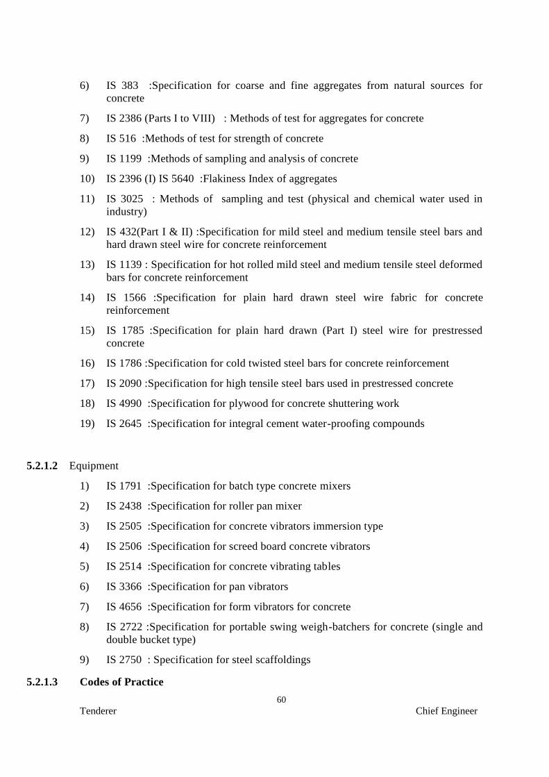
60
Tenderer Chief Engineer
6) IS 383 :Specification for coarse and fine aggregates from natural sources for
concrete
7) IS 2386 (Parts I to VIII) : Methods of test for aggregates for concrete
8) IS 516 :Methods of test for strength of concrete
9) IS 1199 :Methods of sampling and analysis of concrete
10) IS 2396 (I) IS 5640 :Flakiness Index of aggregates
11) IS 3025 : Methods of sampling and test (physical and chemical water used in
industry)
12) IS 432(Part I & II) :Specification for mild steel and medium tensile steel bars and
hard drawn steel wire for concrete reinforcement
13) IS 1139 : Specification for hot rolled mild steel and medium tensile steel deformed
bars for concrete reinforcement
14) IS 1566 :Specification for plain hard drawn steel wire fabric for concrete
reinforcement
15) IS 1785 :Specification for plain hard drawn (Part I) steel wire for prestressed
concrete
16) IS 1786 :Specification for cold twisted steel bars for concrete reinforcement
17) IS 2090 :Specification for high tensile steel bars used in prestressed concrete
18) IS 4990 :Specification for plywood for concrete shuttering work
19) IS 2645 :Specification for integral cement water-proofing compounds
5.2.1.2 Equipment
1) IS 1791 :Specification for batch type concrete mixers
2) IS 2438 :Specification for roller pan mixer
3) IS 2505 :Specification for concrete vibrators immersion type
4) IS 2506 :Specification for screed board concrete vibrators
5) IS 2514 :Specification for concrete vibrating tables
6) IS 3366 :Specification for pan vibrators
7) IS 4656 :Specification for form vibrators for concrete
8) IS 2722 :Specification for portable swing weigh-batchers for concrete (single and
double bucket type)
9) IS 2750 : Specification for steel scaffoldings
5.2.1.3 Codes of Practice

61
Tenderer Chief Engineer
1) IS 456 : Code of practice for plain and reinforced concrete
2) IS 1343 :Code of practice for prestressed concrete
3) IS 457 :Code of practice for general construction of plain and reinforced concrete
for dams and other massive structures
4) IS 3370 (Part I to IV) :Code of practice for concrete structures for storage of
liquids.
5) IS 3935 : Code of practice for composite construction
6) IS 3201 : Criteria for design and construction of precast concrete trusses
7) IS 2204 : Code of practice for construction of reinforced concrete shell roof
8) IS 2210 : Criteria for the design of RC shell structures and folded plates
9) IS 2751 : Code of practice for welding of mild steel bars used for reinforced
concrete construction
10 IS 2502: Code of practice for bending and fixing of bars for concrete
reinforcement
11) IS 3558 :Code of practice for use of immersion vibrators for consolidating
concrete
12) IS 3414 :Code of practice for design and installation of joints in buildings
13) IS 4014 (Part I&II) :Code of practice for steel tubular, scaffolding
14) IS 2571 :Code of practice for laying insitu - cement concrete flooring
5.2.1.4 Construction Safety
1) IS 3696 : Safety code for scaffolds and ladders
5.2.1.5 Measurement
1) IS 1200 :Method of measurement of building works
IS 3385 :Code of practice for measurement of civil engineering works
5.2.2 General
The quality of materials, method and control of manufacture and transportation of
all concrete work irrespective of mix, whether reinforced or otherwise shall conform to the
applicable portions of this specification.
5.2.3 Materials
The ingredients to be used in the manufacture of standard concrete shall consist
solely of standard type portland cement, clean sand, natural coarse aggregate, clean water
and admixtures.
5.2.3.1 Cement

62
Tenderer Chief Engineer
5.2.3.1.1 If the Contractor is instructed to supply cement, then the following points
shall be applicable:
a. The cement to be used shall be ordinary Portland/Portland Pozolana cement
conforming to IS: 8112-1989 & IS:1489 part I respectively for 43 Grade OPC/PPC
unless otherwise mentioned. The cement procured should be of reputed brands such
as Malabar Cements, ACC, L&T, Shankar Cement, etc. and as approved by the
Engineer-in-Charge. As far as possible, all the cement shall be obtained from a
single source throughout the contract. Cement of different types shall not be mixed
together. Different brands of cements or same brand of cement from different
sources shall not be used without prior approval of the Engineer-in-Charge.
The cement shall be delivered at site in original sealed bags which shall be
labelled with the weight, date of manufacture, brand and type. Cement received in
torn or hand-stitched bags shall not be used. For volumetric batching of, concrete,
cement should be mixed only by box measurement. All cement should be fresh
when delivered and shall be stored in an approved manner in stores built by the
Contractor at his own cost. Set cement shall not be allowed to be used for any work.
b. A certified report attesting to the conformance of the cement to IS specifications
by the cement manufacturer’s chemist shall be furnished to engineer if demanded.
c. Cement held in storage for a period of sixty (60) days or longer shall be tested.
Should at any time Engineer have reasons to consider that any cement is defective,
then irrespective of its origin, and/or manufacturers test certificate, such cement
shall be tested immediately at contractor’s cost at an approved laboratory and until
the results of such tests are found satisfactory, it shall not be used in any work.
Contractor shall not be entitled to any claim of any nature on this account.
d. Contractor will have to make his own arrangements for storage of adequate quantity
of cement.
e. The site engineer shall be regularly notified when supplies of cement are made to the
site store. Copies of invoices shall be made available to the site engineer and a
common cement register shall be kept at his office showing the supply stock and
issue on a daily basis.
5.2.3.1.2 If the cement is supplied by the Client
a) Contractor will have to make his own arrangements for the storage of cement. If
supplies are arranged by owner, cement will be issued in quantities to cover work
requirements of one month or more, as deemed fit by Engineer and it will be the
responsibility of contractor to ensure adequate and proper storage. The storage
arrangements shall be such that there is no dead storage. The storage arrangement
shall be approved by Engineer.
5.2.3.2 Aggregates
5.2.3.2.1 Aggregate in general designates both fine and coarse inert materials used in
the manufacture of concrete. Fine aggregate is aggregate all of which passes through 4.75
mm IS sieve. Coarse aggregate is aggregate most of which is retained on 4.75 mm sieve.
Specification mentioned against various item of work may also be followed.
5.2.3.2.2 All fine and coarse aggregates proposed for use in the work shall be subject
to Engineer’s approval and after specific materials have been accepted the source of
supply of such materials should not be changed without prior approval of Engineer.

63
Tenderer Chief Engineer
5.2.3.2.3 Aggregates shall, except as noted above, consist of natural sands, crushed
stone and gravel from a source known to produce satisfactory aggregate for concrete and
shall be chemically inert, strong, hard, durable against weathering, of limited porosity and
free from deleterious materials that may cause corrosion of the reinforcement or may
impair the strength and/or durability of concrete. The grading of aggregates shall be such
as to produce a dense concrete of specified strength and consistency that will work readily
into position without segregation and shall be based on the mix design and preliminary
tests on concrete specified later.
5.2.3.2.4 Sampling and testing
Samples of the aggregates for mix design and determination of suitability shall be
taken under the supervision of Engineer and delivered to the laboratory, well in advance of
the scheduled placing of concrete. Records of tests which have been made on proposed
aggregates and on concrete made from this source of aggregates shall be furnished to
Engineer in advance of the work for use in determining aggregate suitability. The costs of
all such tests, sampling, etc., shall be borne by contractor.
5.2.3.2.5 Storage of Aggregates
All coarse and fine aggregates shall be stacked in stock separately in stock piles in
the materials yard near the work site or if instructed in bins properly constructed to avoid
inter mixing of different aggregates. Contamination with foreign materials and with earth
during storage and while heaping the materials shall be avoided. The aggregate must be of
specified quality not only at the time of receiving at site but more so at the time of loading
into mixer.
5.2.3.2.6 Screening and Washing
a) Sand shall be prepared for use for such screening or washing, or both, as
necessary, to remove all objectionable foreign matter while separating the sand
grains to the required size fractions.
b) Natural gravel and crushed rock shall be screened and/or washed for the removal
of dirt or dust coating, if so demanded by Engineer
5.2.3.3 Water
5.2.3.3.1 Water used for both mixing and curing shall be free from injurious amounts
of deleterious materials. Potable waters are generally satisfactory for mixing and curing
concrete.
5.2.3.3.2 In case of doubt, the suitability of water for making concrete shall be
ascertained by the compressive strength and initial setting time test specified in IS-456.
The sample of water taken for testing shall be typical of the water proposed to be used for
concreting, due account being paid to seasonal variation. The sample shall not receive any
treatment before testing other than that envisaged in the regular supply of water proposed
for use in concrete. The sample shall be stored in a clean container previously rinsed out
with similar water.
5.2.3.4 Brick aggregates
The brickbats shall be of new bricks well burnt, hard, durable and broken to sizes,
well graded. It shall be free from dust, the size shall be of 37 mm and down. It shall be
free from earth and other impurities.
5.2.4 Mix Design

64
Tenderer Chief Engineer
5.2.4.1 Classification
5.2.4.1.1 In case of concrete works, mix design may be necessary as per IS:456 for
certain items as directed by Engineer-in-charge. All concrete in the works shall be
of design mix as defined in IS 456, unless it is a nominal mix concrete such as
1:3:6, 1:4:8, 1:5:10. Whether reinforced or otherwise, all design mix concrete
works to be carried out under this specification shall be divided into the following
classifications. (Also refer Clause 5.2.6.3 for testing of concrete)
MINIMUM COMPRESSIVE STRENGTH OF 15 CM CUBES AT
7 AND 28 DAYS AFTER MIXING, CONDUCTED IN ACCORDANCE WITH IS 516
5.2.4.1.2 It shall be very clearly understood that whenever the class of concrete such
as M 20 is specified it shall be the Contractor’s responsibility to ensure that minimum
crushing strength stipulated for the respective class of concrete is obtained at works. The
maximum total quantity of aggregate by weight per 50 kg of cement shall not exceed 250
kg except when otherwise specifically permitted by Engineer.
5.2.4.1.3 To fix the grading of aggregates, water cement ratio, workability and the
quantity of cement required to give preliminary and works cubes of the minimum strength
specified, the proportions of the mix shall be determined by weight. Adjustment of
aggregate proportions due to moisture present in the aggregate shall be made. Mix
proportioning shall be carried out according to Indian Standard Specifications.
5.2.4.1.4 Whenever there is a change either in required strength of concrete or water
cement ratio or workability or the source of aggregates and/or cement, preliminary
tests shall be repeated to determine the revised proportions, of the mix to suit the
altered conditions.
5.2.4.1.5 While fixing the value for water cement ratio for preliminary mixes,
assistance may be derived from the graph (appendix IS 456) showing the relationship
between the 28 day compressive strengths of concrete mixes with different water cement
ratios and the 7 days compressive strength of cement tested in accordance with IS 269.
5.2.4.2 Preliminary tests
5.2.4.2.1 Test specimens shall be prepared with at least two different water/cement
ratios for each class of concrete, consistent with workability required for the nature of the
work. The materials and proportions used in making preliminary tests shall be similar in
all respects to those to be actually employed in the works as the object of these tests is to
determine the proportions of cement, aggregates and water necessary to produce concrete
of required consistency and to give the specified strength. It will be the Contractor’s sole
responsibility to carry out these tests and he shall therefore furnish to Engineer a statement
of proportions proposed to be used for the various concrete mixes.
5.2.4.2.2 Materials shall be brought to the room temperature and all materials shall
be in a dry condition. The quantities of water, cement and aggregates for each mix shall
be determined by weight/volume to an accuracy of 1 part in 1000 parts.
Class Preliminary N/SQ.MM Work test N/SQ.MM Max. size of
aggregates
at 7 days at 28 days at 7 days at 28 days 40 or 20
M 30 28.0 42.0 20.0 33.0 40 or 20
M 25 23.5 35.0 17.0 28.0 40 or 20
M 20 19.4 29.0 13.5 22.0 40 or 20
M 15 14.0 17.0 10.0 16.0 40 or 20

65
Tenderer Chief Engineer
5.2.4.2.3 Mixing shall be done by a mixer machine as per IS 516 in such a manner as
to avoid loss of water. The cement and fine aggregate shall first be mixed dry until the
mixture is uniform in colour. The coarse aggregate shall then be added, mixed and water
added and mixed thoroughly for a period of not less than 3 minutes until the resulting
concrete is uniform in appearance. Each mix of concrete shall be of such a quantity as to
leave about 10% excess concrete after moulding the desired number of test specimens.
5.2.4.2.4 The consistency of each mix of concrete shall be measured immediately
after mixing, by the slump test in accordance with IS 1199. If in the slump test, care is
taken to ensure that no water or other materials is lost, the materials used for the slump test
may be remixed with the reminder of the concrete for making the specimen test cubes.
The period of remixing shall be as short as possible yet sufficient to produce a
homogeneous mass.
5.2.4.2.5 Compression tests of concrete cubes shall be made as per IS 516 on 15 cm
cubes. Each mould shall be provided with a metal base having a plane surface so as to
support the mould during filling without leakage. The base plate shall be preferably
attached to the mould by springs or screws. The parts of the mould when assembled shall
be positively and rigidly held together. Before placing concrete the mould and base plate
shall be cleaned and oiled. The dimensions and internal faces of the mould shall be
accurate within the following limits:
5.2.4.2.6 Height and distance between the opposite faces of the mould shall be of
specified size plus or minus 0.2 mm. The angle between the adjacent internal faces and
between internal faces and top and bottom planes of mould shall be 90 Deg. plus or minus
5 Deg. The interior faces of the mould shall be plane surfaces with a permissible variation
0.03 mm.
5.2.4.2.7 Concrete test cubes shall be moulded by placing fresh concrete in the
mould and compacted as specified in IS 516.
5.2.4.2.8 Curing shall be as specified in IS 516. The cubes shall be kept in moist air
of at least 90% relative humidity at a temp. of 27 Deg. Cent. plus or minus 2 Deg. Cent.
for 24 hours plus or minus half hour from the time of adding water to the dry ingredients.
Thereafter they shall be removed from the moulds and kept immersed in clean, fresh water
and kept at 27 Deg. Cent. plus or minus 2 Deg. Cent. temp. until required for test. Curing
water shall be renewed every seven days. A record of maximum and minimum
temperatures at the place of storage of the cubes shall be maintained during the period
they remain in storage.
5.2.4.2.9 Testing of specimens
The strength shall be determined based on not less than five cubes test specimens
for each age and each water cement ratio. All these laboratory test results shall be
tabulated and furnished to Engineer. The test result shall be accepted by Engineer if the
average compressive strengths of the specimens are tested subject to the condition that
only one out of the five consecutive test may give a value less than the specified strength
for that age. The Engineer may direct the Contractor to repeat the tests if the results are
not satisfactory and also to make such changes as he considers necessary to meet the
requirements specified. All these preliminary tests shall be conducted by the Contractor at
his own cost in an approved laboratory.
5.2.4.3 Proportioning, consistency, batching and mixing of concrete
5.2.4.3.1 Aggregate

66
Tenderer Chief Engineer
The proportions which shall be decided by conducting preliminary test shall be by
volume. These proportions of cement, fine and coarse aggregates shall be maintained
during subsequent concrete mixing. The supply of properly graded aggregate of uniform
quality shall be maintained over the period of work, the grading of aggregates shall be
controlled by obtaining the coarse aggregate in different sizes and blending them in the
right proportions. The different sizes shall be stocked in separate stock piles. The grading
of coarse and fine aggregate shall be checked as frequently as possible as determined by
Engineer, to ensure maintaining of grading in accordance with the samples used in
preliminary mix design. The material shall be stock piled well in advance of use.
5.2.4.3.2 Cement
The cement shall be measured by weight.
5.2.4.3.3 Water
Only such quantity of water shall be added to the cement and aggregates in the
concrete mix as to ensure dense concrete, specified surface finish, satisfactory workability,
consistent with the strength stipulated for each class of concrete. The water added to the
mix shall be such as not to cause segregation of material or the collection of excessive free
water on the surface of the concrete.
The water cement (W/C) ratio will be decided by Engineer-in-charge on weight
basis and this shall be strictly followed at site.
5.2.4.3.4 Proportioning by Water/Cement ratio
The W/C ratio specified for use by Engineer shall be maintained. The Contractor
shall determine the water content of the aggregates as frequently as directed by Engineer
as the work progress and as specified in IS 2386 (Part-III) and the amount of water
added at the mixer shall be adjusted as directed by Engineer so as to maintain the
specified W/C ratio. To allow for the variation in volume of aggregates due to variation in
their moisture content suitable adjustments in the volume of aggregates shall also be made.
5.2.4.3.5 Consistency and slump
Concrete shall be of a consistency and worability suitable for the conditions of the job.
After the amount of water required is determined, the consistency of the mix shall
be maintained throughout the progress of the corresponding parts of the work and
approved tests e.g. slump tests, compacting factor tests, in accordance with IS 1199
shall be conducted from time to time to ensure the maintenance of such
consistency.
5.2.5 Slumps for Various Types of Construction
Only sufficient quantity of water shall be added to concrete during the mixing to
produce a mix of sufficient workability to enable it to be well consolidated, to be worked
into the corners of the shuttering and around the reinforcement, to give the specified
surface finish, and to have the specified surface strength. The following slumps shall be
adopted for different kinds of works:
Placing Conditions Degree of
Workability
Slump
(mm)
[1] [2] [3]
Blinding concrete:
Shallow sections;
Pavements using pavers
Very low

67
Tenderer Chief Engineer
Mass concrete:
Lightly reinforced sections in slabs,
beams, walls, columns:
Floors;
Hand placed pavements;
Canal lining;
Strip footings
Heavily reinforced sections in slabs,
beams, walls, columns;
Slipform work; Pumped concrete
Trench fill;
In-situ pilling
Tremie concrete
Low
Medium
High
Very high
25-75
50-100
75-100
100-150
5.2.6 Sampling and testing concrete in the field
5.2.6.1 Facilities required for sampling materials and concrete in the field shall be
provided by the Contractor at no extra cost. The following equipment with operator shall
be made available at Engineer’s request (all must be in serviceable condition):
a) One concrete cube testing machine suitable for 15 cm cubes of 100 tonnes capacity
with proving calibration ring.
b) Twelve cast iron cube moulds of 15 cm size
c) One Lab. balance to weigh upto 5 kg with sensivity of 10 gm.
d) One set of sieves for coarse and fine aggregates
e) One set of slump cone complete with tamping rod
f) A set of measures from 5 litre to 0.1 litre
g) One electric oven with thermostat upto 120 Deg. Cent.
h) One flakiness gauge
i) One elongation index gauge
j) One sedimentation pipette
k) One Pyconometer
l) Two calibrated glass jar of 1 litre capacity
5.2.6.2 Arrangement can be made by the contractor to have the cubes tested in an
approved laboratory in lieu of a testing machine at site at his expense, with the prior
consent of the Engineer.
5.2.6.3 At least 6 test cubes of each class of concrete shall be made for every 15.0
cu.m. of concrete or part thereof. Such samples shall be drawn on each day for each type
of concrete. Of each set of 6 cubes, three shall be tested at 7 days age and three at 28 days
age. The laboratory test results shall be tabulated and furnished to Engineer. Engineer
will pass the concrete if average strength of the specimens tested is not less than the
strength specified, subject to the condition that only one out of three consecutive tests may
give a value less than the specified strength but this shall not be less than 90% of the

68
Tenderer Chief Engineer
specified strength. The cubes shall be tested on 7th and 28th day from the day of casting
of the cubes.
5.2.7 Admixtures
5.2.7.1 Admixtures may be used in concrete only with the approval of Engineer
based upon evidence that, with the passage of time, neither the compressive strength nor
its durability reduced. Calcium chloride shall not be used for accelerating setting of the
cement for any concrete containing reinforcement, or embedded steel parts. When
calcium chloride is permitted to be used, such as in mass concrete works, it shall be
dissolved in water and added to the mixing water in an amount not to exceed 1.5% of the
volume of the cement in concrete. When admixtures are used, the designed concrete mix
shall be corrected accordingly. Admixtures shall be used as per manufacturer’s
instructions and in the manner and with the control specified by Engineer-in-charge.
5.2.7.2 Air entraining agents
Where specified and approved by Engineer, neutralised vinyl resin or any other
approved air-entraining agent may be used to produce the specified amount of air in the
concrete mix and these agents shall conform to the requirements of ASTM standard 6260,
air entraining admixtures for concrete. The recommended total air content of the concrete
is 4% plus minus 1%. The method of measuring air content shall be as per IS 1199.
5.2.7.3 Water reducing admixtures
Where specified and approved by Engineer-in-charge water reducing
lignosulfonate mixture shall be added in quantities specified by Engineer. The
admixtures shall be added in the form of a solution.
5.2.7.4 Retarding admixtures
Where specified and approved by Engineer-in-charge retarding agents shall be
added to the concrete mix in quantities specified by Engineer.
5.2.7.5 Water proofing agent
Where specified and approved by Engineer-in-charge water proofing agent
conforming to IS 2645 shall be added in quantities specified by Engineer.
5.2.8 Optional tests
5.2.8.1 Engineer-in-charge may order tests to be carried out on cement, sand,
coarse aggregate and water in accordance with the relevant Indian Standards. Tests on
cement shall include (i) fineness test (ii) test for normal consistency (iii) test for setting
time (iv) test for soundness (v) test for tensile strength (vi) test for compressive strength
(vii) test for heat of hydration by experiment and by calculations in accordance with IS
269. Tests on sand shall include (i) sieve test (ii) test for organic impurities (iii)
decantation test for determining clay and silt content (iv) specific gravity test (v) test
for unit weight and bulkage factor. Tests on coarsed aggregate shall include (i) test for
sieve analysis (ii) specific gravity and unit weight of dry loose and rodded aggregate (iii)
soundness and alkali aggregate reactivity (iv) pertrographic examination (v) deleterious
materials and organic impurities (vi) test for aggregate crushing value. Any or all these
tests would normally be ordered to be carried out only if Engineer feels the materials are

69
Tenderer Chief Engineer
not in accordance with the specifications or if the specified concrete strengths are not
obtained and shall be performed by contractor at site or at an approved test laboratory.
5.2.8.2 If the work cubes do not give the stipulated strengths Engineer-in-charge reserves
the right to ask contractor to dismantle such portions of the work which in his opinion are
unacceptable and re-do the work to the standard stipulated at contractor’s cost.
5.2.9 Preparation prior to concrete placement
5.2.9.1 Before the concrete is actually placed in position, the insides of the form
work shall be inspected to see that they have been cleaned and oiled. Temporary openings
shall be provided to facilitate inspection, especially at bottom of columns and walls forms
to permit removal of saw dust, wood shavings, binding wire, rubbish dirt, etc. Openings
shall be placed or holes drilled so that these materials and water can be removed easily.
Such openings/holes shall be later suitably plugged.
5.2.9.2 The various agencies shall be permitted ample time to install drainage and
plumbing lines in floor and treech drains, conduits, hangers, anchors, inserts, sleeves,
bolts, frames and other miscellaneous embedments to be cast in the concrete as indicated
on the drawings or as is necessary for the proper execution of the work. Contractor shall
cooperate fully with all such agencies and shall permit the use of scaffolding form work,
etc., by other agencies at no extra cost.
5.2.9.3 All embedded parts, inserts, etc., supplied by Owner or Contractor shall be
correctly positioned and securely held in the forms to prevent displacement during
depositing and vibrating of concrete.
5.2.9.4 Anchor bolts shall be positioned and kept in place with the help of properly
manufactured templates. The use of all such templates, fixture, etc., shall be deemed to be
included in the rates.
5.2.9.5 Slots, openings, holes, pockets, etc., shall be provided in the concrete work in the
positions indicated in the drawings or as directed by Engineer-in-charge.
5.2.9.6 Prior to concrete placement all work shall be inspected and approved by Engineer
and if found unsatisfactory, concrete shall not be poured until after all defects have been
corrected at Contractor’s cost. Cat ladders shall be provided on the reinforcement to
facilitate labour movement.
5.2.9.7 Approval by Engineer for all materials and work as required herein shall not
relieve contractor from his obligation to produce finished concrete in accordance with the
drawings and specifications.
5.2.9.8 No concrete shall be placed in wet weather or on water covered surface. Any
concrete that has been washed by heavy rains, the work shall be entirely removed, if there
is any sign of cement and having been washed from the concrete mixture. To guard
against damage which may be caused by rains, the works shall be covered with tarpaulins
immediately after the concrete has been placed and compacted. Any water accumulating
on the surface of the newly placed concrete shall be removed by approved means and no
further concrete shall be placed thereon until such water is removed. To avoid flow of
water over/around freshly placed concrete, suitably drains and sumps shall be provided.
5.2.9.9 Immediately before concrete placement begins, proposed surfaces except
framework, which will come in contact with the concrete to be placed, shall be covered
with a bonding mortar.
5.2.10 Transportation

70
Tenderer Chief Engineer
5.2.10.1 All buckets, containers or conveyors used for transporting concrete shall be
mortar tight. Irrespective of the method of transportation adopted, concrete shall be
delivered with the required consistency and plasticity without segregation or loss of
slump. However, chutes shall not be used for transport of concrete without the written
permission of Engineer and concrete shall not be rehandled before placing.
5.2.10.2 Concrete must be placed in its final position before it becomes too stiff to
work. On no account, water shall be added after the initial mixing concrete which has
become stiff or has been contaminated with foreign materials shall be rejected and
disposed off as directed by Engineer.
5.2.10.3 All equipment used for mixing, transporting and placing of concrete shall
be maintained in clean condition. All pans, buckets, hoppers, chutes, pipelines and other
equipment shall be thoroughly cleaned after each period of placement.
5.2.11 Procedure for placing of concrete
5.2.11.1 Before any concrete is placed, the entire placing programme, consisting of
equipment, layout proposed procedures and methods shall be submitted to engineer for
approval if so demanded by Engineer and no concrete shall be placed until Engineer’s
approval has been received. Conveyor for conveying concrete shall be of such size and
design as to ensure a practically continuous flow of concrete during depositing without
segregation of materials, considering the size of the job and placement location.
5.2.11.2 Concrete shall be placed in its final position before the cement shall
normally be compacted in its final position within thirty minutes of leaving the mixer and
once compacted it shall not be disturbed.
5.2.11.3 Concrete, in all cases, be deposited as nearly as practicable directly in its
final position, and shall not be rehandled or caused to flow in a manner which will cause
segregation, loss of materials, displacement of reinforcement, shuttering or embedded
inserts or impair its strength. For locations where direct placement is not possible, and in
narrow forms, contractor shall provide suitable drop and elephant trunks to confine the
movement of concrete. Special care shall be taken when concrete is dropped from a
height especially if reinforcement is in the way, particularly in columns and thin walls.
5.2.11.4 Except when otherwise approved by Engineer, concrete shall be placed in
shovels or other approved implements and shall not be dropped from a height more than 1
M or handled in a manner which will cause segregation.
5.2.11.5 The following specification shall apply when placing of concrete by use of
mechanical equipment is specifically called for while inviting bids or is warranted
considering the nature of work involved. The control of placing shall begin at the mixer
discharger, concrete shall be discharged by a vertical drop into the middle of the bucket or
hopper and this principle of a vertical discharge of concrete shall be adhered to thoroughly
all stages of delivery until the concrete comes to rest in its final position.
5.2.11.6 Central bottom dump buckets of a type that provides for positive
regulation of the amount and rate of deposition of concrete in all dumping position, shall
be employed.
5.2.11.7 In placing concrete in large open areas, the bucket shall be spotted directly
over the position designated and then lowered for dumping. The open bucket shall clear
the concrete already in place and the height of drop shall not exceed 1 M. The bucket
shall be opened slowly to avoid high vertical bounce. Dumping of buckets on the swing or
in any manner which results in separation of ingredients or disturbance of previously
placed concrete will not be permitted.

71
Tenderer Chief Engineer
5.2.11.8 Concrete placed in restricted forms by wheel barrows, buggies, cars, short
chutes or hand shovelling shall be subject to the requirement for vertical delivery of
limited height to avoid segregation and shall be deposited as nearly as practicable in its
final position.
5.2.11.9 Where it is necessary to use transfer chutes, specific approval of Engineer
must be obtained to the type, length, slopes, baffles, vertical terminals and timing of
operations, the discharge and without segregation. To allow for the loss of mortar against
the sides of the chutes, the first mix shall have less coarse aggregate. During cleaning of
chutes the waste water shall be kept clear of the forms. Concrete shall not be permitted to
fall from the end of the chutes by more than 1 M. Chutes when approved for use shall
have slopes not flatter than 1:2 chutes shall be of metal or metal lined and of rounded cross
section. The slopes of all chutes sections shall be approximately the same. The discharge
end of the chutes shall be maintained above the surface of the concrete in the forms.
5.2.11.10 Concrete may be conveyed and placed by mechanically operated
equipment e.g. pumps or pneumatic placers only with the written permission of Engineer.
The slump shall be held to the minimum, necessary for conveying concrete by this
method.
5.2.11.11 When pumping is adopted, before pumping of concrete is started, the
pipeline shall be lubricated with one or two batches of mortar composed of one part
cement and two parts sand. The concrete mix shall be specially designed to suit pumping.
Care shall be taken to avoid stoppages in work once pumping has started.
5.2.11.12 When pneumatic placer is used, the manufacturer’s advice on layout of
pipeline shall be followed to avoid blockages and excessive wear. Restraint shall be
provided at the discharge box to cater for the reaction at this end. Manufacturer’s advice
shall be followed regarding concrete quality and all other related matters when pumping or
pneumatic placing equipment are used.
5.2.11.13 Concreting, once started, shall be continuous until the pour is completed.
Concrete shall be placed in successive horizontal layers of uniform thickness ranging from
15 to 90 mm as directed by Engineer. These shall be placed as rapidly practicable to
prevent the formation of cold joints or planes of weakness between each succeeding layer
within the pour. The thickness of each layer shall be such that it can be deposited before
the previous layer has stiffened. The bucket loads or other units of deposit shall be spotted
progressively along the face of the layer with such overlap as well facilitate spreading the
layer to uniform depth and texture with a minimum of shovelling. Any tendency to
segregation shall be corrected by shovelling stones into mortar rather than mortar on to
stones. Such a condition shall be corrected by redesign of mix or other means, as directed
by Engineer.
5.2.11.14 The top surface of each pour and bedding planes shall be approximately
horizontal unless otherwise instructed.
5.2.12 Compaction
5.2.12.1 Concrete shall be compacted during placing with approved vibrating
equipment until the concrete has been consolidated to the maximum practicable density, is
free of pockets of coarse aggregate and fits tightly against all form surfaces, reinforcement
and embedded fixtures. Particular care shall be taken to ensure that all concrete placed
against the forms faces and into corners of forms or against hardened concrete at joints is
free from voids or cavities. The use of vibrators shall be consistent with the concrete mix
and caution exercised not to over-vibrate the concrete to the point that segregation results.

72
Tenderer Chief Engineer
5.2.12.2 Vibrators shall conform to IS specifications. Type of vibrator to be used
shall depend on the structure where concrete is to be placed. Shutter vibrators to be
effective, shall be firmly secured to the formwork which must be sufficiently rigid to
transmit the vibration and strong enough not to be damaged by it. Immersion vibrators
shall have no load frequency, amplitude and acceleration as per IS 2505 depending on the
size of vibrator. Immersion vibrators in sufficient numbers and each of adequate size shall
be used to properly consolidate all concrete. Tapping or external vibrating of forms by
hand tools or immersion vibrators will not be permitted.
5.2.12.3 The exact manner of application and the most suitable machines for the
purpose must be carefully considered and operated by experienced men. Immersion
vibrators shall be inserted vertically at points not more than 450 mm apart and withdrawn
when air bubbles cease to come to the surface. Immersion vibrators shall be withdrawn
very slowly. In no case shall immersion vibrators be used to transport concrete inside the
forms. Particular attention shall be paid to vibration at the top of a lift e.g. in a column or
wall.
5.2.12.4 When placing concrete in layers, which are advancing horizontally as the
work progresses, great care shall be exercised to ensure adequate vibration, blending and
mixing of the concrete between the succeeding layers.
5.2.12.5 The immersion vibrator shall penetrate the layer being placed and also
penetrate the layer below with the underlayer is still plastic to ensure good bond and
homogeneity between the two layers and prevent the formation of cold joints.
5.2.12.6 Care shall be taken to prevent contact of immersion vibrators against
reinforcement steel. Immersion vibrators shall not be allowed to come in contact with
reinforcement steel after start of initial set. They shall also not be allowed to come in
contact with forms or finished surfaces.
5.2.12.7 Form attached vibrators shall be used only with specific authorisation of
Engineer.
5.2.12.8 The surface vibrators will not be permitted under normal conditions.
However for thin slabs vibration by specially designed vibrators may be permitted upon
approval of Engineer.
5.2.12.9 The formation of stone pockets or mortar bondages in corner and against
faces of forms shall not be permitted. Should these occur, they shall be dug out, reformed
and refilled to sufficient depth and shape for through bonding, as directed by Engineer.
5.2.13 Placement interval
Except when placing with slip forms each placement of concrete in multiple lift
work, shall be allowed to set for atleast 24 hours after the final set of concrete and before
the start of a subsequent placement.
5.2.14 Special provision in placing
When placing concrete in walls with openings and in floors of integral slab and
beam construction and other similar conditions, the placing shall stop when the concrete
reaches the top of the opening in walls and bottom horizontal surface of the slab, as the
case may be placing shall be resumed before the concrete in place takes initial set, but not
until it has time to settle as determined by Engineer.
5.2.15 Placing concrete through reinforcement steel
When placing concrete through reinforced steel, care shall be taken to prevent
segregation of the coarse aggregate. When the congestion of steel makes placing difficult

73
Tenderer Chief Engineer
it may be necessary to temporarily move the top steel aside to get proper placement and
restore reinforcing steel to design position.
5.2.16 Bleeding
Bleeding of free water, on top of concrete being deposited, in to the forms shall be
caused to stop the concrete pour. The conditions causing this defect corrected before any
further concreting is resumed.
5.2.17 Curing, protecting, repairing and finishing
5.2.17.1 Curing
5.2.17.1.1 All concrete shall be cured by keeping it continuously damp for the period
of time required for complete hydration and hardening to take place. Preference shall be
given to the use of continuous sprays or ponded water continuously saturated covering of
sacks, canvas, hessian, polythene sheets or other absorbent materials, or approved
effective curing compounds applied with spraying equipment capable of producing a
smooth, even textured coat. Extra precautions shall be exercised in curing concrete during
cold and hot water as outlined hereinafter. The quality of curing water shall be the same
as that used for mixing concrete.
5.2.17.1.2 Certain types of finish or preparation for overlaying concrete must be done
at certain stage of the curing process and special treatment may be required for specific
concrete surface finish.
5.2.17.1.3 Curing of concrete made of high alumina cement and supersulphated
cement shall be carried out as directed by Engineer.
5.2.17.1.4 Fresh concrete shall be kept continuously wet for a minimum period of 15
days from the date of placing of concrete following a lapse of 12 to 14 hours after laying
of concrete. The curing of horizontal surfaces exposed to the drying winds shall however
begin immediately the concrete has hardened. Water shall be applied uniformly to
concrete surfaces within 1 hour after concrete has set. Water shall be applied to formed
surfaces immediately upon removal of forms. Quantity of water applied shall be
controlled so as to prevent erosion of freshly placed concrete.
5.2.17.1.5 Curing shall be assured by use of an ample water supply under pressure in
pipes with all necessary appliance of hose, sprinklers and spraying devices. Continuous
fine mist spraying or sprinkling shall be used, unless otherwise specified or approved by
Engineer.
5.2.17.1.6 Whenever, by the judgement of Engineer, it may be necessary to omit the
continuous spray method, a covering of clean sand or other approved means such as wet
gunny bags which will prevent loss of moisture from the concrete, may be used. No type
of covering will be approved which would stain or damage the concrete during or after the
curing period. Covering shall be kept continuously wet during the curing period.
5.2.17.1.7 For curing of concrete in pavements, side-walks floors, flat roofs or other
level surfaces, the ponding method of curing is preferred. The method of containing the
ponded water shall be approved by Engineer. Special attention shall be given to edges and
corners of the slabs to ensure proper protection to these area. The ponded area shall be
kept continuously filled with water during the curing period.
5.2.17.1.8 Surface coating type compounds shall be used only by special permission
of Engineer, curing compounds shall be liquid type white pigmented. Other curing

74
Tenderer Chief Engineer
compounds shall be used on surfaces where future blending with concrete, water or acid
proof membrane or painting is specified.
5.2.17.1.9 All equipment and materials required for curing shall be on hand and ready
for use before concrete is placed.
5.2.17.2 Protecting fresh concrete
5.2.17.2.1 Fresh concrete shall be protected from defacements and damage due to
construction operation by leaving forms in place for an ample period as specified later in
this specifications. Newly placed concrete shall be protected by approved means such as
tarpaulins from rain, sun and winds. Steps as approved by Engineer shall also be taken to
protect immature concrete from damage by debris, excessive loading, vibration, abrasion
or contact with other materials, etc., that may impair the strength and/or durability of the
concrete. Workmen shall be warned against and prevented from disturbing green concrete
during its setting period. If it is necessary that workmen enter the area of freshly placed
concrete, Engineer may require that bridges be placed over the area.
5.2.17.3 Repair and replacement of unsatisfactory concrete
5.2.17.3.1 Immediately after the shuttering is removed, the surface of concrete shall
be very carefully inspected and all defective areas called to the attention of Engineer who
may permit patching of the defective areas or also reject the concrete unit either partially
or entirely. Rejected concrete shall be removed and replaced by contractor at no
additional expense to owner. Holes left by form bolts, etc., shall be filled up and made
good with mortar composed of one part of cement to one and half parts of sand passing
2.36 mm IS sieve after removing any loose stones adhering to the concrete shall be
finished as described under the particular items of work.
5.2.17.3.2 Superficial honeycombed surfaces and rough patches shall be similarly
made good immediately after removal of shuttering in the presence of Engineer and
superficial water and air holes shall be filled in. The mortar shall be well worked into the
surface with a wooden float. Excess water shall be avoided. Unless instructed otherwise
by Engineer the surface of the exposed concrete placed against shuttering shall be rubbed
down immediately on removal of shuttering to remove fine or other irregularities and
necessary care being taken to avoid damage to the surface. Surface irregularities shall be
removed by grinding.
5.2.17.3.3 If reinforcement is exposed or the honey combing occurs at vulnerable
positions eg. ends of beams or columns it may be necessary to cut out the member
completely or in part and reconstruct. The decision of Engineer shall be final in this
regard. If only patching is necessary, the defective concrete shall be cut out till solid
concrete is reached (or to a minimum depth of 25 mm) the edges being cut perpendicular
to the affected surface or with small under cut if possible. Achors, tees or dovetail slots
shall be provided whenever necessary to attach the new concrete securely in place an area
extending several centimetres beyond the edges and the surfaces of the prepared voids
shall be saturated with water for 24 hours immediately before the patching material is
placed.
5.2.17.3.4 The use of epoxy for bonding fresh concrete used for repairs will be
permitted upon written approval of Engineer. Epoxy shall be applied in strict accordance
with the instructions of the manufacturer.
5.2.17.3.5 Small size holes having surface dimensions about equal to the depth of the
hole, holes left after removal of form bottom, grout insert holes and slots cut for repair of

75
Tenderer Chief Engineer
cracks shall be repaired as follows. The hole to be patched shall be roughened and
thoroughly soaked with clean water until absorption stops.
5.2.17.3.6 A 5 mm thick layer of grout of equal parts of cement and sand shall be well
brushed into the surface to be patched, followed immediately by the patching concrete
which shall be well consolidated with a wooden float. The concrete patch shall be built up
in 10 mm thick layers. After an hour or more, depending upon weather conditions, it shall
be worked off flush with a wooden float and smooth finish obtained by wiping with
hessian, a steel trowel shall be used for this purpose. The mix for patching shall be of
same materials and in the same proportions as that used in the concrete being repaired,
although some reduction in the maximum size of the coarse aggregates may be necessary
and the mix shall be kept as dry as possible.
5.2.17.3.7 Mortar filling by air pressure (guniting) shall be used for repairing of areas
too large and/or too shallow for patching with mortar. Patched surfaces shall be given a
final treatment to match the colour and texture of the surrounding concrete. While cement
shall be substituted for ordinary cement, if so directed by Engineer, to match the shade of
the patch with original concrete.
5.2.17.3.8 The patched area shall be covered immediately with an approved non-
staining water saturated material such as gunny bag which shall be kept continuously wet
and protected against sun and wind for a period of 24 hours. Thereafter, the patched area
shall be kept wet continuously by fine spray of sprinkling for not less than 10 days.
5.2.17.3.9 All materials, procedures and preparation used in the repairing of concrete
and also the finished repair work shall be subject to the approval of Engineer. All fillings
shall be tightly bonded to the concrete and shall be sound, free from shrinkage cracks after
the fillings have been cured and finished.
5.2.17.4 Finishing
5.2.17.4.1 The type of finish for formed concrete surface shall be as follows, unless,
otherwise specified by the Engineer.
5.2.17.4.2 For surfaces against which backfill or concrete is to be placed, no treatment
is required except repairing of defective area.
5.2.17.4.3 For surface below grade which will receive waterproofing treatment the
concrete shall be free of surface irregularities which would interfere with proper
application of the waterproofing material which is specified for use.
5.2.17.4.4 Unless specified, surfaces which will be exposed when the structure is in
service shall receive no special finish, except repairing of damage or defective concrete
removal of fins and abrupt irregularities, fillings of holes let by form ties and rods and
clean up of loose or adhering debris.
5.2.17.4.5 Surfaces which will be exposed to the weather and which would normally
be level, shall be sloped for drainage. Unless the drawing specifies such as stair treads,
walls shall be sloped across the width approximately 1 in 30 broader surface such as
walkways, roads, parking areas and platforms shall be sloped about 1 in 50. Surfaces that
will be covered by backfill or concrete subfloors to be covered either concrete topping,
terrazzo or quarry tile and similar surfaces shall be smooth screeded and levelled to
produce even surfaces. Surface irregularities shall not exceed 6 mm. Surfaces which will
not be covered by backfill, concrete or tile toppings such as outside decks, floors of
galleries and sumps, parapets, gutters, sidewall floors and slabs shall be consolidated,
screeded and floated. Excess water and laitance shall be removed before finishing.
Floating may be done with hand or power tools and started as the screeded surface has

76
Tenderer Chief Engineer
attained a stiffness to permit finishing operation and these shall be the minimum required
to produce a surface uniform in texture and free from screed marks or other imperfections.
Joints edges panels and forms linings shall be of uniform size and be as large as
practicable and installed with closed joints. Upon removal of forms the joint marks shall
be smoothed off and all blemishes, projections etc., removed leaving the surfaces
reasonably smooth and unmarked.
5.2.17.4.6 Integral cement concrete finish
When specified on the drawings and integral cement concrete finish of specified
thickness for floors and slabs shall be applied either monolithic or bonded as specified on
the drawing as per IS 2571. The surface shall be compacted and then floated with a
wood float or power floating machine. The surface shall be tested with a straight edge and
any high and low spots eliminated. Floating or trowelling of finish shall be permitted
only after all surface water has evaporated. Dry cement or a mixture of dry cement and
sand shall not be sprinkled directly on the surface of the cement finish to absorb moisture
or to stiffen the mix.
5.2.17.4.7 Exposed Concrete finish/Rendering
A rubbed finish shall be provided only on exposed concrete surfaces as specified
on the drawings. Upon removal of forms, all fins and other projections on the surfaces
shall be carefully removed, off-sets levelled and voids and damaged sections be
immediately saturated with water and repaired by filling with a concrete or mortar of the
same composition as was used in the surface. Then surface shall be thoroughly wetted and
rubbed with carborundum or other abrassive. Cement mortar may be used in the rubbing,
but the finished surface shall be brush coated with either cement grout after rubbing. The
finished surfaces shall present a uniform and smooth appearance.
5.2.18 Form Work
5.2.18.1 The formwork shall consist of shores, bracings, sides of beams and
columns, bottom of slabs, etc., including ties anchors, hangers inserts, etc., complete
which shall be properly designed and planned for the work. False work shall be so
constructed that necessary adjustment can be made to compensate for take up and
settlements. Wedge may be used at the top or bottom of timber shores but not at both ends
to facilitate vertical adjustment or dismandling of the formwork.
5.2.18.2 Design of formwork
The design of the formwork as well as its construction shall be the responsibility of
Contractor. If so instructed, the drawings and/or calculation for the design for the
formwork shall be submitted to Engineer for approval before proceeding with work, at no
extra cost. Engineer’s approval shall not however relieve Contractor of the full
responsibility for the design and construction of the formwork. The design shall take into
account all the load vertical and lateral that the forms will be carrying live and vibration
loadings.
5.2.18.3 Type of formwork
Formwork may be of timber, plywood, metal, plastic or concrete. For special
finishes the formwork may be lined with plywood, steel, sheets, oil, tempered hard board,
etc. Sliding forms and slip forms may be used with the approval of Engineer.
5.2.18.4 Form work requirements

77
Tenderer Chief Engineer
5.2.18.4.1 Forms shall conform to the shapes, lines, grades and dimensions including
camber of the concrete as called for on the drawings. Ample studs, braces, ties, straps,
etc., shall be used to hold the forms in proper position without any distortion whatsoever
until the concrete is set sufficiently to permit removal of forms. Forms shall be strong
enough to permit the use of immersion vibrators. In special cases form vibrators may also
be used. The shuttering shall be close boarded. Timber shall be well seasoned, free from
sap, shakes, loose knots, worm holes, warps or other surface defects in contact with
concrete. Faces coming in contact with the concrete shall be free from adhering grout,
plaster, paint, projecting nails, splits or other defects. Joints shall be sufficiently tight
splits or other defects. Joints shall be sufficiently tight to prevent loss of water or any fine
material from concrete.
5.2.18.4.2 Plywood shall be used for exposed concrete surfaces; where called for.
Sawn and wrought timber may be used for unexposed surfaces. Inside faces of forms for
concrete surfaces which are to be rubbed finished shall be planed to remove irregularities
or unevenness in the face. Formwork with linings shall be permitted.
5.2.18.4.3 All new and used form timber shall be maintained in a good condition with
respect to shape, strength, rigidity, water tightness, smoothness and cleanliness of
surfaces. Form timber unsatisfactory in any respect shall not be used and if rejected by
Engineer shall be removed from the site.
5.2.18.4.4 Shores supporting successive members shall be placed directly over those
below or be so designed and placed that the load will be transmitted directly to them.
Trussed supports shall be provided for shores that cannot be secured on adequate
foundations.
5.2.18.4.5 Formwork, during any stage of construction showing signs of distortion or
distored to such a degree that the intended concrete work will not conform to the exact
contours indicated on the drawings, shall be repositioned and strengthened. Poured
concrete affected by the faulty formwork, shall be removed completely and the formwork
be corrected prior to placing of new concrete.
5.2.18.4.6 Excessive construction camber to compensate for shrinkage, settlement
may impair the structural strength of members and shall not be permitted.
5.2.18.4.7 Forms shall be so designed that their removal will not damage the concrete.
Face formwork shall provide true vertical and horizontal joints, conform to the
architectural features of the structure as to location of joints and be as directed by
engineer.
5.2.18.4.8 Where exposed smooth or rendered concrete finishes are required the forms
shall be constructed with special care so that the resulting concrete surfaces require a
minimum finish.
5.2.18.5 Formwork For Slope Surfaces
5.2.18.5.1 Forms for sloped surfaces shall be built so that the formwork can be placed
board-by-board immediately ahead of concrete placement so as to enable ready access for
placement, vibration inspection and repair of the concrete.
5.2.18.5.2 The formwork shall also be built so that the boards can be removed one by
one from the bottom up as soon as the concrete has attained sufficient stiffness to prevent
sagging. Surfaces of construction joints and finished surfaces with slopes steeper than 4
horizontal: 1 vertical shall be formed as required herein.
5.2.18.6 Formwork for Curved Surfaces

78
Tenderer Chief Engineer
5.2.18.6.1 The contractor shall interpolate intermediate sections as necessary and shall
construct the forms so that the curvature will be continuous between sections. Where
necessary to meet requirements for curvature, the form timber shall be built up of
laminated splines cut to make tight, smooth form surfaces.
5.2.18.6.2 After the forms have been constructed, all surface imperfections shall be
corrected and all surface irregularities at matching faces of form material shall be deressed
to the specified curvature.
5.2.18.7 Formwork for Exposed Concrete Surfaces
5.2.18.7.1 Where it is desired, directed or shown on the drawings to have original fair
face finish of concrete surface without any rendering or plastering, formwork shall be
carried out by using wood planks, plywood or steel plates of approved quality and as per
direction of the Engineer.
5.2.18.7.2 The contractor shall use one type of material for all such exposed concrete
faces and the forms shall be constructed so as to produce uniform and consistent texture
and pattern on the face of the concrete. Patches or forms for these surfaces will not be
permitted. The formwork shall be placed so that all horizontal formworks are continuous
across the entire surface.
5.2.18.7.3 To achieve a finish which shall be free of board marks, the formwork shall
be faced with plywood or equivalent material in large sheets. The sheets shall be arranged
in an approved pattern. Wherever possible, joints between sheets shall be arranged to
coincide with architectural features, chills, window heads or change in direction of the
surface. All joints between shuttering plates or panels shall be vertical or horizontal unless
otherwise directed. Suitable joints shall be provided between sheets. The joints shall be
arranged and fitted so that no blemish or mark is imparted to the finished surfaces.
5.2.18.7.4 To achieve a finish which shall give the rough appearance of concrete cast
against sawn boards, formwork boards unless otherwise stated shall be of 150 mm wide,
securely jointed with tonge and grooved joints if required to prevent grout loss with tie rod
positions and direction of boards carefully controlled. Sawn boards shall be set
horizontally, vertically or at an inclination shown in the drawings. All bolt holes shall be
accurately aligned horizontally and vertically and shall be filled with matching mortar
recessed 5 mm back from the surrounding concrete face.
5.2.18.7.5 Forms for exposed concrete surfaces shall be constructed with grade strips
(the underside of which indicated top of pour) at horizontal construction joints, unless the
use of groove strips is specified on the drawings. Such forms shall be removed and reset
from lift to lift, they shall not be continuous from lift to lift. Sheeting of reset forms shall
be tightened against the concrete so that the forms will not be spread and permit abrupting
irregularities or loss of mortar. Supplementary form ties shall be used as necessary to hold
the reset forms tight against the concrete.
5.2.18.7.6 For fair faced concrete, the position of through bolts will be restricted and
generally indicated on the drawings.
5.2.18.7.7 Chamfer strips shall be placed in the corners of forms for exposed exterior
corners so as to produce 20 mm bevelled edges except where otherwise shown in the
drawings. Interior corners and edges at formed joints shall not be bevelled unless shown
on the drgs. Mouldings for grooves, drip courses and bands shall be made in the form
itself.
5.2.18.7.8 The wood planks, plywood and steel plates used in formwork for obtaining
exposed surfaces shall not be used for more than 3 times in case of wood planks, 6 times

79
Tenderer Chief Engineer
for plywood and 10 times for steel plates respectively. However, no forms will be allowed
for reuse, if in the opinion of the Engineer it is doubtful to produce desired texture of
exposed concrete.
5.2.18.7.9 In order to obtain exposed concrete work of uniform colour it shall be
necessary to ensure that the sand used for all exposed concrete work shall be of approved
uniform colour. Moreover the cement used in the concrete for any complete element shall
be from single consignment.
5.2.18.7.10 No exposed concrete surface shall be rendered or painted with cement or
otherwise. Plastering of defective concrete as a means of achieving the required finish
shall not be permitted, except in the case of minor porosity on the surface, the Engineer
may allow a surface treatment by rubbing down with cement and sand mortar of the same
richness and colour as for the concrete. This treatment shall be made immediately after
removing the formwork.
5.2.18.7.11 The contractor shall also take all precautionary measures to prevent
breaking and chipping of corners and edges of completed work until the building is
handed over.
5.2.18.8 Bracings struts and props
5.2.18.8.1 Shuttering shall be braced, strutted, propped and so supported that it shall
not deform under weight and pressure of the concrete and also due to the movement of
men and other materials. Bamboos shall not be used as props or cross bearers.
5.2.18.8.2 The shuttering for beams and slabs shall be so erected that the shuttering on
the sides of the beams and under the soffit of slabs can be removed without disturbing the
beam bottoms. Repropping of beams shall not be done except when props have to be
reinstated to take care of construction loads anticipated to be in excess of the design load.
Vertical props shall be supported on wedges or other measures shall be taken whereby the
props can be generally lowered vertically while striking the shuttering. If the shuttering
for a column, is erected for the full height of the column, one side shall be left open and
built up in sections as placing of concrete from the sides to limit the drop of concrete to 3
M or as directed by Engineer.
5.2.18.9 Mould Oil
Care shall be taken to see that the faces of form work coming in contact with
concrete are perfectly cleaned and two coats of mould oil or any other approved material
applied before fixing reinforcement and placing concrete. Such coating shall be insoluble
in water, non-staining and not injurious to the concrete. It shall not become flaky or be
removed by rain or wash water. Reinforcement and/or other items to be cast in the
concrete shall not be placed until coating of the forms is complete, adjoining concrete
surface shall also be protected against contamination from the coating material.
5.2.18.10 Chamfers and fillets
All corners and angles exposed in the finished structure shall be formed with
moulding to form chamfers or fillets on the finished concrete. The standard dimension of
chamfers and fillers, unless otherwise specified shall be 20 mm x 20 mm. Care shall be
exercised to ensure accurate mouldings. The diagonal face of the mouldings shall be
planned or surfaced to the same texture as the forms to which it is attached.
5.2.18.11 Wall ties

80
Tenderer Chief Engineer
Wire ties passing through the walls shall not be allowed. In their place bolts
through sleeves be used.
5.2.18.12 Reuse of forms
Before reuse, all forms shall be thoroughly scraped, cleaned, nails removed, holes
that may leak suitably plugged and joints examined and when necessary, repaired and the
inside retreated to prevent adhesion, to the satisfaction of Engineer. Warped timber shall
be resized. Contractor shall equip himself with enough shuttering material to complete the
job in the stipulated time.
5.2.18.13 Removal of forms
5.2.18.13.1 Contractor shall record on the drawings and in a special register the date
upon which the concrete is placed in each part of the work and the date on which the
shuttering is removed therefrom. The Contractor shall remove the shuttering after
obtaining the approval of the Engineer.
5.2.18.13.2 In no circumstances shall forms be struck until the concrete reaches a
strength of at least twice the stress due to self weight and any construction/erection
loading to which the concrete may be subjected at the time of striking formwork.
5.2.18.13.3 In normal circumstances (generally where temperatures are above 20 Deg.
Cent.) forms may be removed after expiry of the following periods:
Ordinary portland
cement concrete
Rapid hardening
portland cement
a) Walls columns and vertical
sides of beams
24 to 48 hrs as directed
by the Engineer
24 hrs.
b) Slabs proos left under 3 days 2 days
c) Beam soffits prods left under 7 days 4 days
d) Removal of props to slabs:
i) Spanning upto 4.5m
ii) Spanning over 4.5m.
7 days
14 days
4 days
8 days
e) Removal of props to beams &
arches
i) Spanning upto 6m
ii) Spanning over 6m
14 days
21 days
8 days
12 days
5.2.18.13.4 Striking shall be done slowly with utmost care to avoid damage to arises
and projections and without shock or vibration, by gently easing the wedges. If after
removing the form work, it is found that timber has been embedded in the concrete, it shall
be removed and made good as specified earlier.
5.2.18.13.5 Reinforced temporary openings shall be provided as directed by Engineer
to facilitate removal of formwork which otherwise may be inaccessible.
5.2.18.13.6 Tie rods, clamps, form bolts etc., which must be entirely removed from
walls or similar structures shall be loosened not sooner than 24 hours nor later than 40
hrs. after the concrete has been deposited. Ties, except those required to hold forms in
place, may be removed at the same time, Ties, withdrawn from walls and grade beams

81
Tenderer Chief Engineer
shall be pulled towards the inside face cutting ties back from the faces of walls and grade
beams will not be permitted.
5.2.18.13.7 For liquid retaining structures no sleeves for through bolts shall be used nor
shall through bolts be removed as indicated above. The bolts, in this case, shall be cut at
25mm depth from the surface and then the hole shall be made good by sand, cement
mortar of the same proportions as the concrete just after striking the formwork.
5.2.19 Reinforcement Steel
5.2.19.1 General
5.2.19.1.1 Reinforcement bars, if supplies are arranged by contractor unless otherwise
specified, shall be either plain round mild steel bars grade I as per IS 432 (Part I) or
medium tensile steel bar as per IS 432 (Part I) or hot rolled mild steel and medium tensile
steel deformed bars as per IS 1139 or cold twisted steel bars as per IS 1786, as shown and
specified on the drawings. Wire mesh or fabric shall be in accordance with IS 1566.
Substitution of reinforcement will not be permitted except upon written approval from
Engineer.
5.2.19.1.2 Plain round mild steel bars grade II as per IS 432 (Part I) may be used with
prior approval of Engineer in writing and with 10% increase in the reinforcement area but
its use shall not be permitted in structures located in earthquake zones subjected to severe
damage (as per IS 1895) and for structures subject to dynamic loading (other than wind
loading), such as frames supporting rotary or reciprocating machinery, etc.
5.2.19.1.3 All reinforcement shall be clean, free from grease, oil, paint, loose mill
scale, loose rust, dust, bituminous material or any other substances that will destroy or
reduce the bond. All rods shall be thoroughly cleaned before being fabricated. Pitted and
defective rods shall not be used.
5.2.19.1.4 All concrete in the works shall be of design mix as defined in IS 456,
unless it is a nominal mix concrete such as 1:3:6, 1:4:8 or 1:5:10. Whether reinforced or
otherwise, all design mix concrete works to be carried out under this specification shall be
divided into the following classifications:
5.2.19.2 Providing, fabricating and placing in position reinforcement steel 5.2.19.2.1 The quality of the steel shall be as mentioned in the materials section. The
bars shall be fabricated as per the drawings. Laps and splices for reinforcement shall be as
shown on the drawings. Splices in adjacent bars shall be approved by Engineer. The bars
shall not be lapped unless the length required exceeds the maximum available lengths of
bars at site.
5.2.19.3 Bending
5.2.19.3.1 Reinforcing bars supplied bent or in coils, shall be straightened before they
are cut to size. Straightening of bars shall be done in cold and without damaging the bars.
This is considered as a part of reinforcement binding fabricating work.
5.2.19.3.2 All bars shall be accurately bent according to the sizes and shapes shown
on the detailed working drawings/bar bending schedules. They shall be bent gradually by
machine or other approved means. Reinforcing bars shall not be straightened and rebent
in a manner that will injure the material, bars containing cracks or splits shall be rejected.
They shall be bent cold, except bars of over 32 mm in diameter which may be bent hot if
specifically approved by Engineer. Bars bent hot shall not be heated beyond cherry red
colour (not exceeding 845oC) and after bending shall be allowed to cool slowly without

82
Tenderer Chief Engineer
quenching. Bars incorrectly bent shall be used only if the means used for straightening
and rebending shall not injure the material. No reinforcement shall be bent when in
position in the work without approval whether or not it is partially embedded in hardened
concrete. Bars having kind orbends other than those required by design shall not be used.
5.2.19.4 Fixing
Reinforcement shall be accurately fixed by any approved means and maintained in
the correct position shown in the drawings by the use of block, spacers and chairs as per IS
2502 to prevent displacement during placing and compaction of concrete. Bars intended
to be in contact at crossing points shall be strongly bound together at all such points with
two no. 16 gauge anhealed soft iron wire. The vertical distance required between
successive layers of bar in beams or other members shall be maintained by providing of
mild steel spacer bars at such intervals that the main bars do not perceptibly sag between
adjacent spacer bars.
5.2.19.5 Cover
5.2.19.5.1 Unless indicated otherwise on the drawings, clear concrete cover for
reinforcement (exclusive of plaster or other decorative finish) shall be as follows:
a) At each end of reinforcing bar, not less than 25 mm nor less than twice the
diameter of the bar whichever is less.
b) For a longitudinal reinforcing bar in a column, not less than 40 mm, nor less than
the diameter of the bar. In case of columns of minimum dimensions of 20 cm or
under, with reinforcing bars of 12 mm and less in diameter, a cover of 25 mm may
be used.
c) For longitudinal reinforcing bars in a beam 25 mm nor less than the diameter of
the bar.
d) For tensile, compressive, shear, or other reinforcement in a slab or wall not less
than 12 mm nor less than the diameter of such reinforcement.
e) For any other reinforcement not less than 12 mm nor less than the diameter of such
reinforcement.
f) For footings and other principal structural members in which the concrete is
deposited directly against the ground, cover to the bottom reinforcement shall be
75 mm. If concrete is poured on a layer of lean concrete the bottom cover may be
reduced to 50 mm.
g) For concrete surfaces exposed to the weather or the ground after removal of forms,
such as retaining walls, footing sides and top, etc., not less than 50 mm for bars
larger than 16 mm dia and not less than 40 mm for bars 16 mm dia or smaller.
h) Increased cover thickness shall be provided, as indicated on the drawings, for
surfaces exposed to the action of harmful chemicals (or exposed to earth
contaminated by such chemical, acid, alkali, saline atmosphere, sulphurous smoke,
etc.

83
Tenderer Chief Engineer
i) For reinforced concrete members, totally or periodically immersed in sea water or
subject to sea water spray, the cover of concrete shall be 50 mm more than those
specified in (i) to (v) above.
j) For liquid retaining structures the minimum cover to all steel shall be 40 mm or the
diameter of the main bars, whichever is greater. In the presence of sea water and
soils and waters of a corrosive character the cover shall be increased by 10 mm.
k) Protection to reinforcement in case of concrete exposed to harmful surroundings
may also be given by providing a dense impermeable concrete with approved
protective coatings, as specified by the Engineer.
l) The correct cover shall be maintained by cement mortar cover blocks.
Reinforcement for footings, beams and slabs on sub-grade shall be supported on
precast concrete blocks as approved by engineer. The use of pebbles or stones
shall not be permitted.
5.2.19.6 Inspection
Erected and secured reinforcement shall be inspected, jointly measured and
recorded and approved by Engineer prior to placement of concrete.
5.3.00 FINISHING WORKS
5.3.1 Applicable Codes
1) IS:2394 - Code of practice for application of lime plaster finish
2) IS:1477 - Code of practice for painting of ferrous metals in buildings and allied
finishes (Part I & II)
3) IS: 427 - Distemper, dry colour as required
4) IS:2395 - Code of practice for painting concrete, masonry and plaster surfaces
5) IS: 428 - Distemper, oil emulsion, colour as required
5.3.2 Plastering
5.3.2.1 The surface to be plastered shall be washed with fresh clean water free from all
dirt, loose material grease, etc., and thoroughly wetted for 6 hours before plastering work
is commenced. Concrete surfaces to be plastered will however be kept dry. The wall
should not be too wet but only damp at the time of plastering. The damping shall be
uniform to get uniform bond between the plaster and the wall. The junction between the
brick work and RCC should be fixed with chicken wire mesh/PVC strip as directed before
plaster.
5.3.2.2 The proportion of the mortar shall be as specified under the respective items of
work. Cement shall be mixed thoroughly in dry condition and then just enough water
added to obtain a workable consistency. The quality of water, sand and cement shall be as
mentioned in the Specifications for Concrete & allied works. The mortar thus mixed shall
be used immediately and in no case shall the mortar be allowed to stand for more than 30
minutes after mixing with water. The plaster shall be laid in a single coat. The mortar

84
Tenderer Chief Engineer
shall be splashed on the prepared surface with a trowel and finished smooth by trowelling.
The plastered surface shall be rubbed with iron plate till the surface shows cement paste.
The work shall be in line and level. Curing of plaster shall be started as soon as the
applied plaster has hardened enough so as not to be damaged. Curing shall be done by
continuously applying water in a fine spray and shall be carried out for at least 7 days.
5.3.2.3 The plaster shall be carried out on jambs, lintel and sill faces top and undersides,
etc., as shown in the drawing or as directed by the engineer.
5.3.3 Providing & Applying Cement paint
This may be “SNOWCEM” or of equivalent make. The surface shall be prepared
as specified in the specification for white wash. This shall be applied with brush on the
plastered wall. The strokes shall be even and it shall be cured atleast for 7 days. No patch
or brush stroke shall be seen. Three coats shall be applied.
5.3.4 Providing & Fixing chicken wire mesh
The wire mesh shall be of 24 gauge and it shall be fixed with nails at the junction
of brick masonry and RCC elements or as specified by the Engineer-in-charge. The
chicken wire mesh shall not sag in between the nails. This shall be done before the
application of plaster. It should be extended atleast 15 cm on both sides. The rate
includes for carrying out the work at all heights.
LIST OF APPROVED MAKES
1 Cement Malabar, Ultra Tech, Zuari, Ramco, ACC, India Cements or any other approved brand
2 Steel Tata, Vizag, SAIL, TISCO or equivalent as approved
5.4 PARTICULAR SPECIFICATION-ELECTRICAL WORKS
5.4.1 General
The bidder should note that the specifications furnished in the tender is of
general nature only and it is the responsibility of the bidder to design,
supply, install and commission the equipment and services required for the
satisfactory performance of the installation. All the items of equipment
required for the safe and satisfactory operation of the installation shall be
supplied and installed by the bidder.
The intent of this specification is to define the requirements for the design,
manufacture, supply, installation, testing and commissioning of the electrical

85
Tenderer Chief Engineer
system like Power cables, internal electrification, earthing network etc.
Requirement shall be as specified in schedule of requirements/approved
drawing of the Purchaser/Consultant or as per the battery limits fixed by the
Purchaser/Consultant. The bidder shall furnish complete details of the
equipment with all necessary drawings.
5.4.2 Details of Tender
The tender specifications consists of 5 sub heads as shown below:
1. Cables and Cabling
2. Earthing
3. Installation.
4. Measurement.
5. Approved Makes of Equipment and Materials
The items involved along with the quantities and units are shown in the bill
of quantities (Schedule of Requirements) attached.
5.4.3 Cables & Cabling
5.4.3.1 Scope
The scope under this section covers the following:
a) Power cables (LV)
b) Control cables
5.4.3.2 Armouring and Serving
All multicore cables liable for mechanical damage shall be armoured.
PVC Cables, when armoured, shall have galvanised steel wire (flat or round)
for armouring.
Steel wire armouring is preferred where the cables are liable to tensile
stresses in applications such as vertical runs, suspended on brackets or
laid in soil that is likely to subside.
5.4.3.3 Storage and handling:
1. Storage:
(i) The cable drums shall be stored on a well drained, hard surface, so
that the drums do not sink in the ground causing rot and damage to
the cable drums. Paved surface is preferred, particularly for long
term storage.

86
Tenderer Chief Engineer
(ii) The drums shall always be stored on their flanges, and not on their
flat sides.
(iii)Both ends of the cables should be properly sealed to prevent
ingress/absorption of moisture by the insulation during storage.
(iv) Protection from rain and sun is preferable for long-term storage for
all types of cables. There should be enough ventilation between
cable drums.
(v) Damaged battens of drums etc. should be replaced, as may be
necessary.
5.4.3.4 Handling:
(i) When the cable drums have to be moved over short distances, they
should be rolled in the direction of the arrow marked on the drum.
(ii) For manual transportation over long distances, the drum should be
mounted on cable drum wheels, strong enough to carry the weight of
the drum, and pulled by means of ropes. Alternatively, they may be
mounted on a trailer or on a suitable mechanical transport.
(iii) For loading into and unloading from vehicles, a crane or a suitable
lifting tackle should be used. Small sized cable drums can also be
rolled down carefully on a suitable ramp or rails, for unloading,
provided no damage is likely to be caused to the cable or to the drum.
5.4.3.5 Standards
The following standards shall be applicable:
1. IS : 1753 : Specification for aluminium conductors
for insulated cables.
2. IS : 2982 : Specification for copper conductors in
insulated cables.
3. IS : 5831 : Specification for PVC insulated and
sheath of electric cables.
4. IS : 6474 : Polythene insulation and sheath of
electric cables.
5. IS:3975 : Specification for mild steel wires, strips
and tapes for armouring of cables.
6. IS : 694 : PVC insulated cables.
6. IS : 7098 : Specification for XLPE insulated PVC
sheathed cables.
8. IS : 3961 : Recommended current ratings of cables.
9. IS : 5819 : Recommended short circuit ratings for
high voltage PVC cables.

87
Tenderer Chief Engineer
5.4.3.6 Power cables (LV) 415 V gradeXLPE / PVC insulated cable
Power cables for use on 415 V system shall be of 1100 volt grade,
aluminium conductor, XLPE/PVC insulated, PVC sheathed, armoured
and overall PVC sheathed (PVCAPVC), strictly as per IS : 1554 (Part I)
- 1976. Unarmoured cable to be used only if specifically mentioned in
schedule of requirements.
The size of these cables shall be as specified in schedule of
requirements or as per erection drawings. No cable of size less than 4
sq.mm shall be used.
5.4.3.7 Control Cables
Control cables for use on 415 V system shall be of 1100 volts grade,
copper conductor, PVC insulated, PVC sheathed, armoured and overall
PVC sheathed, strictly as per IS : 1554 (Part I) - 1976. Unarmoured
cables to be used only if specifically mentioned in schedule of
requirements.
The size of these cables shall be as specified in schedule of
requirements or as per erection drawing. No cable of size less than 2.5
sq.mm. shall be used.
5.4.3.8 Cable Glands
Cable glands shall be of heavy duty compression type of brass, chrome
plated. These shall have a screwed nipple with conduit electrical thread
and check nut. These shall be suitable for armoured/unarmoured cables,
which is being used.
5.4.3.9 Cable Connectors
Cable connectors, lugs/sockets, shall be of copper/aluminium alloy,
suitably tinned, solderless, crimping type. These shall be suitable for
the cable being connected and type of function (such as power, control
or connection to instruments, etc.)
5.4.3.10 Cable Indicators

88
Tenderer Chief Engineer
These shall be self-sticking type and of 2 mm thick lead strap for
overall cable. PVC identification numbers, ferrule shall be used for
each wire.
5.4.3.11 Cable Route Markers
These shall be galvanised Cast Iron plate with marking (LT) diameter
150 mm with 600 mm long 25x25 mm MS. angle riveted/bolted with
this plate.
5.4.3.12 G.I. Pipes for Cables
For laying of cables under floor, G.I. class ‘B’ pipes shall be used. MS.
conduits is not acceptable for this purpose. All accessories of pipes
shall be threaded types. Size of pipe shall depend upon the overall outer
diameter of cable to be drawn through pipe. No G.I pipe less than 40
mm dia. shall be used for this purpose. To determine the size of pipe,
assume that 40% area of pipe shall be free after drawing of cable.
5.4.3.13 Cable entry adaptor boxes/ remote pushbutton stations
All outdoor cable entry adaptor boxes made of MS are to be coated with
FRP coating to prevent corrosion. All the welded joints, cutting etc.
also should be coated with FRP after erection. Thermoplastic box made
of high quality unbreakable, self extinguishing thermoplastic material
can also be used for the above purpose. All the outdoor remote push
buttons should be housed in self-extinguishing thermoplastic enclosure
or FRP coated MS enclosure having IP65 degree of protection.
5.4.4 INSTALLATION
5.4.4.1 Scope
The intent of this specification is to define the requirements for the
installation, testing and commissioning of the electrical items
mentioned in the schedule of requirements. The work shall, however at
all times carried out strictly as per the instructions of the Engineer -in-
Charge.
The Contractor shall furnish all tools, welding equipment, rigging
materials, testing equipment, test connections and kits etc. Required for
complete installation, testing and commissioning of the items included
in the Contract.
The Contractor shall carry out touch-up painting on any equipment
indicated by the Engineer-in-Charge, if the finish paint on the
equipment is soiled or marred during installation handling.

89
Tenderer Chief Engineer
The interconnecting cables between Meter board, MCBDB etc. should
be done by the contractor as required.
The installation shall conform in all respects with Indian Standard Code
of Practice.
5.4.4.2. Cabling
Cable network shall include power, control and lighting cables, which
shall be laid in underground trenches, Hume pipes, open trenches, cable
trays, GI pipes, or on building structure surfaces as detailed in the
relevant drawings. Cable schedules or as per the Engineer-in-charge’s
instructions. Supply and installation of cable trays, GI pipes/conduits,
cable glades sockets at both ends, isolators, junction boxes, remote push
buttons stations, etc. shall be under the scope of the Contractor.
5.4.4.2.1 General requirements for handling of cables
a) Before laying cables, these shall be tested for physical damage,
continuity absence of cross phasing, insulation resis tance to earth and
between conductors. Insulation resistance tests shall be carried out with
500/1000 volt Megger.
b) The cables shall be supplied at site, wound on wooden drum as far as
possible. For smaller length and sizes, cables in properly coiled form
can be accepted. The cables shall laid by mounting the drum of the
cable on drum carriage. Where the carriage is not available, the drum
shall be mounted on a properly supported axle, and the cable laid out
from the top of the drum. In no case the cable will be rolled on, as it
produces kinks which may damage the conductor.
c) Sharp bending and kinking of cables shall be avoided. The bending
radius for PVC insulated and sheath armoured cable shall not be less
than 10 D Where ‘D’ is overall diameter of the cable.
d) While drawing cables through GI pipes, conduits, RCC pipe, ensure that
size of pipe is such that, after drawing cables, 40 % area is free. After
drawing cable, the end of pipe shall be sealed with cotton/bituminous
compound.
e) High voltage (11 kV and above), medium voltage (230 V and above)
and other control cables shall be separated from each other by adequate
spacing or running through independent pipes/trays.
f) Armoured cables shall never be concealed in walls/floors / roads
without GI pipes, conduits RCC pipes.

90
Tenderer Chief Engineer
g) Joints in the cable throughout its length of laying shall be avoided as
far as possible and if unavoidable, prior approval of site engineer shall
be taken. If allowed, proper straight through epoxy resin type joint shall
be made, without any additional cost.
h) A minimum loop of 3 M shall be provided on both ends of the cable, or
after every 50 M of unjointed length of cable and on both ends of
straight through cable joint. This additional length shall be used for
fresh termination in future. Cable for this loop shall be paid for supply
and laying.
i) Cable shall be neatly arranged in the trenches/trays in such a manner so
that criss-crossing is avoided and final take off to the motor/switchgear
is facilitated. Arrangement of cables within the trenches/trays shall be
the responsibility of the Contractor.
j) All cable routes shall be carefully measured and cable cut to the
required lengths and undue wastage of cables to be avoided. The routes
indicated in the drawings is indicative only and the same may be
rechecked with the Engineer-in-charge before cutting of cables. While
selecting cable routes, interference with structures, foundations, pipe
line, future expansion of buildings, etc. should be avoided.
k) All temporary ends of cables must be protected against dirt and
moisture to prevent damage to the insulation. For this purpose, ends of
all PVC insulated cables shall be taped with an approved PVC or rubber
insulating tape. Use of friction type or other fabric type tape is not
permitted. Lead sheathed cables shall be plumbed with lead alloy.
l) Wherever cable rises from underground/concrete trenches to
motors/switchgears/push buttons, these shall be taken in GI pipes of
suitable size, for mechanical protection upto 300 mm distance of
concerned cable gland or as instructed by the Engineer-in-charge.
m) Where cables pass through foundation/walls of other underground
structures, the necessary ducts or openings will be provided in advance
for the same. However, should it become necessary to cut holes in
existing foundations or structures the electrical Contractor shall
determine their location and obtain approval of the Engineer -in-charge
before cutting is done.
5.4.4.2.2 Installation of Cables
Wherever cables are taken through masonry works and road crossings
etc., they shall be protected by running through GI pipes and Hume
pipes respectively. Depth shall be 1200 mm from top of finished road

91
Tenderer Chief Engineer
surface and it shall extend for about 1070 mm on both sides of the
roads.
Utmost care shall be taken to avoid scratches, kinks and cuts on the
conductor while transporting the cables to site or during installation.
Suitable inhibiting grease shall be liberally applied to bare conductors,
wherever they exist.
The junction boxes, cable end boxes etc. wherever required to be
provided shall have sufficient wiring spaces with regard to the sizes of
cables indicated in the drawings. Wherever required, the items to be
supplied for electrification shall be complete with requisite type of
cable glands, cable boxes, termination etc. and other accessories which
are necessary for the satisfactory installation/operation of the
installations as per relevant statutory rules and regulations.
Installation of all cables should be as per E.I. Standards. Fuses should
be graded properly and should be selected based on the rating of cables.
The cables shall be laid in trenches/overhead racks wherever available.
The cables from cable trenches to the switcher shall be buried (as per
standard practices and or taken through GI pipes to 1.2 m above
ground/racks floor level. The cables taken over racks/ walls/ columns/
trusses shall be properly clamped using aluminium clamps of 16 SWG
1/4 hard or 3/4 hard sheet, the width varying from 12.5 to 25 mm at
intervals of 750 mm. 225 mm minimum horizontal interaxial spacing
shall be maintained when more than one cable is laid in same trench.
Suitable and permanent type of cable markers is to be provided
indicating the route and position of joints of cable. Loops should be
provided at either ends of the cable. Identification tags should be
provided for each cable in the trench at a distance of 3 metres.
Supply and installation of danger notice boards, where required, and
other provisions under the statutory rules and regulations shall be
included in the scope of this work.
The Contractor has to provide materials and carry out the wiring work
including earthing according to IS 3043 unless otherwise specified and
get it approved before using for work, by the authorised engineer of the
Purchaser.
Sufficient number of earth pits shall be provided, if found necessary
and inter-connected so as to have the resistance of the earthing
installations not more than 0.5 ohm. In case the soil resistivity is found
to be very high, a high sensitive relay may be used to co-relate the relay
setting with high earth resistance.
The complete installation work shall be conforming to NEC-1985 and
complying with the Indian Electricity Rules and to meet the approval of

92
Tenderer Chief Engineer
the State Electrical Inspector etc. Installation of all switch boards and
distribution boards should be in conformity with Rule 51(1)(c) of I.E.R.
1956. MV installation should conform to I.S. 7732.
The cable terminations and earth terminations, wherever requi red, shall
only be using compression type cable glands and suitable lugs.
All the materials to be supplied for this work shall be got approved by
the concerned engineer at site.
The work will be considered complete only if the following tests are
conducted, by the contractor at his own cost, satisfactorily in the
presence of the site Engineer and are:
a) Insulation test
b) Earth resistance test and
c) Continuity test
5.4.4.2.3 Laying of Cables (underground system)
a) Cables shall be so laid in ground that these will not interfere with
other underground structures. All water pipes, sewage lines or other
structures, which become exposed by excavation, shall be properly
supported and protection from injury until the filling has been
rammed solidly in places under and around them. Any telephone or
other cables coming in the way are to be properly shielded diverted
as directed by the Purchaser.
b) Cables shall be laid at minimum depth of 750 mm in case of LT &
1200 mm in case of HT, from ground level. Excavation will be
generally in ordinary alluvial soil. The width of the trench shall be
sufficient for laying of required number of cables.
c) Sand bedding 75 mm thick shall be made below and above the
cables. A layer of bricks (full size) shall be laid on the edge, above
sand bedding on the sides of cables and a flat brick to cover cable
completely. More than one cable can be laid in the same trench by
providing a brick on edge between two cables. However the relating
location of cables in trench shall be maintained till termination. The
surface of the ground after back filling the earth shall be made good
so as to conform in all respects to the surrounded ground and to the
entire satisfaction to the Engineer-in-charge.
d) For all underground cables, route markers should be used.

93
Tenderer Chief Engineer
i) Separate cable route markers should be used for LT, HT and
telephone cables.
ii) Route markers should be grounded in ground with with 1:2:4 cement
concrete pedestal size 230 x 230 x 300 mm.
iii) Cable markers should be installed at an interval not exceeding 50 M
along the straight routes of cables at a distance of 0.5 M away from
centre of cable with the arrow marked on the cable markers plate
indicating the location of cable. Cable markers should also be used
to identify change in direction of cable route and for location of
every joint in underground cable.
e) RCC hume pipes for crossing road in cable laying shall be provided by
Contractor. RCC hume pipe at the ends shall be sealed by bituminous
compound after laying and testing of cable by electrical Contractor
without any extra charge.
5.4.4.2.4 Laying of Cables under Floors
a) GI class A pipe shall be used for laying of outgoing cables from
distribution boards to various equipment. Preferably one cable shall be
drawn through one pipe. Size of pipe shall be such that after drawing of
cable 40 % area is free. If length of pipe is more than 30 M, free area
may be increased to 50 %.
b) Use of elbows is not allowed at all and number of bends shall be kept
minimum. Instead of using bends with sockets, pipe bending machine
shall be used for making long smooth bends at site.
c) Ends of pipe shall be sealed temporarily while laying with
cotton/jute/rubber stopper etc. to avoid entry of building material.
d) Exact locations of equipment shall be ascertain prior to laying of pipe.
5.4.4.2.5 Laying of Cable in Masonry Trenches
a) Masonry/concrete trenches of laying of cable shall be provided by
Contractor. However steel members such as MS angles/flats etc. shall
be provided & grouted by electrical Contractor to support the cables.
Cables shall be clamped to these supports with aluminium
saddles/damps. More than one tier of cables can be provided in the
same trench if the number of cables is more.
b) Entry of cables in trenches shall be sealed with bituminous MASTIC
compound to stop entry of water in trenches.
5.4.4.2.6 Laying of Cables in Cable Racks

94
Tenderer Chief Engineer
Cable Racks to be used for cables laid indoors except for single cables.
The cable racks shall be of ladder type fabricated out of structural steel,
MS, GI or aluminium perforated as indicated. The cable racks shall be
of adequate strength to carry the weight of cables with out sagging.
Structural bracket grounted in the build up trenches to support the cable
such supports shall be at intervals of not less than 750 mm centres. All
the structural steel work shall be finished with two coats of paint over
primer.
a) Cables shall be fixed in cable trays in single tier formation and shall be
clamped with aluminium flat clamps and galvanised bolts/unit .
b) Earthing flat/wire can also be laid in cable tray along with cables.
c) After laying of cables minimum 20 % area shall be spare.
5.4.4.2.7 Laying of Cables on Building Surface/Structure
a) Such type of cable laying shall be avoided as far as possible and will be
allowed only for individual cables or small group of cables which run
along structure.
b) Cables shall be rigidly supported on structural steel/masonry using
individual cast/malleable iron galvanised saddles and these supports
shall be approximately 400 to 500 mm for cables upto 25 mm overall
diameter and maximum 1000 mm for cables larger than 25 mm.
Unsightly sagging of cables shall be prevented. Only aluminium/GI
clamps with GI bolts/nuts shall be used.
c) If drilling of steel structure must be resorted to, approval must be
secured from the Engineer-in-charge and steel must be drilled where the
minimum weakening of the structure will result.
5.4.4.2.8Termination and Jointing of Cables
a) Use of Glands
All PVC cable upto 1.1 kV grade, armoured or unarmoured shall be
terminated at the equipment/junction box/ isolators/push buttons/control
accessories, etc. by means of suitable size compression type cable
glands armour of cable shall be connected to earth point. The
Contractor shall drill holes for fixing glands wherever necessary.
Wherever threaded cable gland is to be screwed into threaded opening
of different size, suitable galvanised threaded reducing bushing shall be
used for approved type.

95
Tenderer Chief Engineer
In case of termination of cables at the bottom of the panel over a cable
trench having no access from the bottom, a close fit holes should be
drilled in the bottom plate for all the cables in one line, then bottom
plate should be split in two parts along the centre line of holes. After
installation of bottom plate and cables with glands, it shall be sealed
with cold sealing compound.
b) Use of Lugs/Sockets
All cable leads shall be terminated at the equipment terminals, by
means of crimped type solder less connectors unless the terminals at the
equipment ends are suitable for direct jointing without lugs/sockets.
The following is the recommended procedure for crimped joints and the
same shall be followed:
i) Strip off the insulation of the cable end with every precaution, not to
severe or damage any stand. All insulation to be removed from the
stripped portion of the conductor and ends of the insulation should be
clean and square.
ii) The cable should be kept clean as far as possible before assembling it
with the terminal/socket. For preventing the ingress of moisture and
possibility of re-oxidation after crimping of the aluminium conductors,
the socket should be fitted with corrosion inhibiting compound. This
compound should also be applied over the stripped portion of the
conductor and the palm surface of socket.
iii) Correct size and type of socket/ferrule/lug should be selected depending
on size of conductor and type of connection to be made.
iv) Make the crimped joint by suitable crimping tool.
v) If after crimping the conductor in socket/lug, same portion of the
conductor remains without insulation the same should be covered
sufficiently with PVC tape.
c) Dressing of Cable inside the Equipment
After fixing of cable glands, the individual cores of cable shall be
dressed and taken along the cableways (if provided) or shall be fixed to
the panels with polyethylene straps. Cable shall be dressed in such a
manner that small loop of each core is available inside the panel.
For motors of 20 HP and above, terminal box if found not suitable for
proper dressing of an aluminium cables, the Contractor shall modify the
same without any additional cost.
Cables inside the equipment shall be measured and paid for.
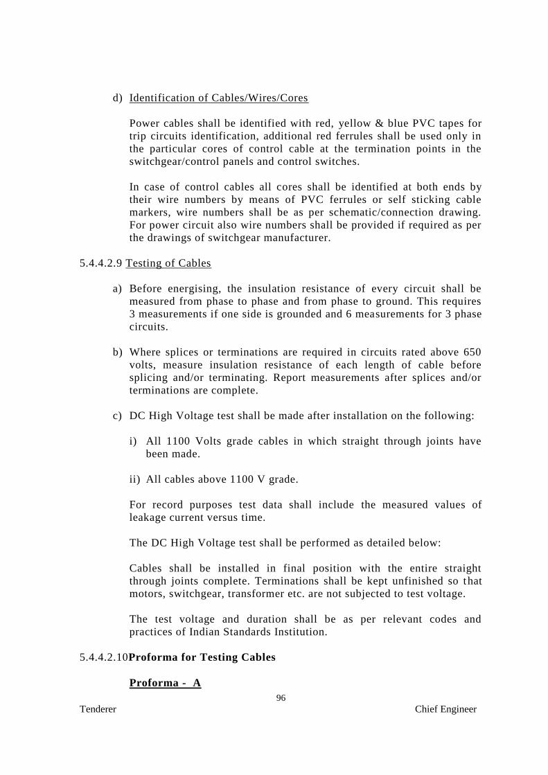
96
Tenderer Chief Engineer
d) Identification of Cables/Wires/Cores
Power cables shall be identified with red, yellow & blue PVC tapes for
trip circuits identification, additional red ferrules shall be used only in
the particular cores of control cable at the termination points in the
switchgear/control panels and control switches.
In case of control cables all cores shall be identified at both ends by
their wire numbers by means of PVC ferrules or self sticking cable
markers, wire numbers shall be as per schematic/connection drawing.
For power circuit also wire numbers shall be provided if required as per
the drawings of switchgear manufacturer.
5.4.4.2.9 Testing of Cables
a) Before energising, the insulation resistance of every circuit shall be
measured from phase to phase and from phase to ground. This requires
3 measurements if one side is grounded and 6 measurements for 3 phase
circuits.
b) Where splices or terminations are required in circuits rated above 650
volts, measure insulation resistance of each length of cable before
splicing and/or terminating. Report measurements after splices and/or
terminations are complete.
c) DC High Voltage test shall be made after installation on the following:
i) All 1100 Volts grade cables in which straight through joints have
been made.
ii) All cables above 1100 V grade.
For record purposes test data shall include the measured values of
leakage current versus time.
The DC High Voltage test shall be performed as detailed below:
Cables shall be installed in final position with the entire straight
through joints complete. Terminations shall be kept unfinished so that
motors, switchgear, transformer etc. are not subjected to test voltage.
The test voltage and duration shall be as per relevant codes and
practices of Indian Standards Institution.
5.4.4.2.10Proforma for Testing Cables
Proforma - A

97
Tenderer Chief Engineer
Date of Test
a) Drum No. from which cable taken
b) Cable from to
c) Length of run of this table metre
d) Insulation resistance test :
Voltage of Megger ...….. Volts
i) between core-1 to earth...... Megaohm
ii) between core-2 to earth...... Megaohm
iii) between core-3 to earth...... Megaohm
iv) between core-1 to core-2..... Megaohm
v) between core-2 to core-3..... Megaohm
vi) between core-3 to core-1..... Megaohm
e) High voltage test Voltage Duration
i) between cores and earth
ii) between individual cores
Signature of Signature of
Engineer-in-Charge Contractor
Proforma - B
Cable Laying
(To be shown for each cable separately, voltage wise)
Date(s) of Test:..............
Voltage of Megger used:...............
——————————————————————————————
Continuity IR value (mega ohm)
of cores ———————————————————————
Before laying Before back filling
—————— ———————
Between value Between Value
——————————————————————————————
1) From........……….To....…………......PVC/XLPE..…..x..…..sq.mm
LV/MV/HV cable..………….......m in length.

98
Tenderer Chief Engineer
R-N R-N
Y-N Y-N
B-N B-N
R-Y R-Y
B-R B-R
Y-B Y-B
R-E R-E
Y-E Y-E
B-E B-E
Signature of Signature of
Engineer-in-Charge Contractor
Proforma – C
Cable Jointing
(To be shown for each cable separately, voltage wise)
Date(s) of Test:..............
Voltage of Megger used:...............
1 2 3
Number of Joint
Location
Type of cable(s)
Type of joint (Indoor/Outdoor, straight
through/termination, LV/MV/HV)
Insulation resistance (Mega ohm) before jointing
Cable I - (a) Between R & Y
Y & B
B & R
(b) Between R & N
Y & N
B & N
(c) Between R & E
Y & E
B & E
N & E
Cable II - (a) Between R & Y
Y & B
B & R

99
Tenderer Chief Engineer
(b) Between R & N
Y & N
B & N
(c) Between R & E
Y & E
B & E
N & E
Insulation resistance (Mega ohm) of Jointed cable
Cable I - (a) Between R & Y
Y & B
B & R
(b) Between R & N
Y & N
B & N
(c) Between R & E
Y & E
B & E
N & E
Signature of Signature of
Engineer-in-Charge Contractor
Proforma - D
Testing Before Commissioning
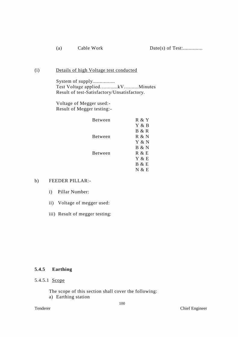
100
Tenderer Chief Engineer
(a) Cable Work Date(s) of Test:..............
(i) Details of high Voltage test conducted
System of supply................
Test Voltage applied….........kV….......Minutes
Result of test-Satisfactory/Unsatisfactory.
Voltage of Megger used:-
Result of Megger testing:-
Between R & Y
Y & B
B & R
Between R & N
Y & N
B & N
Between R & E
Y & E
B & E
N & E
b) FEEDER PILLAR:-
i) Pillar Number:
ii) Voltage of megger used:
iii) Result of megger testing:
5.4.5 Earthing
5.4.5.1 Scope
The scope of this section shall cover the following:
a) Earthing station

101
Tenderer Chief Engineer
b) Earthing conductors
c) Earthing of equipment and installation
5.4.5.2 Standards
The following standards shall be applicable:
IS : 3043 COP for earthing
IS : 5216 Safety procedures & practice in electrical work
5.4.5.3 Earth Station
The earth station shall be made by excavating the ground to a depth of
not less than 2.5 m and the excess earth after back filling shall be
removed from site. Ground with rocky strata, the depth of excavation
shall be less. However additional earthing stations or earth matting to
be provided to achieve the system earthing less than one ohm.
5.4.5.4 Electrodes
a) Various types of electrodes
i) Pipe electrode shall be buried in the ground vertically with its top at
not less than 20 cm below the ground level. The installation shall be
carried out as shown in the figure and as directed by the Engineer-
in-charge.
ii) Plate electrode shall be buried in ground with its face vertical, and
its top not less than 2 m below the ground level. The installation
shall be carried out as directed by the Engineer-in-charge.
iii) When more than one electrode is to be installed, the distance
between pipe electrodes shall be 5m and that between plates shall be
8m.
iv) a) The strip or conductor electrode shall be buried in trench not less
than 0.5 m deep.
b) If conditions necessitate the use of more than one strip or
conductor electrode, they shall be laid as widely distributed as
possible, in a single straight trench where feasible, or preferably
in a number of trenches radiating from one point or as directed
by the Engineer-in-charge.
5.4.5.5 Earthing Conductor (Main earthing lead)
The earth conductors shall be fixed to the wall/columns etc. at every
500 mm centres with 10 mm spacers. The total earthing system shall be

102
Tenderer Chief Engineer
mechanically and electrically connected to provide independent path to
earth.
i) In the case of plate earth electrode, the earthing conductor shall be
securely terminated on to the plate with two bolts, nuts, checknuts
and washers.
ii) A double C-clamp arrangement shall be provided for terminating
tape type earthing conductor with GI watering pipe coupled to the
pipe earth electrode. Galvanised “C” shaped strips, bolts, washers,
nuts and checknuts of adequate size shall be used for the purpose.
iii) The earthing conductor from the electrode upto the building shall be
protected from mechanical injury by a medium class, 15 mm dia. GI
pipe in the case of wire, and by 40 mm dia. medium class GI pipe in
the case of strip. The protection pipe in ground shall be buried
atleast 30 cm deep to be increased to 60 cm in case of road crossing
and pavements). The portion within the building shall be recessed
in walls and floors to adequate depth in due co-ordination with the
building work.
iv) The earthing conductor shall be securely connected at the other end
to the earth stud/earth bar provided on the switch board by bolt, nut
and washer.
5.4.5.6 Earth bus and main earthing terminal
i) The Main Earth bus shall be laid as directed by the Engineer-in-
charge.
ii) Following conductors shall be terminated into the main earthing
terminal/earth bus.
a) Earth connection from the Sub station.
b) Earthing conductor from electrode.
c) Protective conductors;
d) Equi-potential bonding conductors.
5.4.5.7 Protective (Loop earthing/earth continuity) Conductor
i) Earth terminal of every switch board in the distribution system shall
be bonded to the main earth bus.
103
Tenderer Chief Engineer
ii) Two protective conductors shall be provided for a switchboard.
iii) A protective conductor shall securely connect the ear th connector in
every distribution board (DB) to the earth bus.
iv) All metallic switch boxes and regulator boxes in a circuit shall be
connected to the earth connector in the DB by protective conductor.
v) The earth pin of socket outlets as well as metal lic body of fan
regulators shall be connected to the earth stud in switch boxes by
protective conductor.
5.4.5.8 Marking
i) Earth bars/terminals at all switch boards shall be marked permanently,
either as E or as
i) Main earth terminal shall be marked “Safety Earth – Do Not
Disconnect”.
Proforma for testing Earth Electrodes
i) Total number of earth electrodes...............
ii) Earth resistance of each earth electrode:
Sl.No. Location Value
Signature of Signature of
Engineer-in-Charge Contractor
5.4.6 MEASUREMENT
5.4.6.1 Quantities
The quantities set out in the Schedule of Requirements are the estimated
quantities of the work, but they are not to be taken as the actual and
exact quantities of the Work to be executed by the Contractor in
fulfilment of his obligations under the Contract.
5.4.6.2 Works to be measured
The Consultants shall, except as otherwise stated, ascertain and
determine by measurement the value in terms of the Contract of work
done in accordance with the Contract. He shall, when he required any
part or parts of the Work to be measured, give notice to the
Contractor’s authorised agent or representative, who shall forthwith
attend or send a qualified agent to assist the Engineer in making such
measurement, and shall furnish all particulars required by either of
them. Should the Contractor not attend, or neglect or omit to send such
agent, then the measurement made by the Engineer or agent approved

104
Tenderer Chief Engineer
by him shall be taken to be the correct measurement of the work. For
the purpose of measuring such permanent work as is to be measured by
records and drawings, the Consultant shall prepare records and drawing
month by month of such work and the Contractor, as and when called
upon to do so in writing, shall, within fourteen days, attend to examine
and agree such records and drawings with the Consultant and shall sign
the same when so agree such records and drawings, they shall be taken
to be correct. If, after examination of such records and drawings the
Contractor does not agree the same or does not sign the same as agreed,
they shall nevertheless be taken to be correct, unless the Contractor
shall, within fourteen days of such examination, lodge with the
Consultant, for decision by the Consultant, notice in writing of the
respects in which such records and drawing are claimed by him to be
incorrect.
5.4.6.3 Mode of Measurement
The Works shall be measured net, as prescribed in the specification of
work, notwithstanding any general or local custom, except where
otherwise specifically described or prescribed in the Contract.
Wherever not specifically mentioned in the Contract, the mode of
measurement as prescribed in the relevant IS codes shall be applicable
and binding to the Contract. Only the latest editions of all the codes of
practices including all latest official amendments and revisions shall be
applicable.
5.4.6.4 Battery Limit
Scope of work includes:
1. Cable laying, termination at both ends, testing & commissioning of
LT cables from DB to flood lights.
3. Earthing system includes supply, installation and testing of earth
pits and relevant earth conductors as per specification flood lights
etc.
4. Wherever buried cables are envisaged, scope of work includes
digging of earth along the cable route, filling up of sand protective
covering as per specification, laying of cable, covering the cables
with sand bricks, back filling of earth etc., as per specification.
Installation of Hume pipes including excavation, erection, back
filling etc. Cable markers shall be supplied & installed as per
specification.
5. The rates quoted for installation should include the charges for
painting the conduits & supports as directed by Purchaser/
Consultant.

105
Tenderer Chief Engineer
7. Supply, installation, testing and commissioning of flood lights.
8. Liaison with all statutory authorities including KSEB for getting
sanction/approval/safety certificate/ power connection including
submission of necessary forms to KSEB/ Electrical inspectorate
as required is included in the scope of this work. Necessary fee
for the above shall be reimbursed on production of actual bills.

106
Tenderer Chief Engineer
6.0 MAKE OF MATERIALS
6.1 Scope
The scope of this section covers the recommended makes of equipment,
material components. The final choice of makes shall be indicated at
the time of finalization of order.
The makes of material offered by the contractor shall be indicated at the
space provided for proper evaluation of the offer and shall be one of the
recommend makes. In the absence of such indication, the decision rests
with the Purchaser/consultant.
6.2 Makes recommended
The makes of material recommended are exhibited in respective section.
The offers shall be strictly on the basis of the makes recommended.
However, the bidders can offer alternative makes under deviation. Such
deviations shall follow with technical literature of the
material/equipment offered. Such deviation shall be considered only if
the offer is furnished for the specified make as per the tender.
Where specified make and model nos. are indicated in the schedule of
requirements, the bidder should quote for the same items.
6.3 LIST OF APPROVED MAKES OF EQUIPMENT AND
MATERIALS
Sl.No Item Make of Materials/Equipment
1 1.1 kV grade XLPE
insulated PVC sheathed
Al./ Cu. Cable
CCI, NICCO, Torrent, Universal, Havells, Gloster, V-
Guard
2 Cable glands, lugs, End termination kits
Lapp Kabel, Gripwel, HMI, Denson, Multipressings,
Yamuna Gasses.
3 Light fitting Philips, Wipro, Bajaj, Crompton, K-lite
4 Light pole Bajaj, Unique Pole, Metal Coats