Embed Size (px)
Citation preview
University of Groningen
Transition paths towards CO2 emission reduction in the steel industryDaniëls, Berend Wilhelm
IMPORTANT NOTE: You are advised to consult the publisher's version (publisher's PDF) if you wish to cite fromit. Please check the document version below.
Document VersionPublisher's PDF, also known as Version of record
Publication date:2002
Link to publication in University of Groningen/UMCG research database
Citation for published version (APA):Daniëls, B. W. (2002). Transition paths towards CO2 emission reduction in the steel industry Groningen:s.n.
CopyrightOther than for strictly personal use, it is not permitted to download or to forward/distribute the text or part of it without the consent of theauthor(s) and/or copyright holder(s), unless the work is under an open content license (like Creative Commons).
Take-down policyIf you believe that this document breaches copyright please contact us providing details, and we will remove access to the work immediatelyand investigate your claim.
Downloaded from the University of Groningen/UMCG research database (Pure): http://www.rug.nl/research/portal. For technical reasons thenumber of authors shown on this cover page is limited to 10 maximum.
Download date: 30-05-2018
4 Nowadays, removal of the sulphur generally takes place prior to the oxygen blowing, as the reduced state of thepig iron promotes the removal of the sulphur.
21
2 Steel Industry: Production Processes
2.1 IntroductionThe chapters 4 through 7 highlight various aspects of the introduction of new technologies.This chapter presents the technology data on existing and new technologies.
After a description of present technologies, and those available in the near future, thechapter gives an overview of production routes, based on a selection of the indicatedtechnologies. Tables present the data on the included processes, while the main textprovides more detailed, often technical information. In addition, text boxes providebackground information on some processes.
2.2 Basics of iron and steel productionSecondary, or scrap based, production of steel is very straightforward. Melting steel scrapresults in liquid steel, which can be shaped in the desired forms by casting, rolling andfinishing. However, scrap steel, both quantitatively and qualitatively, cannot meet the entiredemand for steel. Therefore, there is a continuing demand for primary steel.
In essence, all primary iron and steel production processes are based on the samechemical reactions. In iron ore, iron is presents in its oxidised form. In iron reductionprocesses, a reducing agent, based on carbon or hydrogen, removes the oxygen from theiron. This removal can take place either above or below the melting point of the ore and thereduced iron.
Reduction above the melting point results in pig iron. Above the melting point, most ofthe gangue materials segregate from the liquid iron, and float upon it. Because of the hightemperature and the liquid state of the iron, carbon readily dissolves in the pig iron,resulting in typical carbon contents between 4 and 6%. Reduction and dissolution of someof the gangue material may result in silicon and manganese contents of about 1%,depending on the ore composition and process conditions. In addition, pig iron containssome sulphur and phosphorus.
Oxygen blowing converts the pig iron to steel by oxidation of the carbon, silicon, andphosphorus. The carbon escapes mainly as carbon monoxide, while the oxidised silicon,sulphur4 and phosphorus segregate into the slag. This segregation process is enhanced byaddition of flux materials, such as lime.
Reduction below the melting point results in directly reduced iron (DRI), which retainsthe original shape of the ore, and includes the gangue material present in the ore. At thetemperature of reduction, the carbon of the reducing agent hardly dissolves in the iron,therefore DRI contains virtually no carbon. For conversion of DRI to steel, removal of thegangue material is necessary. Moreover, the carbon content has to be adjusted to therequired amount. Therefore, melting the DRI is necessary to convert the DRI to steel.
Although the chemical reactions involved in the various steel production methods arevery similar, steel producing installations and the flows therein are very different.Therefore, the various production routes have different demands with regard to resources.Iron ore occurs as lump ore and fine ore, and the latter is often processed into sinter orpellets. Both natural gas and coal are used as reducing agents. The blast furnace requires
22
the conversion of an important share of the coal to coke. The demands with regard to theresources, and necessary pre-processing steps strongly influence costs, energy-use andemissions of the various routes leading from ore to steel.
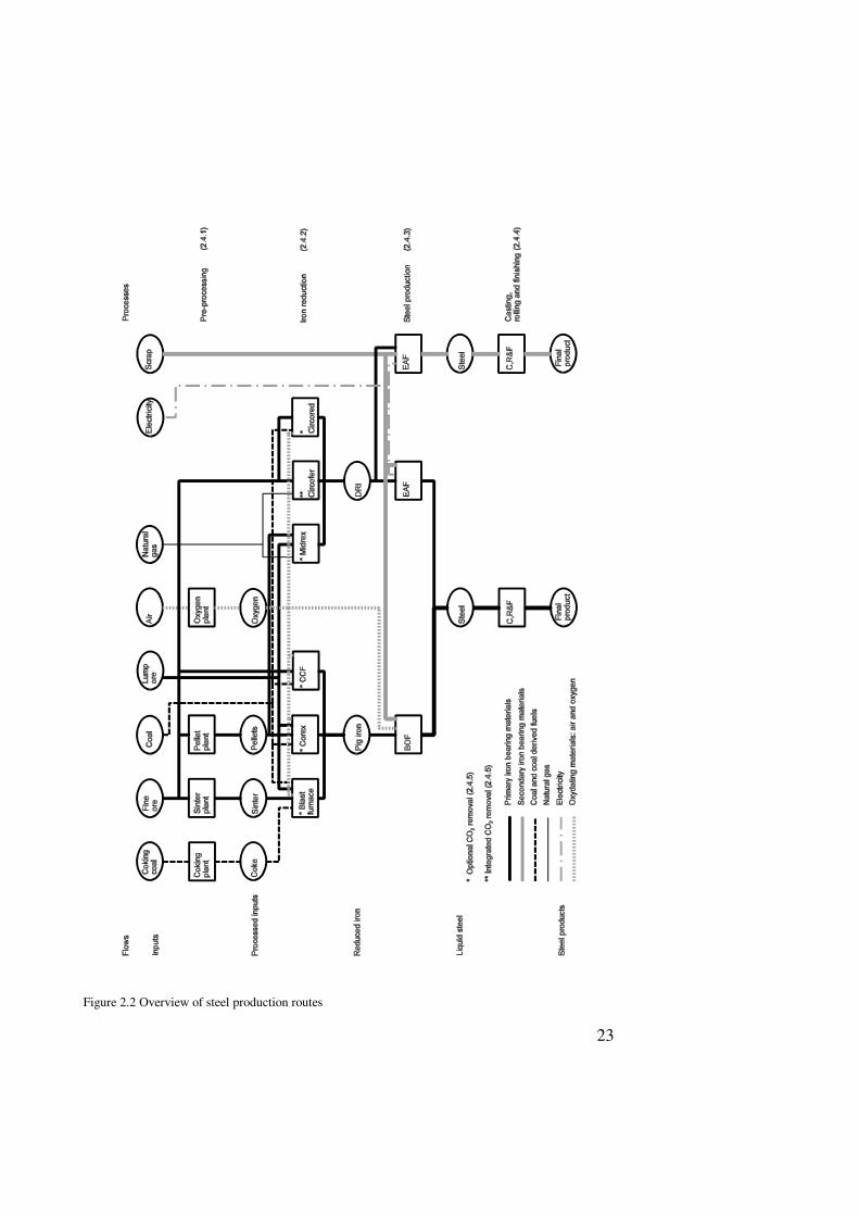
2.3 Production processesThis section gives an overview of some production technologies relevant for steelproduction. Besides established technologies, it includes recently introduced technologiesand those likely to be available within the next 25 years. The technologies have beencategorised according to their positions in the production chain, shown in figure 2.1. Thecategories are material preprocessing, iron reduction, steel production and casting, rollingand finishing.
Special attention is given to those process characteristics that play an important role inthe choice between different production processes. Apart from the basic data on costs andenergy consumption, these characteristics include the dependence on products of otherproduction processes. Such dependence has important consequences for the overall plantlayout, and for the attractiveness to switch to other processes. The technologies that are thebasis for the analyses in chapters 4 through 7 receive a detailed presentation in processtables. These present the labour input and the investment per tonne production capacity,and show ranges of input and output data. In addition, the proces tables specify the typicalvalues used in the analysis in chapter 4, which is based on fixed process characteristics.
The status of the typical values may differ strongly from values found in specific plants.The processes included are representations of types of production processes, andsubdivisions of these have not been listed separately. Where possible and relevant, the textpays attention to the range of process characteristics found in actual installations.
2.4 Process dataAs far as possible, process data originate from public data sources. For processes currentlyin use, Eurofer [10] has been an important source of economical and consumption data.Table 2.33 at the end of this chapter gives an overview of depreciation data according toEurofer. In case of contradictions between Eurofer and other sources, Eurofer datagenerally have prevailed, because of the depth of coverage of Eurofer and its WestEuropean focus. The Making, Shaping and Treating of Steel [39] has been a useful andimportant source for background information on processes and of more preciseconsumption data. For new processes, various more specialised sources have beenimportant. It was often necessary to fill gaps in the data by estimates based on the availableinformation on the respective processes and on comparable data from other processes. Theprocess data of all processes follow the format shown in box 2.1.
2.4.1 Preprocessing of raw materialsThe pre-processing of materials involve various processes that modify the characteristics ofmaterials such that they meet the demands of the main processes for iron reduction andsteel production. The reasons of pre-processing follow in the description of the mainprocesses. Pre-processing steps included are coke production, ore agglomeration andoxygen production.
23
Figure 2.2 Overview of steel production routes
24
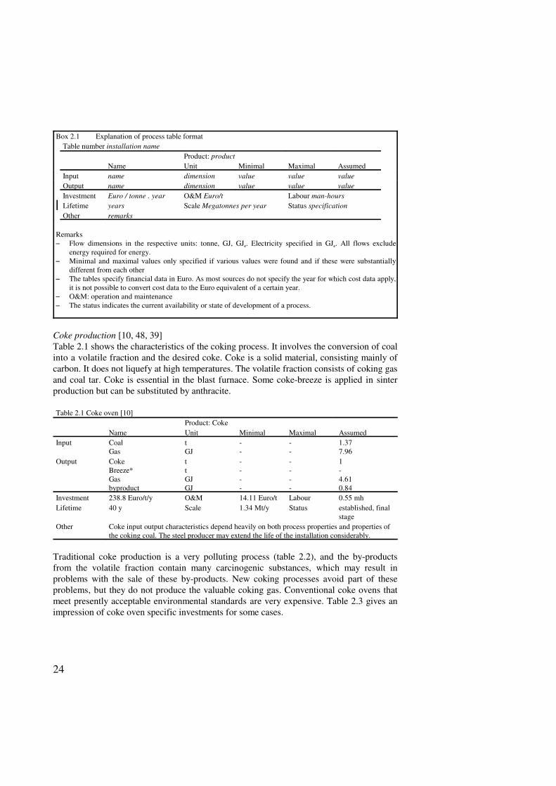
Box 2.1 Explanation of process table formatTable number installation name
Product: productName Unit Minimal Maximal Assumed
Input name dimension value value valueOutput name dimension value value valueInvestment Euro / tonne . year O&M Euro/t Labour man-hoursLifetime years Scale Megatonnes per year Status specificationOther remarks
Remarks6 Flow dimensions in the respective units: tonne, GJ, GJe. Electricity specified in GJe. All flows exclude
energy required for energy.6 Minimal and maximal values only specified if various values were found and if these were substantially
different from each other6 The tables specify financial data in Euro. As most sources do not specify the year for which cost data apply,
it is not possible to convert cost data to the Euro equivalent of a certain year. 6 O&M: operation and maintenance6 The status indicates the current availability or state of development of a process.
Coke production [10, 48, 39]Table 2.1 shows the characteristics of the coking process. It involves the conversion of coalinto a volatile fraction and the desired coke. Coke is a solid material, consisting mainly ofcarbon. It does not liquefy at high temperatures. The volatile fraction consists of coking gasand coal tar. Coke is essential in the blast furnace. Some coke-breeze is applied in sinterproduction but can be substituted by anthracite.
Table 2.1 Coke oven [10]Product: Coke
Name Unit Minimal Maximal AssumedInput Coal
GastGJ
--
--
1.377.96
Output CokeBreeze*Gasbyproduct
ttGJGJ
----
----
1-4.610.84
Investment 238.8 Euro/t/y O&M 14.11 Euro/t Labour 0.55 mhLifetime 40 y Scale 1.34 Mt/y Status established, final
stageOther Coke input output characteristics depend heavily on both process properties and properties of
the coking coal. The steel producer may extend the life of the installation considerably.
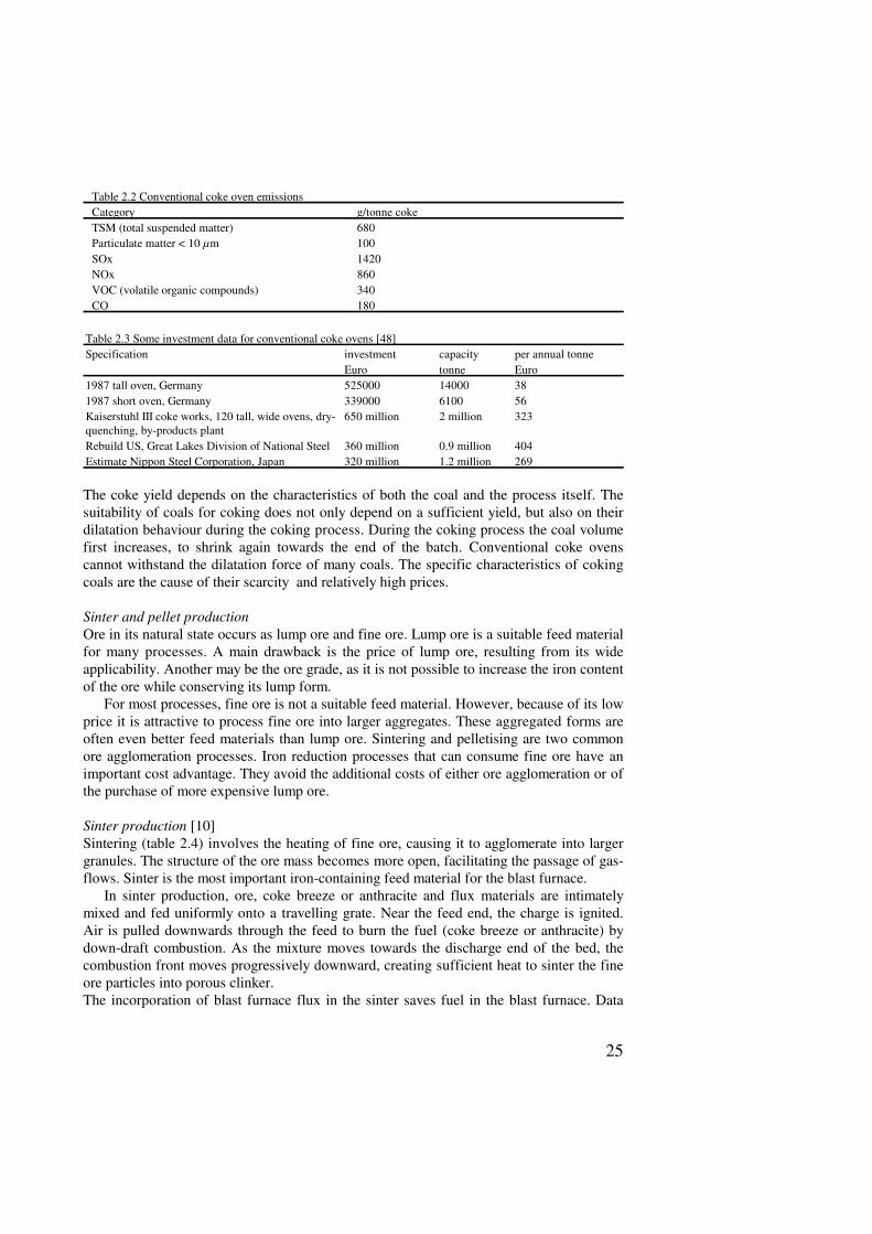
Traditional coke production is a very polluting process (table 2.2), and the by-productsfrom the volatile fraction contain many carcinogenic substances, which may result inproblems with the sale of these by-products. New coking processes avoid part of theseproblems, but they do not produce the valuable coking gas. Conventional coke ovens thatmeet presently acceptable environmental standards are very expensive. Table 2.3 gives animpression of coke oven specific investments for some cases.
25
Table 2.2 Conventional coke oven emissionsCategory g/tonne cokeTSM (total suspended matter) 680Particulate matter < 10 µm 100SOx 1420NOx 860VOC (volatile organic compounds) 340CO 180
Table 2.3 Some investment data for conventional coke ovens [48]Specification investment capacity per annual tonne
Euro tonne Euro1987 tall oven, Germany 525000 14000 381987 short oven, Germany 339000 6100 56Kaiserstuhl III coke works, 120 tall, wide ovens, dry-quenching, by-products plant
650 million 2 million 323
Rebuild US, Great Lakes Division of National Steel 360 million 0.9 million 404Estimate Nippon Steel Corporation, Japan 320 million 1.2 million 269
The coke yield depends on the characteristics of both the coal and the process itself. Thesuitability of coals for coking does not only depend on a sufficient yield, but also on theirdilatation behaviour during the coking process. During the coking process the coal volumefirst increases, to shrink again towards the end of the batch. Conventional coke ovenscannot withstand the dilatation force of many coals. The specific characteristics of cokingcoals are the cause of their scarcity and relatively high prices.
Sinter and pellet productionOre in its natural state occurs as lump ore and fine ore. Lump ore is a suitable feed materialfor many processes. A main drawback is the price of lump ore, resulting from its wideapplicability. Another may be the ore grade, as it is not possible to increase the iron contentof the ore while conserving its lump form.
For most processes, fine ore is not a suitable feed material. However, because of its lowprice it is attractive to process fine ore into larger aggregates. These aggregated forms areoften even better feed materials than lump ore. Sintering and pelletising are two commonore agglomeration processes. Iron reduction processes that can consume fine ore have animportant cost advantage. They avoid the additional costs of either ore agglomeration or ofthe purchase of more expensive lump ore.
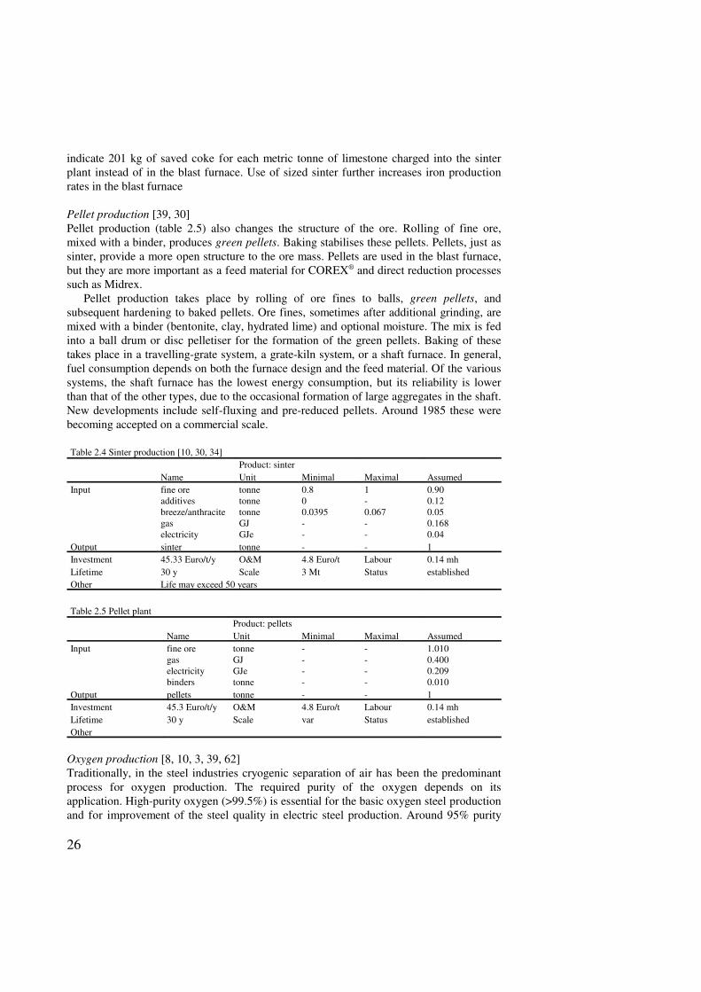
Sinter production [10]Sintering (table 2.4) involves the heating of fine ore, causing it to agglomerate into largergranules. The structure of the ore mass becomes more open, facilitating the passage of gas-flows. Sinter is the most important iron-containing feed material for the blast furnace.
In sinter production, ore, coke breeze or anthracite and flux materials are intimatelymixed and fed uniformly onto a travelling grate. Near the feed end, the charge is ignited.Air is pulled downwards through the feed to burn the fuel (coke breeze or anthracite) bydown-draft combustion. As the mixture moves towards the discharge end of the bed, thecombustion front moves progressively downward, creating sufficient heat to sinter the fineore particles into porous clinker.The incorporation of blast furnace flux in the sinter saves fuel in the blast furnace. Data
26
indicate 201 kg of saved coke for each metric tonne of limestone charged into the sinterplant instead of in the blast furnace. Use of sized sinter further increases iron productionrates in the blast furnace
Pellet production [39, 30]Pellet production (table 2.5) also changes the structure of the ore. Rolling of fine ore,mixed with a binder, produces green pellets. Baking stabilises these pellets. Pellets, just assinter, provide a more open structure to the ore mass. Pellets are used in the blast furnace,but they are more important as a feed material for COREX® and direct reduction processessuch as Midrex.
Pellet production takes place by rolling of ore fines to balls, green pellets, andsubsequent hardening to baked pellets. Ore fines, sometimes after additional grinding, aremixed with a binder (bentonite, clay, hydrated lime) and optional moisture. The mix is fedinto a ball drum or disc pelletiser for the formation of the green pellets. Baking of thesetakes place in a travelling-grate system, a grate-kiln system, or a shaft furnace. In general,fuel consumption depends on both the furnace design and the feed material. Of the varioussystems, the shaft furnace has the lowest energy consumption, but its reliability is lowerthan that of the other types, due to the occasional formation of large aggregates in the shaft.New developments include self-fluxing and pre-reduced pellets. Around 1985 these werebecoming accepted on a commercial scale.
Table 2.4 Sinter production [10, 30, 34]Product: sinter
Name Unit Minimal Maximal AssumedInput fine ore
additivesbreeze/anthracitegaselectricity
tonnetonnetonneGJGJe
0.800.0395--
1-0.067--
0.900.120.050.1680.04
Output sinter tonne - - 1Investment 45.33 Euro/t/y O&M 4.8 Euro/t Labour 0.14 mhLifetime 30 y Scale 3 Mt Status establishedOther Life may exceed 50 years
Table 2.5 Pellet plantProduct: pellets
Name Unit Minimal Maximal AssumedInput fine ore
gaselectricitybinders
tonneGJGJetonne
----
----
1.0100.4000.2090.010
Output pellets tonne - - 1Investment 45.3 Euro/t/y O&M 4.8 Euro/t Labour 0.14 mhLifetime 30 y Scale var Status establishedOther
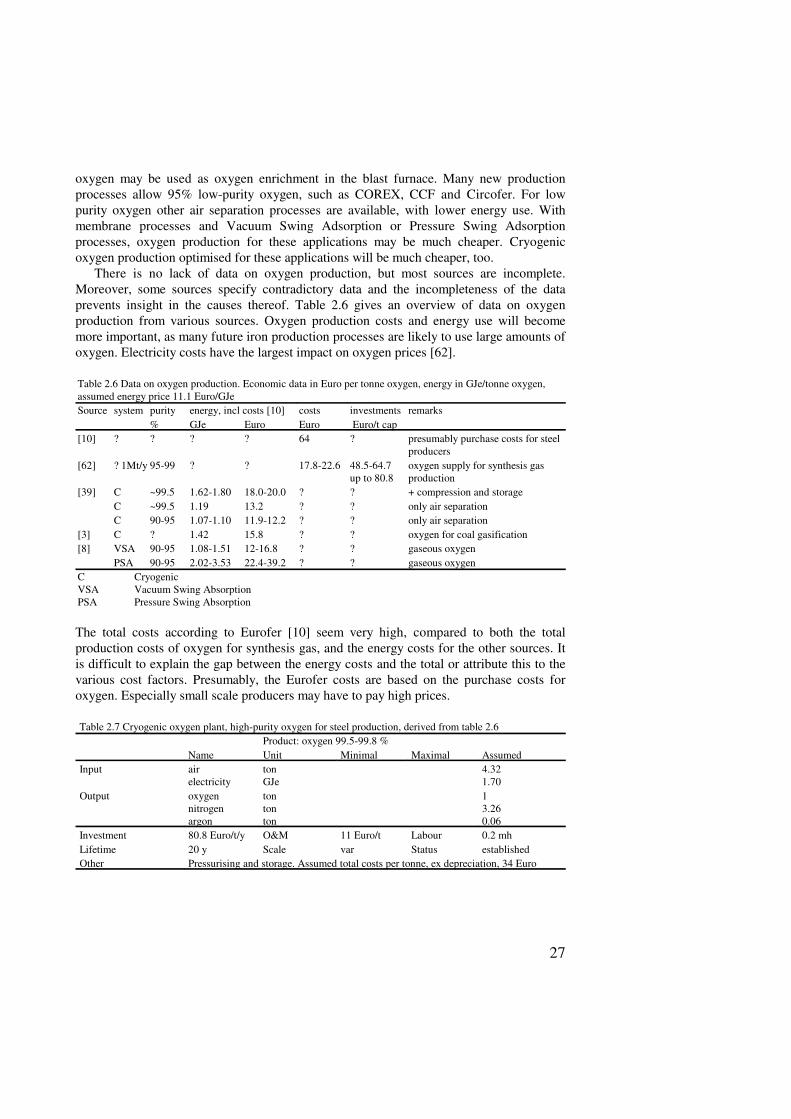
Oxygen production [8, 10, 3, 39, 62]Traditionally, in the steel industries cryogenic separation of air has been the predominantprocess for oxygen production. The required purity of the oxygen depends on itsapplication. High-purity oxygen (>99.5%) is essential for the basic oxygen steel productionand for improvement of the steel quality in electric steel production. Around 95% purity
27
oxygen may be used as oxygen enrichment in the blast furnace. Many new productionprocesses allow 95% low-purity oxygen, such as COREX, CCF and Circofer. For lowpurity oxygen other air separation processes are available, with lower energy use. Withmembrane processes and Vacuum Swing Adsorption or Pressure Swing Adsorptionprocesses, oxygen production for these applications may be much cheaper. Cryogenicoxygen production optimised for these applications will be much cheaper, too.
There is no lack of data on oxygen production, but most sources are incomplete.Moreover, some sources specify contradictory data and the incompleteness of the dataprevents insight in the causes thereof. Table 2.6 gives an overview of data on oxygenproduction from various sources. Oxygen production costs and energy use will becomemore important, as many future iron production processes are likely to use large amounts ofoxygen. Electricity costs have the largest impact on oxygen prices [62].
Table 2.6 Data on oxygen production. Economic data in Euro per tonne oxygen, energy in GJe/tonne oxygen,assumed energy price 11.1 Euro/GJe Source system purity energy, incl costs [10] costs investments remarks
% GJe Euro Euro Euro/t cap[10] ? ? ? ? 64 ? presumably purchase costs for steel
producers[62] ? 1Mt/y 95-99 ? ? 17.8-22.6 48.5-64.7
up to 80.8oxygen supply for synthesis gasproduction
[39] C ~99.5 1.62-1.80 18.0-20.0 ? ? + compression and storageC ~99.5 1.19 13.2 ? ? only air separationC 90-95 1.07-1.10 11.9-12.2 ? ? only air separation
[3] C ? 1.42 15.8 ? ? oxygen for coal gasification[8] VSA 90-95 1.08-1.51 12-16.8 ? ? gaseous oxygen
PSA 90-95 2.02-3.53 22.4-39.2 ? ? gaseous oxygenC CryogenicVSA Vacuum Swing AbsorptionPSA Pressure Swing Absorption
The total costs according to Eurofer [10] seem very high, compared to both the totalproduction costs of oxygen for synthesis gas, and the energy costs for the other sources. Itis difficult to explain the gap between the energy costs and the total or attribute this to thevarious cost factors. Presumably, the Eurofer costs are based on the purchase costs foroxygen. Especially small scale producers may have to pay high prices.
Table 2.7 Cryogenic oxygen plant, high-purity oxygen for steel production, derived from table 2.6Product: oxygen 99.5-99.8 %
Name Unit Minimal Maximal AssumedInput air
electricitytonGJe
4.321.70
Output oxygennitrogenargon
tontonton
13.260.06
Investment 80.8 Euro/t/y O&M 11 Euro/t Labour 0.2 mhLifetime 20 y Scale var Status establishedOther Pressurising and storage. Assumed total costs per tonne, ex depreciation, 34 Euro
28
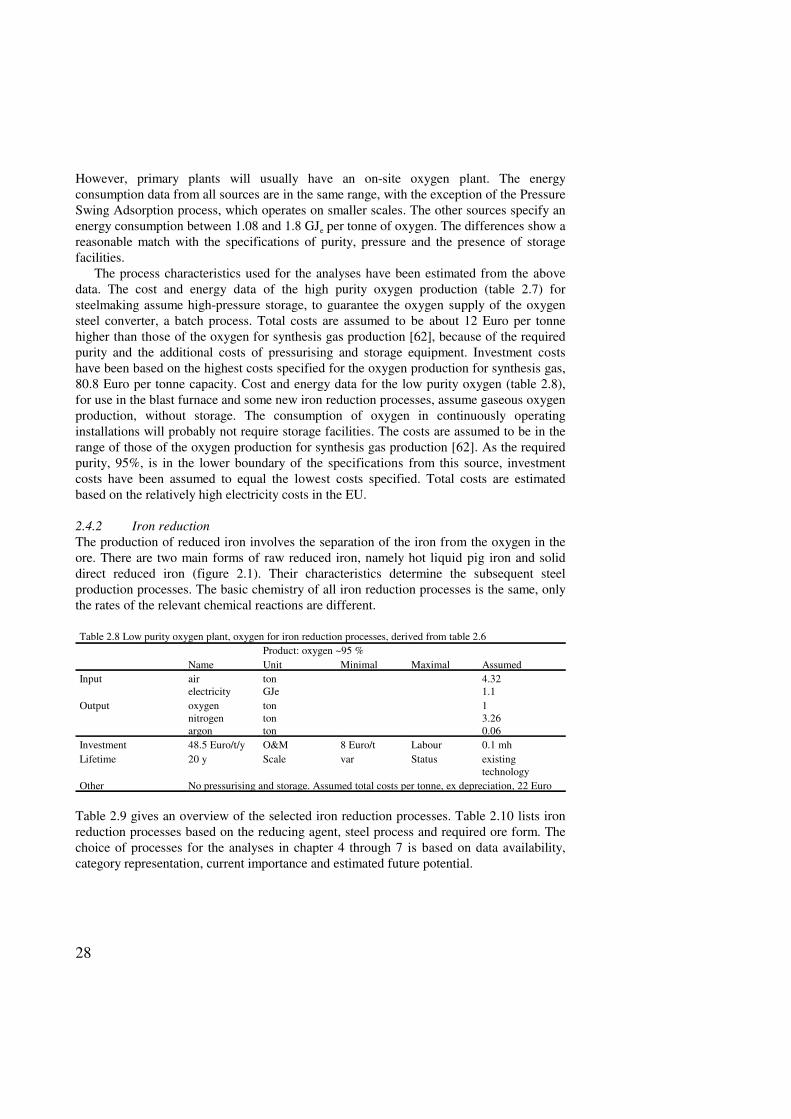
However, primary plants will usually have an on-site oxygen plant. The energyconsumption data from all sources are in the same range, with the exception of the PressureSwing Adsorption process, which operates on smaller scales. The other sources specify anenergy consumption between 1.08 and 1.8 GJe per tonne of oxygen. The differences show areasonable match with the specifications of purity, pressure and the presence of storagefacilities.
The process characteristics used for the analyses have been estimated from the abovedata. The cost and energy data of the high purity oxygen production (table 2.7) forsteelmaking assume high-pressure storage, to guarantee the oxygen supply of the oxygensteel converter, a batch process. Total costs are assumed to be about 12 Euro per tonnehigher than those of the oxygen for synthesis gas production [62], because of the requiredpurity and the additional costs of pressurising and storage equipment. Investment costshave been based on the highest costs specified for the oxygen production for synthesis gas,80.8 Euro per tonne capacity. Cost and energy data for the low purity oxygen (table 2.8),for use in the blast furnace and some new iron reduction processes, assume gaseous oxygenproduction, without storage. The consumption of oxygen in continuously operatinginstallations will probably not require storage facilities. The costs are assumed to be in therange of those of the oxygen production for synthesis gas production [62]. As the requiredpurity, 95%, is in the lower boundary of the specifications from this source, investmentcosts have been assumed to equal the lowest costs specified. Total costs are estimatedbased on the relatively high electricity costs in the EU.
2.4.2 Iron reductionThe production of reduced iron involves the separation of the iron from the oxygen in theore. There are two main forms of raw reduced iron, namely hot liquid pig iron and soliddirect reduced iron (figure 2.1). Their characteristics determine the subsequent steelproduction processes. The basic chemistry of all iron reduction processes is the same, onlythe rates of the relevant chemical reactions are different.
Table 2.8 Low purity oxygen plant, oxygen for iron reduction processes, derived from table 2.6Product: oxygen ~95 %
Name Unit Minimal Maximal AssumedInput air
electricitytonGJe
4.321.1
Output oxygennitrogenargon
tontonton
13.260.06
Investment 48.5 Euro/t/y O&M 8 Euro/t Labour 0.1 mhLifetime 20 y Scale var Status existing
technologyOther No pressurising and storage. Assumed total costs per tonne, ex depreciation, 22 Euro
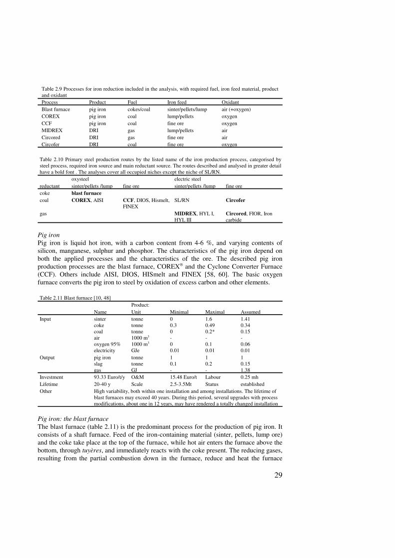
Table 2.9 gives an overview of the selected iron reduction processes. Table 2.10 lists ironreduction processes based on the reducing agent, steel process and required ore form. Thechoice of processes for the analyses in chapter 4 through 7 is based on data availability,category representation, current importance and estimated future potential.
29
Table 2.9 Processes for iron reduction included in the analysis, with required fuel, iron feed material, productand oxidantProcess Product Fuel Iron feed OxidantBlast furnace pig iron cokes/coal sinter/pellets/lump air (+oxygen)COREX pig iron coal lump/pellets oxygenCCF pig iron coal fine ore oxygenMIDREX DRI gas lump/pellets airCircored DRI gas fine ore airCircofer DRI coal fine ore oxygen
Table 2.10 Primary steel production routes by the listed name of the iron production process, categorised bysteel process, required iron source and main reductant source. The routes described and analysed in greater detailhave a bold font . The analyses cover all occupied niches except the niche of SL/RN.
oxysteel electric steel reductant sinter/pellets /lump fine ore sinter/pellets /lump fine orecoke blast furnacecoal COREX, AISI CCF, DIOS, Hismelt,
FINEXSL/RN Circofer
gas MIDREX, HYL I,HYL III
Circored, FIOR, Ironcarbide
Pig ironPig iron is liquid hot iron, with a carbon content from 4-6 %, and varying contents ofsilicon, manganese, sulphur and phosphor. The characteristics of the pig iron depend onboth the applied processes and the characteristics of the ore. The described pig ironproduction processes are the blast furnace, COREX® and the Cyclone Converter Furnace(CCF). Others include AISI, DIOS, HISmelt and FINEX [58, 60]. The basic oxygenfurnace converts the pig iron to steel by oxidation of excess carbon and other elements.
Table 2.11 Blast furnace [10, 48]Product:
Name Unit Minimal Maximal AssumedInput sinter
cokecoalairoxygen 95%electricity
tonnetonnetonne1000 m3
1000 m3
GJe
00.30-00.01
1.60.490.2*-0.10.01
1.410.340.15-0.060.01
Output pig ironslaggas
tonnetonneGJ
10.1-
10.2-
10.151.38
Investment 93.33 Euro/t/y O&M 15.48 Euro/t Labour 0.25 mhLifetime 20-40 y Scale 2.5-3.5Mt Status establishedOther High variability, both within one installation and among installations. The lifetime of
blast furnaces may exceed 40 years. During this period, several upgrades with processmodifications, about one in 12 years, may have rendered a totally changed installation
Pig iron: the blast furnaceThe blast furnace (table 2.11) is the predominant process for the production of pig iron. Itconsists of a shaft furnace. Feed of the iron-containing material (sinter, pellets, lump ore)and the coke take place at the top of the furnace, while hot air enters the furnace above thebottom, through tuyères, and immediately reacts with the coke present. The reducing gases,resulting from the partial combustion down in the furnace, reduce and heat the furnace
30
burden that descends slowly, as a result of the combustion of coke and the periodic tappingof fluid iron and slag down in the furnace. Combustion of part of the top gas, with anenergy content of about 3 MJ/m3, heats the blast. About 1.4 GJ of gas per tonne hot metalis available for other applications.
The countercurrent movement of the furnace burden and gases requires sufficientpermeability of the furnace burden. This is why coke and sinter (lump ore) are the requiredfeed materials instead of coal and fine ore. The burden, consisting of sinter and coke, has aporous structure. Down in the oven, where the ore melts, coke is the only solid providingboth the necessary permeability and the structural strength to support the furnace burden.
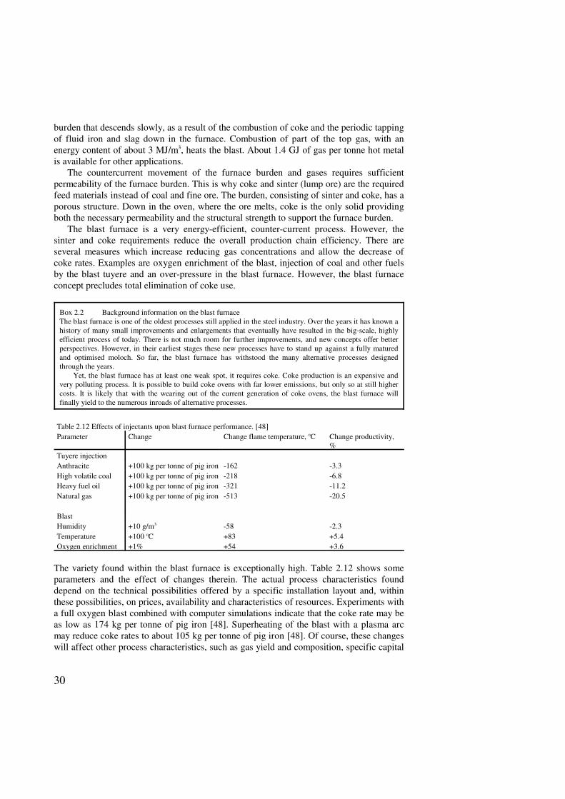
The blast furnace is a very energy-efficient, counter-current process. However, thesinter and coke requirements reduce the overall production chain efficiency. There areseveral measures which increase reducing gas concentrations and allow the decrease ofcoke rates. Examples are oxygen enrichment of the blast, injection of coal and other fuelsby the blast tuyere and an over-pressure in the blast furnace. However, the blast furnaceconcept precludes total elimination of coke use.
Box 2.2 Background information on the blast furnaceThe blast furnace is one of the oldest processes still applied in the steel industry. Over the years it has known ahistory of many small improvements and enlargements that eventually have resulted in the big-scale, highlyefficient process of today. There is not much room for further improvements, and new concepts offer betterperspectives. However, in their earliest stages these new processes have to stand up against a fully maturedand optimised moloch. So far, the blast furnace has withstood the many alternative processes designedthrough the years.
Yet, the blast furnace has at least one weak spot, it requires coke. Coke production is an expensive andvery polluting process. It is possible to build coke ovens with far lower emissions, but only so at still highercosts. It is likely that with the wearing out of the current generation of coke ovens, the blast furnace willfinally yield to the numerous inroads of alternative processes.
Table 2.12 Effects of injectants upon blast furnace performance. [48]Parameter Change Change flame temperature, oC Change productivity,
%Tuyere injectionAnthracite +100 kg per tonne of pig iron -162 -3.3High volatile coal +100 kg per tonne of pig iron -218 -6.8Heavy fuel oil +100 kg per tonne of pig iron -321 -11.2Natural gas +100 kg per tonne of pig iron -513 -20.5
BlastHumidity +10 g/m3 -58 -2.3Temperature +100 oC +83 +5.4Oxygen enrichment +1% +54 +3.6
The variety found within the blast furnace is exceptionally high. Table 2.12 shows someparameters and the effect of changes therein. The actual process characteristics founddepend on the technical possibilities offered by a specific installation layout and, withinthese possibilities, on prices, availability and characteristics of resources. Experiments witha full oxygen blast combined with computer simulations indicate that the coke rate may beas low as 174 kg per tonne of pig iron [48]. Superheating of the blast with a plasma arcmay reduce coke rates to about 105 kg per tonne of pig iron [48]. Of course, these changeswill affect other process characteristics, such as gas yield and composition, specific capital
31
costs, furnace wear, pig iron characteristics and others. Capital costs of coke substitutionequal are a fourth to a fifth of that corresponding with the replaced coke [48].
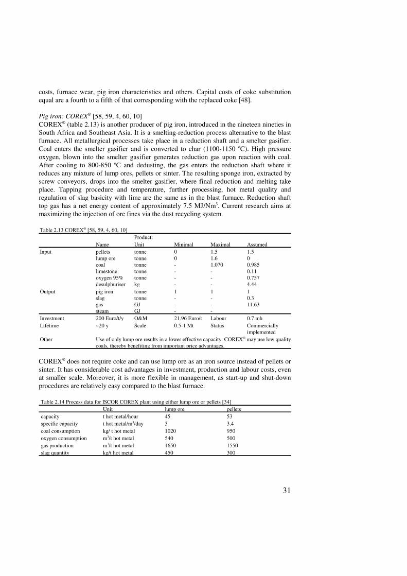
Pig iron: COREX® [58, 59, 4, 60, 10]COREX® (table 2.13) is another producer of pig iron, introduced in the nineteen nineties inSouth Africa and Southeast Asia. It is a smelting-reduction process alternative to the blastfurnace. All metallurgical processes take place in a reduction shaft and a smelter gasifier.Coal enters the smelter gasifier and is converted to char (1100-1150 oC). High pressureoxygen, blown into the smelter gasifier generates reduction gas upon reaction with coal.After cooling to 800-850 oC and dedusting, the gas enters the reduction shaft where itreduces any mixture of lump ores, pellets or sinter. The resulting sponge iron, extracted byscrew conveyors, drops into the smelter gasifier, where final reduction and melting takeplace. Tapping procedure and temperature, further processing, hot metal quality andregulation of slag basicity with lime are the same as in the blast furnace. Reduction shafttop gas has a net energy content of approximately 7.5 MJ/Nm3. Current research aims atmaximizing the injection of ore fines via the dust recycling system.
Table 2.13 COREX® [58, 59, 4, 60, 10]Product:
Name Unit Minimal Maximal AssumedInput pellets
lump orecoallimestoneoxygen 95%desulphuriser
tonnetonnetonnetonnetonnekg
00----
1.51.61.070---
1.500.9850.110.7574.44
Output pig ironslaggassteam
tonnetonneGJGJ
1---
1---
10.311.63
Investment 200 Euro/t/y O&M 21.96 Euro/t Labour 0.7 mhLifetime ~20 y Scale 0.5-1 Mt Status Commercially
implementedOther Use of only lump ore results in a lower effective capacity. COREX® may use low quality
coals, thereby benefiting from important price advantages.
COREX® does not require coke and can use lump ore as an iron source instead of pellets orsinter. It has considerable cost advantages in investment, production and labour costs, evenat smaller scale. Moreover, it is more flexible in management, as start-up and shut-downprocedures are relatively easy compared to the blast furnace.
Table 2.14 Process data for ISCOR COREX plant using either lump ore or pellets [34]Unit lump ore pellets
capacity t hot metal/hour 45 53specific capacity t hot metal/m3/day 3 3.4coal consumption kg/ t hot metal 1020 950oxygen consumption m3/t hot metal 540 500gas production m3/t hot metal 1650 1550slag quantity kg/t hot metal 450 300
32
Box 2.3 Background information on COREX®
The history of COREX® dates back to 1975, when R. Weber invented the concept. In 1977 there were alreadypilot plant tests. In 1979, there was an cooperation agreement between VOEST-ALPINE and Korf Stahl. 1981saw 11 test campaigns, and in 1985, VA, which in 1983 acquired all COREX® rights, had a contract withPOSCO ltd for the construction of a COREX® plant. The start-up of this plant was in 1989. After this, from1992 to 1995, there were five additional contracts for six COREX® plants. By the end of 1998, sevenCOREX® modules will be operational on five locations in South-Africa, Korea and India. So far, it is the onlynew pig iron process that has reached the stage of commercial introduction, even if only outside Europe.COREX® pig iron is comparable with blast furnace pig iron, and problems with use of the pig iron in steel-making are not likely.
COREX® is especially competitive in areas with demand for excess energy: it is essentially a coal gasifierwith pig iron as a by-product. The gas, with its high calorific value, can be used in a Midrex plant to reduceiron ore to DRI. In Korea, a site with two COREX® plants, one Midrex plants and two EAFs, completed in1997, is operational.
The costs advantages reported for COREX®, of 18 to 38%, are based on a comparison with the local,small scale blast furnaces. Its advantages in Western-Europe, where is has to compete with modern, large-scale blast furnace are probably smaller. However, VOEST expects that the cost advantage will increase froma current 20% to a future 25%, due to learning effects. COREX® already has the advantage that the emissionsof dust, NOx, SOx and others, are much lower than those of the blast furnace route with its coke ovens. WhenEuropean steel producers have to choose between the construction of new coke ovens, with expensivemeasures to reduce emissions, or the construction of COREX® plants, this will certainly favour COREX®.plants.
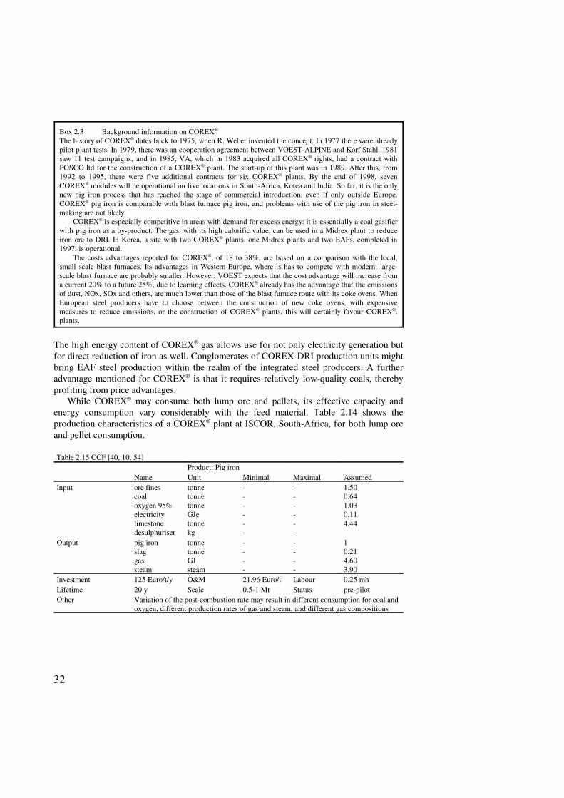
The high energy content of COREX® gas allows use for not only electricity generation butfor direct reduction of iron as well. Conglomerates of COREX-DRI production units mightbring EAF steel production within the realm of the integrated steel producers. A furtheradvantage mentioned for COREX® is that it requires relatively low-quality coals, therebyprofiting from price advantages.
While COREX® may consume both lump ore and pellets, its effective capacity andenergy consumption vary considerably with the feed material. Table 2.14 shows theproduction characteristics of a COREX® plant at ISCOR, South-Africa, for both lump oreand pellet consumption.
Table 2.15 CCF [40, 10, 54]Product: Pig iron
Name Unit Minimal Maximal AssumedInput ore fines
coaloxygen 95%electricitylimestonedesulphuriser
tonnetonnetonneGJetonnekg
------
------
1.500.641.030.114.44
Output pig ironslaggassteam
tonnetonneGJsteam
----
----
10.214.603.90
Investment 125 Euro/t/y O&M 21.96 Euro/t Labour 0.25 mhLifetime 20 y Scale 0.5-1 Mt Status pre-pilotOther Variation of the post-combustion rate may result in different consumption for coal and
oxygen, different production rates of gas and steam, and different gas compositions
33
Box 2.4 CCF background [54, 40]Almost 10 years of research in coal based iron-making preceded the first large scale trials. In this period, theHoogovens company cooperated with British Steel and Ilva. It is still in a semi-industrial stage: onlycomponents of the CCF have been operational in small scale tests. CCF consists of a converter-type vessel, themore conventional part and the cyclone, which is much more innovative. The small-scale tests concentratedon the cyclone part. Hoogovens already received a subsidy from the European Union to proceed with a CCFproduction plant with 500 kt annual capacity, showing the recognition of CCF as a promising technology toreduce CO2 emissions in steel production. Then however, Hoogovens terminated the further development ofCCF as they could not find industrial partners; the further development might be reinitiated when the cokeovens were worn out. CORUS, the product of the recent merger of Hoogovens and British Steel apparently hasno plans for a further development of CCF.
CCF requires coke nor pellets or lump ore. This results in considerable cost advantages in both operationand investment. Implementation of CCF will result in much smaller steel production sites, as coke ovens andore agglomeration plants are not necessary. Its simple design, with all reactions taking place in a single vessel,results in simple operation and short start-up and shut-down procedures. Apart from its lower CO2 emissions,it also has lower emissions of dust, NOx, SOx and other pollutants.
Although promising, CCF currently is stuck in the pilot stage. COREX, its direct competitor, is ready forintroduction onto the European market, having proved itself as a commercially viable pig iron produceroutside Europe. When CCF enters the market, it may face an improved COREX® process, benefiting from thelearning effects of more than a decade of use.
Pig iron: Cyclone Converter Furnace [40, 10, 54]The CCF (table 2.15) is a single reactor smelting-reduction process, capable of using orefines instead of lump ore, pellets or sinter. The reactor consists of a converter type vessel,with the melting cyclone on top. Ore and oxygen are injected tangentially into the meltingcyclone. The molten, pre-reduced ore is collected on the water-cooled wall, and descendsinto the iron bath. About 25% post-combustion with 80% heat recovery provides the heatrequired for the final reduction of the ore and the gasification of the granular coal. Furthercombustion to a final combustion rate of 75% takes place in the melting cyclone, togenerate melting and pre-reduction heat. On its way out of the cyclone, the gas passes asteam boiler, the steam of which can be applied for oxygen production and electricitygeneration.
The relative simplicity of the processing in a single reactor offers several advantages.Pre-reduction and final reduction are directly connected. Intermediate steps for gasconditioning, such as cooling, de-dusting and reforming, are not necessary.
DRIDirect reduced iron, or DRI, is a solid material, obtained by reduction of the iron ore belowits melting point. The electric arc furnace may convert the DRI to steel, melting the DRI toremove the included gangue. Addition of carbon to the desired level and oxidation ofundesired elements allows manipulation of the steel properties. DRI may also be used inthe basic oxygen furnace, instead of scrap or ore. The three DR-processes included areMIDREX, Circored® and Circofer. Others include SL/RN, Fastmet, HYL I and HYL III,FIOR and the iron carbide process.
34
Box 2.5 Midrex backgroundAt present, Midrex is an established DR technology. It produces about two thirds of world DRI. Capacityconcentrates in areas where cheap natural gas is available as a by-product of oil production. Generally, inthese areas without a market for the gas, the gas is flared. Often, it profits from the presence of ore, too.
These specific circumstances do not guarantee that MIDREX and similar technologies have a brightfuture in western countries, with their established industries and much higher gas prices. DRI is an attractiveproduct for dilution of scrap in the EAF, but its current niche is widely different from the West Europeanconditions.
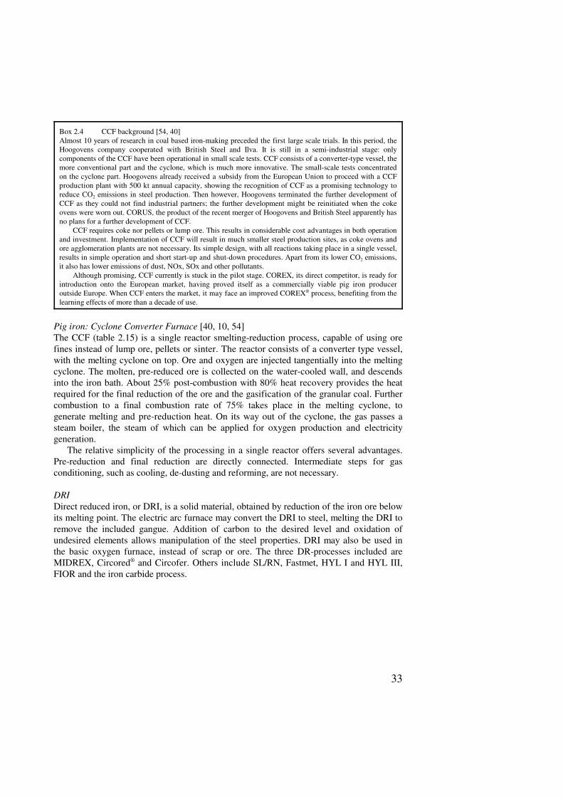
DRI: MIDREX [37, 39]MIDREX (table 2.16) is the most common DRI production process, accounting for abouttwo thirds of world DRI production in 1993. The shaft furnace requires lump ore or pelletsto provide charge porosity. Plants currently in operation use natural gas, but the processwould accept gas from a coal gasifier, as is the case in the combined COREX®-Midrexinstallation [60]. Other DR-processes using gas and lump ore or pellets are HYLI andHYLIII [37, 39].
Natural gas and top gas, after reaction in a catalytic reformer, yield a reducing gasmixture rich in CO and H2. Burning of a part of the top gas provides heat for the reformingprocess. Overall, the reactions in the shaft are slightly endothermic, heat being provided bythe heat of the reducing gas. Raw material enters the shaft at the top, reduction gas entersthe shaft at some distance from the bottom. In the upper part of the shaft reduction takesplace, lower down the shaft the charge is cooled and carbonised by cooling gas, obtainedfrom the shaft.
Table 2.16 MidrexProduct: DRI
Name Unit Minimal Maximal AssumedInput Lump ore
PelletsGasElectricity
tonnetonneGJGJe
00--
1.51.5--
0.870.6310.20.114
Output DRI tonne - - 1Investment 250 Euro/t/y O&M 22 Euro/t Labour 0.25 mhLifetime 20 y Scale 1 Mt Status establishedOther
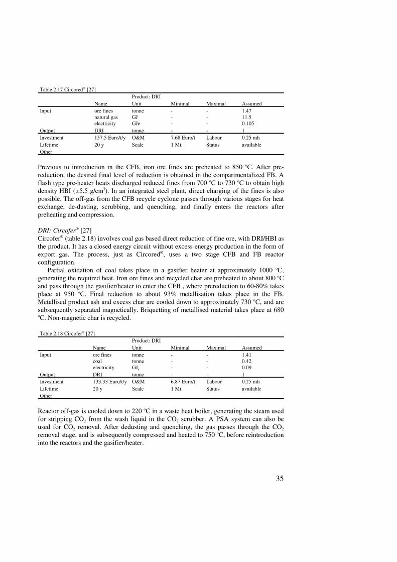
DRI: Circored® [27]Circored® (table 2.17) involves natural gas-based direct reduction of fine ore, with DRI asthe product, optionally in the form of hot briquetted iron (HBI). The process, just asCircofer®, uses a two stage CFB (circulating fluidised bed) and FB (fluidised bubbling bed)reactor configuration. Pre-reduction to 60-80% takes place in the CFB. A metallisationdegree of 93% is achieved during up to four hours retention in the FB reactor.
Circored® uses hydrogen, obtained from natural gas reforming, or from any other sourceas the reducing agent. Iron ore fines do not display a “sticking” tendency at the reductiontemperatures in the CFB, which are below 650 oC. An operating pressure of four bar isused because of the high process gas volumes required at these temperatures.
35
Table 2.17 Circored® [27]Product: DRI
Name Unit Minimal Maximal AssumedInput ore fines
natural gaselectricity
tonneGJGJe
---
---
1.4711.50.105
Output DRI tonne - - 1Investment 157.5 Euro/t/y O&M 7.68 Euro/t Labour 0.25 mhLifetime 20 y Scale 1 Mt Status availableOther
Previous to introduction in the CFB, iron ore fines are preheated to 850 oC. After pre-reduction, the desired final level of reduction is obtained in the compartmentalized FB. Aflash type pre-heater heats discharged reduced fines from 700 oC to 730 oC to obtain highdensity HBI (�5.5 g/cm3). In an integrated steel plant, direct charging of the fines is alsopossible. The off-gas from the CFB recycle cyclone passes through various stages for heatexchange, de-dusting, scrubbing, and quenching, and finally enters the reactors afterpreheating and compression.
DRI: Circofer® [27]Circofer® (table 2.18) involves coal gas based direct reduction of fine ore, with DRI/HBI asthe product. It has a closed energy circuit without excess energy production in the form ofexport gas. The process, just as Circored®, uses a two stage CFB and FB reactorconfiguration.
Partial oxidation of coal takes place in a gasifier heater at approximately 1000 oC,generating the required heat. Iron ore fines and recycled char are preheated to about 800 oCand pass through the gasifier/heater to enter the CFB , where prereduction to 60-80% takesplace at 950 oC. Final reduction to about 93% metallisation takes place in the FB.Metallised product ash and excess char are cooled down to approximately 730 oC, and aresubsequently separated magnetically. Briquetting of metallised material takes place at 680oC. Non-magnetic char is recycled.
Table 2.18 Circofer® [27]Product: DRI
Name Unit Minimal Maximal AssumedInput ore fines
coalelectricity
tonnetonneGJe
---
---
1.410.420.09
Output DRI tonne - - 1Investment 133.33 Euro/t/y O&M 6.87 Euro/t Labour 0.25 mhLifetime 20 y Scale 1 Mt Status availableOther
Reactor off-gas is cooled down to 220 oC in a waste heat boiler, generating the steam usedfor stripping CO2 from the wash liquid in the CO2 scrubber. A PSA system can also beused for CO2 removal. After dedusting and quenching, the gas passes through the CO2
removal stage, and is subsequently compressed and heated to 750 oC, before reintroductioninto the reactors and the gasifier/heater.
36
Box 2.6 Background information on Circored® and Circofer®
These DR technologies both avoid the costs of expensive lump ore or ore agglomeration. As they are bothdeveloped by LURGI technologies and use similar technologies, it is appropriate to treat them both in thisbox.
Apart from the reductant source, Circored® and Circofer® are very similar. Even the production costs,calculated by Lurgi for a West-Australian location, are nearly the same. The actual production cost differencesbetween the processes will depend mainly on the prices of coal and natural gas, and it is here that Circofer®
has the strongest cards for Europe. The assumed coal price is slightly lower than the European price, but thegas price is much lower, US$ 1.80 per GJ instead of the European value of 2.87 Euro per GJ. Therefore, itseems likely that in the near future Circored® will be confined to the same niche as that of Midrex, whileCircofer, depending on much easier transportable, globally priced coal, will have better chances in theindustrialised countries.
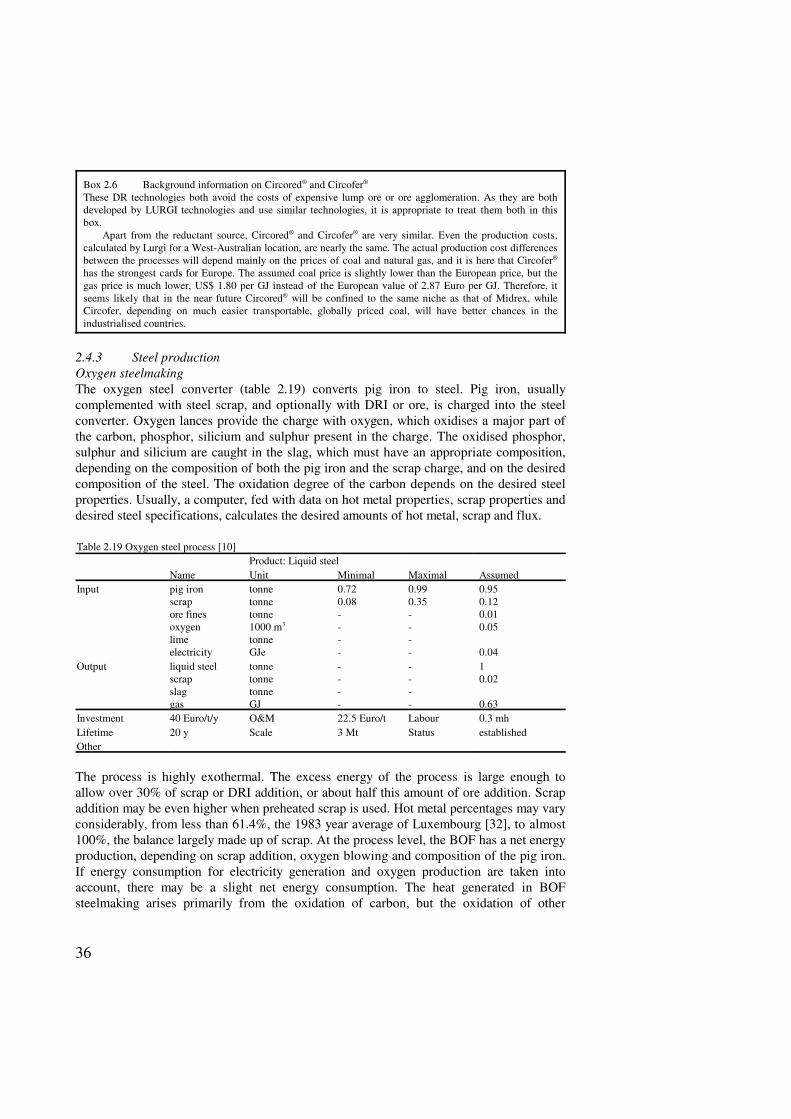
2.4.3 Steel productionOxygen steelmakingThe oxygen steel converter (table 2.19) converts pig iron to steel. Pig iron, usuallycomplemented with steel scrap, and optionally with DRI or ore, is charged into the steelconverter. Oxygen lances provide the charge with oxygen, which oxidises a major part ofthe carbon, phosphor, silicium and sulphur present in the charge. The oxidised phosphor,sulphur and silicium are caught in the slag, which must have an appropriate composition,depending on the composition of both the pig iron and the scrap charge, and on the desiredcomposition of the steel. The oxidation degree of the carbon depends on the desired steelproperties. Usually, a computer, fed with data on hot metal properties, scrap properties anddesired steel specifications, calculates the desired amounts of hot metal, scrap and flux.
Table 2.19 Oxygen steel process [10]Product: Liquid steel
Name Unit Minimal Maximal AssumedInput pig iron
scrapore finesoxygenlimeelectricity
tonnetonnetonne1000 m3
tonneGJe
0.720.08----
0.990.35----
0.950.120.010.05
0.04Output liquid steel
scrapslaggas
tonnetonnetonneGJ
----
----
10.02
0.63Investment 40 Euro/t/y O&M 22.5 Euro/t Labour 0.3 mhLifetime 20 y Scale 3 Mt Status establishedOther
The process is highly exothermal. The excess energy of the process is large enough toallow over 30% of scrap or DRI addition, or about half this amount of ore addition. Scrapaddition may be even higher when preheated scrap is used. Hot metal percentages may varyconsiderably, from less than 61.4%, the 1983 year average of Luxembourg [32], to almost100%, the balance largely made up of scrap. At the process level, the BOF has a net energyproduction, depending on scrap addition, oxygen blowing and composition of the pig iron.If energy consumption for electricity generation and oxygen production are taken intoaccount, there may be a slight net energy consumption. The heat generated in BOFsteelmaking arises primarily from the oxidation of carbon, but the oxidation of other
37
substances, especially silicon, is also important. Therefore, the charge compositiondetermines the maximum amount of heat generated.
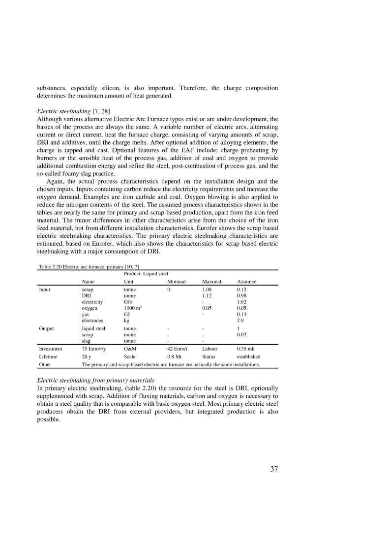
Electric steelmaking [7, 28]Although various alternative Electric Arc Furnace types exist or are under development, thebasics of the process are always the same. A variable number of electric arcs, alternatingcurrent or direct current, heat the furnace charge, consisting of varying amounts of scrap,DRI and additives, until the charge melts. After optional addition of alloying elements, thecharge is tapped and cast. Optional features of the EAF include: charge preheating byburners or the sensible heat of the process gas, addition of coal and oxygen to provideadditional combustion energy and refine the steel, post-combustion of process gas, and theso-called foamy slag practice.
Again, the actual process characteristics depend on the installation design and thechosen inputs. Inputs containing carbon reduce the electricity requirements and increase theoxygen demand. Examples are iron carbide and coal. Oxygen blowing is also applied toreduce the nitrogen contents of the steel. The assumed process characteristics shown in thetables are nearly the same for primary and scrap-based production, apart from the iron feedmaterial. The minor differences in other characteristics arise from the choice of the ironfeed material, not from different installation characteristics. Eurofer shows the scrap basedelectric steelmaking characteristics. The primary electric steelmaking characteristics areestimated, based on Eurofer, which also shows the characteristics for scrap based electricsteelmaking with a major consumption of DRI.
Table 2.20 Electric arc furnace, primary [10, 7]Product: Liquid steel
Name Unit Minimal Maximal AssumedInput scrap
DRIelectricityoxygengaselectrodes
tonnetonneGJe1000 m3
GJkg
0 1.081.12-0.05-
0.120.981.620.050.132.9
Output liquid steelscrapslag
tonnetonnetonne
---
---
10.02
Investment 75 Euro/t/y O&M 42 Euro/t Labour 0.35 mh
Lifetime 20 y Scale 0.8 Mt Status establishedOther The primary and scrap based electric arc furnace are basically the same installations.
Electric steelmaking from primary materialsIn primary electric steelmaking, (table 2.20) the resource for the steel is DRI, optionallysupplemented with scrap. Addition of fluxing materials, carbon and oxygen is necessary toobtain a steel quality that is comparable with basic oxygen steel. Most primary electric steelproducers obtain the DRI from external providers, but integrated production is alsopossible.
38
Table 2.21 Electric arc furnace, scrap [10]Product: Liquid steel
Name Unit Minimal Maximal AssumedInput scrap
DRIelectricityoxygengaselectrodes
tonnetonneGJe1000 m3
GJkg
0 1.081.12-0.05-
1.0801.260.050.132.9
Output liquid steelscrapslag
tonnetonnetonne
---
---
10.05
Investment 75 Euro/t/y O&M 31 Euro/t Labour 0.25 mh
Lifetime 20 y Scale 0.8 Mt Status establishedOther The primary and scrap based electric arc furnace are basically the same installations.
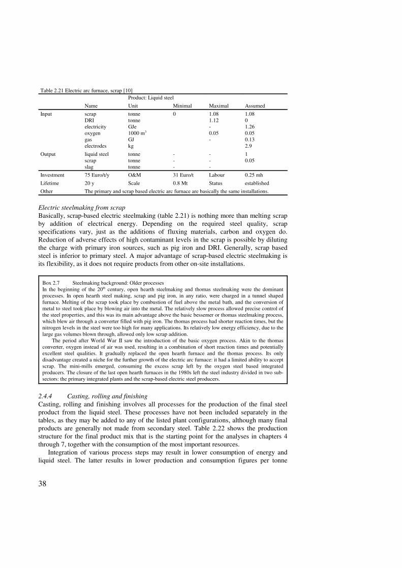
Electric steelmaking from scrapBasically, scrap-based electric steelmaking (table 2.21) is nothing more than melting scrapby addition of electrical energy. Depending on the required steel quality, scrapspecifications vary, just as the additions of fluxing materials, carbon and oxygen do.Reduction of adverse effects of high contaminant levels in the scrap is possible by dilutingthe charge with primary iron sources, such as pig iron and DRI. Generally, scrap basedsteel is inferior to primary steel. A major advantage of scrap-based electric steelmaking isits flexibility, as it does not require products from other on-site installations.
Box 2.7 Steelmaking background: Older processesIn the beginning of the 20th century, open hearth steelmaking and thomas steelmaking were the dominantprocesses. In open hearth steel making, scrap and pig iron, in any ratio, were charged in a tunnel shapedfurnace. Melting of the scrap took place by combustion of fuel above the metal bath, and the conversion ofmetal to steel took place by blowing air into the metal. The relatively slow process allowed precise control ofthe steel properties, and this was its main advantage above the basic bessemer or thomas steelmaking process,which blew air through a converter filled with pig iron. The thomas process had shorter reaction times, but thenitrogen levels in the steel were too high for many applications. Its relatively low energy efficiency, due to thelarge gas volumes blown through, allowed only low scrap addition.
The period after World War II saw the introduction of the basic oxygen process. Akin to the thomasconverter, oxygen instead of air was used, resulting in a combination of short reaction times and potentiallyexcellent steel qualities. It gradually replaced the open hearth furnace and the thomas process. Its onlydisadvantage created a niche for the further growth of the electric arc furnace: it had a limited ability to acceptscrap. The mini-mills emerged, consuming the excess scrap left by the oxygen steel based integratedproducers. The closure of the last open hearth furnaces in the 1980s left the steel industry divided in two sub-sectors: the primary integrated plants and the scrap-based electric steel producers.
2.4.4 Casting, rolling and finishingCasting, rolling and finishing involves all processes for the production of the final steelproduct from the liquid steel. These processes have not been included separately in thetables, as they may be added to any of the listed plant configurations, although many finalproducts are generally not made from secondary steel. Table 2.22 shows the productionstructure for the final product mix that is the starting point for the analyses in chapters 4through 7, together with the consumption of the most important resources.
Integration of various process steps may result in lower consumption of energy andliquid steel. The latter results in lower production and consumption figures per tonne
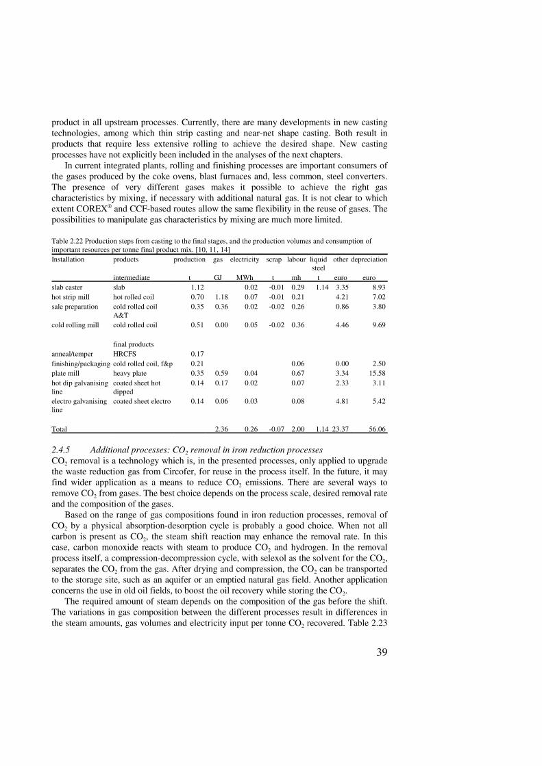
39
product in all upstream processes. Currently, there are many developments in new castingtechnologies, among which thin strip casting and near-net shape casting. Both result inproducts that require less extensive rolling to achieve the desired shape. New castingprocesses have not explicitly been included in the analyses of the next chapters.
In current integrated plants, rolling and finishing processes are important consumers ofthe gases produced by the coke ovens, blast furnaces and, less common, steel converters.The presence of very different gases makes it possible to achieve the right gascharacteristics by mixing, if necessary with additional natural gas. It is not clear to whichextent COREX® and CCF-based routes allow the same flexibility in the reuse of gases. Thepossibilities to manipulate gas characteristics by mixing are much more limited.
Table 2.22 Production steps from casting to the final stages, and the production volumes and consumption ofimportant resources per tonne final product mix. [10, 11, 14]Installation products production gas electricity scrap labour liquid
steelother depreciation
intermediate t GJ MWh t mh t euro euroslab caster slab 1.12 0.02 -0.01 0.29 1.14 3.35 8.93 hot strip mill hot rolled coil 0.70 1.18 0.07 -0.01 0.21 4.21 7.02 sale preparation cold rolled coil
A&T0.35 0.36 0.02 -0.02 0.26 0.86 3.80
cold rolling mill cold rolled coil 0.51 0.00 0.05 -0.02 0.36 4.46 9.69
final productsanneal/temper HRCFS 0.17 finishing/packaging cold rolled coil, f&p 0.21 0.06 0.00 2.50 plate mill heavy plate 0.35 0.59 0.04 0.67 3.34 15.58 hot dip galvanisingline
coated sheet hotdipped
0.14 0.17 0.02 0.07 2.33 3.11
electro galvanisingline
coated sheet electro 0.14 0.06 0.03 0.08 4.81 5.42
Total 2.36 0.26 -0.07 2.00 1.14 23.37 56.06
2.4.5 Additional processes: CO2 removal in iron reduction processesCO2 removal is a technology which is, in the presented processes, only applied to upgradethe waste reduction gas from Circofer, for reuse in the process itself. In the future, it mayfind wider application as a means to reduce CO2 emissions. There are several ways toremove CO2 from gases. The best choice depends on the process scale, desired removal rateand the composition of the gases.
Based on the range of gas compositions found in iron reduction processes, removal ofCO2 by a physical absorption-desorption cycle is probably a good choice. When not allcarbon is present as CO2, the steam shift reaction may enhance the removal rate. In thiscase, carbon monoxide reacts with steam to produce CO2 and hydrogen. In the removalprocess itself, a compression-decompression cycle, with selexol as the solvent for the CO2,separates the CO2 from the gas. After drying and compression, the CO2 can be transportedto the storage site, such as an aquifer or an emptied natural gas field. Another applicationconcerns the use in old oil fields, to boost the oil recovery while storing the CO2.
The required amount of steam depends on the composition of the gas before the shift.The variations in gas composition between the different processes result in differences inthe steam amounts, gas volumes and electricity input per tonne CO2 recovered. Table 2.23
40
Dried and preheated ore
CFBStage I
Fluid Bed Stage II
ProcessGas HeatExchanger
RecycleCyclone
Fuel, Air Fuel, AirFuel, Air
Solids
Gas
DRI
HBI
ProcessGasHeater
Scrubber
Multi Clone
gives an overview of the calculated characteristics of the CO2-removal processes for thevarious processes. The characteristics are based on the Integrated Coal Gasifier withremoval [24], adapted for the gas compositions for each process, with the help of physicaldata on the gas components [19].
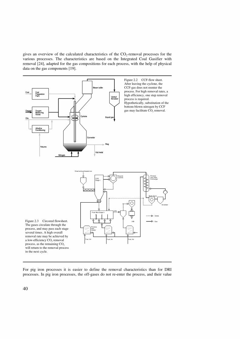
Figure 2.2 CCF-flow sheet.After leaving the cyclone, theCCF-gas does not reenter theprocess. For high removal rates, ahigh efficiency, one step removalprocess is required.Hypothetically, substitution of thebottom-blown nitrogen by CCFgas may facilitate CO2 removal.
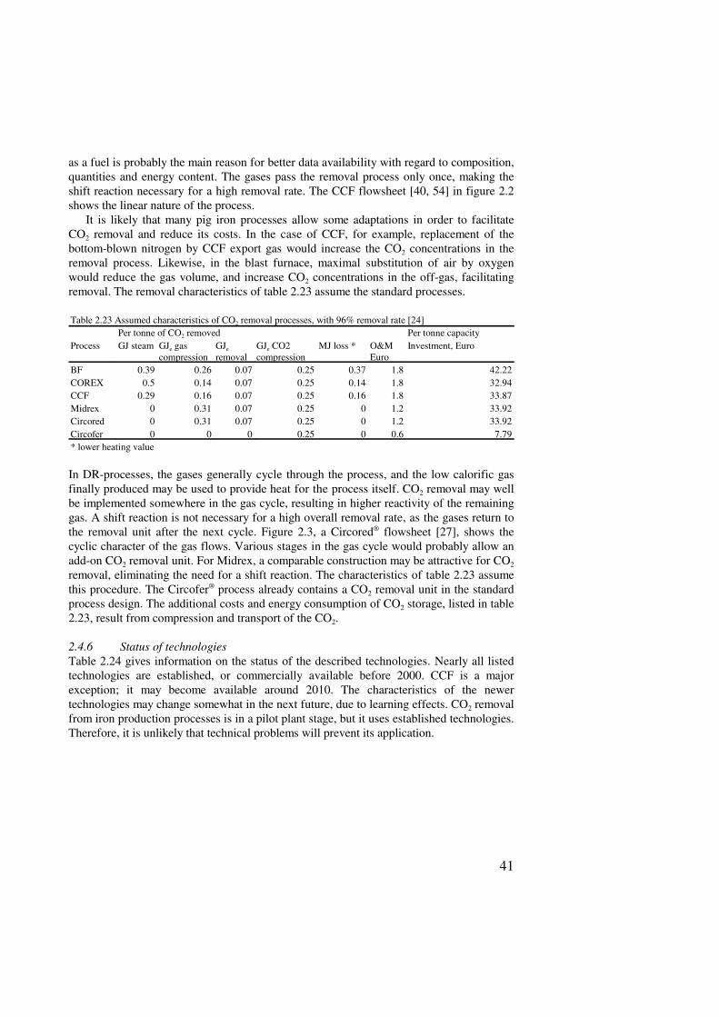
Figure 2.3 Circored flowsheet.The gases circulate through theprocess, and may pass each stageseveral times. A high overallremoval rate may be achieved bya low-efficiency CO2 removalprocess, as the remaining CO2
will return to the removal processin the next cycle.
For pig iron processes it is easier to define the removal characteristics than for DRIprocesses. In pig iron processes, the off-gases do not re-enter the process, and their value
41
as a fuel is probably the main reason for better data availability with regard to composition,quantities and energy content. The gases pass the removal process only once, making theshift reaction necessary for a high removal rate. The CCF flowsheet [40, 54] in figure 2.2shows the linear nature of the process.
It is likely that many pig iron processes allow some adaptations in order to facilitateCO2 removal and reduce its costs. In the case of CCF, for example, replacement of thebottom-blown nitrogen by CCF export gas would increase the CO2 concentrations in theremoval process. Likewise, in the blast furnace, maximal substitution of air by oxygenwould reduce the gas volume, and increase CO2 concentrations in the off-gas, facilitatingremoval. The removal characteristics of table 2.23 assume the standard processes.
Table 2.23 Assumed characteristics of CO2 removal processes, with 96% removal rate [24]Per tonne of CO2 removed Per tonne capacity
Process GJ steam GJe gascompression
GJe
removalGJe CO2compression
MJ loss * O&MEuro
Investment, Euro
BF 0.39 0.26 0.07 0.25 0.37 1.8 42.22COREX 0.5 0.14 0.07 0.25 0.14 1.8 32.94CCF 0.29 0.16 0.07 0.25 0.16 1.8 33.87Midrex 0 0.31 0.07 0.25 0 1.2 33.92Circored 0 0.31 0.07 0.25 0 1.2 33.92Circofer 0 0 0 0.25 0 0.6 7.79* lower heating value
In DR-processes, the gases generally cycle through the process, and the low calorific gasfinally produced may be used to provide heat for the process itself. CO2 removal may wellbe implemented somewhere in the gas cycle, resulting in higher reactivity of the remaininggas. A shift reaction is not necessary for a high overall removal rate, as the gases return tothe removal unit after the next cycle. Figure 2.3, a Circored® flowsheet [27], shows thecyclic character of the gas flows. Various stages in the gas cycle would probably allow anadd-on CO2 removal unit. For Midrex, a comparable construction may be attractive for CO2
removal, eliminating the need for a shift reaction. The characteristics of table 2.23 assumethis procedure. The Circofer® process already contains a CO2 removal unit in the standardprocess design. The additional costs and energy consumption of CO2 storage, listed in table2.23, result from compression and transport of the CO2.
2.4.6 Status of technologiesTable 2.24 gives information on the status of the described technologies. Nearly all listedtechnologies are established, or commercially available before 2000. CCF is a majorexception; it may become available around 2010. The characteristics of the newertechnologies may change somewhat in the next future, due to learning effects. CO2 removalfrom iron production processes is in a pilot plant stage, but it uses established technologies.Therefore, it is unlikely that technical problems will prevent its application.
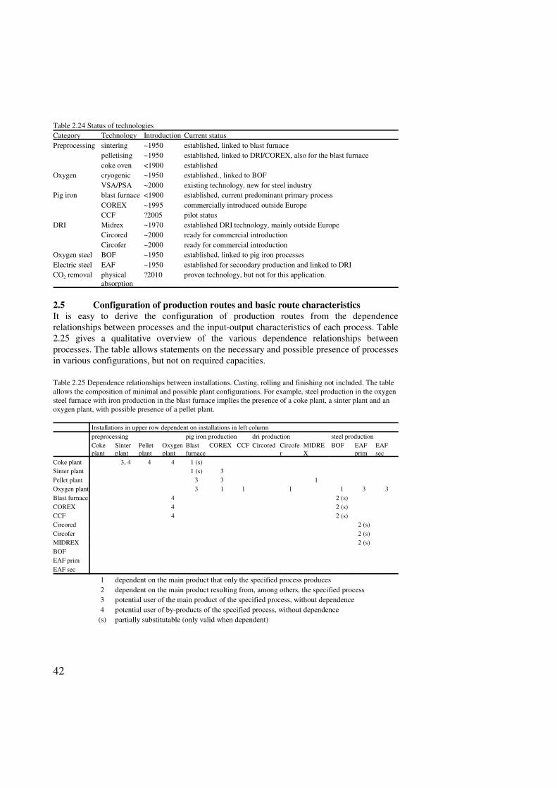
42
Table 2.24 Status of technologiesCategory Technology Introduction Current statusPreprocessing sintering ~1950 established, linked to blast furnace
pelletising ~1950 established, linked to DRI/COREX, also for the blast furnacecoke oven <1900 established
Oxygen cryogenic ~1950 established., linked to BOFVSA/PSA ~2000 existing technology, new for steel industry
Pig iron blast furnace <1900 established, current predominant primary processCOREX ~1995 commercially introduced outside EuropeCCF ?2005 pilot status
DRI Midrex ~1970 established DRI technology, mainly outside EuropeCircored ~2000 ready for commercial introductionCircofer ~2000 ready for commercial introduction
Oxygen steel BOF ~1950 established, linked to pig iron processesElectric steel EAF ~1950 established for secondary production and linked to DRI CO2 removal physical
absorption?2010 proven technology, but not for this application.
2.5 Configuration of production routes and basic route characteristicsIt is easy to derive the configuration of production routes from the dependencerelationships between processes and the input-output characteristics of each process. Table2.25 gives a qualitative overview of the various dependence relationships betweenprocesses. The table allows statements on the necessary and possible presence of processesin various configurations, but not on required capacities.
Table 2.25 Dependence relationships between installations. Casting, rolling and finishing not included. The tableallows the composition of minimal and possible plant configurations. For example, steel production in the oxygensteel furnace with iron production in the blast furnace implies the presence of a coke plant, a sinter plant and anoxygen plant, with possible presence of a pellet plant.
Installations in upper row dependent on installations in left column preprocessing pig iron production dri production steel productionCokeplant
Sinterplant
Pelletplant
Oxygenplant
Blastfurnace
COREX CCF Circored Circofer
MIDREX
BOF EAFprim
EAFsec
Coke plant 3, 4 4 4 1 (s)Sinter plant 1 (s) 3Pellet plant 3 3 1Oxygen plant 3 1 1 1 1 3 3Blast furnace 4 2 (s)COREX 4 2 (s)CCF 4 2 (s)Circored 2 (s)Circofer 2 (s)MIDREX 2 (s)BOFEAF primEAF sec
1 dependent on the main product that only the specified process produces2 dependent on the main product resulting from, among others, the specified process3 potential user of the main product of the specified process, without dependence4 potential user of by-products of the specified process, without dependence
(s) partially substitutable (only valid when dependent)
43
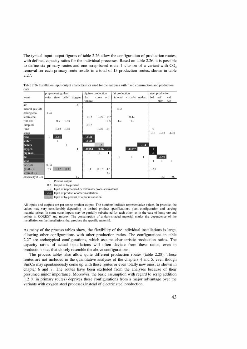
The typical input-output figures of table 2.26 allow the configuration of production routes,with defined capacity ratios for the individual processes. Based on table 2.26, it is possibleto define six primary routes and one scrap-based route. Inclusion of a variant with CO2
removal for each primary route results in a total of 13 production routes, shown in table2.27.
Table 2.26 Installation input-output characteristics used for the analyses with fixed consumption and productiondata
preprocessing plant pig iron production dri production steel productiontonne coke sinter pellet oxygen blast
furnacecorex ccf circored circofer midrex bof eaf
primeafsec
air -5natural gas(GJ) 11.2coking coal -1.37steam coal -0.15 -0.95 -0.7 0.42fine ore -0.9 -0.95 -1.5 -1.2 -1.2lump ore -0.16lime -0.12 -0.05 -0.05 -0.1 0scrap -0.1 -0.12 -1.08coke 1 -0.05 -0.34sinter 1 -1.41pellets 1 -1.5 -1.4oxygen 1 -0.084 -0.76 -1 -0.287 0pig iron 1 1 1 -1dri 1 1 1 -0.98steel 1 1 1tar (GJ) 0.84gas (GJ) 7.9 -0.17 -0.4 1.4 11.16 4.6 0.63steam (GJ) 3.9electricity (GJe) 1.7 1.62 1.26
1 Product output0.2 Output of by-product-0.2 Input of unprocessed or externally processed material-0.2 Input of product of other installation-0.2 Input of by-product of other installation
All inputs and outputs are per tonne product output. The numbers indicate representative values. In practice, thevalues may vary considerably depending on desired product specifications, plant configuration and varyingmaterial prices. In some cases inputs may be partially substituted for each other, as in the case of lump ore andpellets in COREX® and midrex. The consumption of a dark-shaded material marks the dependence of theinstallation on the installations that produce the specific material.
As many of the process tables show, the flexibility of the individual installations is large,allowing other configurations with other production ratios. The configurations in table2.27 are archetypical configurations, which assume charateristic production ratios. Thecapacity ratios of actual installations will often deviate from these ratios, even inproduction sites that closely resemble the above configurations.
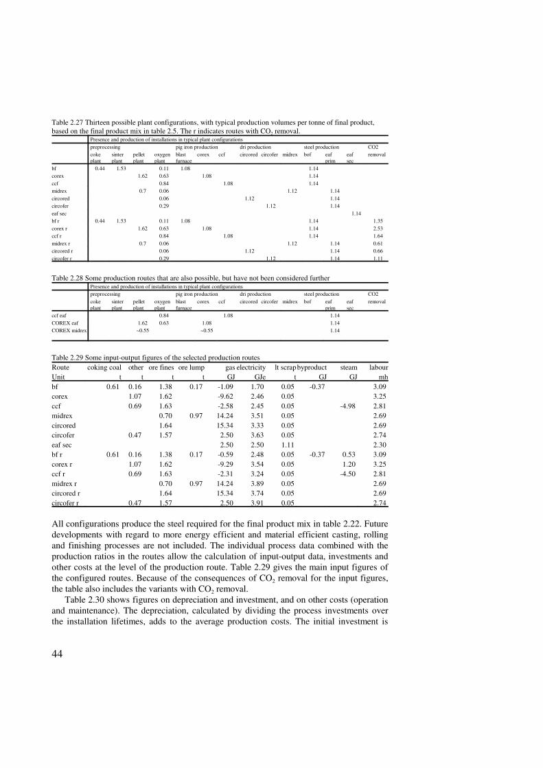
The process tables also allow quite different production routes (table 2.28). Theseroutes are not included in the quantitative analyses of the chapters 4 and 5, even thoughSimCo may spontaneously come up with these routes or even totally new ones, as shown inchapter 6 and 7. The routes have been excluded from the analyses because of theirpresumed minor importance. Moreover, the basic assumption with regard to scrap addition(12 % in primary routes) deprives these configurations from a major advantage over thevariants with oxygen steel processes instead of electric steel production.
44
Table 2.27 Thirteen possible plant configurations, with typical production volumes per tonne of final product,based on the final product mix in table 2.5. The r indicates routes with CO2 removal.
Presence and production of installations in typical plant configurationspreprocessing pig iron production dri production steel production CO2cokeplant
sinterplant
pelletplant
oxygenplant
blastfurnace
corex ccf circored circofer midrex bof eafprim
eafsec
removal
bf 0.44 1.53 0.11 1.08 1.14corex 1.62 0.63 1.08 1.14ccf 0.84 1.08 1.14midrex 0.7 0.06 1.12 1.14circored 0.06 1.12 1.14circofer 0.29 1.12 1.14eaf sec 1.14bf r 0.44 1.53 0.11 1.08 1.14 1.35corex r 1.62 0.63 1.08 1.14 2.53ccf r 0.84 1.08 1.14 1.64midrex r 0.7 0.06 1.12 1.14 0.61circored r 0.06 1.12 1.14 0.66circofer r 0.29 1.12 1.14 1.11
Table 2.28 Some production routes that are also possible, but have not been considered furtherPresence and production of installations in typical plant configurationspreprocessing pig iron production dri production steel production CO2cokeplant
sinterplant
pelletplant
oxygenplant
blastfurnace
corex ccf circored circofer midrex bof eafprim
eafsec
removal
ccf eaf 0.84 1.08 1.14COREX eaf 1.62 0.63 1.08 1.14COREX midrex ~0.55 ~0.55 1.14
Table 2.29 Some input-output figures of the selected production routesRoute coking coal other ore fines ore lump gas electricity lt scrapbyproduct steam labourUnit t t t t GJ GJe t GJ GJ mhbf 0.61 0.16 1.38 0.17 -1.09 1.70 0.05 -0.37 3.09 corex 1.07 1.62 -9.62 2.46 0.05 3.25 ccf 0.69 1.63 -2.58 2.45 0.05 -4.98 2.81 midrex 0.70 0.97 14.24 3.51 0.05 2.69 circored 1.64 15.34 3.33 0.05 2.69 circofer 0.47 1.57 2.50 3.63 0.05 2.74 eaf sec 2.50 2.50 1.11 2.30 bf r 0.61 0.16 1.38 0.17 -0.59 2.48 0.05 -0.37 0.53 3.09 corex r 1.07 1.62 -9.29 3.54 0.05 1.20 3.25 ccf r 0.69 1.63 -2.31 3.24 0.05 -4.50 2.81 midrex r 0.70 0.97 14.24 3.89 0.05 2.69 circored r 1.64 15.34 3.74 0.05 2.69 circofer r 0.47 1.57 2.50 3.91 0.05 2.74
All configurations produce the steel required for the final product mix in table 2.22. Futuredevelopments with regard to more energy efficient and material efficient casting, rollingand finishing processes are not included. The individual process data combined with theproduction ratios in the routes allow the calculation of input-output data, investments andother costs at the level of the production route. Table 2.29 gives the main input figures ofthe configured routes. Because of the consequences of CO2 removal for the input figures,the table also includes the variants with CO2 removal.
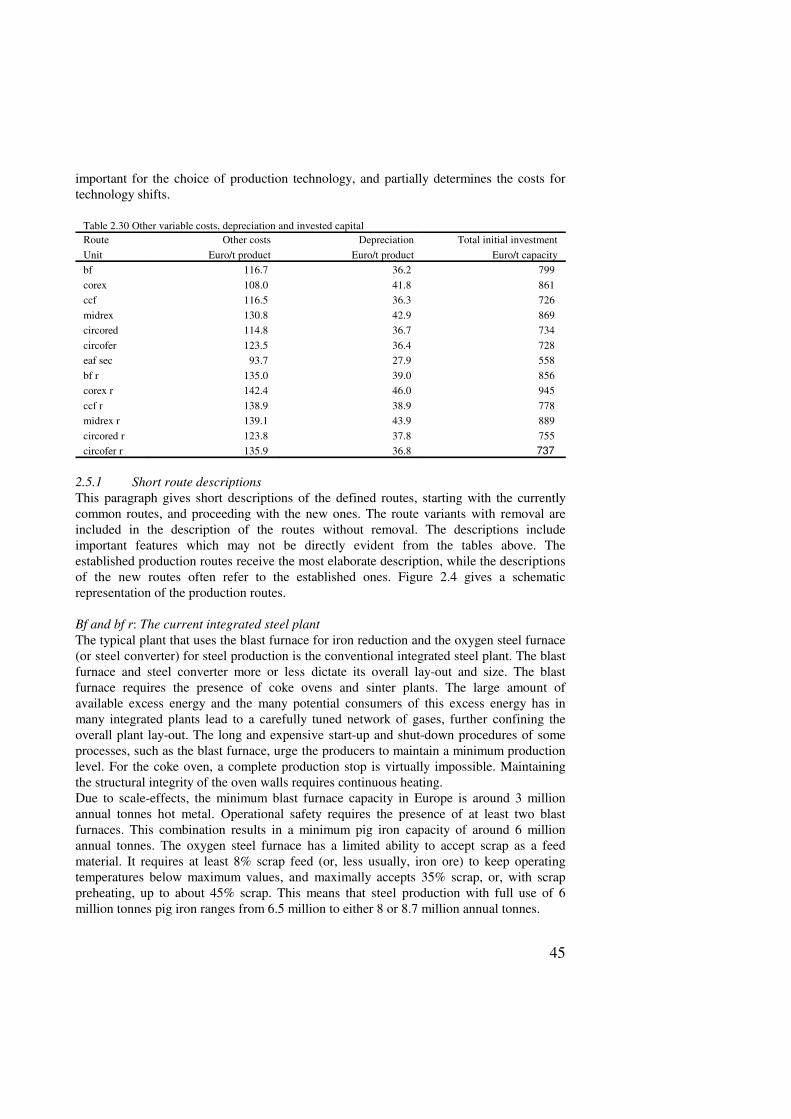
Table 2.30 shows figures on depreciation and investment, and on other costs (operationand maintenance). The depreciation, calculated by dividing the process investments overthe installation lifetimes, adds to the average production costs. The initial investment is
45
important for the choice of production technology, and partially determines the costs fortechnology shifts.
Table 2.30 Other variable costs, depreciation and invested capitalRoute Other costs Depreciation Total initial investmentUnit Euro/t product Euro/t product Euro/t capacitybf 116.7 36.2 799 corex 108.0 41.8 861 ccf 116.5 36.3 726 midrex 130.8 42.9 869 circored 114.8 36.7 734 circofer 123.5 36.4 728 eaf sec 93.7 27.9 558 bf r 135.0 39.0 856 corex r 142.4 46.0 945 ccf r 138.9 38.9 778 midrex r 139.1 43.9 889 circored r 123.8 37.8 755 circofer r 135.9 36.8 737
2.5.1 Short route descriptionsThis paragraph gives short descriptions of the defined routes, starting with the currentlycommon routes, and proceeding with the new ones. The route variants with removal areincluded in the description of the routes without removal. The descriptions includeimportant features which may not be directly evident from the tables above. Theestablished production routes receive the most elaborate description, while the descriptionsof the new routes often refer to the established ones. Figure 2.4 gives a schematicrepresentation of the production routes.
Bf and bf r: The current integrated steel plantThe typical plant that uses the blast furnace for iron reduction and the oxygen steel furnace(or steel converter) for steel production is the conventional integrated steel plant. The blastfurnace and steel converter more or less dictate its overall lay-out and size. The blastfurnace requires the presence of coke ovens and sinter plants. The large amount ofavailable excess energy and the many potential consumers of this excess energy has inmany integrated plants lead to a carefully tuned network of gases, further confining theoverall plant lay-out. The long and expensive start-up and shut-down procedures of someprocesses, such as the blast furnace, urge the producers to maintain a minimum productionlevel. For the coke oven, a complete production stop is virtually impossible. Maintainingthe structural integrity of the oven walls requires continuous heating.Due to scale-effects, the minimum blast furnace capacity in Europe is around 3 millionannual tonnes hot metal. Operational safety requires the presence of at least two blastfurnaces. This combination results in a minimum pig iron capacity of around 6 millionannual tonnes. The oxygen steel furnace has a limited ability to accept scrap as a feedmaterial. It requires at least 8% scrap feed (or, less usually, iron ore) to keep operatingtemperatures below maximum values, and maximally accepts 35% scrap, or, with scrappreheating, up to about 45% scrap. This means that steel production with full use of 6million tonnes pig iron ranges from 6.5 million to either 8 or 8.7 million annual tonnes.
46
The large scale of production and the wide applicability of the primary steel allow theintegrated plant to produce a wide range of products. The many different processes forcasting, rolling and finishing are important consumers of the excess energy. However, theyoften require gases with carefully tuned specifications. To meet the requirements of theprocesses, the operating company mixes the gases from the different sources, with eachother or with natural gas. An innovation affecting the gas balance of the company mayimpede or, on the contrary, facilitate balanced use of the gases.
The long production chain and the presence of many capital-extensive processes resultin a relatively large standing capital stock. Both entering and leaving the market isexpensive, as is a temporary production stop. Steel producers not only try to optimise theproduction side, but also the demand side. Integrated steel production presupposes long-term contracts and increasing vertical production chain integration.
It will be clear that the integrated plant is relatively inflexible with regard to the tuningof capacity to production. In many cases, some of the standing capacity will be unutilised,and increase of capacity by additional production units will be realised in relatively largesteps. Moreover, attractive innovations may lose some of their appeal if they disturb theintricate balance of excess energy production and consumption.
EAF sec: The mini-millThe mini-mill is based on the scrap based electric arc furnace route. The mini-mill is inmany ways the opposite of the integrated steel plant. The main process is the electric arcfurnace, a highly flexible process, economically viable at a relatively small scale. Mini-mills often focus on one type of product, and therefore require only a few casting, rollingand finishing processes, resulting in a linear production chain. For a better steel quality,many mini-mills apply some oxygen-blowing to reduce the nitrogen contained in the steel.The quantities of oxygen required are small, and mini-mills may purchase their oxygen.On-site production is also possible, and may be more attractive for the larger mini-mills.
The absence of capital extensive processes with long and expensive start-up and shut-down procedures makes it easy and relatively inexpensive to respond to pricedevelopments. It may be attractive to cease production when scrap prices are high and on-site stores are empty, to resume production at full capacity when scrap prices drop.
The recent introduction of thin-strip casting enables the mini-mills to produce thin steelstrip without the too expensive large-scale mills previously required. As a consequence,mini-mills in the US are entering the steel market for deep drawing steel, previously closedto them. Deep drawing steel is mainly applied in the automobile production. As steel madeof pure scrap usually has too high contaminant levels that are too high for deep drawingsteel, many mini-mills purchase DRI, to bring down the concentration of contaminantsbelow the maximum values.
A next step, sometimes made, would be the introduction of an on-site Direct Reductionunit, resulting in an “integrated mini-mill”, something of a contradictio in terminis.Resulting plants are no longer purely secondary steel producers. The availability of newtechnologies may be a further incentive for mini-mills to move towards partial primaryproduction.
COREX®
The COREX® route evidently originates from the blast furnace route. The start-up andshut-down procedures are easier and faster than with the blast furnace and the absence of
47
1 2
4 4 4
3
3
5 6 7
8 9
1 1 1 1
1 2 1 2
1 2
P ig i ro n b a s e d ro u t e s
S c ra p b a s e d r o u te
B la s t f u rn a c e C O R E X C C F
M id r e x
S c ra p b a s e d E A F
1 1
* * *
* * 41 0
1 2
C i rc o re d*
D i re c t r e d u c t io n b a s e d ro u t e s
C i rc o f e r
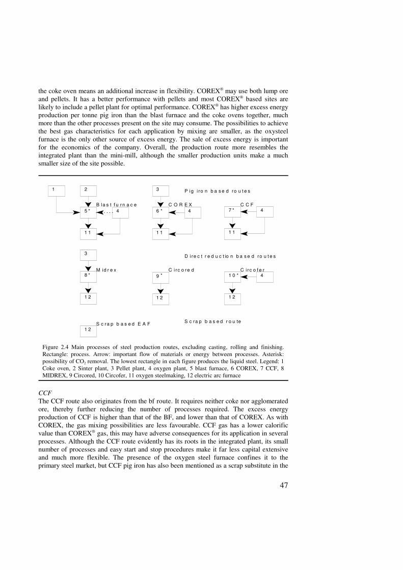
Figure 2.4 Main processes of steel production routes, excluding casting, rolling and finishing.Rectangle: process. Arrow: important flow of materials or energy between processes. Asterisk:possibility of CO2 removal. The lowest rectangle in each figure produces the liquid steel. Legend: 1Coke oven, 2 Sinter plant, 3 Pellet plant, 4 oxygen plant, 5 blast furnace, 6 COREX, 7 CCF, 8MIDREX, 9 Circored, 10 Circofer, 11 oxygen steelmaking, 12 electric arc furnace
the coke oven means an additional increase in flexibility. COREX® may use both lump oreand pellets. It has a better performance with pellets and most COREX® based sites arelikely to include a pellet plant for optimal performance. COREX® has higher excess energyproduction per tonne pig iron than the blast furnace and the coke ovens together, muchmore than the other processes present on the site may consume. The possibilities to achievethe best gas characteristics for each application by mixing are smaller, as the oxysteelfurnace is the only other source of excess energy. The sale of excess energy is importantfor the economics of the company. Overall, the production route more resembles theintegrated plant than the mini-mill, although the smaller production units make a muchsmaller size of the site possible.
CCFThe CCF route also originates from the bf route. It requires neither coke nor agglomeratedore, thereby further reducing the number of processes required. The excess energyproduction of CCF is higher than that of the BF, and lower than that of COREX. As withCOREX, the gas mixing possibilities are less favourable. CCF gas has a lower calorificvalue than COREX® gas, this may have adverse consequences for its application in severalprocesses. Although the CCF route evidently has its roots in the integrated plant, its smallnumber of processes and easy start and stop procedures make it far less capital extensiveand much more flexible. The presence of the oxygen steel furnace confines it to theprimary steel market, but CCF pig iron has also been mentioned as a scrap substitute in the
48
electric arc furnace. The small production units would allow a much smaller-scaleproduction site than that of the current integrated plant.
MIDREXThe Midrex route may be regarded as the product of an add-on to the mini-mill. Midrexmay use pure lump ore, but it functions much better with a high share of pellets. Therefore,for optimal functioning the Midrex plant requires the presence of a pellet plant. This meansthat the production route is much more capital-extensive than the mini-mill, even more thanthe conventional integrated plant. The penalty for low production is consequentially higher,robbing the route from the inexpensive flexibility of the mini-mill. Yet, the route has, as themini-mill, the possibility to produce steel from any mixture of scrap and primary materials.As with all DR-routes, this may be an important advantage if the product specificationsallow scrap shares over 45%. The Midrex route has no important excess energy sources.Neither Midrex nor the electric arc furnace produce relevant quantities of combustiblegases. The plant will have to purchase most of the gases required for rolling and finishing,as the other DR routes. The size of production sites based on the Midrex route may beclose to that of the mini-mill.
CircoredFrom the selected DR routes, the Circored® route retains most of the mini-millcharacteristics. Circored® does not require any additional pre-processing of ore or fuel, andaddition of Circored® to a mini-mill does not make the route as capital extensive as theMIDREX route. Therefore, the penalty for production stops is not excessive. The routemay produce steel from any mixture of scrap and primary materials. As in all DR-routes,there are no relevant excess energy producers.
CircoferCompared with Circored®, Circofer® requires a relatively high capacity for oxygenproduction. On the other hand, it has the advantage that it requires coal instead of naturalgas for reduction, the latter being generally rather expensive in industrialised countries. Asall DR routes, the Circofer® route contains no excess energy producers. Circofer® has acirculating gas system with CO2 removal. CO2 storage, results only in additional costs forcompression and transport of CO2.
Table 2.31 Some characteristics of the production routes. Bf and EAF sec represent the current integrated plantsand mini-mills, respectively. Processes and investments excluding casting, rolling and finishing. Betweenbrackets: Euro/tonne capacity for routes with CO2 removal.Route installation
types, no. capacity,Mt
increase unit,Mt
inflexibleinstallations
excess energysources
Euro/t capacity(CO2 removal)
Scrap ratiomin max
bf 5 >6 ~3 2 3 315 (368) 0.08 ~0.35COREX 4 >1 0.5-1 0 2 323 (402) 0.08 ~0.35ccf 3 >1 0.5-1 0 2 176 (225) 0.08 ~0.35midrex 4* >1 0.5-1 0 0 380 (399) 0 1Circored 3* >1 0.5-1 0 0 252 (273) 0 1Circofer 3 >1 0.5-1 0 0 247 (255) 0 1EAF sec 2* >0.5 0.5-1 0 0 86 0 1* On-site oxygen plant assumed; purchase of oxygen may be more attractive for smaller plants
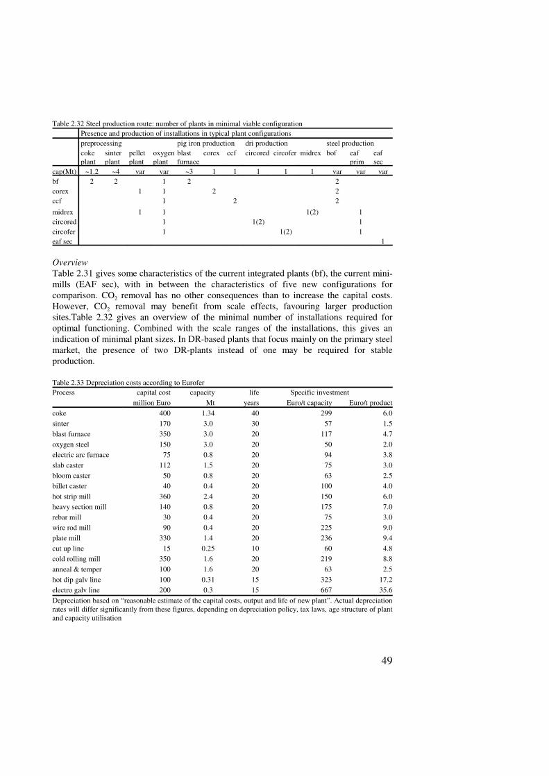
49
Table 2.32 Steel production route: number of plants in minimal viable configurationPresence and production of installations in typical plant configurationspreprocessing pig iron production dri production steel productioncokeplant
sinterplant
pelletplant
oxygenplant
blastfurnace
corex ccf circored circofer midrex bof eafprim
eafsec
cap(Mt) ~1.2 ~4 var var ~3 1 1 1 1 1 var var varbf 2 2 1 2 2corex 1 1 2 2ccf 1 2 2
midrex 1 1 1(2) 1circored 1 1(2) 1circofer 1 1(2) 1eaf sec 1
OverviewTable 2.31 gives some characteristics of the current integrated plants (bf), the current mini-mills (EAF sec), with in between the characteristics of five new configurations forcomparison. CO2 removal has no other consequences than to increase the capital costs.However, CO2 removal may benefit from scale effects, favouring larger productionsites.Table 2.32 gives an overview of the minimal number of installations required foroptimal functioning. Combined with the scale ranges of the installations, this gives anindication of minimal plant sizes. In DR-based plants that focus mainly on the primary steelmarket, the presence of two DR-plants instead of one may be required for stableproduction.
Table 2.33 Depreciation costs according to EuroferProcess capital cost capacity life Specific investment
million Euro Mt years Euro/t capacity Euro/t productcoke 400 1.34 40 299 6.0sinter 170 3.0 30 57 1.5blast furnace 350 3.0 20 117 4.7oxygen steel 150 3.0 20 50 2.0electric arc furnace 75 0.8 20 94 3.8slab caster 112 1.5 20 75 3.0bloom caster 50 0.8 20 63 2.5billet caster 40 0.4 20 100 4.0hot strip mill 360 2.4 20 150 6.0heavy section mill 140 0.8 20 175 7.0rebar mill 30 0.4 20 75 3.0wire rod mill 90 0.4 20 225 9.0plate mill 330 1.4 20 236 9.4cut up line 15 0.25 10 60 4.8cold rolling mill 350 1.6 20 219 8.8anneal & temper 100 1.6 20 63 2.5hot dip galv line 100 0.31 15 323 17.2electro galv line 200 0.3 15 667 35.6Depreciation based on “reasonable estimate of the capital costs, output and life of new plant”. Actual depreciationrates will differ significantly from these figures, depending on depreciation policy, tax laws, age structure of plantand capacity utilisation

50