Embed Size (px)
Citation preview

EE6401– ELECTRICAL MACHINCES-1
QUESTION AND ANSWERS
UNIT I MAGNETIC CIRCUITS AND MAGNETIC
1. Mention the types of electrical machines.There are three basic rotating machines types, namely
a. The dc machinesb. the poly phase synchronous machine (ac), andc. Poly and single phase induction machine (ac) and a stationary machine, namelyTransformer
2. State Ohm’s law for magnetic circuit.It states that the magneto motive force across the magnetic element is equal to the product of themagnetic flux through the magnetic element and the reluctance of the magnetic material. It isgiven by MMF = Flux X Reluctance
3. Define leakage fluxThe flux setup in the air paths around the magnetic material is known as leakage flux.
4. Define magnetic reluctanceThe opposition offered by the magnetic circuit for the magnetic flux path is known as magneticreluctance. It is analogous to electric resistance.
5. Draw the typical normal magnetization curve of ferromagnetic material.
6. What is fringing?In the air gap the magnetic flux fringes out into neighboring air paths due to the reluctance of
air gap which causes a non uniform flux density in the air gap of a machine. This effect is calledfringing effect.
SRI VIDYA COLLEGE OF ENGG & TECH, VIRUDHUNAGAR QUESTION BANK
UNIT I MAGNETIC CIRCUITS AND MAGNETIC MATERIALS Page 1 of 5

7. State stacking factor.The stacking factor is defined as the ratio of the net cross sectional area of a magnetic core to
the gross cross sectional area of the magnetic core. Due to lamination net cross sectional are willbe always less than gross cross sectional area. Therefore the value of stacking factor is alwaysless than unity.
8. Mention some magnetic materials suitable for fabrication of permanent magnets.Samarium-cobalt, Neodymium-iron-boron material.
Alnicos, chromium steels, copper–nickel alloy, nickel, cobalt, tungsten and aluminium.
9. What is magnetostriction?When ferromagnetic materials are subjected to magnetizing mmf, these may undergo smallchanges in dimension; this phenomenon is known as magnetostriction.
10. Define statically induced emf.The coil remains stationary with respect to flux, but the flux through it changes with time. Theemf induced is known as statically induced emf.Ex: Transformer
11. Define dynamically induced emf.Flux density distribution remains constant and stationary but the coil moves relative to it. Theemf induced is known as dynamically induced emf.Ex: Generator
12. State Fleming’s right hand rule.Extend the thumb, fore and middle finger of the right hand so that they are mutuallyperpendicular to each other. If the thumb represents the direction of movement of conductor andthe fore finger the direction of magnetic flux, then the middle finger represents the direction ofemf
13. State Fleming’s Left hand rule.Extend the thumb, fore and middle finger of the right hand so that they are mutuallyperpendicular to each other. If the forefinger represents the direction of flux and the middlefinger the direction of current, then the middle finger represents the direction of movement ofconductor.
14. What are the losses called as core loss?Hysteresis loss and eddy current loss.
16 What is magnetic circuit?The closed path followed by magnetic flux is called magnetic circuit
17. Define magnetic flux?The magnetic lines of force produced by a magnet is called magnetic flux it is denoted as Ф andits unit is Weber
SRI VIDYA COLLEGE OF ENGG & TECH, VIRUDHUNAGAR QUESTION BANK
UNIT I MAGNETIC CIRCUITS AND MAGNETIC MATERIALS Page 2 of 5

18. Define magnetic flux density?It is the flux per unit area at right angles to the flux it is denoted by B and unit is Weber/m2
19. Define magneto motive force?MMF is the cause for producing flux in a magnetic circuit. the amount of flux setup in the coredecent upon current(I)and number of turns(N).the product of NI is called MMF and it determinethe amount of flux setup in the magnetic circuit MMF=NI ampere turns (AT)20. What are quasi – static fields?The time invariant fields are called static fields. The quasi – static field theory is applicable atlow frequencies when the dimensions of the region of interest are small compared to thewavelength of the electromagnetic field that permeates it.The field which is slowly varying i.e the time required by electromagnetic field wave needs topropagate through a typical dimension of the system of interest is small compared with the timescale of field evolution of the system then the field is called quasi – static field.
21. A coil is wound on an iron core to form a solenoid. A certain current is passed through thecoil which is producing a flux of 40 µWb. The length of magnetic circuit is 75cm while its crosssectional area is 3 cm2. Calculate the energy stored in the circuit. Assume relative permeabilityof iron as 1500.
22. A coil carries 200 turns gives raise a flux of 500 µWb when carrying a certain current. If thiscurrent is reversed in 1/10 th of a second. Find the average e.m.f. induced in the coil.
23. A conductor of 2 m length moves with a uniform velocity of 1.27 m/sec under a magneticfield having a flux density of 1.2 Wb/m2 (tesla). Calculate the magnitude of induced e.m.f. ifconductor moves.
Part – B1. In a rectangular electromagnetic relay, the exciting coil has 1200 turns.Cross sectional area ofthe core is A = 6 cm × 6 cm. neglect the reluctance of the magnetic circuit and fringing effects.With coil current kept constant at 2A, derive expression for force on armature as a function of airgap of length x. Find the work done by the magnetic field when x decreases from 1 cm to 0.5 cmby integrating the force.
2. Compare statically induced emf and dynamically induced emf.
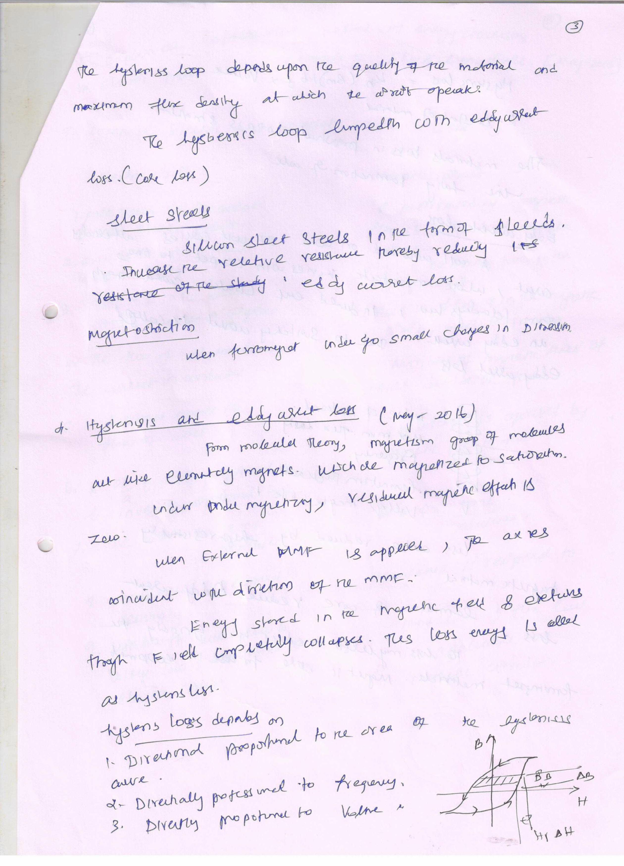
3. Discuss the origin of hysteresis and eddy current losses in electrical machines. Also suggestthe methods in construction to minimize the above losses.
4. A straight conductor of 2 m length carries a current of 20A. It is lying at right angles to auniform magnetic flux density of 0.8 T. Find: (1) the force developed on the conductor (2) thepower required to drive the conductor at a uniform speed of 25 m/s and (3) the emf induced inthe conductor.
5. Explain the AC operation of magnetic circuit in electrical machines.
6. For a magnetic circuit, find the followinga) Induced emf ‘e’ for Bc = 1.2 sin 314 tT
SRI VIDYA COLLEGE OF ENGG & TECH, VIRUDHUNAGAR QUESTION BANK
UNIT I MAGNETIC CIRCUITS AND MAGNETIC MATERIALS Page 3 of 5

b) Reluctance Rc and Rg with current 1.06 Ac) Coil inductance Ld) Magnetic field energy at Bc = 1.2T given Ac = 16 x104 m
7. Derive Torque equation of a D.C. Machine
8. Derive Faraday’s Laws of Electromagnetic Induction?
9. 15. A 50 KVA, 4400/220 V, transformer has R1 = 3.45 Ω; R2 = 0.009 Ω. The values ofreactances are X1 = 5.2 Ω and X2 = 0.015 Ω. Calculate for the transformer.(i) Equivalent resistance referred to primary(ii) Equivalent reactance reference to primary(iii) Equivalent impedance reference to primary(iv) Equivalent resistance, reactance and impedance referred to secondary. It is the measure ofmmf which, when applied to the magnetic circuit would reduce its flux density to zero, i.e., itdemagnetizes the magnetic circuit.
10. Derive an expression for an energy density in magnetic circuits.
11. Explain the methods of energy conversion via Electric field, with examples of ElectricalMachines.
12. State properties of magnetic material for fabrication Permanent Magnet and Electromagnet.
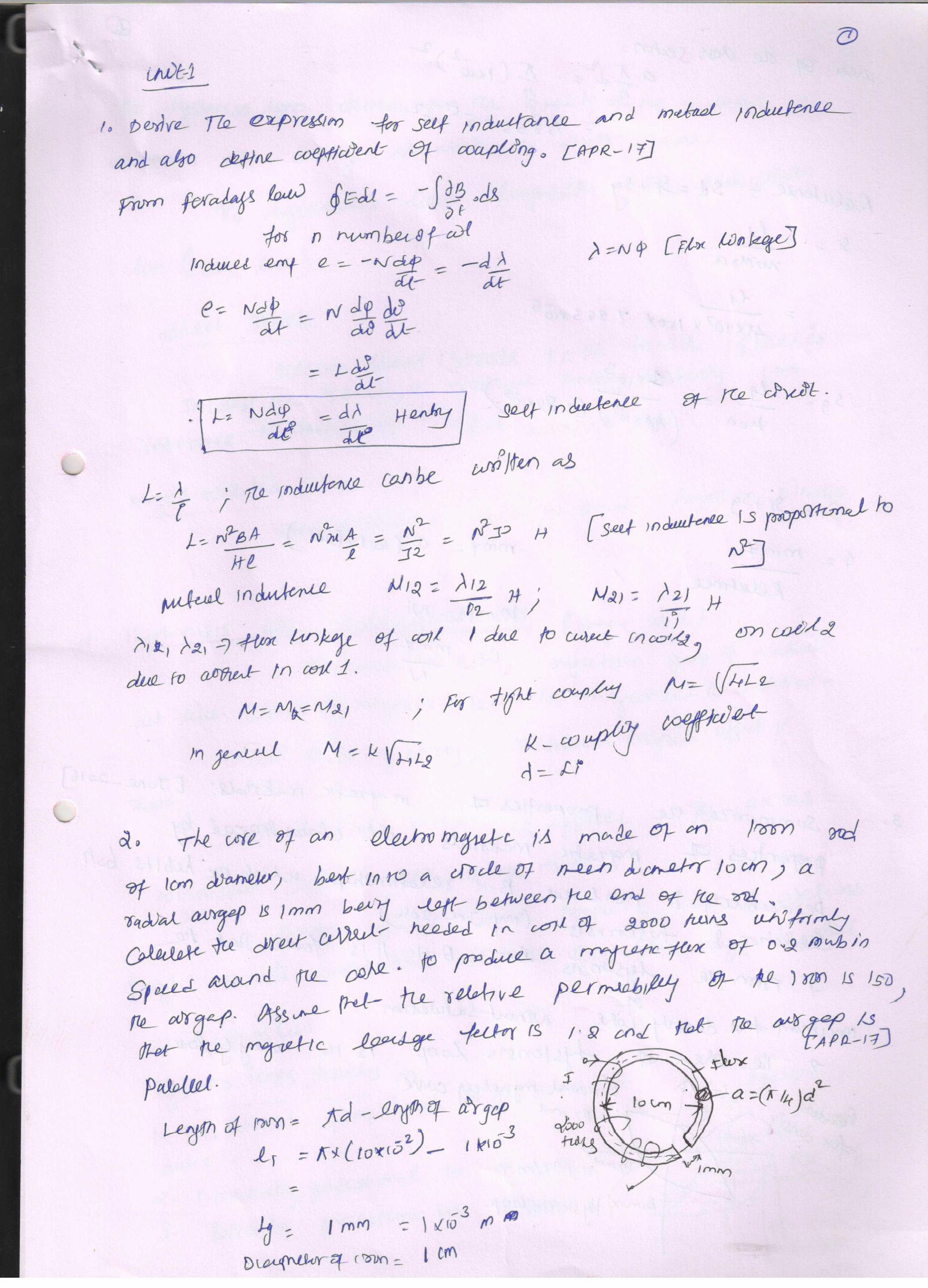
13. Derive the expression for self and mutual inductance of the coil.
14. Explain the power losses that occur in a magnetic material when it undergoes cyclicmagnetization.
15. Discuss in detail the magnetic circuits and the electrical analog of magnetic circuits.
16. Compare electric and magnetic circuit by their similarities and dissimilarities.
17. Discuss in detail the following:
(i) B-H relationship (ii) Leakage flux (iii) Fringing (iv) Stacking factor
SRI VIDYA COLLEGE OF ENGG & TECH, VIRUDHUNAGAR QUESTION BANK
UNIT I MAGNETIC CIRCUITS AND MAGNETIC MATERIALS Page 4 of 5

SRI VIDYA COLLEGE OF ENGG & TECH, VIRUDHUNAGAR QUESTION BANK
UNIT I MAGNETIC CIRCUITS AND MAGNETIC MATERIALS Page 5 of 5