Embed Size (px)
Citation preview
Name: _____________________________________________ Date: _________________ Class: _________________
Electronic Circuit WorksheetUsing systems of equations and Ohm’s law to solve a circuit problem.
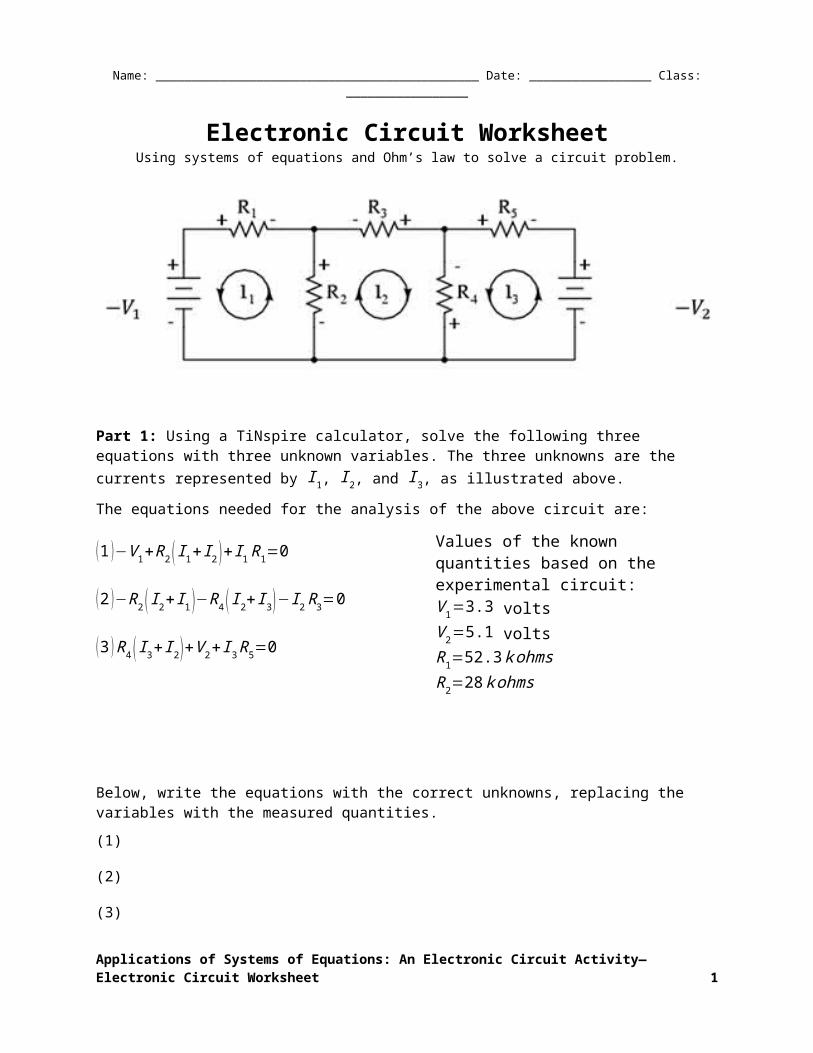
Part 1: Using a TiNspire calculator, solve the following three equations with three unknown variables. The three unknowns are the currents represented by I 1, I 2, and I 3, as illustrated above.
The equations needed for the analysis of the above circuit are:
(1 )−V 1+R2 ( I 1+ I 2 )+ I 1 R1=0
(2 )−R2 ( I 2+ I1 )−R4 ( I 2+ I 3 )−I 2 R3=0
(3 ) R4 ( I 3+ I2 )+V 2+ I 3 R5=0
Below, write the equations with the correct unknowns, replacing the variables with the measured quantities.
(1)
(2)
(3)
Solve the equations using any method you choose; write your answers below. The final units are amperes.
I 1=¿
I 2=¿
I 3=¿
Applications of Systems of Equations: An Electronic Circuit Activity—Electronic Circuit Worksheet 1
Values of the known quantities based on the experimental circuit:V 1=3.3 voltsV 2=5.1 voltsR1=52.3 k ohmsR2=28 k ohmsR3=10.5 k ohmsR4=12.1 k ohmsR5=14.7 k ohms
Name: _____________________________________________ Date: _________________ Class: _________________
Applications of Systems of Equations: An Electronic Circuit Activity—Electronic Circuit Worksheet 2
Name: _____________________________________________ Date: _________________ Class: _________________
Part 2: Now that you know the current values, let’s check them by doing an experiment.
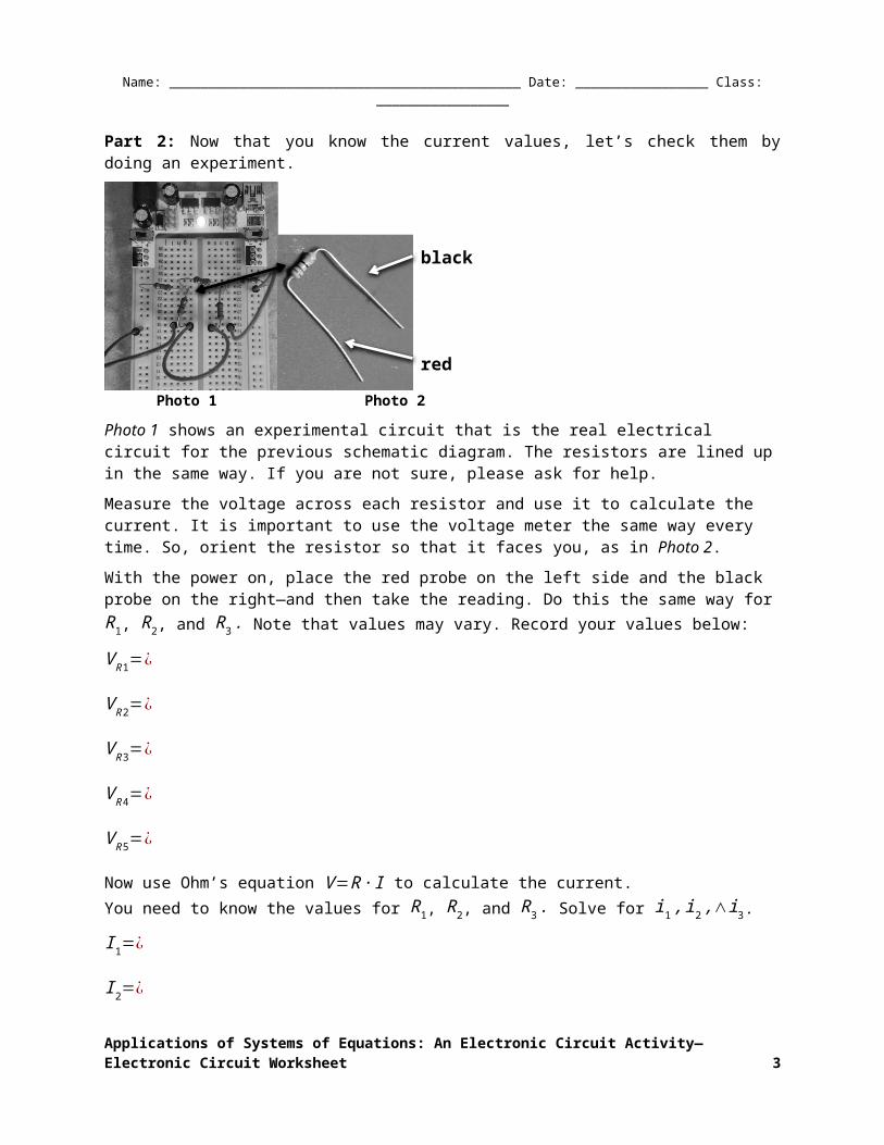
Photo 1 Photo 2
Photo 1 shows an experimental circuit that is the real electrical circuit for the previous schematic diagram. The resistors are lined up in the same way. If you are not sure, please ask for help.
Measure the voltage across each resistor and use it to calculate the current. It is important to use the voltage meter the same way every time. So, orient the resistor so that it faces you, as in Photo 2.
With the power on, place the red probe on the left side and the black probe on the right—and then take the reading. Do this the same way for R1, R2, and R3 . Note that values may vary. Record your values below:
V R1=¿
V R2=¿
V R 3=¿
V R4=¿
V R 5=¿
Now use Ohm’s equation V=R ∙ I to calculate the current. You need to know the values for R1, R2, and R3 . Solve for i1 , i2 ,∧i3.
I 1=¿
I 2=¿
I 3=¿
Part 3: How close were your current values using both methods? Use percentage difference in your explanation.
Applications of Systems of Equations: An Electronic Circuit Activity—Electronic Circuit Worksheet 3
black probe
red probe