Embed Size (px)
Citation preview
INSTALLATION MANUAL 2-Post
ALM-2524 ALM-2524/1Ph ALM-3024
ISSUED 02-11-1999
Autec Hefbruggen bv
Industrieterrein Ijsselveld, Vlasakker 11, 3417 XT MONTFOORT, The Netherlands Tel:+31(0) 348- 477000 Fax:+31 (0)348 -475104 E-mail: [email protected]
`
2-Post lifts - electrical mechanical with baseframe
CONTENTS PAG 1 Introduction 02 2 Packing, transport, storage 02
en-TD-ALM-2524-01
INSTALLATION MANUAL 2-Post
ALM-2524 ALM-2524/1Ph ALM-3024
ISSUED 02-11-1999
Autec Hefbruggen bv
Industrieterrein Ijsselveld, Vlasakker 11, 3417 XT MONTFOORT, The Netherlands Tel:+31(0) 348- 477000 Fax:+31 (0)348 -475104 E-mail: [email protected]
3 Safety definition 02 4 Description of the lift 02 5 Installation 03 5.1 Mod. bearing safety nut 04 6 Connection to power supply 09 7 Safety check 09 8 Installation report 09 9 Electrical scheme 10
1. INTRODUCTION
This manual is made exclu-sively for installation personnel. Read this manual carefully before installation. 2. PACKING, TRANSPORT
AND STORAGE
All packing, lifting, handling, transport and unpacking operations are to perform exclusively by expert personnel with knowledge of the lift and the contents of this manual. LIFTING AND HANDLING The wooden crates may be lifted and moved with a lift truck (Fig.1) crane or bridge crane.
Fig.1 The equipment chosen must be suitable for safe lifting and moving, bearing in mind the dimensions, weight, centre of gravity, any protruding or fragile parts.
STORAGE Packed machinery must always be kept in a covered, protected place, at a temperature between -10°C and +40°C, and must not be exposed to direct sunlight. OPENING THE CRATES When the crates arrive, check that the machine has not been damaged during transport and that all parts listed are present. DISPOSAL OF CRATES The wood of the crates may be re-used or recycled
Carefully reading of the safety instruction is strongly rec-ommended.
3. SAFETY DEFINITION The manufacturer disclaims all liability for injure to persons or damage to vehicles and other property caused by incorrect and unauthorised use of the lift. In order to understand the terminol-ogy used in this manual, the operator must have specific experience in work-shop, service, maintenance and repair activities, the ability to interpret correctly the drawings and descriptions contained in the manual and be acquainted with the general and specific safety rules relevant to the country in which the machine has been installed. The same applies to the maintenance fitter, who must also posses specific and special-ised knowledge (mechanical, engineer-ing) needed to perform the operations described in the manual in complete safety. The words “operator” and “main-tenance fitter” used in this manual are construed as follows: OPERATOR: person authorised to use the lift. The minimum legal age of the operator is 18 years. MAINTENANCE FITTER: person authorised for routine maintenance of the lift.
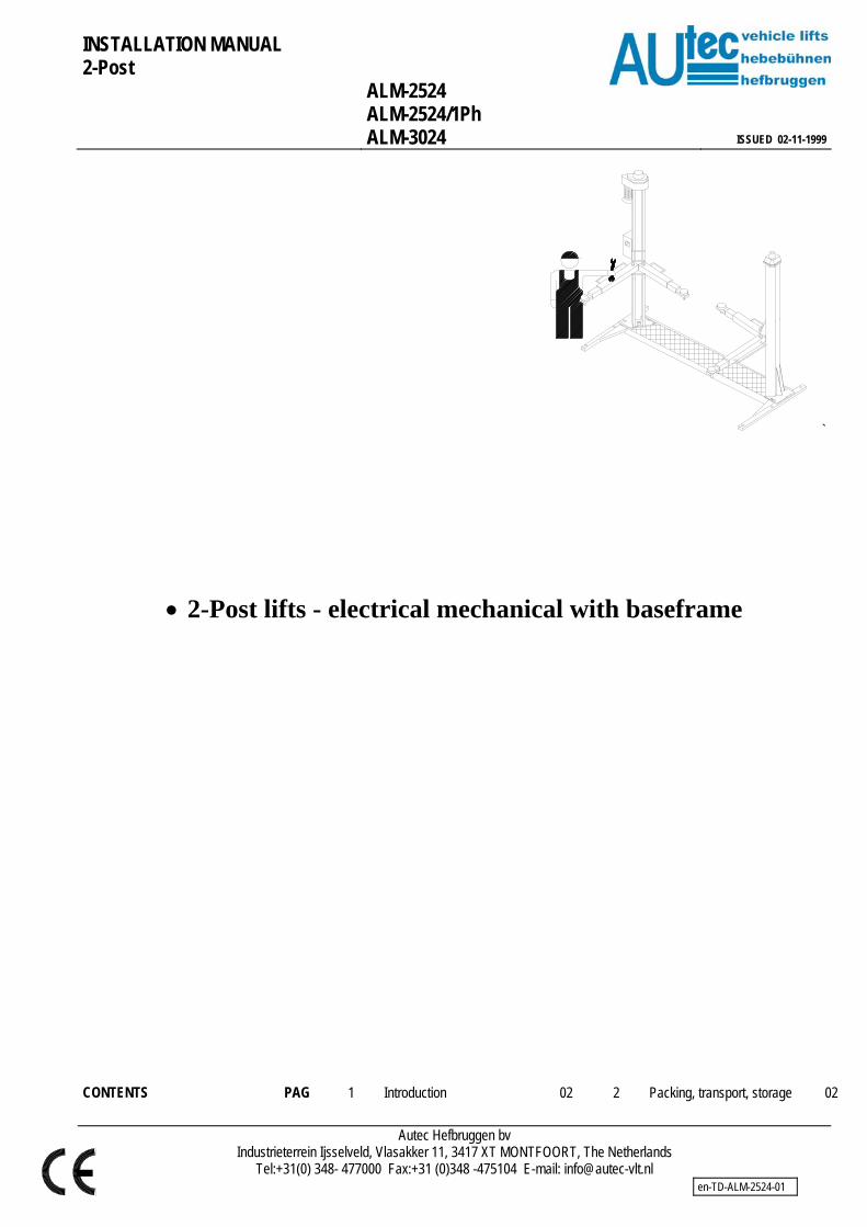
4. DESCRIPTION OF THE LIFT (Fig.2)
The lift mainly comprises: Base (1), in 3 parts. Two base cover plates (5) in chequered steel are fixed to the upper part of the base. A roller chain 2) is located inside the base to transmit drive from the motorpost(3) to the ser-vicepost (4). Each post houses the mobile units for lifting the vehicle.
Fig.2 CARRIAGES (Fig.3) The welded steel carriage (1) connected in the lower part to the lifting arms by flanges and pins. The carriage is con-nected at the centre to the lead nut (2), which provides lifting motion by travel-ling on the lead screws. The carriage is laterally joined by pins to the sliding shoes(6), which keep it on the slide way. Two telescoping arms, one long (3) and one short (4) each with a height adjustable disk support plate (5) at one end for picking up the vehicle, and a hole at the other and for connection to the carriage.
Fig.3 TRANSMISSION (Fig.4) The unit comprises two special-steel helical screws (2) suspended in the upper part of the post by an axial bear-ing (6) and a thrust bearing (7). The lead screw in the drive post is operated by a system comprising an electric motor (8), pulleys (9) and V-belts (10)
en-TD-ALM-2524-02
INSTALLATION MANUAL 2-Post
ALM-2524 ALM-2524/1Ph ALM-3024
ISSUED 02-11-1999
Autec Hefbruggen bv
Industrieterrein Ijsselveld, Vlasakker 11, 3417 XT MONTFOORT, The Netherlands Tel:+31(0) 348- 477000 Fax:+31 (0)348 -475104 E-mail: [email protected]
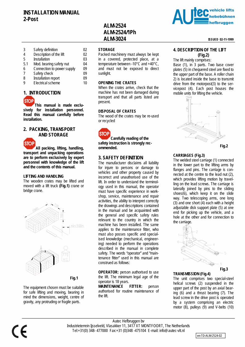
which transmit drive to the other lead screw by means of a chain and chain sprocket transmission inside the base.
Fig.4 CONTROL PANEL (Fig.5) The electric control panel includes: Master switch (11) “Lift” button (12) “Descend” button(13)
Fig.5 5. INSTALLATION
The following operation must be performed by qualified personnel only.
INSTALLATION REQUISITE CHECK-LIST The lift is designed for installation in enclosed areas suitably protected from the weather. The place of installation must be clear of areas where there is a risk of potentially explosive atmosphere CONNECTION TO POWER SUPPLY The customer is responsible for an electrical system at the installation site which is equipped with the protective devices envisaged by national safety standards.
ATTENTION If the electrical system is not conform the recommended standards (p.9). The mechanic will only test the lift with a “emergency” electric cable, which is replaced after testing. After testing the customer is responsible for further electrical installation by an authorised person and all extra costs. The lift must be installed in observance of the clearances between other objects (fig.6). And in compliance with any legislative requirements in the country of installation. Check in particular: minimum height 5000mm, inclusive
height of vehicle and maximum height of arms, ( 2000 mm).
minimum distance from walls: 500 mm.
minimum working area: 500 mm. area for COMMAND STATION. area for maintenance, access and
emergency escape routes. position in relation to other ma-
chines. proximity to power supply for trou-
ble-free hook-up.
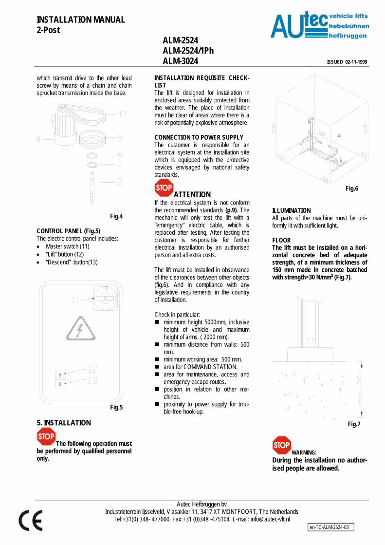
Fig.6 ILLUMINATION All parts of the machine must be uni-formly lit with sufficient light. FLOOR The lift must be installed on a hori-zontal concrete bed of adequate strength, of a minimum thickness of 150 mm made in concrete batched with strength>30 N/mm² (Fig.7).
Fig.7
WARNING: During the installation no author-ised people are allowed.
en-TD-ALM-2524-03
INSTALLATION MANUAL 2-Post
ALM-2524 ALM-2524/1Ph ALM-3024
ISSUED 02-11-1999
Autec Hefbruggen bv
Industrieterrein Ijsselveld, Vlasakker 11, 3417 XT MONTFOORT, The Netherlands Tel:+31(0) 348- 477000 Fax:+31 (0)348 -475104 E-mail: [email protected]
INSTALLATION 1. Construct the base frame from the
centre part and the two end pieces. Watch out: The holes in the mid-dlepart of the base frame must be on the side with the long arms (Fig.8).
Fig.8 2. Fit the chain guides using the
screws (Fig.9).
Fig.9 3. Position the base frame in the in-
stallation area. 4. Lay the chain in the guides and
connect the ends with the split link. ATTENTION: The split link lock must be placed at the upper-side of the chain.
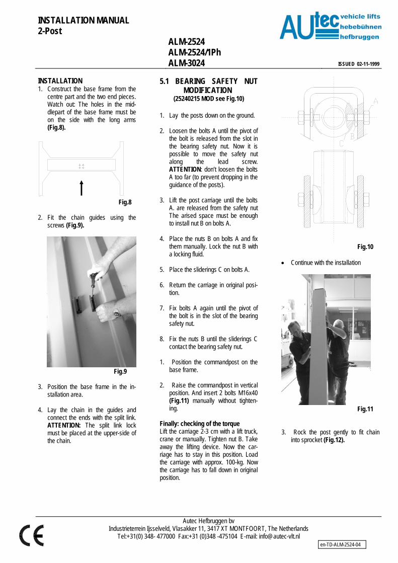
5.1 BEARING SAFETY NUT MODIFICATION
(25240215 MOD see Fig.10)
1. Lay the posts down on the ground. 2. Loosen the bolts A until the pivot of
the bolt is released from the slot in the bearing safety nut. Now it is possible to move the safety nut along the lead screw. ATTENTION: don’t loosen the bolts A too far (to prevent dropping in the guidance of the posts).
3. Lift the post carriage until the bolts
A. are released from the safety nut The arised space must be enough to install nut B on bolts A.
4. Place the nuts B on bolts A and fix
them manually. Lock the nut B with a locking fluid.
5. Place the sliderings C on bolts A. 6. Return the carriage in original posi-
tion. 7. Fix bolts A again until the pivot of
the bolt is in the slot of the bearing safety nut.
8. Fix the nuts B until the sliderings C
contact the bearing safety nut. 1. Position the commandpost on the
base frame. 2. Raise the commandpost in vertical
position. And insert 2 bolts M16x40 (Fig.11) manually without tighten-ing.
Finally: checking of the torque Lift the carriage 2-3 cm with a lift truck, crane or manually. Tighten nut B. Take away the lifting device. Now the car-riage has to stay in this position. Load the carriage with approx. 100-kg. Now the carriage has to fall down in original position.
Fig.10 Continue with the installation
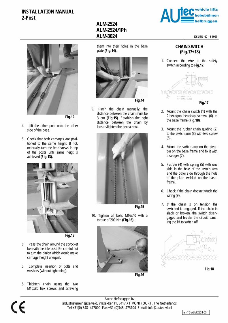
Fig.11 3. Rock the post gently to fit chain
into sprocket (Fig.12).
en-TD-ALM-2524-04
INSTALLATION MANUAL 2-Post
ALM-2524 ALM-2524/1Ph ALM-3024
ISSUED 02-11-1999
Autec Hefbruggen bv
Industrieterrein Ijsselveld, Vlasakker 11, 3417 XT MONTFOORT, The Netherlands Tel:+31(0) 348- 477000 Fax:+31 (0)348 -475104 E-mail: [email protected]
Fig.12
4. Lift the other post onto the other side of the base.
5. Check that both carriages are posi-
tioned to the same height. If not, manually turn the lead srews in top of the posts until same heigt is achieved (Fig.13).
Fig.13 6. Pass the chain around the sprocket
beneath the idle post. Be careful not to turn the pinion which would make carriage height unequal.
5. Complete insertion of bolts and
washers (without tightening). 8. Thighten chain using the two
M10x80 hex screws and screwing
them into their holes in the base plate (Fig.14).
Fig.14
9. Pinch the chain manually, the distance between the chain must be 3 cm (Fig.15). Establish the right distance between the chain by loosen/tighten the hex screws.
Fig.15 10. Tighten all bolts M16x40 with a
torque of 200 Nm (Fig.16).
Fig.16
CHAIN SWITCH (Fig.17+18)
1. Connect the wire to the safety
switch according to Fig.17.
Fig.17 2. Mount the chain switch (1) with the
2-hexagon headcap screws (6) to the base frame (Fig.18).
3. Mount the rubber chain guiding (2)
to the switch arm (3) with two-screw (8).
4. Mount the switch arm on the pivot-
pin on the base frame and fix it with a seeger (7).
5. Put pin (4) with spring (5) with one
side in the hole of the switch arm and the other side through the hole of the plate welded on the base-frame.
6. Check if the chain doesn’t touch the
wiring (9). 7. If the chain is on tension the
switched is engaged. If the chain is slack or broken, the switch disen-gages and breaks the circuit, caus-ing the lift to switch off.
Fig.18
en-TD-ALM-2524-05
INSTALLATION MANUAL 2-Post
ALM-2524 ALM-2524/1Ph ALM-3024
ISSUED 02-11-1999
Autec Hefbruggen bv
Industrieterrein Ijsselveld, Vlasakker 11, 3417 XT MONTFOORT, The Netherlands Tel:+31(0) 348- 477000 Fax:+31 (0)348 -475104 E-mail: [email protected]
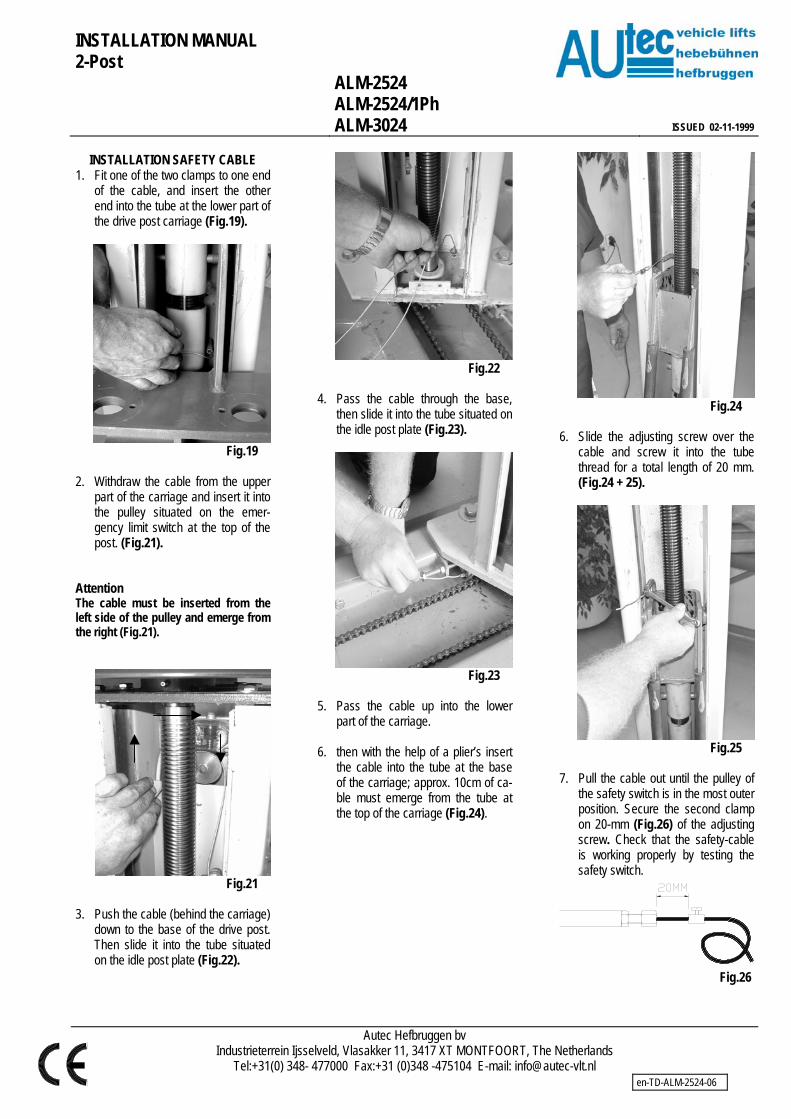
INSTALLATION SAFETY CABLE 1. Fit one of the two clamps to one end
of the cable, and insert the other end into the tube at the lower part of the drive post carriage (Fig.19).
Fig.19 2. Withdraw the cable from the upper
part of the carriage and insert it into the pulley situated on the emer-gency limit switch at the top of the post. (Fig.21).
Attention The cable must be inserted from the left side of the pulley and emerge from the right (Fig.21).
Fig.21 3. Push the cable (behind the carriage)
down to the base of the drive post. Then slide it into the tube situated on the idle post plate (Fig.22).
Fig.22 4. Pass the cable through the base,
then slide it into the tube situated on the idle post plate (Fig.23).
Fig.23 5. Pass the cable up into the lower
part of the carriage. 6. then with the help of a plier’s insert
the cable into the tube at the base of the carriage; approx. 10cm of ca-ble must emerge from the tube at the top of the carriage (Fig.24).
Fig.24 6. Slide the adjusting screw over the
cable and screw it into the tube thread for a total length of 20 mm. (Fig.24 + 25).
Fig.25 7. Pull the cable out until the pulley of
the safety switch is in the most outer position. Secure the second clamp on 20-mm (Fig.26) of the adjusting screw. Check that the safety-cable is working properly by testing the safety switch.
Fig.26
en-TD-ALM-2524-06
INSTALLATION MANUAL 2-Post
ALM-2524 ALM-2524/1Ph ALM-3024
ISSUED 02-11-1999
Autec Hefbruggen bv
Industrieterrein Ijsselveld, Vlasakker 11, 3417 XT MONTFOORT, The Netherlands Tel:+31(0) 348- 477000 Fax:+31 (0)348 -475104 E-mail: [email protected]
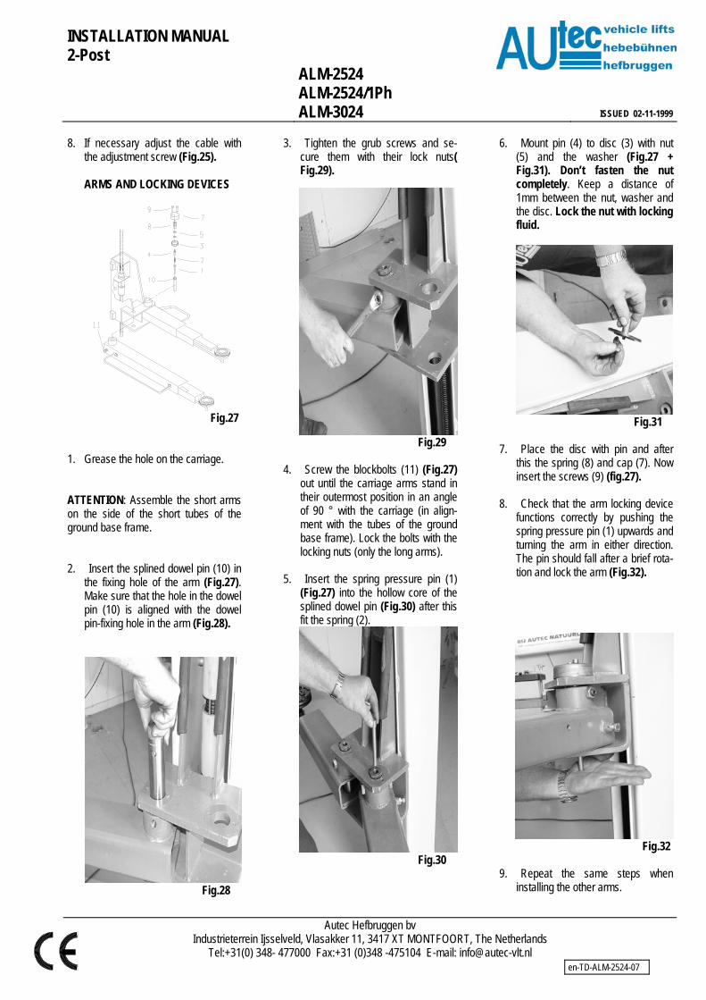
8. If necessary adjust the cable with the adjustment screw (Fig.25).
ARMS AND LOCKING DEVICES
Fig.27 1. Grease the hole on the carriage. ATTENTION: Assemble the short arms on the side of the short tubes of the ground base frame. 2. Insert the splined dowel pin (10) in
the fixing hole of the arm (Fig.27). Make sure that the hole in the dowel pin (10) is aligned with the dowel pin-fixing hole in the arm (Fig.28).
Fig.28
3. Tighten the grub screws and se-cure them with their lock nuts( Fig.29).
Fig.29 4. Screw the blockbolts (11) (Fig.27)
out until the carriage arms stand in their outermost position in an angle of 90 ° with the carriage (in align-ment with the tubes of the ground base frame). Lock the bolts with the locking nuts (only the long arms).
5. Insert the spring pressure pin (1)
(Fig.27) into the hollow core of the splined dowel pin (Fig.30) after this fit the spring (2).
Fig.30
6. Mount pin (4) to disc (3) with nut (5) and the washer (Fig.27 + Fig.31). Don’t fasten the nut completely. Keep a distance of 1mm between the nut, washer and the disc. Lock the nut with locking fluid.
Fig.31 7. Place the disc with pin and after
this the spring (8) and cap (7). Now insert the screws (9) (fig.27).
8. Check that the arm locking device
functions correctly by pushing the spring pressure pin (1) upwards and turning the arm in either direction. The pin should fall after a brief rota-tion and lock the arm (Fig.32).
Fig.32
9. Repeat the same steps when
installing the other arms.
en-TD-ALM-2524-07
INSTALLATION MANUAL 2-Post
ALM-2524 ALM-2524/1Ph ALM-3024
ISSUED 02-11-1999
Autec Hefbruggen bv
Industrieterrein Ijsselveld, Vlasakker 11, 3417 XT MONTFOORT, The Netherlands Tel:+31(0) 348- 477000 Fax:+31 (0)348 -475104 E-mail: [email protected]
10. In the lowest position the arms
should be able to swing because the pins (1) are inserted on the base (Fig.27).
FOOT GUARDS (Fig.33) Fit the foot guards (1 and 2,) to the
arms with the screws (3)
Fig.33 The long arm in their max. position,
should not touch the base frame in lowest position of the carriage.
Screw the disk support plates (6)
into the end of the arms, then se-cure with circlips (7).
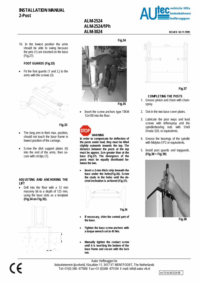
ADJUSTING AND ANCHORING THE LIFT Drill into the floor with a 12 mm
masonry bit to a depth of 125 mm, using the base slots as a template (Fig.34 en Fig.35).
Fig.34
Fig.35 Insert the screw anchors type TIKM
12x100 into the floor.
WARNING In order to compensate for deflection of the posts under load, they must be tilted slightly outwards towards the top. The distance between the posts at the top must be approx. 2cm greater than at the base (Fig.37). The divergence of the posts must be equally distributed be-tween the two. Insert a 2-mm thick strip beneath the
base under the holes(Fig.36). Screw the studs in the holes until the de-sired inclination is achieved (Fig.37).
Fig.36
If necessary, shim the central part of
the base. Tighten the base screw anchors with
a torque wrench set to 45 Nm. Manually tighten the contact screw
until it is touching the bottom of the base frame and secure with the lock nut.
Fig.37
COMPLETING THE POSTS 1. Grease pinion and chain with chain-
spray. 2. Slot in the two base cover plates. 3. Lubricate the post ways and lead
screws with teflonspray and the spindle/bearing nuts with Shell Omala 320, or equivalents.
4. Grease the bearings of the spindle
with Molytex EP2 or equivalents. 5. Install post guards and topguards.
(Fig.38 + Fig 39)
Fig.38
en-TD-ALM-2524-08
INSTALLATION MANUAL 2-Post
ALM-2524 ALM-2524/1Ph ALM-3024
ISSUED 02-11-1999
Autec Hefbruggen bv
Industrieterrein Ijsselveld, Vlasakker 11, 3417 XT MONTFOORT, The Netherlands Tel:+31(0) 348- 477000 Fax:+31 (0)348 -475104 E-mail: [email protected]
Fig.39
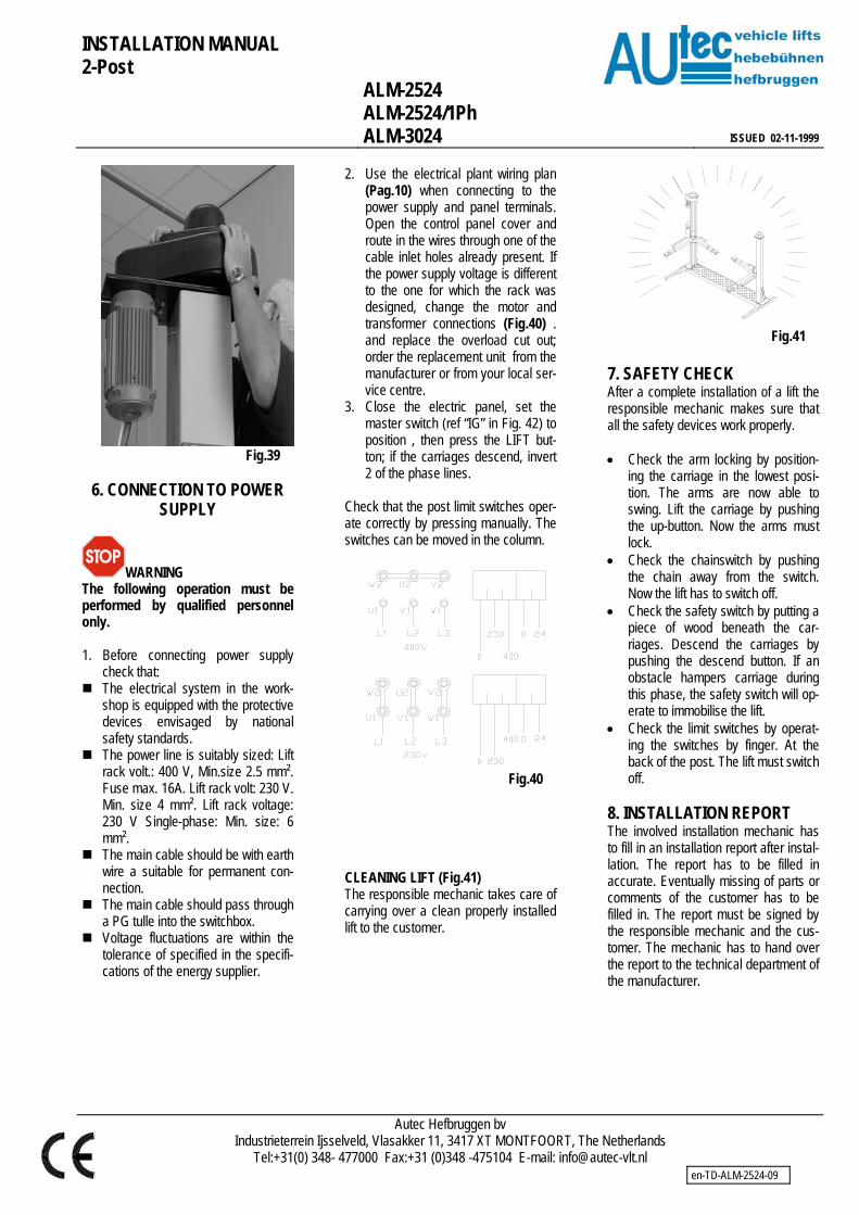
6. CONNECTION TO POWER SUPPLY
WARNING The following operation must be performed by qualified personnel only. 1. Before connecting power supply
check that: The electrical system in the work-
shop is equipped with the protective devices envisaged by national safety standards.
The power line is suitably sized: Lift rack volt.: 400 V, Min.size 2.5 mm². Fuse max. 16A. Lift rack volt: 230 V. Min. size 4 mm². Lift rack voltage: 230 V Single-phase: Min. size: 6 mm².
The main cable should be with earth wire a suitable for permanent con-nection.
The main cable should pass through a PG tulle into the switchbox.
Voltage fluctuations are within the tolerance of specified in the specifi-cations of the energy supplier.
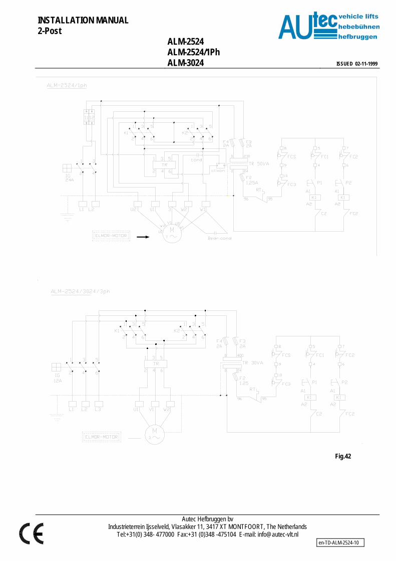
2. Use the electrical plant wiring plan (Pag.10) when connecting to the power supply and panel terminals. Open the control panel cover and route in the wires through one of the cable inlet holes already present. If the power supply voltage is different to the one for which the rack was designed, change the motor and transformer connections (Fig.40) . and replace the overload cut out; order the replacement unit from the manufacturer or from your local ser-vice centre.
3. Close the electric panel, set the master switch (ref “IG” in Fig. 42) to position , then press the LIFT but-ton; if the carriages descend, invert 2 of the phase lines.
Check that the post limit switches oper-ate correctly by pressing manually. The switches can be moved in the column.
Fig.40 CLEANING LIFT (Fig.41) The responsible mechanic takes care of carrying over a clean properly installed lift to the customer.
Fig.41 7. SAFETY CHECK After a complete installation of a lift the responsible mechanic makes sure that all the safety devices work properly. Check the arm locking by position-
ing the carriage in the lowest posi-tion. The arms are now able to swing. Lift the carriage by pushing the up-button. Now the arms must lock.
Check the chainswitch by pushing the chain away from the switch. Now the lift has to switch off.
Check the safety switch by putting a piece of wood beneath the car-riages. Descend the carriages by pushing the descend button. If an obstacle hampers carriage during this phase, the safety switch will op-erate to immobilise the lift.
Check the limit switches by operat-ing the switches by finger. At the back of the post. The lift must switch off.
8. INSTALLATION REPORT The involved installation mechanic has to fill in an installation report after instal-lation. The report has to be filled in accurate. Eventually missing of parts or comments of the customer has to be filled in. The report must be signed by the responsible mechanic and the cus-tomer. The mechanic has to hand over the report to the technical department of the manufacturer.
en-TD-ALM-2524-09
INSTALLATION MANUAL 2-Post
ALM-2524 ALM-2524/1Ph ALM-3024
ISSUED 02-11-1999
Autec Hefbruggen bv
Industrieterrein Ijsselveld, Vlasakker 11, 3417 XT MONTFOORT, The Netherlands Tel:+31(0) 348- 477000 Fax:+31 (0)348 -475104 E-mail: [email protected]
Fig.42
en-TD-ALM-2524-10