Embed Size (px)
Citation preview
2nd ADVANCED COURSE ON DIAGNOSTICS AND DATA ACQUISITION
Instrumentation Buses,Digital Communication and Protocols
J. Sousa
Summary
• Digital Communication• Signalling, Encoding and Protocols• Instrumentations Buses• Networks for Control and Data Acquisition
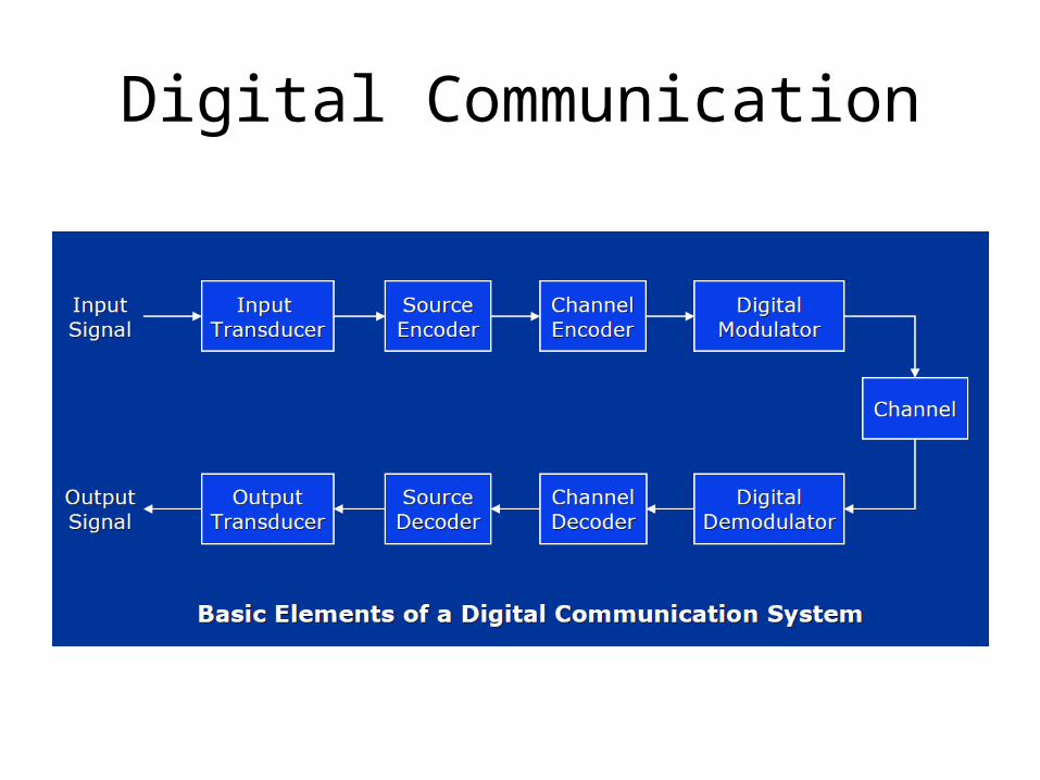
Digital Communication
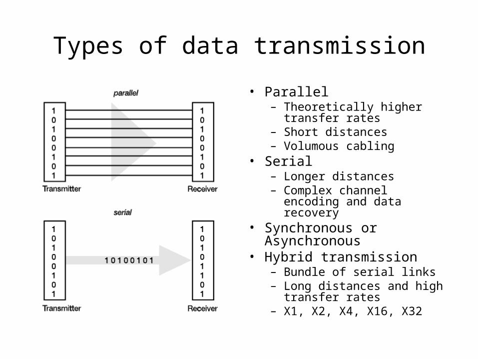
Types of data transmission
• Parallel– Theoretically higher transfer
rates– Short distances– Volumous cabling
• Serial– Longer distances– Complex channel encoding and
data recovery• Synchronous or Asynchronous• Hybrid transmission
– Bundle of serial links– Long distances and high
transfer rates– X1, X2, X4, X16, X32
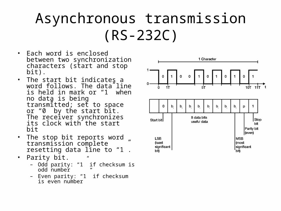
Asynchronous transmission (RS-232C)
• Each word is enclosed between two synchronization characters (start and stop bit).
• The start bit indicates a word follows. The data line is held in mark or “1” when no data is being transmitted; set to space or “0” by the start bit. The receiver synchronizes its clock with the start bit
• The stop bit reports word transmission complete resetting data line to “1”.
• Parity bit.– Odd parity: “1” if checksum is odd
number– Even parity: “1” if checksum is even
number
Synchronous transmission• Parallel or serial transmission• No start and stop bits• A continual stream of data is then sent between the two nodes• A timing signal (character) is generated periodically by the transmitter.• Receiver clock is re-synchronized by the timing signal.• Synchronous clocks in both transmitter and receiver allow data recovery.• Error detection and correction
Signal distorsion on transmission channel
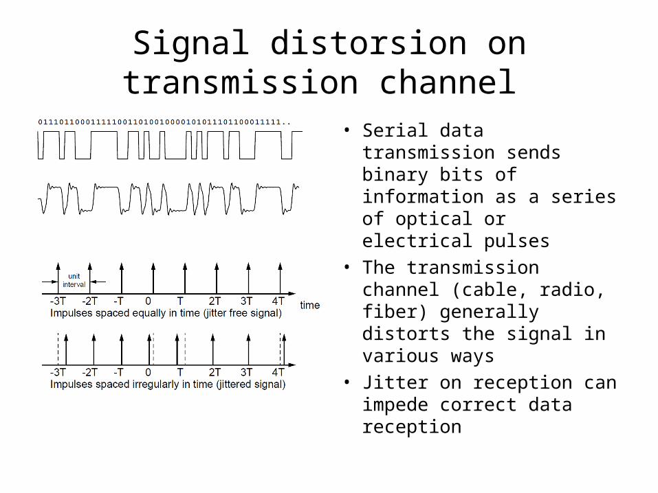
• Serial data transmission sends binary bits of information as a series of optical or electrical pulses
• The transmission channel (cable, radio, fiber) generally distorts the signal in various ways
• Jitter on reception can impede correct data reception
Source encoding – 8b/10b
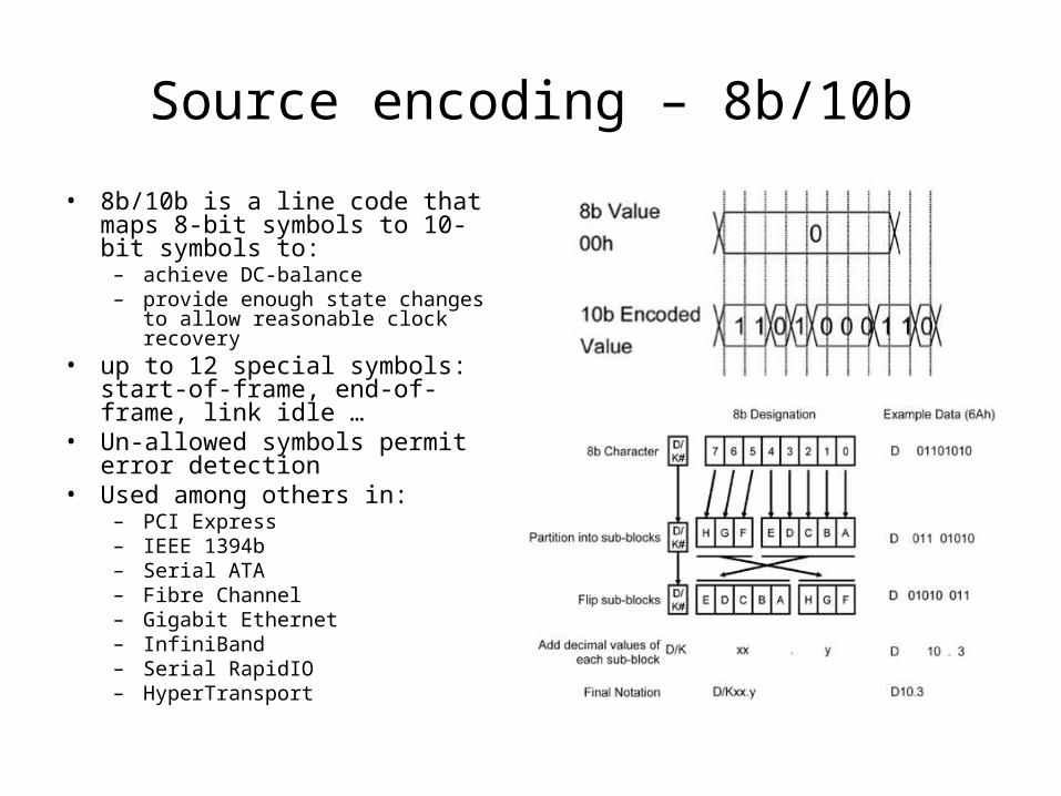
• 8b/10b is a line code that maps 8-bit symbols to 10-bit symbols to:– achieve DC-balance– provide enough state changes to allow
reasonable clock recovery• up to 12 special symbols: start-of-
frame, end-of-frame, link idle …• Un-allowed symbols permit error
detection• Used among others in:
– PCI Express– IEEE 1394b– Serial ATA– Fibre Channel– Gigabit Ethernet– InfiniBand– Serial RapidIO– HyperTransport
Communication Protocols
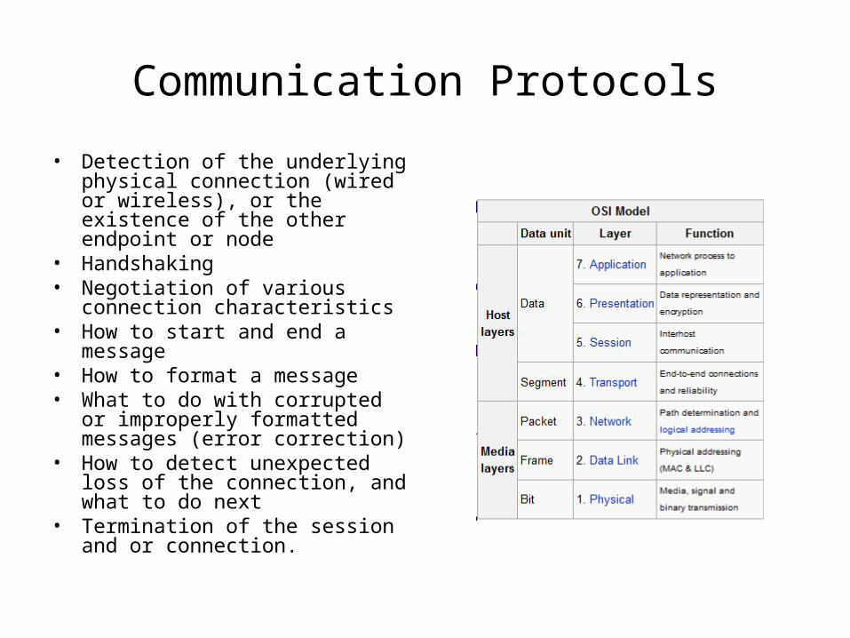
• Detection of the underlying physical connection (wired or wireless), or the existence of the other endpoint or node
• Handshaking• Negotiation of various connection
characteristics• How to start and end a message• How to format a message• What to do with corrupted or
improperly formatted messages (error correction)
• How to detect unexpected loss of the connection, and what to do next
• Termination of the session and or connection.
Internet Protocol (IP)
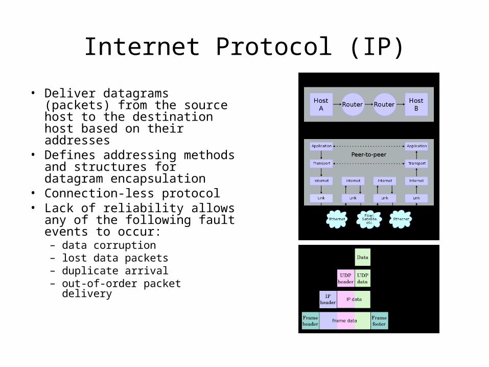
• Deliver datagrams (packets) from the source host to the destination host based on their addresses
• Defines addressing methods and structures for datagram encapsulation
• Connection-less protocol• Lack of reliability allows any of
the following fault events to occur:– data corruption– lost data packets– duplicate arrival– out-of-order packet delivery
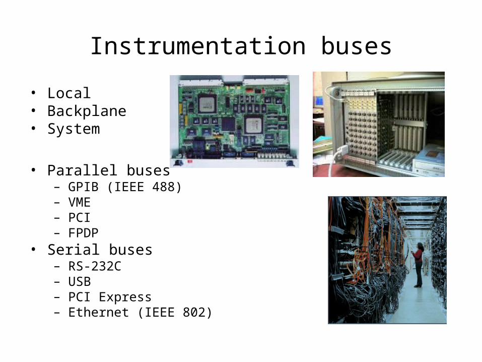
Instrumentation buses
• Local• Backplane• System
• Parallel buses– GPIB (IEEE 488)– VME– PCI– FPDP
• Serial buses– RS-232C– USB– PCI Express– Ethernet (IEEE 802)
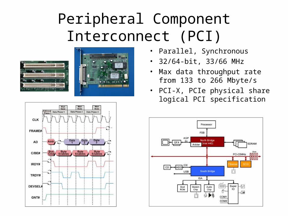
Peripheral Component Interconnect (PCI)• Parallel, Synchronous• 32/64-bit, 33/66 MHz• Max data throughput rate from
133 to 266 Mbyte/s• PCI-X, PCIe physical share logical
PCI specification
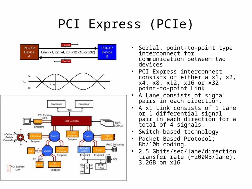
PCI Express (PCIe)
• Serial, point-to-point type interconnect for communication between two devices
• PCI Express interconnect consists of either a x1, x2, x4, x8, x12, x16 or x32 point-to-point Link
• A Lane consists of signal pairs in each direction.
• A x1 Link consists of 1 Lane or 1 differential signal pair in each direction for a total of 4 signals.
• Switch-based technology • Packet Based Protocol; 8b/10b
coding.• 2.5 Gbits/sec/lane/direction
transfer rate (~200MB/lane). 3.2GB on x16
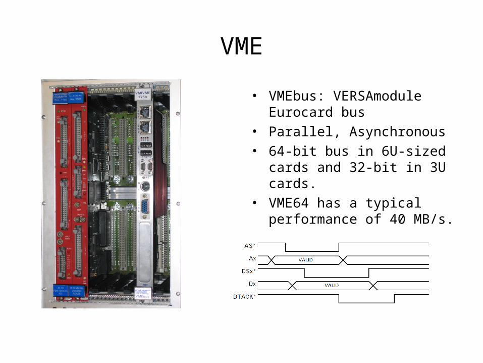
VME
• VMEbus: VERSAmodule Eurocard bus
• Parallel, Asynchronous• 64-bit bus in 6U-sized cards and
32-bit in 3U cards.• VME64 has a typical performance
of 40 MB/s.
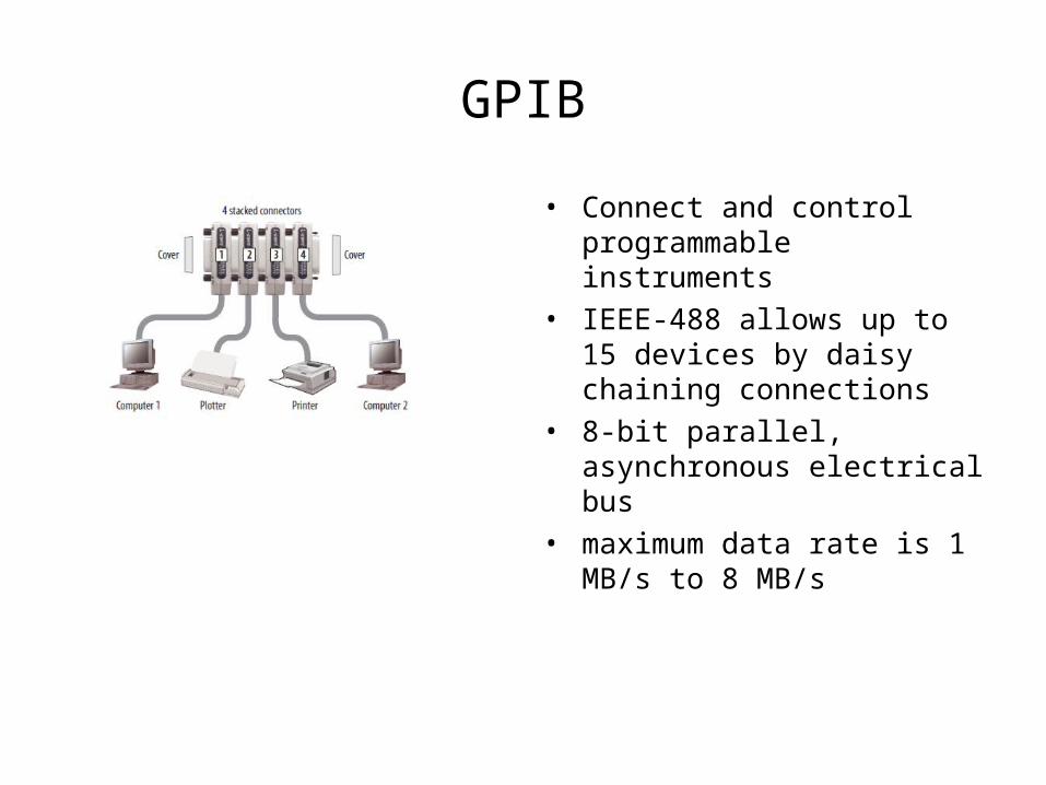
GPIB
• Connect and control programmable instruments
• IEEE-488 allows up to 15 devices by daisy chaining connections
• 8-bit parallel, asynchronous electrical bus
• maximum data rate is 1 MB/s to 8 MB/s
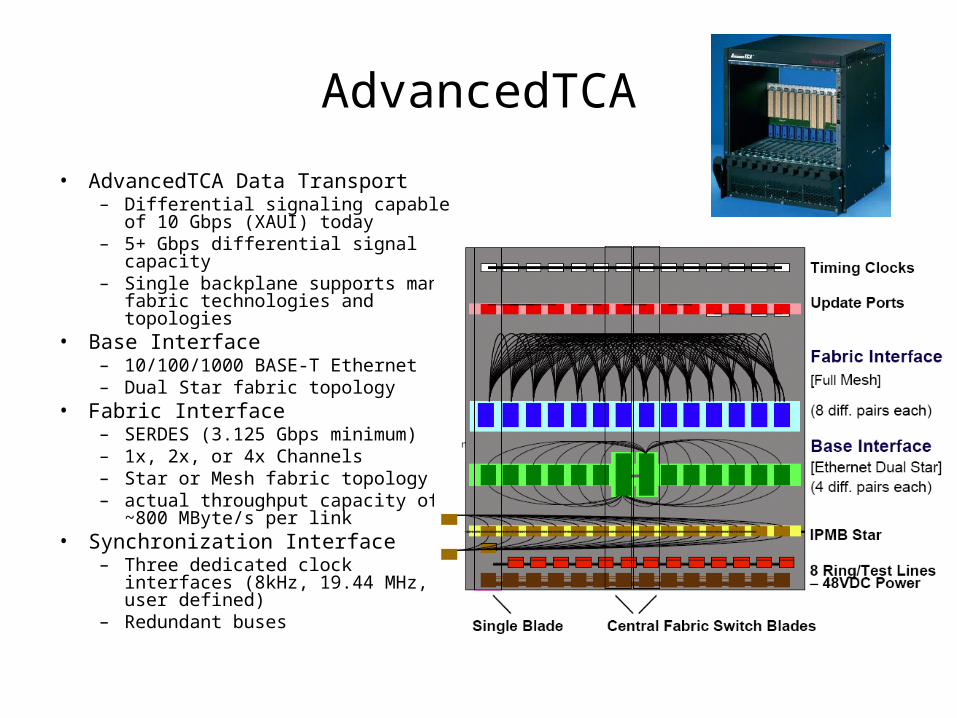
AdvancedTCA
• AdvancedTCA Data Transport– Differential signaling capable of 10
Gbps (XAUI) today– 5+ Gbps differential signal capacity– Single backplane supports many
fabric technologies and topologies• Base Interface
– 10/100/1000 BASE-T Ethernet– Dual Star fabric topology
• Fabric Interface– SERDES (3.125 Gbps minimum)– 1x, 2x, or 4x Channels– Star or Mesh fabric topology– actual throughput capacity of ~800
MByte/s per link• Synchronization Interface
– Three dedicated clock interfaces (8kHz, 19.44 MHz, user defined)
– Redundant buses
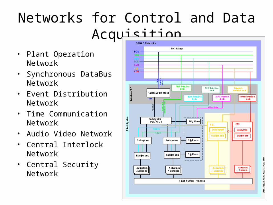
Networks for Control and Data Acquisition
• Plant Operation Network• Synchronous DataBus
Network• Event Distribution Network• Time Communication
Network• Audio Video Network• Central Interlock Network • Central Security Network
ITER_CODAC_PCDH_Figures_Visio_0011
Video Data
I&C Bridge
NTP
Actuators Actuators
Equipment
Subsystem
PSS
TCN InterfaceUnit
Equipment
Subsystem
PIS
SDN
AVN
EDNTCN
CSN
PON
SDN InterfaceUnit
Plant System Host
CLOCK
CODAC Networks
EVENTS
CM
D
ST
AT
US
Sensors SensorsActuators
/ SensorsActuators / Sensors
Digitizers
Digitizers
Digitizers
CIN
EquipmentEquipment
Subsystem Subsystem
Subsystem (PLC / PC )
Actuators / Sensors
Actuators
/ Sensors
Fie
ldb
us
EDN InterfaceUnit
AVN InterfaceUnit
Safety InterfaceUnit
Interlock Interface Unit
Plant System Process
Inte
rfa
ce
I&
C
Pla
nt
Sy
ste
m
DA
TA
/R
ea
l T
ime
F
ee
db
ac
k D
ata
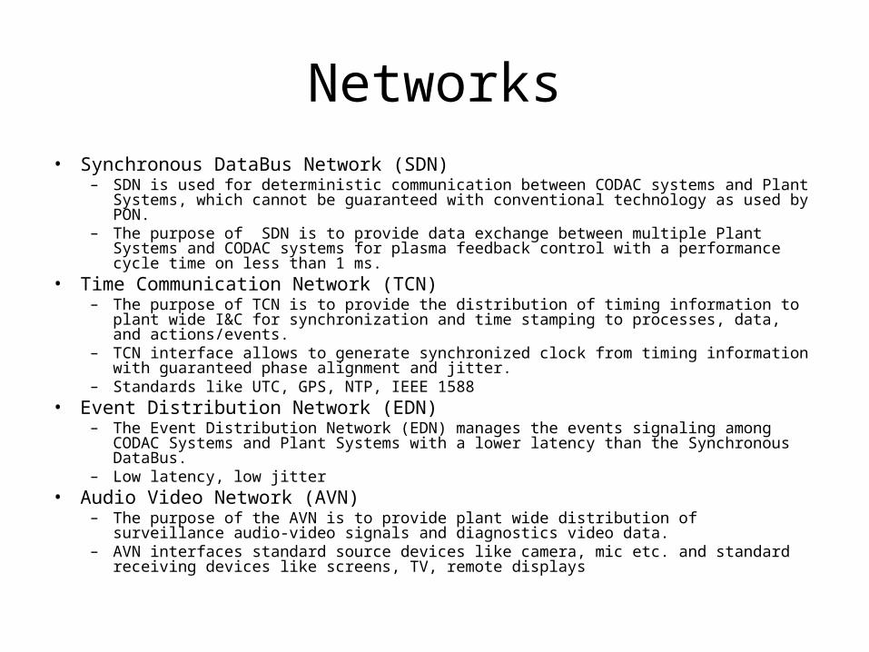
Networks• Synchronous DataBus Network (SDN)
– SDN is used for deterministic communication between CODAC systems and Plant Systems, which cannot be guaranteed with conventional technology as used by PON.
– The purpose of SDN is to provide data exchange between multiple Plant Systems and CODAC systems for plasma feedback control with a performance cycle time on less than 1 ms.
• Time Communication Network (TCN)– The purpose of TCN is to provide the distribution of timing information to plant wide I&C for
synchronization and time stamping to processes, data, and actions/events.– TCN interface allows to generate synchronized clock from timing information with guaranteed
phase alignment and jitter.– Standards like UTC, GPS, NTP, IEEE 1588
• Event Distribution Network (EDN)– The Event Distribution Network (EDN) manages the events signaling among CODAC Systems
and Plant Systems with a lower latency than the Synchronous DataBus.– Low latency, low jitter
• Audio Video Network (AVN)– The purpose of the AVN is to provide plant wide distribution of surveillance audio-video
signals and diagnostics video data.– AVN interfaces standard source devices like camera, mic etc. and standard receiving devices
like screens, TV, remote displays