Embed Size (px)
Citation preview

Mobile communications
2. GSM networks: services, architecture, functional
description

2.1 Introduction
❑initial vision was stated by GSM (Groupe Spéciale Mobile), a working group
established at Conférence Européenne des Administrations des Poste
et des Télécommunications (CEPT) -1982
❑later standardization was confined to a workgroup
SMG (Special Mobile Group) inside ETSI (European Telecommunications
Standards Institute)
-initial frequency bands were stated by the GSM working group:
890-915 MHz (uplink) and 935-960 MHz (downlink)
❑1991 GSM becomes Global System for Mobile Communications
includes both DCS1800 and PCS1900
❑major role in the standardization process :
GSM Memorandum of Understanding (MoU)
❑GSM standardization towards 3G is carried out by 3GPP – 3rd Generation
Partnership Project that unites several standard development organizations
Mobile communications
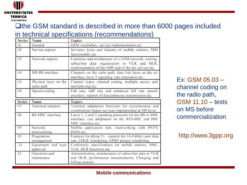
❑the GSM standard is described in more than 6000 pages included
in technical specifications (recommendations)
Ex: GSM 05.03 –
channel coding on
the radio path,
GSM 11.10 – tests
on MS before
commercialization
http://www.3gpp.org
Mobile communications
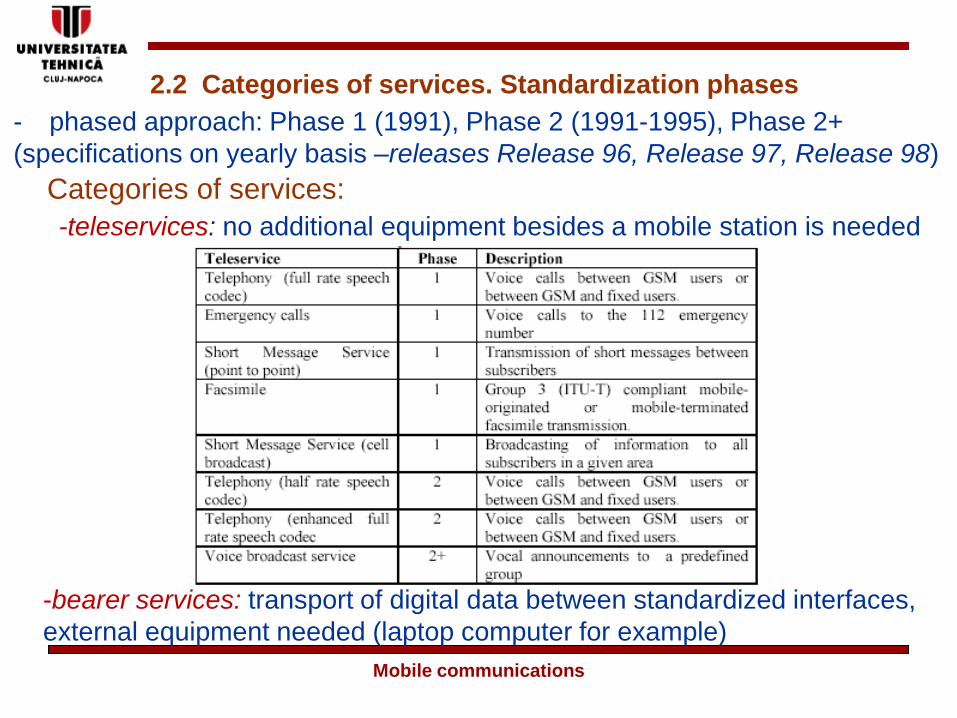
2.2 Categories of services. Standardization phases
Categories of services:
- phased approach: Phase 1 (1991), Phase 2 (1991-1995), Phase 2+
(specifications on yearly basis –releases Release 96, Release 97, Release 98)
-teleservices: no additional equipment besides a mobile station is needed
-bearer services: transport of digital data between standardized interfaces,
external equipment needed (laptop computer for example)
Mobile communications

-external connections are provided to/from the following networks
- PSTN – Public Switched Telephone Network
- ISDN – Integrated Services Digital Network
- CSPDN – Circuit Switched Public Data Network – dedicated data
networks compliant with the International Telecommunication
Union –Telecommunications (ITU-T) X.21 standard
- PSPDN – Packet Switched Public Data Network – dedicated data
networks compliant with the ITU-T X.25 standard
- Internet (only through PSTN or ISDN)
Mobile communications

-a network operator may opt to implement all bearer services or
only some of them – the 9.6 kbit/s asynchronous bearer service
the most popular
-supplementary services: additional features that are available or
not, depending on the operator’s choice to implement them, free of
charge or paid.
-except GPRS all of the GSM’s bearer service are based on circuit
switching CSD (circuit switched data)
Mobile communications

Some GSM supplementary services:
- network improvement is carried out also using a phased
approach: CAMEL, SOR etc.
Mobile communications

2.3 Mobility support in GSM networks
-GSM operates on a cellular structure
- GSM services are of circuit switched type: a voice or data call
uses dedicated resources till its completion
- a mobile station involved in an active call or using dedicated
resources for signaling purposes is said to be in dedicated mode
- a mobile station not have a physical channel allocated is in idle
mode- a mobile station that is switched off is said to be detached
- a mobile station that is switched on is said to be attached
❑ Terminal mobility (e.g. continuity for ongoing calls, connectivity
for following communications)
- handovers
- location management proceduresHard handovers are employed for ensuring continuity of ongoing
calls (the mobile station is in dedicated mode)
Mobile communications

- the handover decision is always taken by the network based on signal
strength measurements taken both by the network and the mobile station
(MAHO- Mobile Assisted HandOver) or based on load balancing algorithms
- during a handover process the mobile station stops transmitting on the
initial frequency and starts emitting again on a new channel allocated by
the network (usually) on another frequency
Location management procedures are employed for ensuring connectivity for
following communications (the mobile station is in idle mode)
- three methods can be employed in cellular systems for locating
the position of a mobile subscriber
-the mobile station indicates each change of cell to the network; its
position is known by the network on a cell per basis
-the mobile station indicates each change of position only when it
passes from a group of cells to another group of cells
-the position of the mobile station is not known
Mobile communications
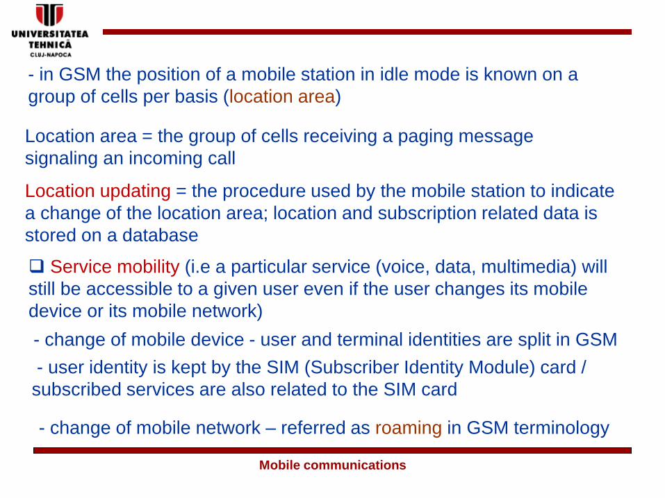
- in GSM the position of a mobile station in idle mode is known on a
group of cells per basis (location area)
Location area = the group of cells receiving a paging message
signaling an incoming call
Location updating = the procedure used by the mobile station to indicate
a change of the location area; location and subscription related data is
stored on a database
❑ Service mobility (i.e a particular service (voice, data, multimedia) will
still be accessible to a given user even if the user changes its mobile
device or its mobile network)
- change of mobile device - user and terminal identities are split in GSM
- user identity is kept by the SIM (Subscriber Identity Module) card /
subscribed services are also related to the SIM card
- change of mobile network – referred as roaming in GSM terminology
Mobile communications

- national roaming
- roaming within the GSM space
- non GSM roaming – the SIM card can be plugged into a non
GSM terminal; visited network must support SIM cards
The functions dealing with mobility are grouped in GSM in
broader contexts:
- radio resource management functions – including besides
handover and paging functions, specific channel
allocation/release functions.
- mobility management functions including besides location
updating some security related functions i.e. authentication
and ciphering.
Mobile communications
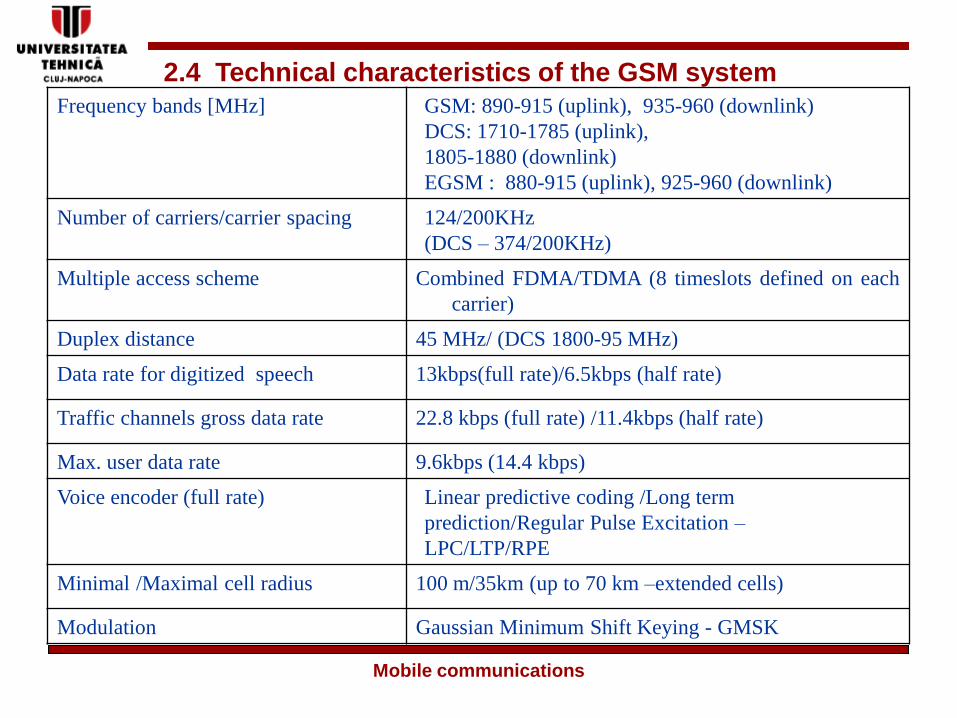
2.4 Technical characteristics of the GSM system
Frequency bands [MHz] GSM: 890-915 (uplink), 935-960 (downlink)
DCS: 1710-1785 (uplink),
1805-1880 (downlink)
EGSM : 880-915 (uplink), 925-960 (downlink)
Number of carriers/carrier spacing 124/200KHz
(DCS – 374/200KHz)
Multiple access scheme Combined FDMA/TDMA (8 timeslots defined on each
carrier)
Duplex distance 45 MHz/ (DCS 1800-95 MHz)
Data rate for digitized speech 13kbps(full rate)/6.5kbps (half rate)
Traffic channels gross data rate 22.8 kbps (full rate) /11.4kbps (half rate)
Max. user data rate 9.6kbps (14.4 kbps)
Voice encoder (full rate) Linear predictive coding /Long term
prediction/Regular Pulse Excitation –
LPC/LTP/RPE
Minimal /Maximal cell radius 100 m/35km (up to 70 km –extended cells)
Modulation Gaussian Minimum Shift Keying - GMSK
Mobile communications

MSC
2.5 The architecture of a GSM network
BTS
BTS
BSC MSC
BSC
VLR HLR AUC
EIR
GMSC
BSS
NSS
OMC
OMS
Um
interface
Abis
interface
A interface
X25
PSTN
ISDN
PSPDN
CSPDN
PLMN
IWF
MS
data/voice
signaling
MS

❑ SubsystemsBSS – Base Stations Subsystem
NSS – Network and Switching SubsystemOMS – Operation and Maintenance Subsystem
- each subsystem is composed of functional units (different equipments)
connected through standardized interfaces
BSS – several BTSs (Base Transceiver Station)
- a BSC (Base Station Controller)
- a TRAU (Transcoder and Rate Adaptation Unit)
NSS - MSC (Mobile Services Switching Centre)
- GMSC (Gateway Mobile Services Switching Centre)
- HLR (Home Location Register)
- VLR (Visitor Location Register)
- AuC- Authentication Centre
- EIR – Equipment Identity Register
OMS – OMC (Operation and Maintenance Centre)

2.5.1 Mobile Station
• MT (Mobile Termination) - equipment that provides all the
necessary functions for connections on the radio interface
• TE (Terminal equipment) - equipment directly in contact with
the user ( fax machine, desktop computer/ laptop / PDA); TE functionality
can be included in the MT
MT0
MT1
MT1
MT2
TE1
TATE2
TE2
• TA (Terminal adaptor)
-adaptation functions
4 wire ISDN
S interface
V24/RS 232 /emulated
serial interface
- MT0 – no TE connections
-MT1 allows connections of ISDN
terminals or non –ISDN (TE1/TE2)
-MT2 allows connections of non ISDN
terminals

• SIM card – subscriber identity module; microcontroller +
EEPROM/RAM memory, needed for operating a MS
- uniquely associated to a user/subscription and not to a mobile equipment
- contains static and non-static information such as:
➢ IMSI (International Mobile Subscriber Identity)
➢ secret authentication key (Ki)/ ciphering key (Kc)
➢ PIN/PUK codes
➢ TMSI (Temporary Mobile Subscriber Identity)
➢ Location information (LAI)
➢ List of forbidden PLMN’s/ list of licensed carriers (ARFCn)
➢ MSISDN (Mobile Station International ISDN number (optional)
➢ RAM like memory for storage of user directories/phone
numbers/SMS’s
- implements encryption (A8) and authentication (A3) algorithms
- the content of the SIM and its functionality
evolved during GSM’s standardization phases (phase 1, 2, 2+)

❑Base Transceiver Station (BTS)
• responsible for ensuring radio coverage on a given cell using a pair
or several pairs of duplex frequencies (typically up to 12 /cell in GSM)
• performs all signal processing tasks that an MS is performing except voice
coding and decoding
• implements multiplexing/demultiplexing functions for transmission over the
Abis interface
• provides measurement reports to BSC (for the uplink direction)
• a BTS is composed of
- several emitters/receivers (transceivers TRX (TRE)) operating each on
a pair of duplex frequencies
- a single or multiple omni directional or directional antennas
- a power unit (both AC supply and DC batteries)
- a local operation and maintenance unit
- duplexers (emission and reception paths on the same antenna) and
combiners (emission paths for multiple radio equipments on the same
antenna)

❑typical configuration with 4 TRX
combiners/duplexers
TRX1 TRX2 TRX3 TRX4
❑ includes an operation and maintenance unit
- controlled via BSC or locally using USB/serial connections
- handles the clock for the whole BTS
- clock usually derived from BSC; all BTSs are synchronized with the
later
BTSBTS

❑ typical connections to a BSC
- are done using a standard interface (the Abis interface)-
wired or wireless
- possible configurations
BSCBTS
BTS
BTS
BSCBTS
BTS
BTS
BSCBTS
BTS
BTS
star
loop (ring)
serial (chain)

❑Base Station Controller (BSC)
•“ intelligent” part of BSS
• connected to BTS via Abis and to MSC via the A interface
(or to TRAU via the Ater interface)
• manages radio channels in TRXs (allocation, release etc);
the channel allocation map is stored on a database
• manages the signaling channels of a MS: interprets them or relays
them if they are coming /going from NSS
• includes a digital switch network : switches channels from the Abis
interface onto channels on the A interface
• implements multiplexing/demultiplexing functions
• stores and allows software downloading to BTS
• often equipments inside BSS are provided by the same manufacturer -
> Abis interface is proprietary

• a BSC has an essential role for handovers
MSBTS1
BTS2
BSC
Measurement
report
(downlink)
Measurement
report (uplink)
Measurement
report
(downlink)
Channel
activation
Handover
command
Emission on
the new
channel
- in GSM the decision to perform a handover is always taken by
BSC using measurement reports

❑Transcoder and Rate Adaption Unit (TRAU)
•main functions: - voice transcoding from 13kbps to a 64kbps A law PCM - rate adaptation (8/16 kbit/s to 64 kbit/s)
- implements the GSM voice codec- involved in DTX mechanisms – insertion of comfort noise during
silent periods
MS BTS BSC MSCTRAU
13kbps 64kbps
MS BTS BSC MSCTRAU
13kbps 64kbps64kbps
MS BTS BSC MSCTRAU
13kbps 64kbps
Abis A
Abis A
Abis A
How to transport efficiently 13kbps channels using 64kbps channels?
•position inside BSS – left at the choice of the manufacturers/operators