Embed Size (px)
Citation preview

2 - Glossary of Terms5 - Worksheets
10 - Capacity Charts12 - Fork Arm Wear Caliper
17 - Fork Facts

■ GYPSUM HANDLING FORKS Provides optimum product protection when handling gypsum wallboard.
■ SHAFT FORKS To suit all pin type carriages.
■ DRUM FORKS Fast material handling of barrels and drums.
■ BLOCK FORKS Allows secure handling of bricks and blocks.
■ FOLDING FORKS These forks fold up to enable lift
trucks to maneuver in areas where movement is restricted. ie: elevators
■ FORK EXTENSIONS Used to extend the length of the fork blade when handling longer loads.
■ COIL HANDLING FORKS Blade is contoured to handle coils. Capacity is reduced according to the size of the contour.
Work Sheets Following To Speed Your Order
ENGINEERED FORK PRODUCTS
FORKS FOR NON-CURRENT VEHICLES Cascade has the world's largest database on fork
specifications for non-current lift trucks.
Call for information on forks fortrucks manufactured in the last 50 years.
■ STAINLESS STEEL CLAD FORKS For use in highly sanitary applications
such as the food and beverage industry.
■ LUMBER & PLYWOOD FORKS Forged heel, square heel, single taper, double taper, with or without Peek-A-Boo backs.
■ SPARK RETARDANT FORKS For hazardous locations and atmospheres.
Cascade makes forks for lift trucks of all makes, models and sizes – at a price that helps keep you competitive.
Our comprehensive product line includes a full range of fork products for a wide cross-section of industrial and commercial applications including:
■ QUICK DETACH FORKS Designed to be easliy and quickly removed from the lift truck carriage.
page 1
West: 800-227-2233 www.cascorp.com East: 877-227-2233
CascadeP.O. Box 20187
Portland, OR 97294-0187
800 227-2233503 669-6257
Fax 800 693-3768Serving: Alaska, Arizona, California, Colorado, Hawaii, Idaho, Montana, New Mexico, Nevada, Oregon, Utah, Washington, Wyoming, Mexico
CascadeP.O. Box 1508
Guelph, Ontario, Canada N1H 6N9
877 227-2233519 763-3675
Fax 519 763-1472Serving: North Dakota, South Dakota, Nebraska, Kansas, Minnesota, Iowa, Missouri, Wisconsin, Illinois, New York, Vermont, New Hampshire, Maine, Massachusetts, Connecticut, Rhode Island, Pennsylvania, New Jersey, Delaware, Maryland, Washington, D.C., Alabama, Arkansas, Florida, Georgia, Louisiana, North Carolina, South Carolina, Oklahoma, Tennessee, Texas, Virginia, Mississippi, Michigan, Indiana, Kentucky, West Virginia, Ohio
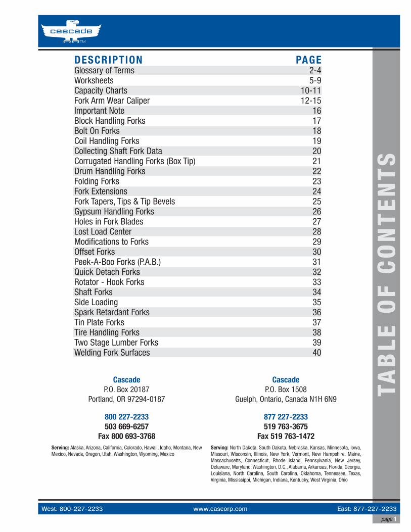
DESCRIPTION PAGEGlossary of Terms 2-4Worksheets 5-9Capacity Charts 10-11Fork Arm Wear Caliper 12-15Important Note 16Block Handling Forks 17Bolt On Forks 18Coil Handling Forks 19Collecting Shaft Fork Data 20Corrugated Handling Forks (Box Tip) 21 Drum Handling Forks 22Folding Forks 23Fork Extensions 24Fork Tapers, Tips & Tip Bevels 25Gypsum Handling Forks 26Holes in Fork Blades 27Lost Load Center 28Modifications to Forks 29Offset Forks 30Peek-A-Boo Forks (P.A.B.) 31Quick Detach Forks 32Rotator - Hook Forks 33Shaft Forks 34Side Loading 35Spark Retardant Forks 36Tin Plate Forks 37Tire Handling Forks 38Two Stage Lumber Forks 39Welding Fork Surfaces 40
TAB
LE O
F C
ON
TEN
TS

West: 800-227-2233 www.cascorp.com East: 877-227-2233 page 2
3.1.5
3.1.1
3.1.3
3.1.6
3.1.4
3.1.4
3.1.2
LIFT TRUCK FORKS VOCABULARY3.1.0 FORK PARTS3.1.1 BLADE
The horizontal portion of the fork upon which the load is supported.
3.1.2 HEEL The radiused portion of the fork connecting the blade to the shank.
3.1.3 SHANKThe upright (vertical) portion of the fork to which the supporting hooks are fixed.
3.1.4 HOOKS (or CLIPS, HANGERS)Lugs attached to the shank to support and retain the fork on the carriage. They may be made as non-integral hooks (attached to the shank) or as integral hooks (formed integrally with the shank)
3.1.5 TIP The free end of the blade.
3.1.6 POSITIONING LOCK (or PIN ASSEMBLY, LOCKING PIN)Device for locating the fork on the fork carriage.
GLO
SS
AR
Y O
F TE
RM
S

page 3
West: 800-227-2233 www.cascorp.com East: 877-227-2233
LIFT TRUCK FORKS VOCABULARY3.2.0 FORK SURFACES3.2.1 BLADE - UPPER FACE
The uppermost surface of the blade on which the load is carried.
3.2.2 HEEL - BOTTOMThe lower surfaces of the blade, including the tapers.
3.2.3 SHANK - FRONT FACEThe face of the shank which contacts the load and from which the load center distance is measured.
3.2.4 FLANKSThe side faces of the blade and shank.
3.2.5 HOOK RETAINING FACE The inclined faces of the top and the bottom hooks.
3.2.6 HOOK SUSPENSION FACEThe bottom horizontal face of the top hook in contact with the carriage or fork carrier.
3.2.7 TIP FLANKS (TOE FLANKS)The tip of blade sides which are shaped to facilitate insertion of the fork. (The tip shapes may take various forms )
3.2.8 SHANK TOPThe upper surface of the vertical (or shank)
3.2.9 SHAFTThe tube used for mounting forks onto shaft-type carriages.
3.2.7
3.2.1
3.2.33.2.6
3.2.5
3.2.5
3.2.4
3.2.2 3.2.2
3.2.8
3.2.9Top ofShank G
LOS
SA
RY
OF
TER
MS

West: 800-227-2233 www.cascorp.com East: 877-227-2233 page 4
L IFT TRUCK FORKS VOCABULARY3.3.0 FORK DIMENSIONS3.3.1 THICKNESS - T
The thickness of the parallel portion of the blade or shank closest to the heel.
3.3.2 WIDTH - WThe width of the blade.
3.3.3 BACK HEIGHT - BHThe distance from the bottom of the blade to the top of the shank.
3.3.4 LENGTH - BLThe length of the blade measured from the front of the shank to the extreme tip of the blade.
3.3.5 CROSS SECTION The product of the width and thickness.
3.3.6 ANGLE - AThe angle from the upper face of the blade to the front face of the shank.
BL
W
W
TT
BHA
Section A-A
A
A
GLO
SS
AR
Y O
F TE
RM
S
Cascade's Metric Program
Cascade has converted to metric cross sections. The actual size shipped will be the metric cross section and has no effect on the stated capacity. To convert metric to imperial, divide by the factor "25.4".
I.T.A. Hook Fork Capacity
Capacity ratings for I.T.A. Hook Forks are based on steel section size, hanger capacity and the lift truck class itself.

page 5
www.cascorp.com Toll Free: 877-227-2233 April 2009
General Notes:➀ Standard tips and tapers will be supplied, unless specific dimensions are given. Non-Standard requirements MAY be
more expensive.➁ Standard I.T.A. hooks and fork sizes are matched independently. Forks will always be rated to the related truck class capacity
in preference to the fork cross section size. Greater lifting capacity may be achieved by requesting our HEAVY DUTY hooks, which will however incur increased cost and delivery time.
Standard I.T.A. Forks
WO
RK
SH
EET
A
Dealer Name: Phone:b:
Contact Name: Fax:h1:
h2:
T:
W:
BL:
BH:
Truck Make:
Truck Model:
Truck Capacity:
Fork Capacity/Pair:
Load Center:
Mounting Class
DistanceBetween Hooks
Height of CarriageCheck Your
Choice
1 h2 12.05" 306mm b 13.00" 331mm
2 h2 15.04" 382mm b 16.00" 407mm
3 h2 18.78" 477mm b 20.00" 508mm
4 h2 23.54" 598mm b 25.00" 635mm
Email:

Toll Free: 877-227-2233 www.cascorp.com
page 6 April 2009
Dealer Name: Phone:
Contact Name: Fax:
Email:
b
h1
BH
T
BL
h2
z2
y1
y2
z1
w2
w1
x1
x2
w
General Notes:➀ Standard tips and tapers will be supplied, unless specific dimensions are given. Non-Standard requirements MAY be
more expensive.
Forks to fit square carriage platesW:
T:
BL:
BH:
Truck Make:
Truck Model:
Truck Capacity:
Fork Capacity/Pair:
Load Center:
WO
RK
SH
EET
B
b:
h1:
h2:
w1:
w2:
x1:
x2:
y1:
y2:
z1:
z2:
Pin Kit Required? Yes No (circle one)
If No, it is the user's responsibility to provide an acceptablemeans of fork retention REF: ANSI/ITSDF B56.1, 7.27.1

page 7
www.cascorp.com Toll Free: 877-227-2233 April 2009
Dealer Name: Phone:
Contact Name: Fax:
Email:
Shaft / Pin / Bar Type ForksW:
T:
BL:
BH:
CL:
Truck Make:
Truck Model:
Truck Capacity:
Fork Capacity/Pair:
Load Center:
INSETINLINE
OFFSET
CL
OS
TW
BL
ILIS
BH
General Notes:➀ Standard tips and tapers will be supplied, unless specific dimensions are given. Non-Standard
requirements MAY be more expensive.➁ Tube ID will equal bar diameter plus acceptable tolerance.➂ Tube OD: Excessively thin walls on the tube may require use of special tube material at extra cost.
Consult Cascade.
sl sdsw
TU
Section **
*
sa
OS:
IS:
IL: 0
Bar pin Ø:
Tube In Ø:
Tube Out Ø:
sa:
sd:
sl:
sw:
TU:
Is Tube Slotted? Yes No (circle one)
If Yes, show dimensions (sa to TU)
WO
RK
SH
EET
C

Toll Free: 877-227-2233 www.cascorp.com
page 8 April 2009
Dealer Name: Phone:
Contact Name: Fax:
Email:
BH
T
BL
W
d1
d2
d3
d4
e4
z
e1
e3
e2
DETAIL Z
Detail Z: 3 Bore/Hole type designs offered
Indicate thread size —————
e2e1
e3
Z1
e2
Z2
e2
Z3
Counterbore Drilled & Tapped ClearWO
RK
SH
EET
D
General Notes:➀ Standard tips and tapers will be supplied, unless specific dimensions are given. Non-Standard requirements MAY be
more expensive.
Bolt-On ForksW:
T:
BL:
BH:
Truck Make:
Truck Model:
Truck Capacity:
Fork Capacity/Pair:
Load Center:
d1:
d2:
d3:
d4:
e1:
e2:
e3:
e4:

page 9
www.cascorp.com Toll Free: 877-227-2233 April 2009
Fork Tips
No. 1 No. 2 No. 3
Chisel & Bevel Options
Tapers
Full Taper & Polishwith Top Bevel
Standard Taper,No Bevel
Full Taper & Polishwith Bottom Bevel
General Notes: No. 1 tip is standard on forks up to and including 7" (180mm).No. 2 tip is standard on Block Handling ForksNo. 3 tip is standard on forks wider than 7" (180mm).
Note: Other tips available. Please consult Cascade Sales.
Standard Taper Full Taper Full Taper & Polish Two Stage Lumber Taper & Polish W
OR
KS
HEE
T E

West: 800-227-2233 www.cascorp.com East: 877-227-2233 page 10
SHAFT FORKS Shaft Forks suit all pin type carriages
Capacity for rotator and inverted forks deduct 15%.For dimensions not listed, please call Cascade.
CA
PAC
ITY
CH
AR
T
Fork SizeWxT
Capacity/PairLbs. @ 24"Load Center
Capacity/PairLbs. @ 36"Load Center
Capacity/PairLbs. @ 48"Load Center
Fork SizeWxT
Capacity/PairKgs. @ 600Load Center
Capacity/PairKgs. @ 900Load Center
Capacity/PairKgs. @ 1200Load Center
Inches Millimeters4" x 1 1/4" 3,700 2,400 1,850 100 x 35 1,700 1,150 8503" x 1 1/2" 3,700 2,450 1,850 80 x 40 1,700 1,150 8504" x 1 1/2" 5,500 3,600 2,750 100 x 40 2,500 1,650 1,2505" x 1 1/2" 6,000 4,000 3,000 122 x 40 2,700 1,800 1,3506" x 1 1/2" 7,200 4,800 3,600 150 x 40 3,300 2,200 1,6507" x 1 1/2" 8,700 5,800 4,350 180 x 40 4,000 2,650 2,0008" x 1 1/2" 9,500 6,300 4,750 200 x 40 4,400 2,950 2,200
10" x 1 1/2" 12,200 8,150 6,100 250 x 40 5,600 3,750 2,80012" x 1 1/2" 14,300 9,550 7,150 300 x 40 6,600 4,400 3,30015" x 1 1/2" 18,100 12,050 9,050 380 x 40 8,350 5,550 4,2003" x 1 3/4" 4,900 3,300 2,400 80 x 45 2,300 1,700 1,1004" x 1 3/4" 6,100 4,050 3,050 100 x 45 2,800 1,850 1,4005" x 1 3/4" 7,600 5,000 3,750 122 x 45 3,500 2,250 1,7006" x 1 3/4" 9,200 6,100 4,600 150 x 45 4,200 3,200 2,1007" x 1 3/4" 10,800 7,200 5,400 180 x 45 5,000 3,350 2,500
4" x 2" 7,600 5,050 3,800 100 x 50 3,500 2,350 1,7505" x 2" 9,500 6,150 4,600 122 x 50 4,300 2,850 2,1006" x 2" 12,000 8,000 6,000 150 x 50 5,500 3,700 2,7507" x 2" 13,700 9,150 6,850 180 x 50 6,300 4,200 3,1508" x 2" 15,000 10,000 7,500 200 x 50 6,900 4,600 3,450
10" x 2" 18,900 12,600 9,700 250 x 50 8,700 5,800 4,35012" x 2" 22,600 15,050 11,300 300 x 50 10,400 6,950 5,20015" x 2" 28,600 19,050 14,300 380 x 50 13,200 8,800 6,600 18" x 2" 34,300 22,800 17,150 460 x 50 15,800 10,550 7,900
4" x 2 1/4" 10,950 7,300 5,500 100 x 60 5,050 3,350 2,5505" x 2 1/4" 13,700 9,150 6,850 125 x 60 6,300 4,200 3,1506" x 2 1/4" 16,300 10,850 8,150 150 x 60 7,500 5,000 3,750 7" x 2 1/4" 19,500 13,000 9,750 180 x 60 9,000 6,000 4,5004" x 2 1/2” 12,700 8,500 6,400 100 x 65 5,900 4,400 2,9005" x 2 1/2” 15,800 10,550 7,900 125 x 65 7,300 4,850 3,6506" x 2 1/2” 19,100 12,750 9,550 150 x 65 8,800 5,850 4,4007" x 2 1/2” 22,800 15,200 11,400 180 x 65 10,500 7,000 5,2508" x 2 1/2” 25,400 16,950 12,700 200 x 65 11,700 7,800 5,850
10" x 2 1/2” 31,800 21,200 15,900 250 x 65 14,700 11,000 7,30012" x 2 1/2” 38,200 25,500 19,100 300 x 65 17,600 13,200 8,80015" x 2 1/2” 48,000 32,000 24,000 380 x 65 22,000 14,650 11,0006" x 2 3/4" 22,100 14,750 11,050 150 x 70 10,200 6,800 5,1007" x 2 3/4" 26,500 17,650 13,250 180 x 70 12,200 8,150 6,1008" x 2 3/4" 29,500 19,650 14,750 200 x 70 13,600 9,060 6,800
10" x 2 3/4" 36,900 24,600 18,450 250 x 70 17,000 11,350 8,500 12" x 2 3/4" 44,300 29,550 22,150 300 x 70 20,400 13,600 10,200

page 11
West: 800-227-2233 www.cascorp.com East: 877-227-2233
Inches Millimeters
SHAFT FORKS
SHAFT MOUNTED BLOCK HANDLING FORKS
1 1/2" x 2" 3,000 2,000 1,500 2" x 2" 3,900 2,600 1,950
40 x 50 1,400 950 700 50 x 50 1,800 1,200 900
1. All forks rated above have a minimum safety factor of 3:1 with static load.
2. All ratings listed are per pair - Cascade forks are stamped per individual fork capacity as per ANSI/ITSDF B56.1-2005.
3. Capacities for non-standard sizes and load centers can be obtained from Cascade Sales.
Capacity for rotator and inverted forks deduct 15%.For dimensions not listed, please call Cascade.
Block Forks for pin type carriages.
Fork SizeWxT
Capacity/Pair Lbs.@ 24"
Load Center
Capacity/Pair Lbs.@ 36"
Load Center
Capacity/Pair Lbs.@ 48"
Load CenterFork Size
WxT
Capacity/Pair Kgs.
@ 600Load Center
Capacity/Pair Kgs.
@ 900Load Center
Capacity/Pair Kgs.@ 1200
Load Center
Shaft Forks suit all pin type carriages
CA
PAC
ITY
CH
AR
T
Fork SizeWxT
Capacity/PairLbs. @ 24"Load Center
Capacity/PairLbs. @ 36"Load Center
Capacity/PairLbs. @ 48"Load Center
Fork SizeWxT
Capacity/PairKgs. @ 600Load Center
Capacity/PairKgs. @ 900Load Center
Capacity/PairKgs. @ 1200Load Center
Inches Millimeters6" x 3" 27,400 18,250 13,700 150 x 75 11,700 7,800 5,8507" x 3" 30,600 20,400 15,300 180 x 75 14,100 9,400 7,0508" x 3" 33,900 22,600 16,950 200 x 75 15,600 10,400 7,800
10" x 3" 41,800 27,850 20,900 250 x 75 19,200 12,800 9,60012" x 3" 51,650 34,400 25,800 300 x 75 23,400 15,600 11,700
8" x 3 1/4" 43,400 28,950 21,700 200 x 85 20,050 13,350 10,050 7" x 3 1/2" 43,800 29,200 21,900 180 x 90 20,200 13,450 10,1008" x 3 1/2" 48,800 32,550 24,400 200 x 90 22,500 15,000 11,250 8" x 3 3/4" 54,500 36,350 27,250 200 x 95 25,100 16,750 12,550
8" x 4" 60,300 40,200 30,100 200 x 100 27,800 20,800 13,90010" x 4" 75,300 50,200 37,650 250 x 100 34,700 23,150 17,35012" x 4" 90,500 60,350 45,250 300 x 100 41,700 27,800 20,850
12" x 4 1/4" 109,400 72,900 54,700 300 x 110 50,400 37,800 25,2008" x 4 1/2" 79,650 53,100 39,825 200 x 115 36,700 24,450 18,350
10" x 4 1/2" 99,500 66,350 49,750 250 x 115 45,850 30,550 22,95012" x 4 1/2" 119,450 79,650 59,750 300 x 115 55,050 36,700 27,550
10" x 5" 117,800 78,550 58,900 250 x 125 54,300 36,200 27,15012" x 5" 141,200 94,100 70,600 300 x 125 65,100 48,800 32,500
12" x 5 1/2" 177,100 118,050 88,550 300 x 140 81,600 54,400 40,800 12" x 6" 203,350 135,550 101,700 300 x 150 93,700 62,450 46,850 14" x 6" 237,200 158,100 118,600 350 x 150 109,300 72,800 54,600

West: 800-227-2233 www.cascorp.com East: 877-227-2233 page 12
FOR
K A
RM
WEA
R C
ALI
PER
SUBJECT : FORK ARM WEAR CALIPER GUIDE
Fork Arm BladeCross Section
90%
A B
Measuring Fork Wear with Calipers
Fork calipers perform two tasks at once. They measure the thickness of the fork arm shank (A)then automatically indicate what a 10% wear factor would be when the calipers are applied to the blade cross section (B).
1. Checking Fork For Thickness WearForks should be inspected at least once a year (single-shift operation, and
more frequently in severe applications) for wear and distortion. The best
method is to use a fork caliper, which is a type of adjustable go/no-go gauge.
Each fork consists of two sections: the shank, which is the vertical part
attached to the carriage, and the blade, which is the portion that picks up
the load.
Set the front teeth of the jaws by measuring the thickness of the
shank (in an area of little or no wear) ensuring that the caliper is
held square across the shank (see figure A). Carefully remove the
caliper from the shank and position the jaws over the fork arm
blade approximately 50mm (2") out from the heel (see figure B).
If the inside teeth of the caliper hit the fork blade it has less than
10% wear and can be returned to service. If the inside teeth pass
freely over the blade the fork has 10% wear and 20% reduction in
capacity. Remove fork from service. See fork wear chart.
NOTE: Wear calipers are not recommended for full taper or lumber forks.
00 10 20 30 40 50Percentage Reduction in Blade Thickness
Per
cent
age
Rem
aini
ng o
f Spe
cifie
d C
apac
ity
60 70 80 90 100
10
20
30
40
60
50
70
80
90
100
This chart shows how fork wear reduces truck capacity. ANSI/ITSDF B56.1-2005 standards require that each fork be at least half the capacity of the truck at the rated load center distance as shown on the truck nameplate.Refer to ANSI Website: www.itsdf.org/pB56.asp
Fork Arm ShankCross Section
100%
OUTS
IDE
JAW
S 10
0%
INSI
DEJA
WS
90%

page 13
West: 800-227-2233 www.cascorp.com East: 877-227-2233
FOR
K A
RM
WEA
R C
ALI
PER
SUBJECT : FORK ARM WEAR CALIPER GUIDE2. Checking The Fork Heel AngleA. Open the calipers to approximately 90º and place the calipers in the top inside heel area of the
fork (on top of the blade).
B. Ensure that the 2 lower pieces on the horizontal leg are both touching the top of the blade.
C. Move the calipers towards the upright. Ensure that the caliper arms are both parallel to the blade
and to the upright.
D. Open/close the calipers so that the two similar extruding pieces on the vertical leg of the calipers
both touch the upright/shank of the fork.
E. When you are sure that all 4 points are simultaneously in contact with the fork, gently remove the
calipers and look at the indicator lines found at the top of the hinge pin.
If the line on the horizontal leg (that points vertically) is found to lie beyond either the 93º or 87º
indicator line, the forks should be marked to be checked for either permanent deformation, possible
stress cracks or any other defect that could impede the safe use of the fork.
NOTE: Some forks are intentionally built with the fork angle either smaller or greater than 90º. These forks will need to be inspected by other methods.

West: 800-227-2233 www.cascorp.com East: 877-227-2233 page 14
FOR
K A
RM
WEA
R C
ALI
PER
SUBJECT : FORK ARM WEAR CALIPER GUIDE3. Checking The ITA Hook For DefectsA. Select the correct Class ITA caliper-gauge for the appropriate ITA hook.
B. Insert the caliper-gauge up into the hook recess with the corresponding 20º angle face contacting
the 20º angle of the hook.
C. Press the vertical face flat against the fork upright/shank and move the caliper-gauge up into the
hook recess. The Caliper gauge must be held at 90º to the hook.
If the (lower) horizontal face of the caliper-gauge can go up high enough to make contact with
the lower lip surface on the hook, this would indicate that the 20º angle of the hook is worn or
deformed, and therefore the fork hook welds and fork heel area should be checked for cracks.

page 15
West: 800-227-2233 www.cascorp.com East: 877-227-2233
SUBJECT : FORK ARM WEAR CALIPER GUIDE4. Measuring the bore on shaft/pin type forks
Insert the reversed caliper inside the eye of the tube (see diagram 1) opening the teeth until
both sides of the teeth come in contact with the inside wall of the tube. Pull the caliper out and
measure the distance from tip to tip (see diagram 2).
FOR
K A
RM
WEA
R C
ALI
PER
Measure distancefrom tip to tip
Diagram 1
Diagram 2

West: 800-227-2233 www.cascorp.com East: 877-227-2233 page 16
IMPORTANT NOTE!The different forks and features shown in this catalog are informative only, and are displayed as examples of some of the many features we can provide. The adding or removing of any of these features to an existing fork/forks, can only be done by Cascade or an approved vendor.
When there are requirements for any new features, Cascade Engineering needs to be consulted to ensure that any additional work applied to the existing fork, will not impede it's intended capability or perhaps render it unsafe.
Prior approval for any work on Cascade forks is required from Cascade.
Please refer to the National Safety Standard:ANSI/ITSDF B56.1-2005, 6.2.16
SCOPEThe intention of the "Fork Facts" catalog is to:• Inform you of features we can provide for different fork applications• Assist you with technical data• Make you aware of the safety aspects related to building and using forks
IMP
OR
TAN
T N
OTE
!

page 17
West: 800-227-2233 www.cascorp.com East: 877-227-2233
FOR
K F
ACT
S ¦
BLO
CK
HA
ND
LIN
G
SUBJECT : BLOCK HANDLING FORKS
FEATURES1. The forged heel is enlarged (bent and upset manufacturing process) for maximum strength.
2. The inside heel area can be ordered with an optional special "concave type" radius that will reduce damage to the edges of the product.
3. Some applications may require our optional elongated tube (floating eye) so that when the load is being set down on an uneven surface, the forks first being relieved of the load can rise. This prevents damage to the product when the forks are withdrawn.
4. Block handling forks can be ordered in any length required and are manufactured with tube, hook, or floating eye mountings.
5. Typical section sizes used for block handling forks are 2 x 1.5" and 2 x 2". Special sizes are available upon request.
APPLICATIONBlock handling forks are used predominantly for lifting concrete or cement blocks in large numbers. They can be
ordered in sets as required, depending on the load-width, configuration, and weight.

West: 800-227-2233 www.cascorp.com East: 877-227-2233 page 18
FOR
K F
ACT
S ¦
BO
LT-O
N
SUBJECT : BOLT-ON FORKS
FEATURES1. Usually the fork is bolted all the way up the upright.
2. In most instances, the bolt-on design reduces deflection in the upright of the fork, thus reducing the overall deflection.
3. The forks can either be bolted on from the front or the back of the carrier.
4. If fitted from the front, the holes will be counter-bored / sunk to alleviate projection of the bolt heads and damaging product.
5. Obtaining the correct bolt-hole pattern for each set of forks is very important. If measuring the pattern up on-site, it is important to first identify if the bolt pattern is imperial or metric. Attachment make and model information is also helpful.
6. Bolt-holes should not be drilled on the outside heel radius. The start of a bolt hole pattern should begin at a minimum of 150mm above the top of the blade.
APPLICATION"Bolt -on forks" are attached to the
carriage (fork carrier) with bolts
instead of hooks or a tube. This
design greatly diminishes any
movement of the forks when loaded
or when the lift truck is in motion.
Front View
Counter Bored HolesTo Recess The BoltHead.
152.4Min. Height

page 19
West: 800-227-2233 www.cascorp.com East: 877-227-2233
FOR
K F
ACT
S ¦
CO
IL H
AN
DLI
NG
SUBJECT : COIL HANDLING FORKS
FEATURES1. A specific chamfer or radius size for the inside of the blades can be recommended.
2. A custom radius can be applied if desired to reduce damage to the product.
3. The top of the upright can also be rounded to reduce damage to the product.
4. The chamfers / radiuses required to the inside edges of the blades will affect the lifting capacity of the forks. Check with Engineering for details.
APPLICATIONChamfered or radiused coil handling forks are used to move steel coils, reels, etc when straddling the load is
desired. Other products, such as concrete pipes, can also be moved with this type of fork.
Inside edge of bladecan have a radius orchamfer as required.
Inside heel radius canbe modified to reducedamage to product.

West: 800-227-2233 www.cascorp.com East: 877-227-2233 page 20
FOR
K F
ACT
S ¦
COLL
ECTI
NG
SH
AFT
DAT
A SUBJECT : COLLECTING SHAFT FORK DATA
A. Use the vertical carriage edgefor all horizontal Dimensions.
G = Tube O.D. & I.D.
Tube locationK = D - ( B + C/2 )
BH
E
J
F
D
K
C = Pin O.D.
FEATURESA. Use the outer straight edge of the vertical carriage support at one side (left or right) as a common datum
to measure from.
B. Measure horizontally across to the front of the shaft that supports the fork.
C. Measure the diameter of the shaft. (Preferably away from the center of the shaft as it may be worn.)
D. Measure horizontally across to front face of the lower carriage bar.
E. Measure vertically from the underside of the shaft to the top of the lower carriage bar.
F. First check for wear on the underside of blade just in front of the outside heel, if there is no wear, lower the forks onto a flat smooth surface and measure from that surface up to the underside of the shaft to get a vertical dimension.
G. Measure the I.D. and O.D. of the tube. Check if the tube has a bushing in the I.D.
H. Check for any other restrictions for the tube that can limit the tube O.D. such as a top carriage cross-member.
J. Measure the carriage bar height.
K. Use the TUBE LOCATION formula above to establish; INSET, OFFSET or INLINE value.
APPLICATIONThe diagram shown is to assist in the collection of data for the fork
when ordering a shaft fork for a custom carriage.
(MEASURING THE CARRIAGE)

page 21
West: 800-227-2233 www.cascorp.com East: 877-227-2233
FOR
K F
ACTS
¦ CO
RR
UGAT
ED H
AN
DLI
NGSUBJECT : CORRUGATED HANDLING FORKS (Box Tip)
APPLICATIONCorrugated handling forks are primarily used to wedge under and to lift corrugated sheets that are resting on a
floor or similar flat surface, where there is no skid or spacer, separating it from this surface.
They can also be used for other types of product.
These forks can also be used to separate a load (such as thin steel plate, etc.) that has no spacers in between the
product to allow for easy entry, and exerts minimal to zero damage to the product..
FEATURES1. The fork blade is reduced in thickness at the tip to a sharp edge. The blade is “fully top
tapered”, and polished, thus providing a long easy transition in the thickness. The outside edges of the tip are rounded, again to allow for ease of entry.
2. This fork is also available with a “full bottom taper”, when the application requires it.
3. Available in many different widths.
3+0.0–1.5
Critical Dimension
(Full Top Taper)
Cascade Std. #3NB Tip
89.5º

West: 800-227-2233 www.cascorp.com East: 877-227-2233 page 22
FOR
K F
ACT
S ¦
DR
UM
HA
ND
LIN
G
SUBJECT : DRUM HANDLING FORKS
FEATURES1. The blades of each of the left and right hand fork have an arc cut-away on the inside edge of the blade
to match the drum diameter that is required.
2. Fork blades can be supplied with either one or two cut-outs.
3. The same forks can also be used for lifting conventional loads such as skids giving you a dual purpose attachment.
APPLICATIONDrum handling forks are designed to be used for lifting one or two drums at one time. Usually these forks are used
for moving the standard 45 gallon drum. Cascade can also provide forks for custom applications if the radius of the
drum should differ.
R 286

page 23
West: 800-227-2233 www.cascorp.com East: 877-227-2233
FOR
K F
ACT
S ¦
FOLD
ING
SUBJECT : FOLDING FORKS
FEATURES1. Folding forks consist of a blade, upright, pin and either a hook or shaft mount attachment.
2. There is a chain attached to a pin that wraps around the blade. The chain locks into a pin retainer to ensure the blade is held in the vertical position.
3. There are many variables to be considered when ordering a folding fork assembly, so please contact Engineering to assist you to design a safe and reliable product.
APPLICATIONFolding forks are designed to fold at the heel on a pin, allowing the blade to be placed in a vertical position, and
secured with a chain. Folding forks are often necessary when operating in a confined and restricted work
environment and for lift trucks that are transported to different work sites on trailers.

West: 800-227-2233 www.cascorp.com East: 877-227-2233 page 24
FOR
K F
ACT
S ¦
EXTE
NS
ION
S
SUBJECT : FORK EXTENSIONS
FEATURES1. Fork extensions are readily available to fit 100, 122, 150 and 180mm wide forks.
2. Fork extensions for the above widths can be acquired up to 2438mm long. (96")
3. Heavy-duty and any special extensions are available upon request.
4. Fork extensions are built in compliance with the ANSI/ITSDF Standard, B56.1-2005.
APPLICATIONFork extensions are used to compliment a fork that is lifting a load that is longer than the fork. Extensions
are designed for uniform loading; they should never be tip loaded. The length of the extension must not be
more than 1.5 x the length of the fork blade.
EG: Fork blade length=1219, (48")….Extension length=1829 (72")

page 25
West: 800-227-2233 www.cascorp.com East: 877-227-2233
FORK
FAC
TS ¦
TAPE
RS, T
IPS
& T
IP B
EVEL
SSUBJECT : FORK TAPERS, TIPS & TIP BEVELS
FEATURES1. Careful choice of a tip configuration will enhance the fork's functionality.
2. There are 2 commonly requested top tip profiles:- NO.1 & NO.3 (refer to diagram)
3. Tips can be ordered with or without a bevel.
4. Bevels can be requested. There are 4 basic designs (refer to diagram).
5. Tapers can be ordered as required. There are 4 basic designs.
6. A selection of the variables above can be custom ordered, recommended, or come standard with a specific fork requirement.
APPLICATIONFork tapers are required to enhance the ease of travel of the fork when engaged into a load.
Fork tips and tip bevels are required for ease of entry into a load, depending on the application.
These three features should be carefully selected when deciding on how the tip of the fork will
engage into a specific load.
C W
10 ±6
3 ±1.5
45 ±6
1.5 Max.
45 ±6
W90º
W = 100 to 300
R25 (Typ.) W B C 100 50 38 125 80 38 150 90 50 180 90 82
B
R16 (Typ.)
R200 (Typ.)
REF.No. 1
Standard Taper – No Bevel Standard Taper – With Bevel
Chisel TipStandard – Full Taper with Top or Bottom Bevel
No. 3
10 ±3
3+0.0–1.5
10 ±3
10 ±3
10 ±3

West: 800-227-2233 www.cascorp.com East: 877-227-2233 page 26
FEATURES1. Cascade's slide in Urethane pad is rated at 70 Durometer. The hardness of the Urethane pad is similar to
that of an automobile tire. Replacement pads are available. The pads are impervious to grease and do not mark the sheet as would other similar materials; it is extremely durable. The 70 Durometer pad is bonded to a steel plate for stability and rigidity. The slide-in feature of the pad makes replacement quick and simple, thus averting any expensive down time.
2. Hook or shaft type mountings are available to suit your lift truck.
3. Bent and Upset heel section
4. The blade is polished and all sharp corners removed (preventing damage to gypsum board).
5. There is a double sided bevel at the tip for easy entry between gypsum sheets.
6. Fork widths are normally up to 300mm (12").
7. Square corner in heel prevents damage to edge of gypsum sheet
8. High back support (if required)
FOR
K F
ACT
S ¦
GYP
SUM
HA
ND
LIN
G
SUBJECT : GYPSUM HANDLING FORKS
11
22
88
33
77
44
5
66
APPLICATIONGypsum handling forks have been specially designed by
Cascade with product protection in mind. The unique blade
design and vertical protective upright provides the optimum
product protection when handling gypsum wallboard or other
similar products.

page 27
West: 800-227-2233 www.cascorp.com East: 877-227-2233
FOR
K F
ACT
S ¦
HO
LES
IN
BLA
DES
SUBJECT : HOLES IN FORK BLADES
30075
HOLE POSITION:BETWEEN 75mm & 300mm MAX' FROM THE TIP
(NO HOLE)
HOLE IN CENTER
HOLE
TIP
FEATURESThe hole, or any lifting device in the hole, must not be used for pushing, pulling or side-loading, as a fork is an attachment that is designed for lifting and lowering only. Vehicles such as tractors are better suited for pushing and pulling applications.
Tip loading or prying with the tip is prohibited.
If you intend to have a 'hole feature' added to an existing fork:
• Please refer to the IMPORTANT NOTICE at the begining of the Fork Facts section.
• A new LOAD & LOAD CENTER must be established for this new lifting position, when a hook or similar lifting device is suspended from the hole.
APPLICATIONCascade can provide a drilled hole in the fork tip area. The hole size can be up to 25% of the blade width at the hole
location. The top and bottom of the hole will be countersunk to remove all sharp edges.

West: 800-227-2233 www.cascorp.com East: 877-227-2233 page 28
FOR
K F
ACT
S ¦
LOS
T LO
AD
CEN
TER
SUBJECT : LOST LOAD CENTER APPLICATION (Forks only, not at tachments)"Lost load center" is one of the terms assigned to describe the difference in distance between the fork thickness
that was originally designed for the lift truck and the new thicker fork required.
FOR EXAMPLE:
Original fork = 40mm thick,…new fork = 50mm thick,…therefore the "Lost load center" is:
40 - 50 = -10
The minus sign indicates "lost" and the 10 shows the difference.
This information is given back to the OEM who will recalculate the load and load center of the lift truck, which will
appear on the "capacity plate" of the truck.
FEATURESListed below are the average fork thicknesses for standard ISO forks for classes 2,3 & 4.
(Check specifications for the truck in question)
CLASS ORIGINAL FORK - NEW FORK = LOST LOAD DISTANCE
2 40mm -
3 50mm -
4 65mm -
Consult Engineering for all other enquiries.
There are also other changes to a fork which can cause a "movement forward" resulting in a lost load. These changes must also be taken into consideration.

page 29
West: 800-227-2233 www.cascorp.com East: 877-227-2233
FOR
K F
ACT
S ¦
MO
DIF
ICA
TIO
NS
SUBJECT : MODIFICATIONS TO FORKSAPPLICATIONModifications and additions shall not be approved by Cascade unless the changes are made by Cascade or
an approved supplier.
Refer to the diagram provided above for a complete understanding of the critical elements and locations on a fork. Refer to "Welding Fork Surfaces" for additional information.
Do not weld on these surfaces oron the sides within 13mm of thetop surface (refer to “Welding ForkSurfaces”).
Tube weld
Do not apply heatin the heel area.
Shaft Fork
Hook Fork
Bottom hook
Side weld
Tube weld
Lower weld
Top weld
Lower weld
Upper hook
Top weld
Side weld

West: 800-227-2233 www.cascorp.com East: 877-227-2233 page 30
FOR
K F
ACT
S ¦
OFF
SET
SUBJECT : OFFSET FORKSAPPLICATIONOffset forks are designed primarily for the purpose of enabling the forks on the lift truck to be wider than the
carriage (fork carrier). It is important to note that by doing this the load capacity of the fork will need to be
re-evaluated. Inset forks, which make the forks narrower than the carriage, can also be designed. Inset forks are
usually required to fit around a vertical centre support bar on the carriage. Consideration should be given to the load
now being carried on the extreme edges of the forks. This can impose some twisting and some additional load on
the edges of the hooks.
Original Fork Width
Normal ForkWidth
Offset ForkWidth
CarriageWidth
Fork Carriage (Carrier)
Fork Blade Typical
FEATURES1. When offset, the blades of the left and right hand extend further out than the upright portion of the fork.
Custom specifications will dictate what the required dimensions will be.
2. The opposite will apply to inset forks.

page 31
West: 800-227-2233 www.cascorp.com East: 877-227-2233
The cut out for theP.A.B. must be atleast 25mm abovethe carriage bar.
Carriage bar.
25mm
FOR
K F
ACT
S ¦
PEE
K-A
-BO
O (
P.A
.B.)
SUBJECT : PEEK-A-BOO FORKS (P.A.B. )
FEATURES1. Peek-A-Boo's or P.A.B. forks can be custom ordered to fit either in a predetermined pocket, with a wider
tube for stability or as per the end users request.
2. The lower part of the cut-away which forms the P.A.B. should never be less than 25mm above the top of the lower carriage bar.
APPLICATIONPeek-A-Boo forks have been developed primarily to increase the visibility of the lift truck driver. This type of fork
is usually wide, with a blade less than 50mm thick and used predominantly in the lumber industry. Reducing the
shank width is possible because the stress exerted on the fork, while lifting, diminishes gradually as one progresses
towards the top of the shank. All requests for P.A.B. forks should be confirmed with Engineering, as the cut out will
be dependent on the load.

West: 800-227-2233 www.cascorp.com East: 877-227-2233 page 32
FOR
K F
ACT
S ¦
QU
ICK
DET
AC
H (
Q.D
.)
SUBJECT : QUICK DETACH FORKSAPPLICATIONQuick Detach Forks are designed to be easily and quickly **removed from the lift truck's carriage when required.
The key feature is the upper hook which allows the fork to be removed without the need to remove the carriage/fork
'retaining bar', which would result in 'down time' for the lift truck.
This design is usually required for big forks that are difficult to handle due to their weight. Another reason may be
that the truck is capable of handling a different lifting tool for a different application ( E.G. - a coil ram), therefore
quick interchangeability is a huge time and financial advantage.
FEATURES1. Quick detach forks have an open style hook which could either fit over a round or square carriage bar.
2. Depending on the surface the truck is working on, (indoor surface or outdoor uneven surface) each fork may require a lower retaining fixture to prevent the fork from unintentionally disengaging.
3. **Owners and operators must ensure a safe and secured method and area for removing the forks. National Safety Guidelines must be adhered to, to prevent any accidents or injury.

page 33
West: 800-227-2233 www.cascorp.com East: 877-227-2233
FOR
K F
ACTS
¦ R
OTAT
OR
- H
OO
K F
OR
KSSUBJECT : ROTATOR - HOOK FORKS
APPLICATIONRotator hook forks are attached to a rotator attachment, which can invert the forks. Usually the forks fit into pockets
in a bin that needs to be tilted or inverted to empty the contents.
FEATURES Rotator Forks:1. Each fork has 3 'upper' hooks, one at the top, middle and bottom of the upright. (The lower hook would be on top when inverted, therefore it requires the strength of an 'upper' size hook).
2. The middle hook is at a special spacing (different for each of class 2, 3, & 4).
3. The capacity is reduced by 15% to compensate for the fork when in the inverted position.
77.5 +0.8–0.8
16.5Typ.
+1.5– 0.0
129 +1.0– 0.0
16.5Typ.
+1.0– 0.0
91.5 +0.8– 0.8
22Typ.
+1.0– 0.0
ITA Class 3A Mounting • 65G Rotator
ITA Class 2A Mounting • 40D - 55D Rotator
ITA Class 2A Mounting • 45G Rotator • 55G Rotator
119.5
22Typ.
+0.8– 0.8
149 +1.5–0.0
+1.0– 0.0 22
Typ.
+1.0– 0.0
216 +1.5– 0.0
26Typ.
+1.0– 0.0
ITA Class 4A Mounting • 120D - 150D Rotator
ITA Class 3A Mounting • 65D - 100D Rotator • 100G Rotator
ITA Class 3A Mounting • 80G Rotator

West: 800-227-2233 www.cascorp.com East: 877-227-2233 page 34
OS IS
Offset Inset
T BL
IL
WCL
Inline
OD
ID
FOR
K F
ACT
S ¦
SH
AFT
SUBJECT : SHAFT FORKS
FEATURESWhen ordering a shaft fork, the following information is important due to the variety of configurations in the field.
1. Truck make and model number.
2. CL: CENTER-LINE OF TUBE
3. IS: INSET, OS: OFFSET or IL: INLINE
4. T: thickness, W: width and BL: length of blade.
5. Outside and inside diameter of tube. (O.D. & I.D.)6. SD: Shaft diameter (fork carrier shaft pin diameter on carriage)
APPLICATIONShaft forks are used as an alternative to hook forks. They are also referred to as Pin Type forks. Shaft forks are more
readily found on larger lift trucks, although there are a number of small lift trucks with a pin type carriage. There are a
large variety of sizes of shaft forks to be found in the materials handling industry.
FORK SPECIFICATIONSClearance must exist between shaft and tube ID. CL To Centerline of Tube IS _______Inset OS __Offset IL 0" __Inline T Thickness W Width BL Length O.D. Outside Diameter I.D. Inside Diameter S.D. Shaft/Pin Diameter on Carriage
}Choose one style only. Dimension requ i red .

page 35
West: 800-227-2233 www.cascorp.com East: 877-227-2233
SUBJECT : S IDE LOADINGAPPLICATIONForks must not be used for side loading unless specially designed for a particular application. In order to produce
such a design, details of the load and load systems are required.
Specially designed hooks or tubes would probably be required if a special design was requested.
FOR
K F
ACT
S ¦
SID
E LO
AD
ING

West: 800-227-2233 www.cascorp.com East: 877-227-2233 page 36
FOR
K F
ACT
S ¦
SPA
RK
RET
AR
DA
NT
SUBJECT : SPARK RETARDANT FORKS
FEATURES1. The most popular spark retardant fork is covered in ASTM B36 alloy 6 brass that is 0.125" thick, (except
rear of upright and hooks) and brazed 100% along all seams.
2. Similarly coated forks (using stainless steel) are also available for the food industry though these are not spark retardant.
APPLICATIONSpark retardant forks are used on lift trucks operating in hazardous locations. These include places such as
chemical plants, grain elevators, mines, paint plants, munitions, arsenal manufacturing, and storage facilities.
B
B
B
B
B
B
B
NB
NB
NBNOTE: Surfaces labeled "B" have
brass coating.
Surfaces labeled "NB" do not have a brass coating.

page 37
West: 800-227-2233 www.cascorp.com East: 877-227-2233
FOR
K F
ACT
S ¦
TIN
PLA
TE
SUBJECT : T IN PLATE FORKS APPLICATIONTin plate forks are used to load can forming machines.
Righthand
Lefthand
Removableslide-in pad.Available inneoprene orpolyurethane.
Polished
Mounting - tubes, hooks, per request
FEATURES1. The tapered and offset tips are designed for easier entry into small skids.
2. The polyurethane backing is to protect the steel sheets from indentations, which could cause the forming machine to jam up and stop. The “slide in” polyurethane backing on the upright is removable and can also be supplied in neoprene.

West: 800-227-2233 www.cascorp.com East: 877-227-2233 page 38
FOR
K F
ACT
S ¦
TIR
E H
AN
DLI
NG
SUBJECT : T IRE HANDLING FORKSAPPLICATIONTire handling forks are used for lifting tires of all sizes. The blade can be custom shaped (profiled) for the variety of
sizes (radiuses) of tires on the market. If used in a tire recycling environment, there will be a variety of types and
sizes of tires to be handled. Where the damage to the load is not a priority, you could order a similar fork with a 45o
chamfer on the edge of the blade. This is a more economical option.
EconomicalOption
TireContour
45° Chamfer
Blade ShapedTo Tire Profile
FEATURES1. The blades of the left and right hand fork have a special radius, as specified by the end user, to the top
inside edge of each blade. The edges of this radius are finished with soft, round edges, so as not to damage new product.
2. These forks are usually fitted to the carriage (fork carrier) with bolts. It is imperative that the bolt pattern on the upright of each fork match that of the carrier. The bolt pattern on each fork must be accurately obtained from the end user in order to ensure that the blades match each other.

page 39
West: 800-227-2233 www.cascorp.com East: 877-227-2233
FOR
K F
ACT
S ¦
TWO
STA
GE
LUM
BER
SUBJECT : TWO STAGE LUMBER FORKS
FEATURES1. There is a two stage taper factored into the blade design.
2. There is a shorter but more durable slim tip for easy entry into the stack.
3. 10% of the blade near the inside of the heel is now at full thickness, providing increased rigidity.
4. 20% from the tip of the fork is now 50% of the full thickness of the blade, thus reducing fork deflection.
5. The top of the blade can be polished to reduce friction when engaging a load.
APPLICATIONThe use of 2" x 4" timber spacers, designed to separate lumber stacks has diminished in size over the years. This has
resulted in smaller spaces between the stacks. When handling longer or double depth stacks of lumber, a fully tapered
fork was tried, but was prone to deflection, causing unstable load conditions. Hence the two stage Lumber Tapered
Fork was developed to address and resolve these concerns. This design is recommended on forks 72" and longer.
Blade Length
20%of Blade Length
50% of BladeThickness
Blade Thickness
10%of Blade Length

West: 800-227-2233 www.cascorp.com East: 877-227-2233 page 40
FOR
K F
ACT
S ¦
WEL
DIN
G S
UR
FAC
ES
SUBJECT : WELDING FORK SURFACES
PLAN VIEW
Fork Blade
Block
Top ofForkUpright
Front Face of Upright
The block is welded to the plate andthe plates are welded to the upright
Plate
No Weld Closer Than13mm
DO NOT WELD WITHIN A MINIMUM OF 13mm (1/2") FROM THE SURFACES DESCRIBED ABOVE.ALSO SEE: "MODIFICATIONS TO FORKS"
APPLICATIONAny welding on a fork can effect the fork properties negatively.
The general rule is that there should be no welding on the top surface of the blade or the front face of the upright
(as they are in tension). Any deviation from this rule must always be discussed with Engineering so that the
appropriate safety margins can be applied.
There are a number of methods where applications can be adjusted to avoid welding in critical areas. For example
this block is welded at the side rather than the front.

EastToll Free: 877.227.2233Fax: 519.763.1472
P.O. Box 1508Guelph, OntarioCanada N1H 6N9
WestToll Free: 800.227.2233Fax: 800.693.3768
P.O. Box 20187Portland, OR 97294-0187
www.cascorp.com
Cascade is a registered trademark of Cascade Corporation. ©Cascade Corporation 2008 All Rights Reserved. Form# 6084904 2.5M CG 01/08