Embed Size (px)
Citation preview
2 D viewing
Prepared byElizabeth Isaac
DCS, RSET
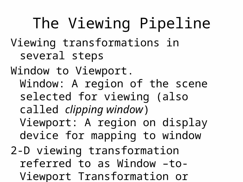
The Viewing PipelineViewing transformations in several stepsWindow to Viewport.
Window: A region of the scene selected for viewing (also called clipping window)Viewport: A region on display device for mapping to window
2-D viewing transformation referred to as Window –to-Viewport Transformation or windowing transformation
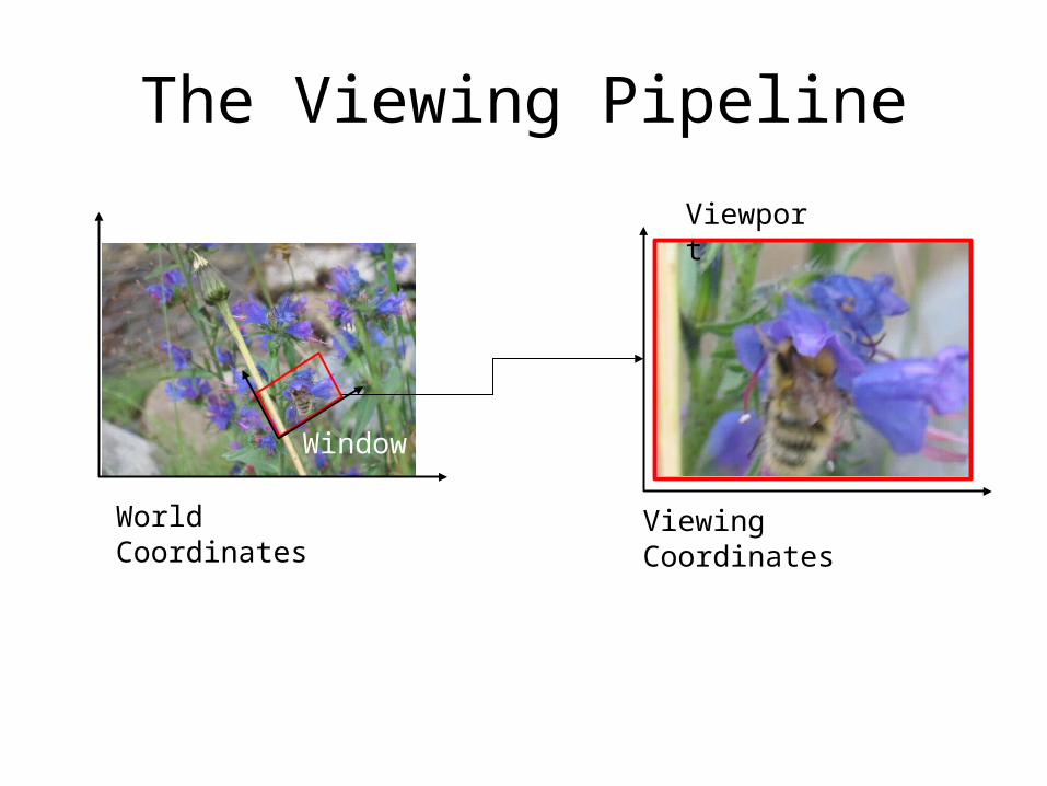
World Coordinates Viewing Coordinates
Window
Viewport
The Viewing Pipeline
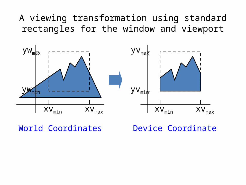
A viewing transformation using standard rectangles for the window and viewport
World Coordinates
xvmin xvmax
ywmax
ywmin
Device Coordinate
xvmin xvmax
yvmax
yvmin
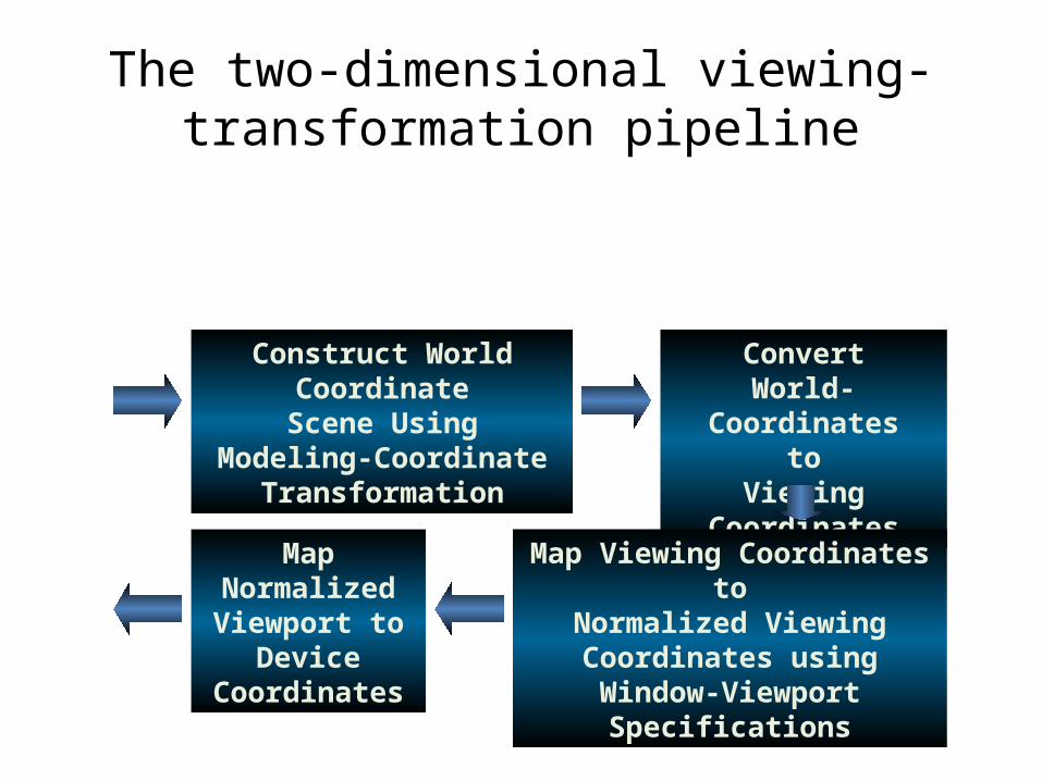
The two-dimensional viewing-transformation pipeline
Construct World CoordinateScene Using
Modeling-CoordinateTransformation
ConvertWorld-Coordinates
toViewing Coordinates
Map Viewing Coordinates toNormalized Viewing
Coordinates usingWindow-Viewport Specifications
Map NormalizedViewport to
DeviceCoordinates
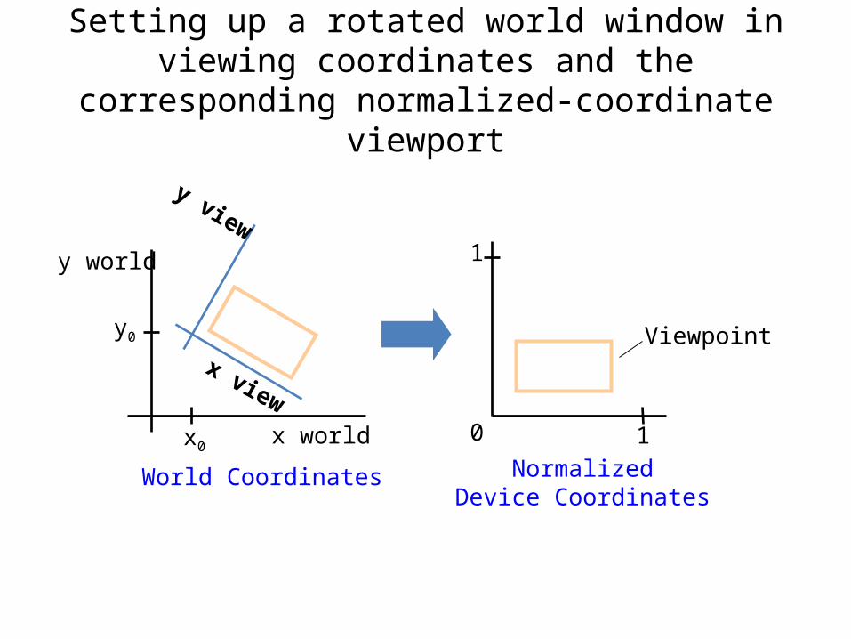
Setting up a rotated world window in viewing coordinates and the corresponding normalized-
coordinate viewport
NormalizedDevice Coordinates
Viewpoint
0 1
1
World Coordinates
y view
x view
y world
y0
x0 x world
Viewing Coordinate Reference Frame
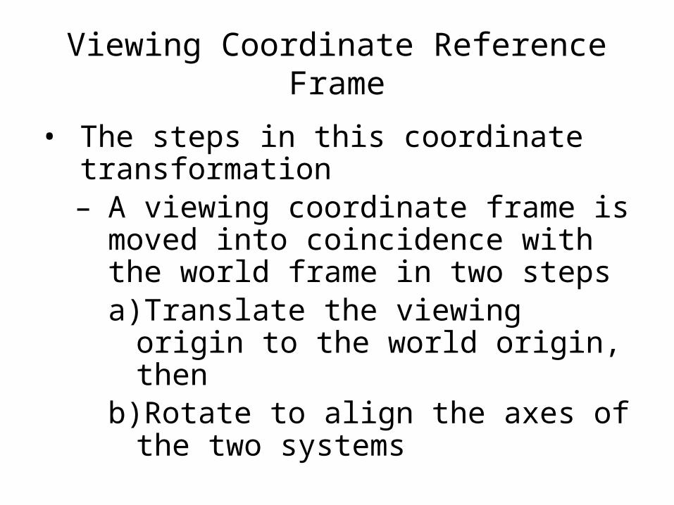
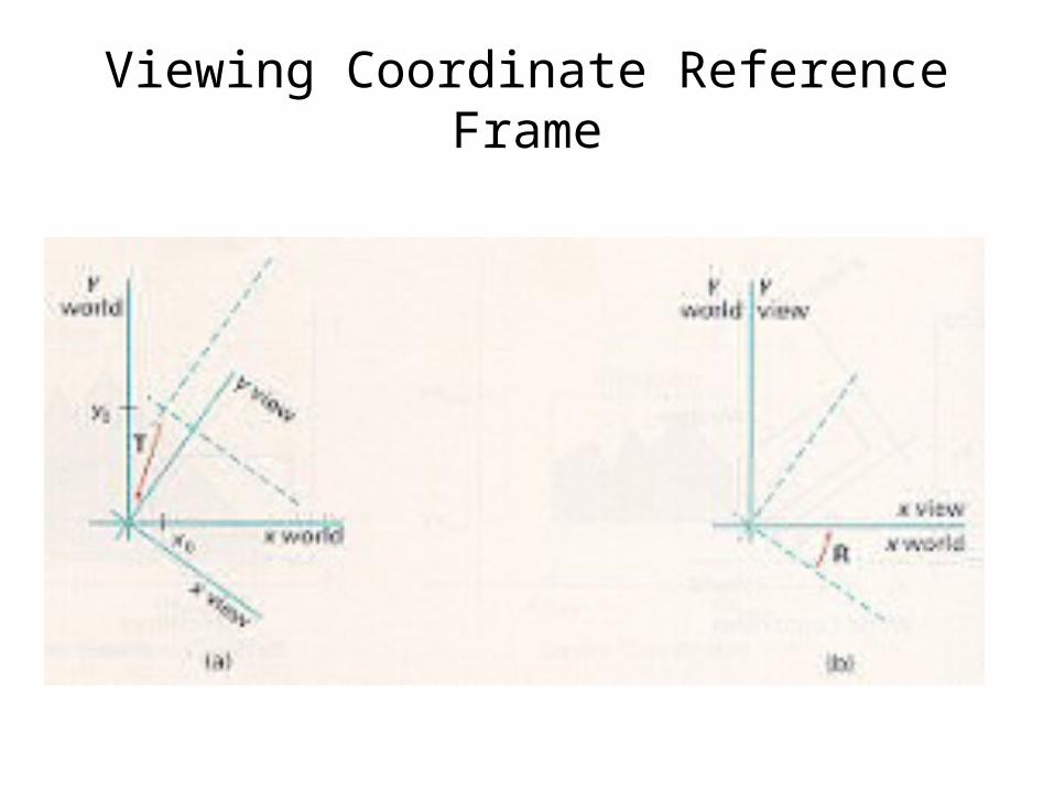
• The steps in this coordinate transformation– A viewing coordinate frame is moved into
coincidence with the world frame in two stepsa) Translate the viewing origin to the world
origin, thenb)Rotate to align the axes of the two
systems
Viewing Coordinate Reference Frame
Viewing Coordinate Reference Frame
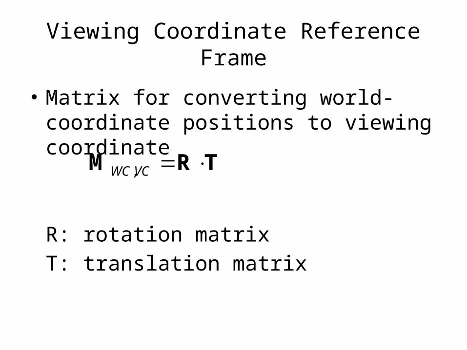
• Matrix for converting world-coordinate positions to viewing coordinate
R: rotation matrixT: translation matrix
ΤRΜ VCWC ,
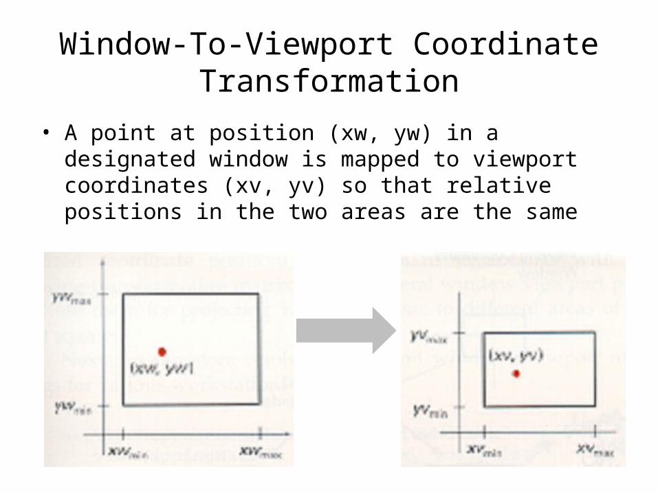
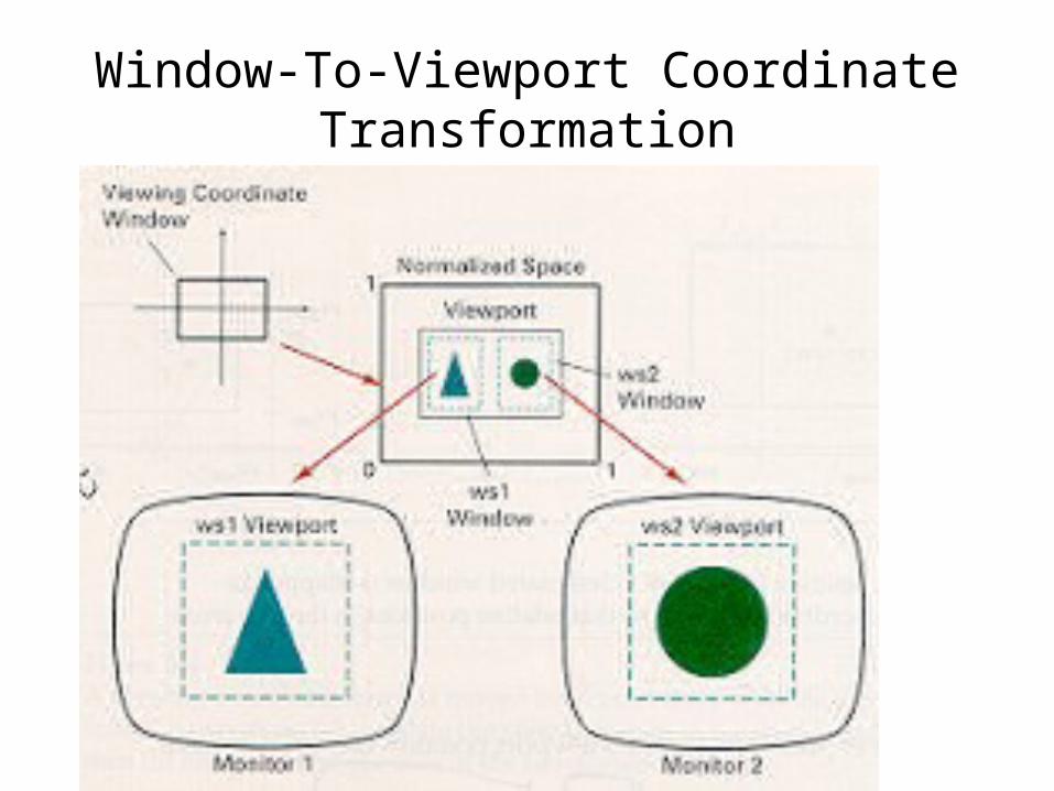
Window-To-Viewport Coordinate Transformation
• A point at position (xw, yw) in a designated window is mapped to viewport coordinates (xv, yv) so that relative positions in the two areas are the same
Window-To-Viewport Coordinate Transformation
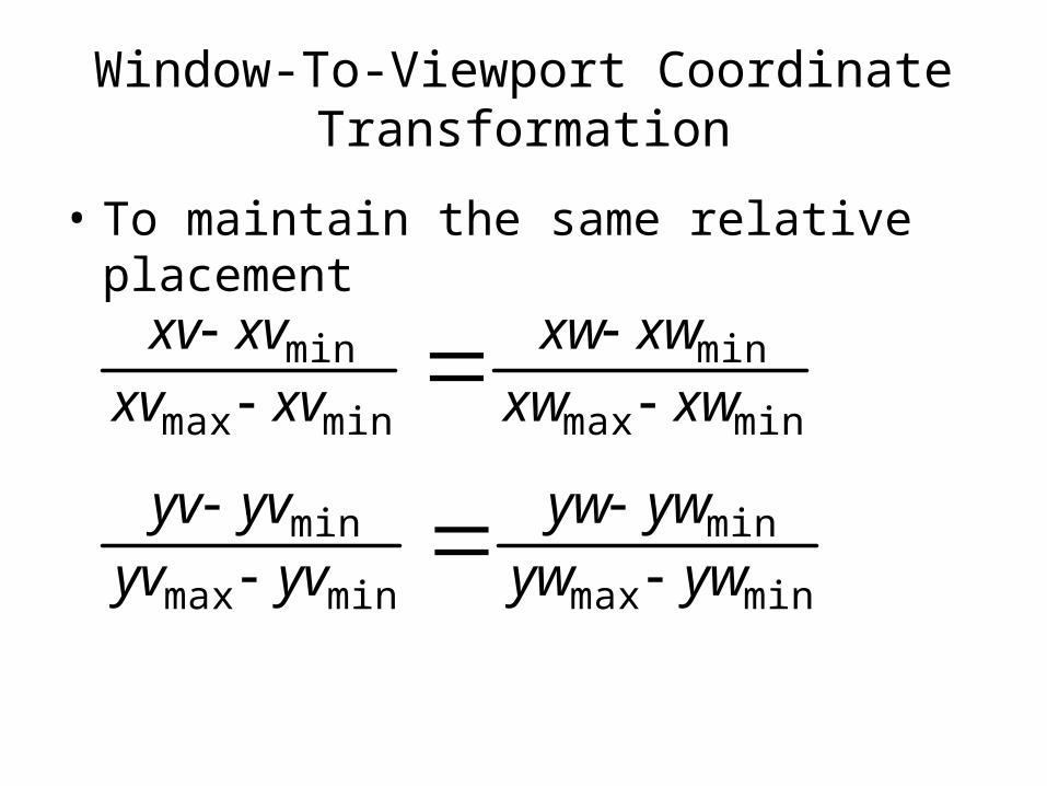
• To maintain the same relative placement
minmax
min
minmax
min
minmax
min
minmax
min
ywywywyw
yvyvyvyv
xwxwxwxw
xvxvxvxv
Window-To-Viewport Coordinate Transformation
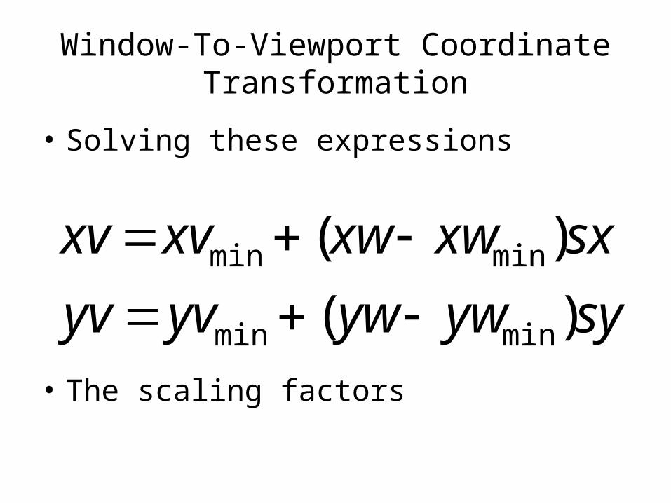
• Solving these expressions
• The scaling factors
syywywyvyv
sxxwxwxvxv
)(
)(
minmin
minmin
Window-To-Viewport Coordinate Transformation
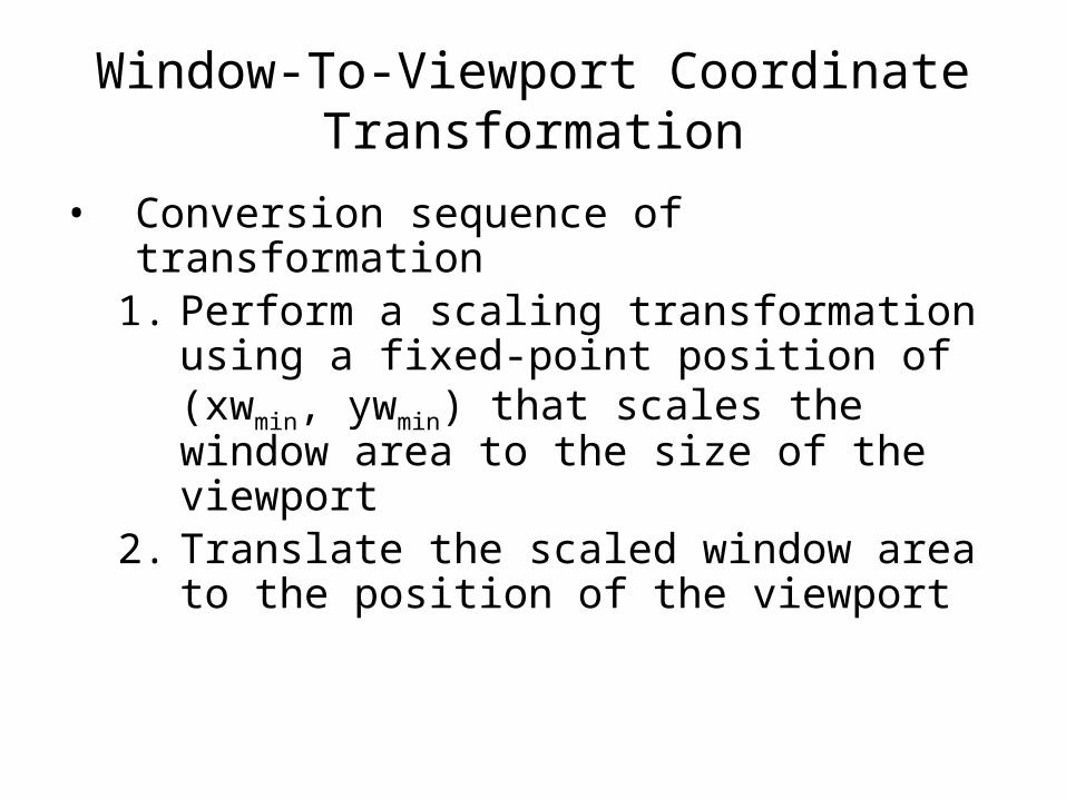
• Conversion sequence of transformation1. Perform a scaling transformation using a fixed-
point position of (xwmin, ywmin) that scales the window area to the size of the viewport
2. Translate the scaled window area to the position of the viewport
Window-To-Viewport Coordinate Transformation
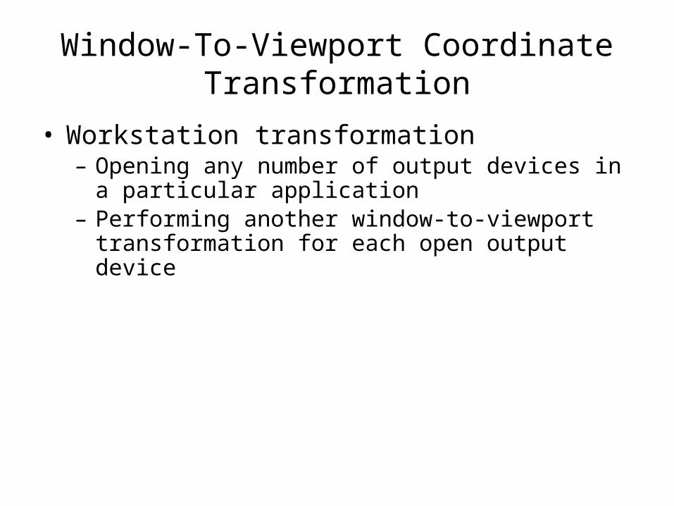
• Workstation transformation– Opening any number of output devices in a particular
application– Performing another window-to-viewport transformation
for each open output device
Window-To-Viewport Coordinate Transformation
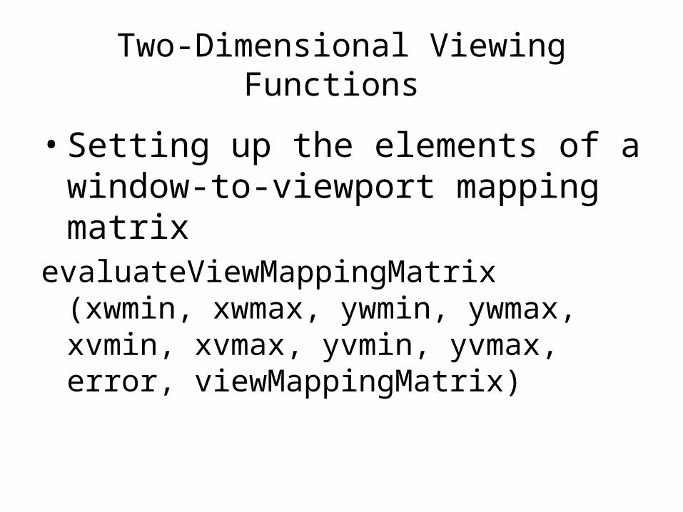
Two-Dimensional Viewing Functions
• Setting up the elements of a window-to-viewport mapping matrix
evaluateViewMappingMatrix (xwmin, xwmax, ywmin, ywmax, xvmin, xvmax, yvmin, yvmax, error, viewMappingMatrix)
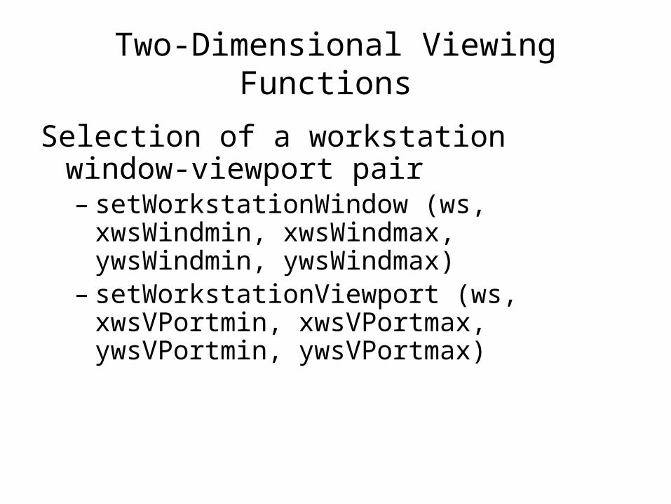
Two-Dimensional Viewing Functions
Selection of a workstation window-viewport pair – setWorkstationWindow (ws, xwsWindmin,
xwsWindmax, ywsWindmin, ywsWindmax)– setWorkstationViewport (ws, xwsVPortmin,
xwsVPortmax, ywsVPortmin, ywsVPortmax)
Clipping
Any procedure that identifies those portions of a picture that are either inside or outside of a specified region of space is referred to as a clipping algorithm or clipping
Clip window
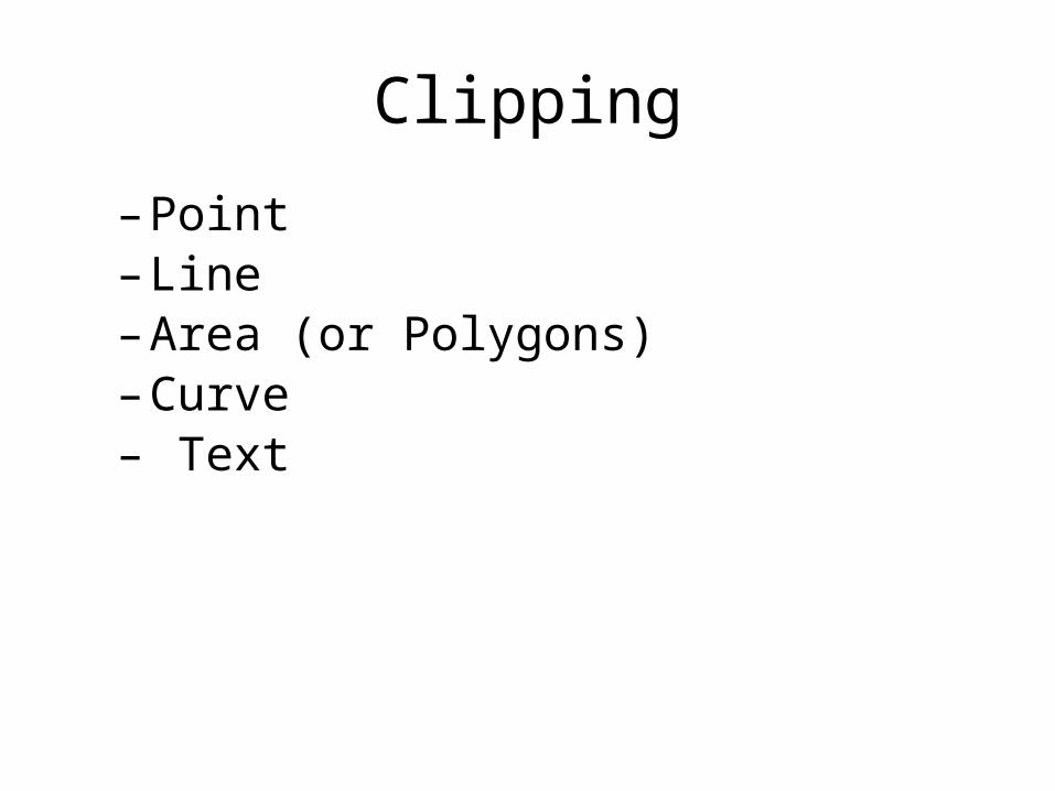
Clipping
– Point – Line– Area (or Polygons)– Curve– Text
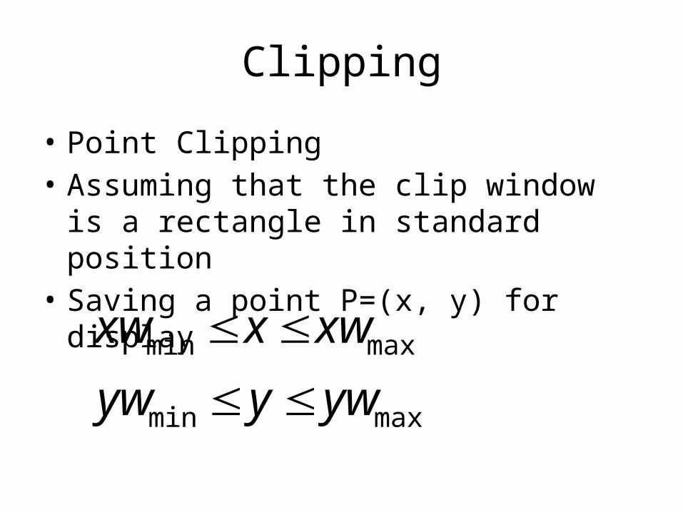
Clipping
• Point Clipping• Assuming that the clip window is a rectangle
in standard position• Saving a point P=(x, y) for display
maxmin
maxmin
ywyyw
xwxxw
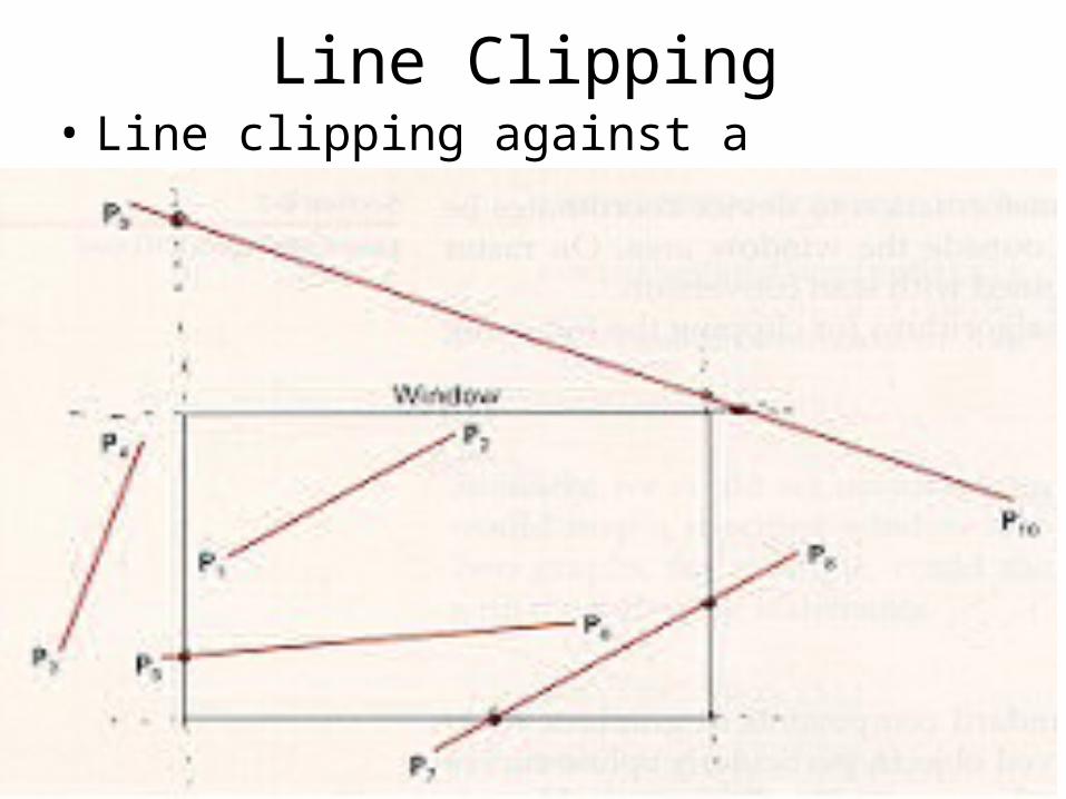
Line Clipping• Line clipping against a rectangular clip window
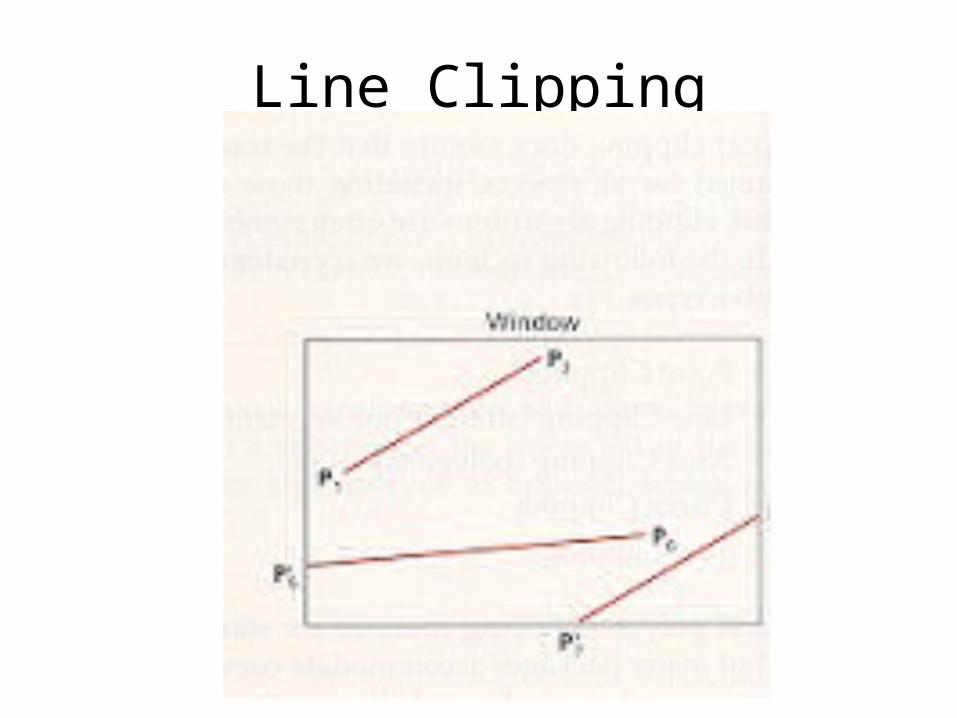
Line Clipping
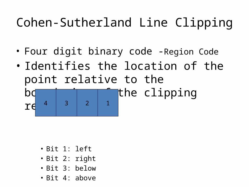
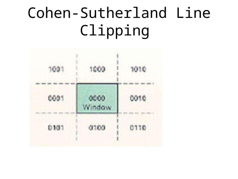
Cohen-Sutherland Line Clipping
• Four digit binary code -Region Code
• Identifies the location of the point relative to the boundaries of the clipping rectangle
• Bit 1: left• Bit 2: right• Bit 3: below• Bit 4: above
4 3 2 1
Cohen-Sutherland Line Clipping
Cohen-Sutherland Line Clipping
– Calculate differences between endpoint coordinates and clipping boundaries
– Use the resultant sign bit of each difference calculation to set the corresponding value in the region code
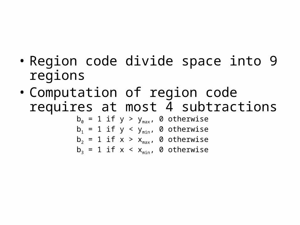
• Region code divide space into 9 regions• Computation of region code requires at most
4 subtractions
b0 = 1 if y > ymax, 0 otherwiseb1 = 1 if y < ymin, 0 otherwiseb2 = 1 if x > xmax, 0 otherwiseb3 = 1 if x < xmin, 0 otherwise
Cohen-Sutherland Line Clipping
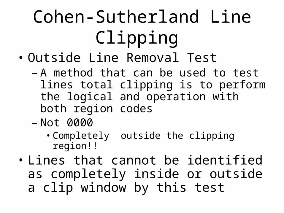
• Outside Line Removal Test– A method that can be used to test lines total
clipping is to perform the logical and operation with both region codes
– Not 0000• Completely outside the clipping region!!
• Lines that cannot be identified as completely inside or outside a clip window by this test
Cohen-Sutherland Line Clipping
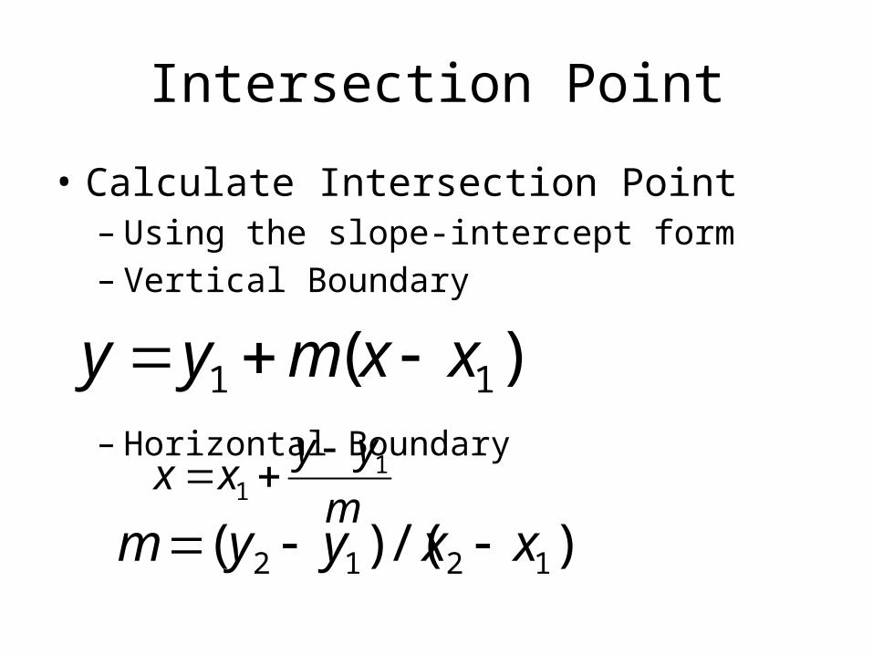
Intersection Point
• Calculate Intersection Point– Using the slope-intercept form– Vertical Boundary
– Horizontal Boundary
)( 11 xxmyy
m
yyxx 1
1
)/()( 1212 xxyym
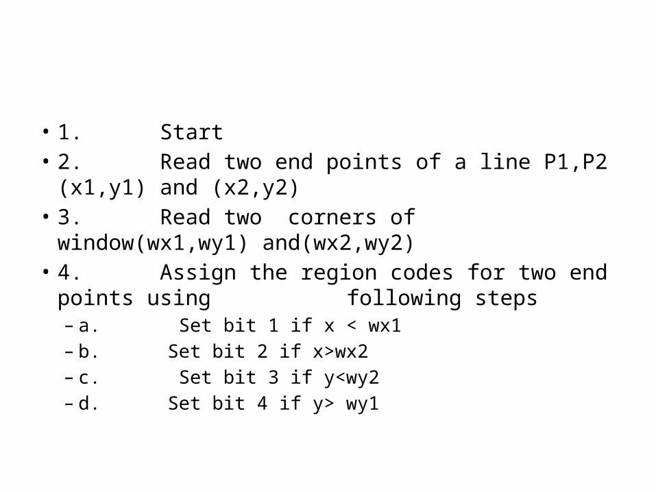
• 1. Start• 2. Read two end points of a line P1,P2 (x1,y1) and (x2,y2)• 3. Read two corners of window(wx1,wy1) and(wx2,wy2)• 4. Assign the region codes for two end points using
following steps– a. Set bit 1 if x < wx1– b. Set bit 2 if x>wx2– c. Set bit 3 if y<wy2– d. Set bit 4 if y> wy1
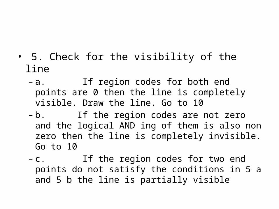
• 5. Check for the visibility of the line– a. If region codes for both end points are 0
then the line is completely visible. Draw the line. Go to 10
– b. If the region codes are not zero and the logical AND ing of them is also non zero then the line is completely invisible. Go to 10
– c. If the region codes for two end points do not satisfy the conditions in 5 a and 5 b the line is partially visible
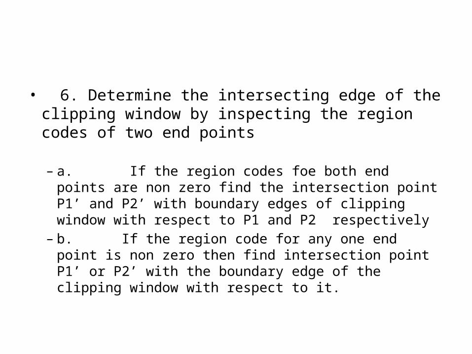
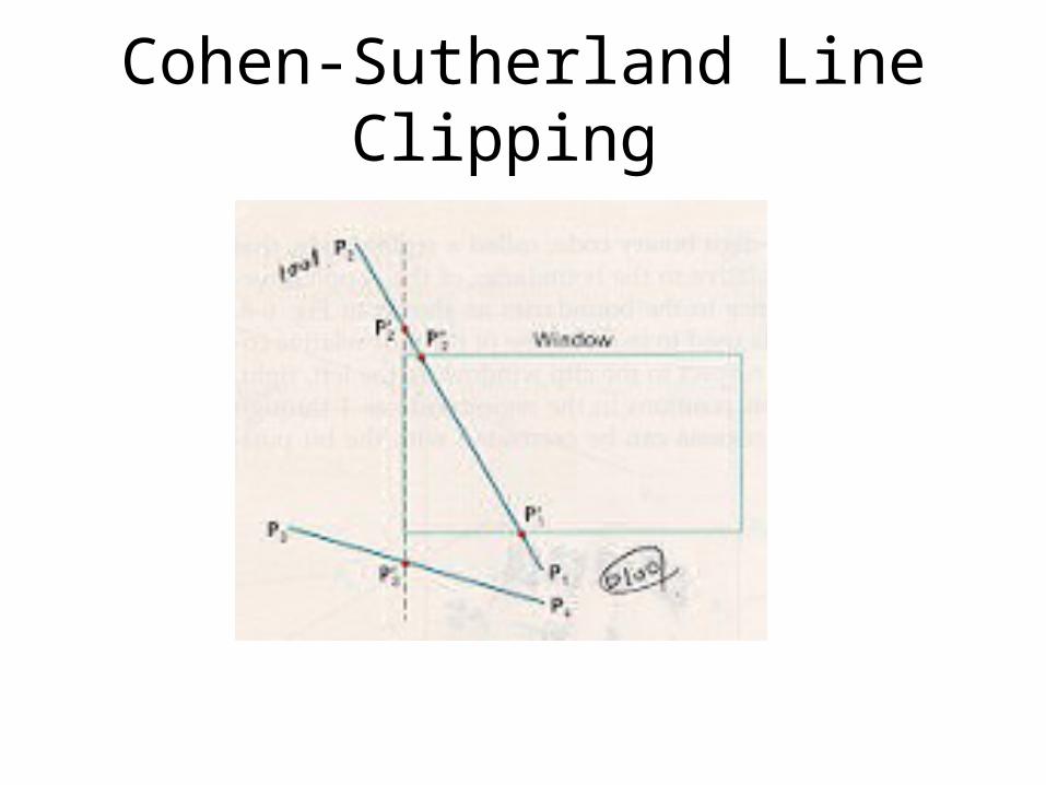
• 6. Determine the intersecting edge of the clipping window by inspecting the region codes of two end points
– a. If the region codes foe both end points are non zero find the intersection point P1’ and P2’ with boundary edges of clipping window with respect to P1 and P2 respectively
– b. If the region code for any one end point is non zero then find intersection point P1’ or P2’ with the boundary edge of the clipping window with respect to it.
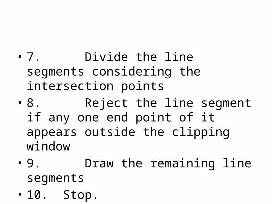
• 7. Divide the line segments considering the intersection points
• 8. Reject the line segment if any one end point of it appears outside the clipping window
• 9. Draw the remaining line segments• 10. Stop.
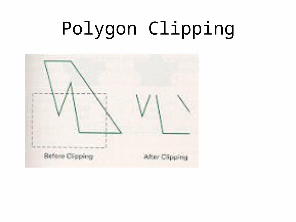
Polygon Clipping
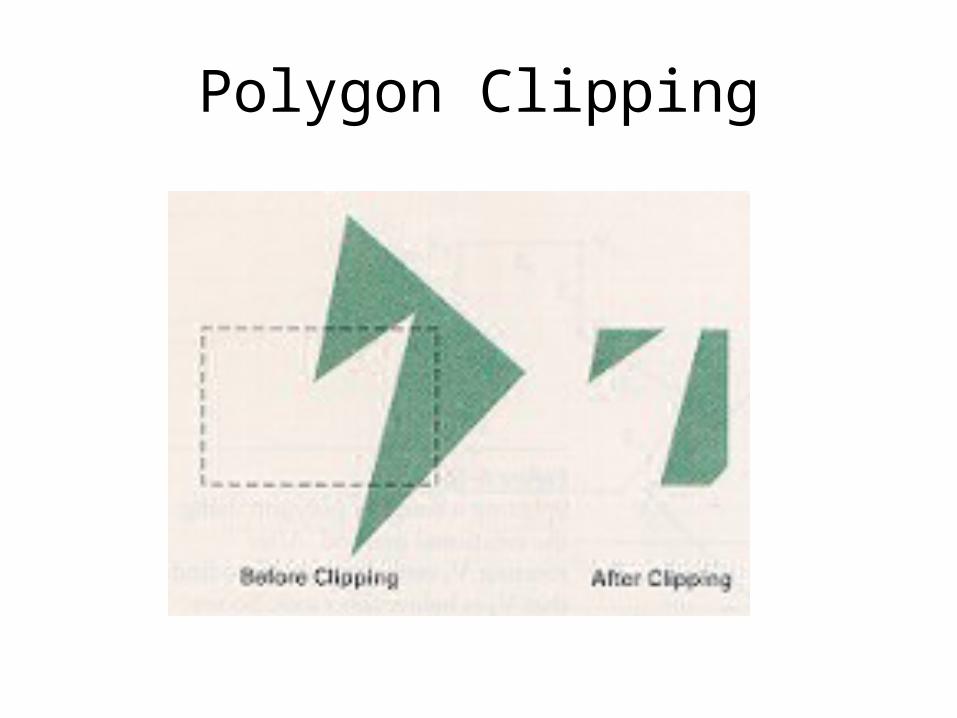
Polygon Clipping
36
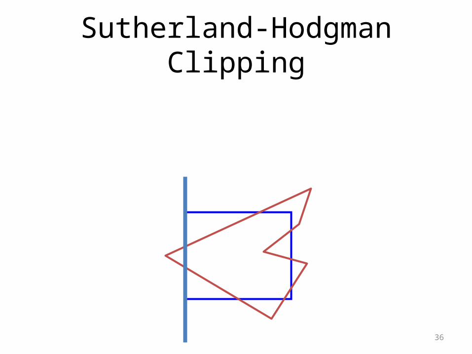
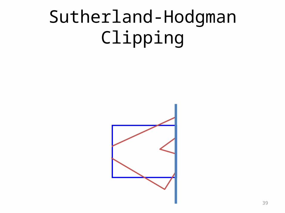
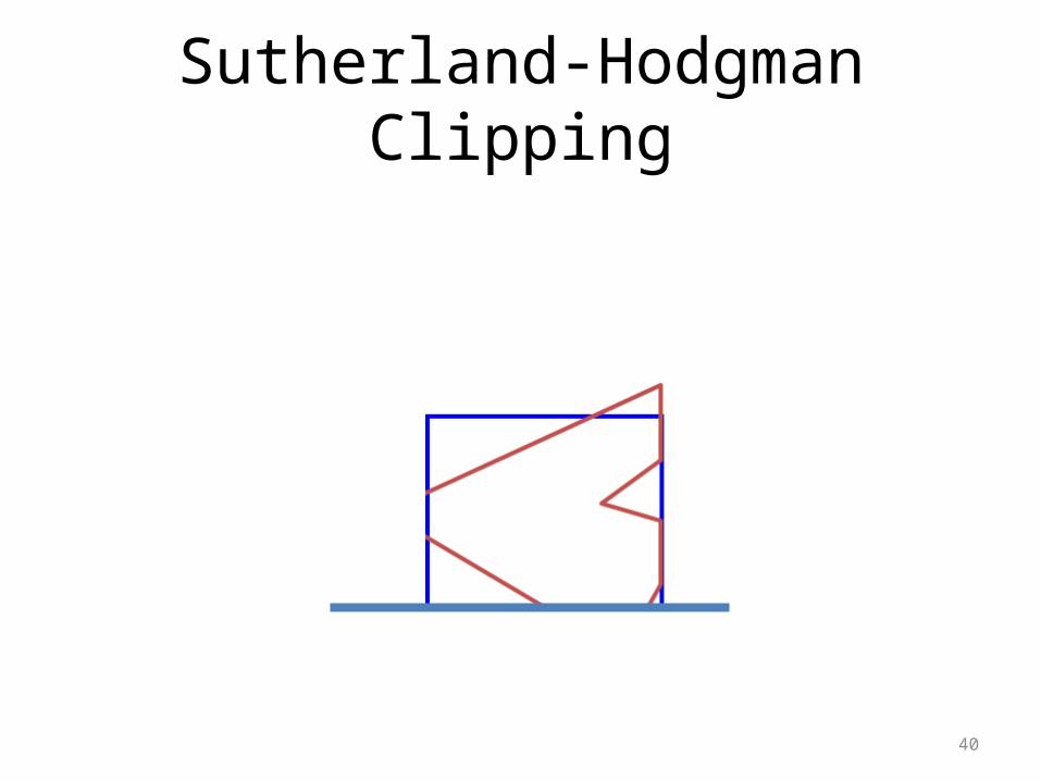
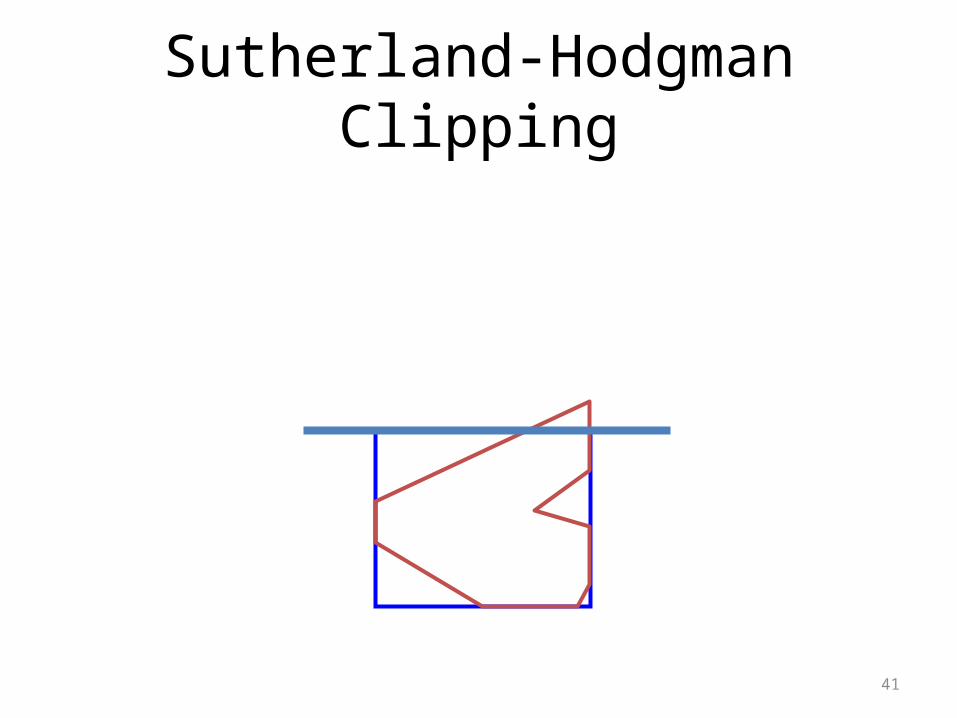
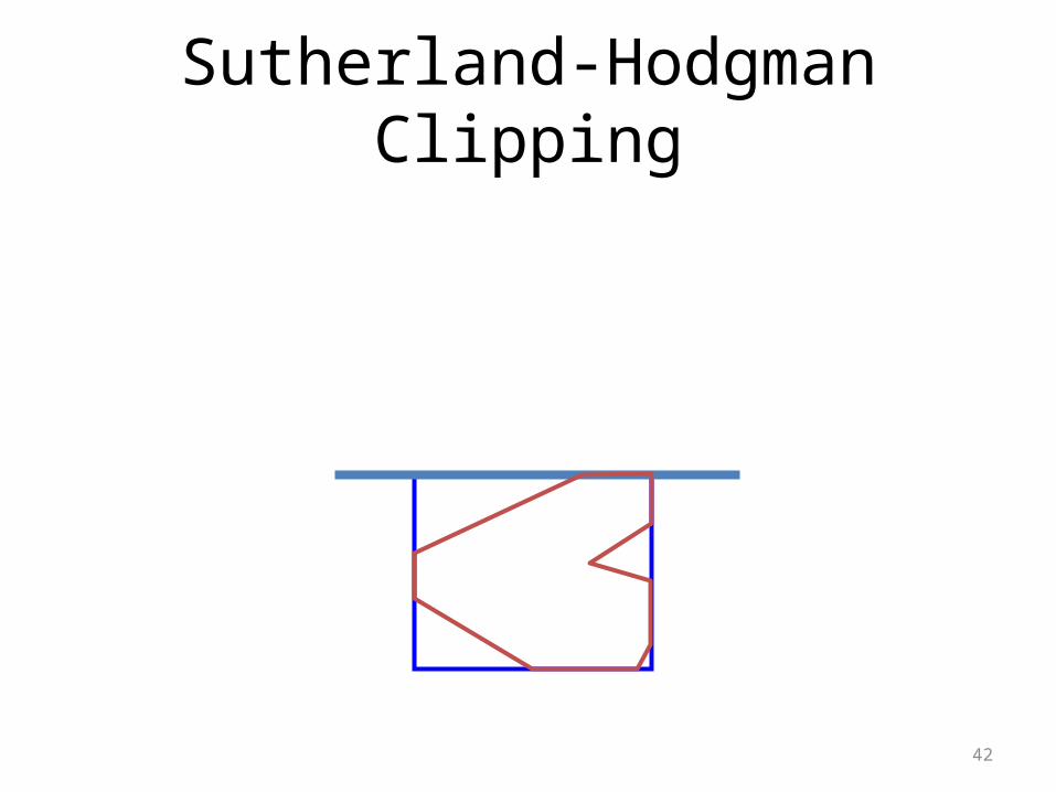
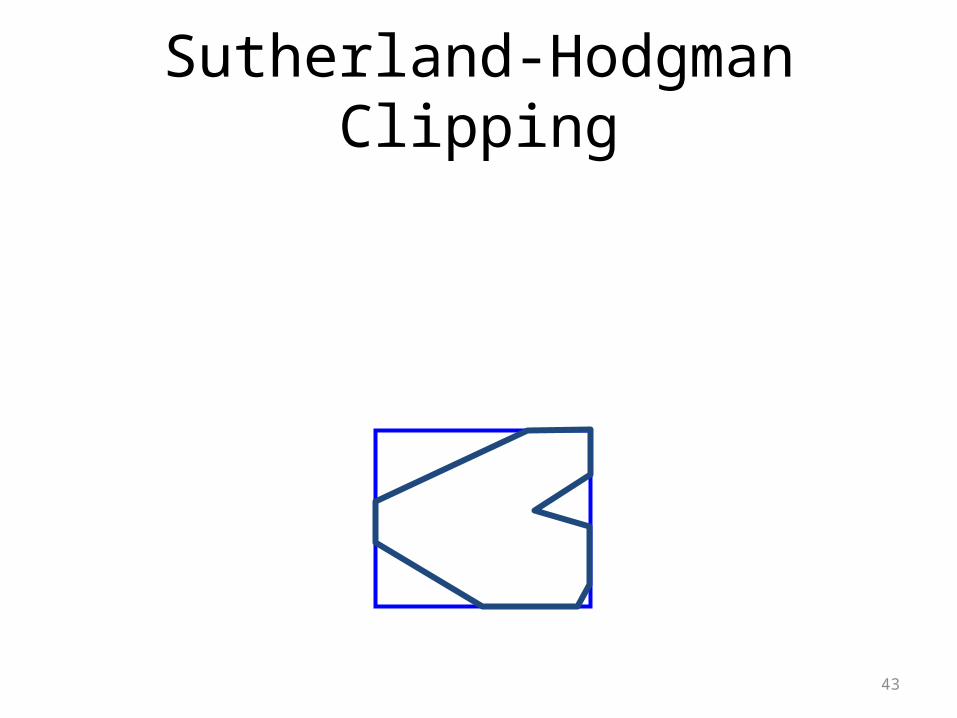
Sutherland-Hodgman Clipping
37
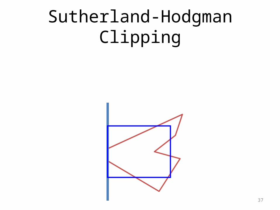
Sutherland-Hodgman Clipping
38
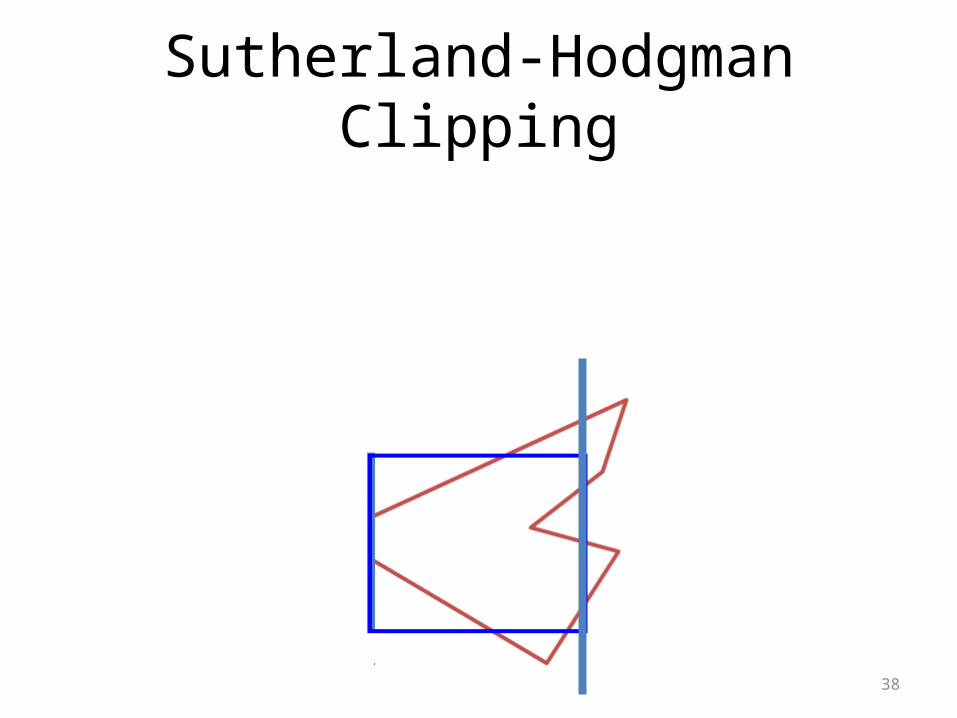
Sutherland-Hodgman Clipping
39
Sutherland-Hodgman Clipping
40
Sutherland-Hodgman Clipping
41
Sutherland-Hodgman Clipping
42
Sutherland-Hodgman Clipping
43
Sutherland-Hodgman Clipping
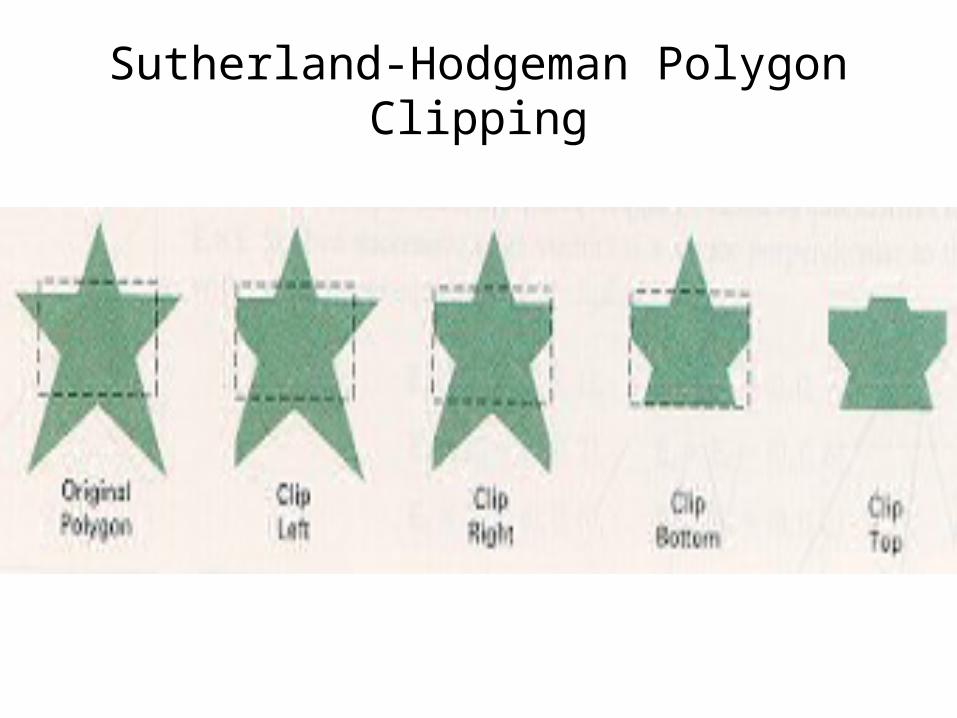
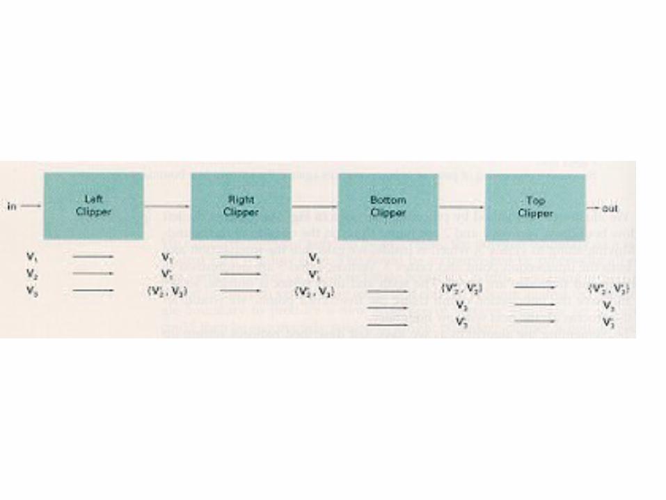
Sutherland-Hodgeman Polygon Clipping
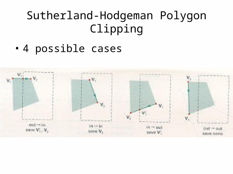
Sutherland-Hodgeman Polygon Clipping
• 4 possible cases
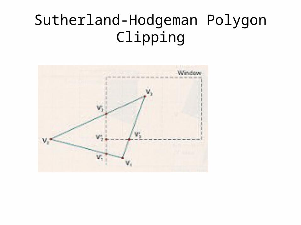
Sutherland-Hodgeman Polygon Clipping
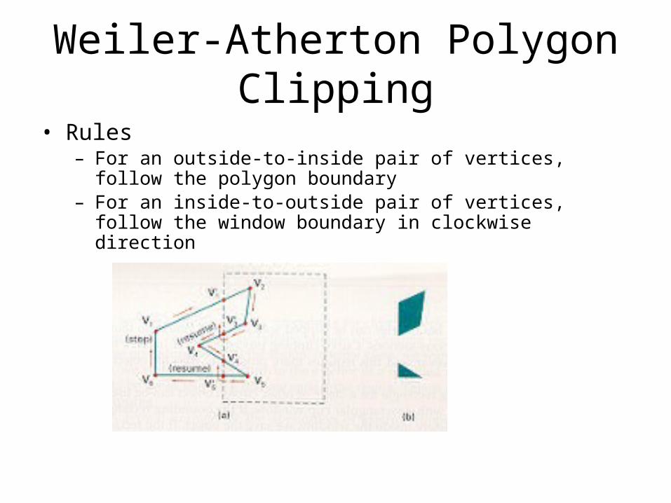
Weiler-Atherton Polygon Clipping• Rules
– For an outside-to-inside pair of vertices, follow the polygon boundary– For an inside-to-outside pair of vertices, follow the window boundary
in clockwise direction
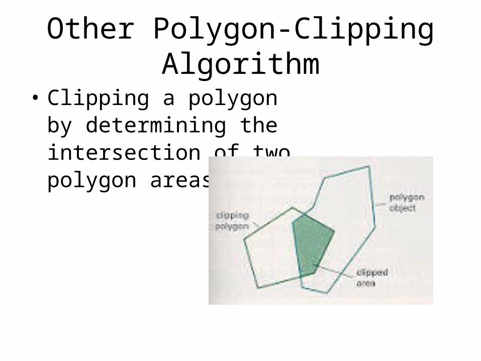
Other Polygon-Clipping Algorithm
• Clipping a polygonby determining theintersection of twopolygon areas
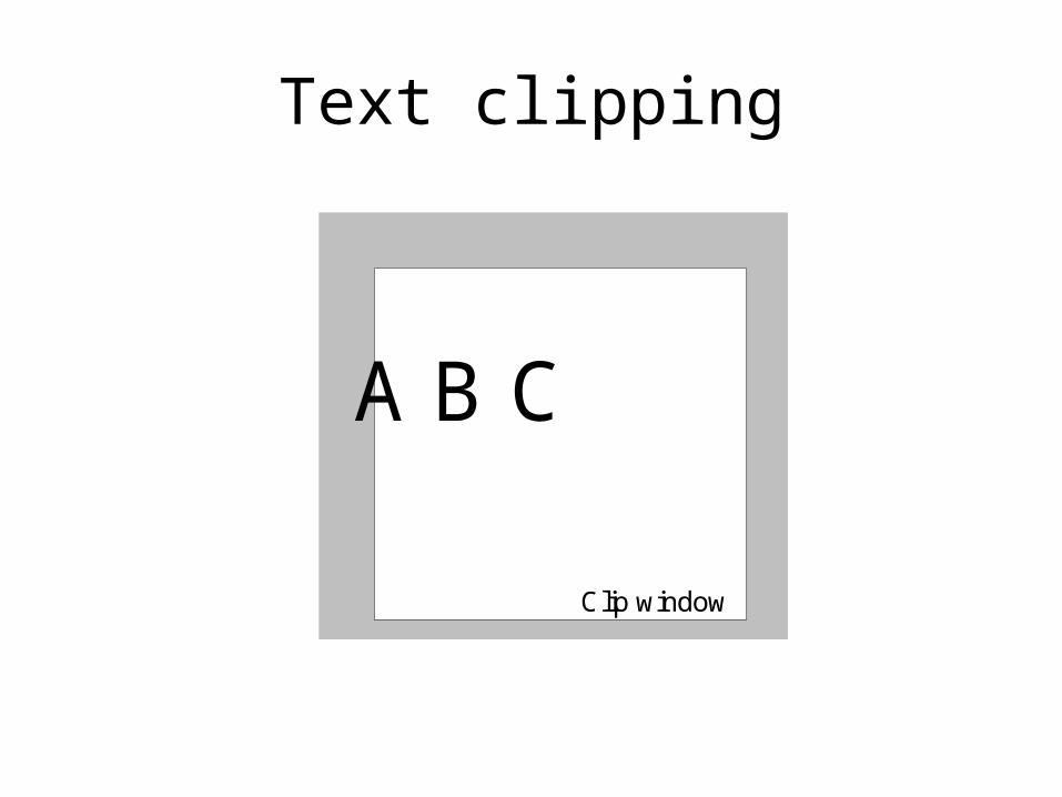
Text clipping
Clip window
A B C
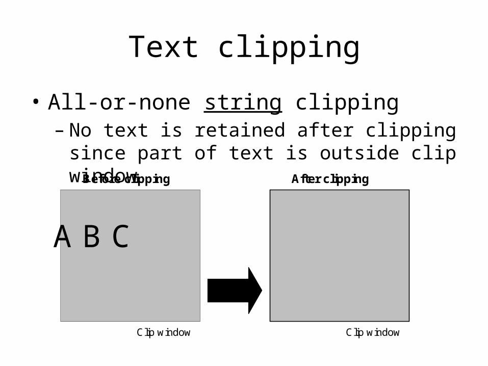
Text clipping
• All-or-none string clipping– No text is retained after clipping
since part of text is outside clip window
Clip window
A B C
Clip window
Before clipping After clipping
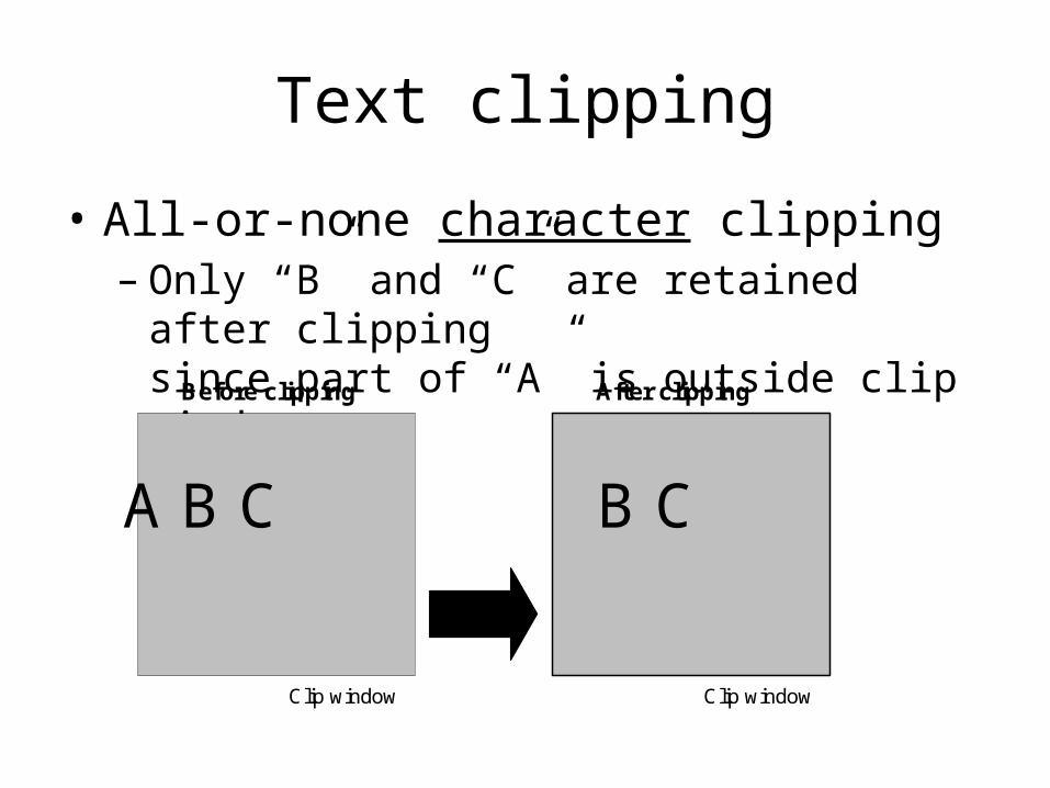
Text clipping
• All-or-none character clipping– Only “B” and “C” are retained after clipping
since part of “A” is outside clip window
Clip window
A B C
Clip window
Before clipping After clipping
B C
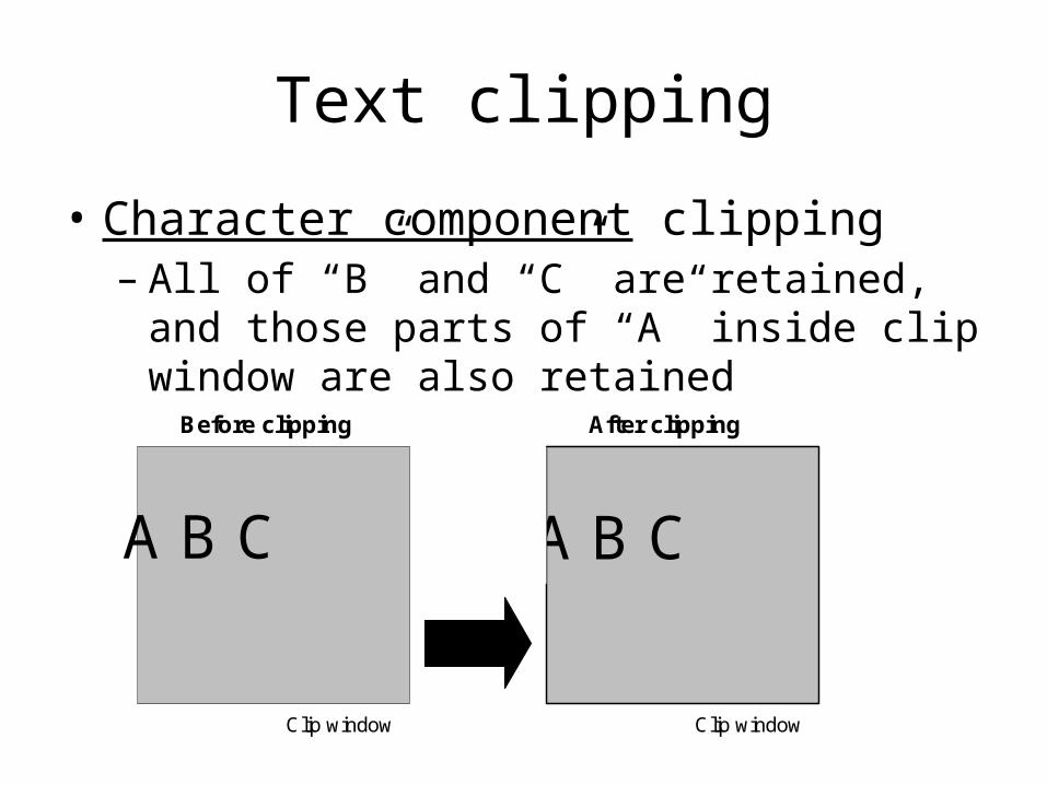
Text clipping
• Character component clipping– All of “B” and “C” are retained, and those parts of
“A” inside clip window are also retained
Clip window
A B C
Clip window
Before clipping After clipping
A B C
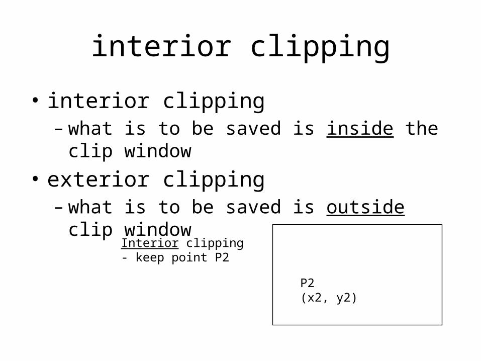
interior clipping
• interior clipping– what is to be saved is inside the clip window
• exterior clipping – what is to be saved is outside clip window
Interior clipping- keep point P2
P2(x2, y2)
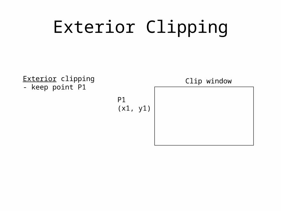
Exterior Clipping
Exterior clipping- keep point P1
Clip window
P1(x1, y1)