Embed Size (px)
Citation preview

9
2 Case Study Vacuum Cleaner: From Vision to Reality
This chapter demonstrates the product development procedure for the envi-ronmental optimisation of a vacuum cleaner that has served as an example product and common reference for the CRC 392. It also presents the re-sults obtained in various steps of product development work and the power of a methodical and holistic product development approach. The im-provements reflect the results from different projects in the run time of the CRC 392.
The development process presented in this chapter was carried out ac-cording to the phases of VDI 2221 clarifying the task, conceptual design, embodiment design and detailed design (VDI 2221 1993). The goal of the process was to environmentally optimise a conventional vacuum cleaner with standard filter bags. The described process is just an excerpt and one possibility for a typical development process. The chapter is structured in such a way that the methods are briefly described first and references for further reading are given. Additionally, results for each method are given afterwards using the vacuum cleaner as an example. Most methods de-scribed in this chapter will be elaborated on in detail throughout the rest of the book.
2.1 Clarifying the Task
The goal of this phase is to clarify the product development task to such a degree that a requirements list can be drawn up. The requirements list de-fines and documents the characteristics of the product. Fig. 2.1 shows dif-ferent information source for deriving the requirements list, which are de-scribed in the following sections.

10 2 Case Study Vacuum Cleaner: From Vision to Reality
Shadowing BenchmarkingChecklists
1
2
3
...
Market questionnaire
Pro
duc
tion
End
-of-
life
Environmentalassessment
Use
?
?
?
?
?
?
?
?
?
?
?
?
Analysis of productsurroundings
Extended requirement list
LC-QFD
LC-QFD: Life Cycle QualityFunction Deployment
1)
1)
Fig. 2.1. Requirements gathered from different sources
Market Questionnaire
In the first step, a market questionnaire is carried out in order to determine what the customer wants and to get a feeling for the customers’ concerns about and interest in the environmental impacts of the product.
Experience shows that the environmentally friendliness of a product it-self is not a guarantee for its success on the market. Therefore, knowledge about the customer, especially in anonymous customer markets, is very important in developing an environmentally friendly and marketable prod-uct (Wiese et al. 2001, see also chapter 5.2).
Questions concerning the environment must be handled with special care since, in most cases, the politically correct answer, and not the real opinion, is given. This problem is increased by the customer’s lack of knowledge about environmental impacts. They are not able to assess prod-ucts’ effects and impacts. Therefore, it is important to scrutinise the cus-tomers’ answers using different interviewing methods and to acquire the real environmental impacts from environmental assessment or expert knowledge.
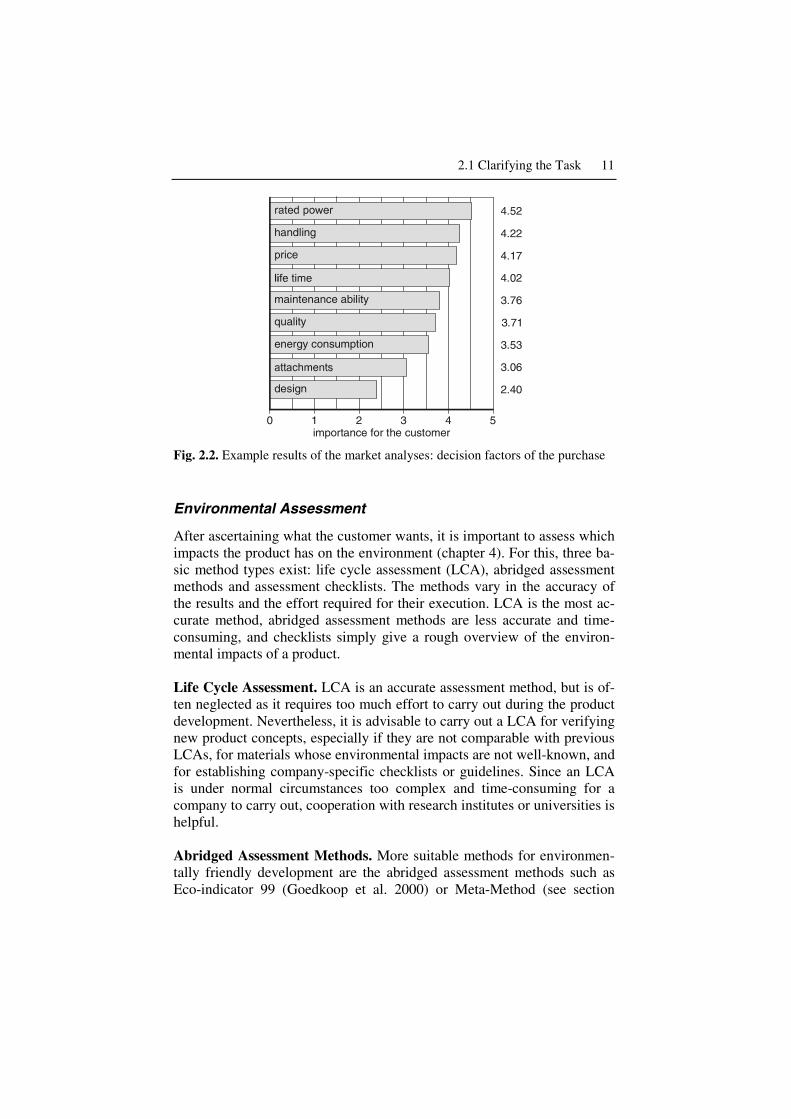
Fig. 2.2 shows that the rated power is the most important buying factor, followed by the price and the handling of the vacuum cleaner.
2.1 Clarifying the Task 11
energy consumption
design
handling
quality
maintenance ability
1 2 3 4 50importance for the customer
4.52
4.22
4.17
4.02
3.76
3.71
3.53
3.06
2.40
Fig. 2.2. Example results of the market analyses: decision factors of the purchase
Environmental Assessment
After ascertaining what the customer wants, it is important to assess which impacts the product has on the environment (chapter 4). For this, three ba-sic method types exist: life cycle assessment (LCA), abridged assessment methods and assessment checklists. The methods vary in the accuracy of the results and the effort required for their execution. LCA is the most ac-curate method, abridged assessment methods are less accurate and time-consuming, and checklists simply give a rough overview of the environ-mental impacts of a product.
Life Cycle Assessment. LCA is an accurate assessment method, but is of-ten neglected as it requires too much effort to carry out during the product development. Nevertheless, it is advisable to carry out a LCA for verifying new product concepts, especially if they are not comparable with previous LCAs, for materials whose environmental impacts are not well-known, and for establishing company-specific checklists or guidelines. Since an LCA is under normal circumstances too complex and time-consuming for a company to carry out, cooperation with research institutes or universities is helpful.
Abridged Assessment Methods. More suitable methods for environmen-tally friendly development are the abridged assessment methods such as Eco-indicator 99 (Goedkoop et al. 2000) or Meta-Method (see section

12 2 Case Study Vacuum Cleaner: From Vision to Reality
4.3.2). For these methods, a specific factor is multiplied by a material weight or energy consumption in order to calculate the environmental im-pact. Despite some criticism from a pure-science point of view, these methods are well-suited for identifying and prioritising a product’s weak-points (Ernzer and Birkhofer 2003a). The advantage of these methods is that they do not require great expertise, time and investment. The main drawbacks include not being able to do a tracing-back and the lack of ac-curacy compared to a LCA following ISO 14040 (1997).
In the CRC 392 an abridged assessment with Eco-indicator 99 for a standard vacuum cleaner using filter bags was applied. The use phase with its electricity consumption was identified as the phase causing the most environmental impacts (Fig. 2.3).
0
50
100
150
200
250
production use disposal
Eco
-indi
cato
r [P
t]
Eco-indicator 99
Fig. 2.3. Environmental impacts of a vacuum cleaner with filter bags
Assessment Checklists. The least accurate yet fastest method of environ-mental assessment are checklists. Examples of such checklists are the MET-Matrix (Material, Emissions, Toxic substances) (Brezet and van Hemel 1997) and ECM (Ecodesign Checklist Method) (Wimmer 1999). In order to increase the efficiency of these checklists, it is possible to create company- or even product-specific checklists like the Kodak Guideline (Betz and Vogel 1996) or the Fast Five from Philips (Meinders 1997).
Analysis of Product Surroundings
One way to better understand the product system and to deduce require-ments is to analyse the product’s surroundings, the interaction with its neighbouring systems, such as other technical products, other people and their surrounding. The interactions are directed from the neighbouring sys-

2.1 Clarifying the Task 13
tem to the product or vice versa. Typical questions for analysing the prod-uct are: − What are the neighbouring systems (products, people, surrounding)? − Which interactions exist between the product and the neighbouring sys-
tems? − Which desired and undesired interactions exist or appear (effect, reper-
cussion, side effect)? − What are the type, duration and frequency of interactions?
The questions must be answered for the operational, stand by and off modes of the product.
By analysing the neighbouring systems of the vacuum cleaner, the prob-lem arose of how the customer determines whether a carpet is clean. This is one reason why the customer cleans certain areas of the carpet more in-tensively as needed. Therefore, a function for indicating when the carpet is clean helps in most cases to reduce the energy consumption during the use phase.
Shadowing
By shadowing users the most important process parameters are identified and user behaviour (Fig. 2.4) is observed.
Optimal behaviour Erroneous behaviour
Real usage behaviour
ProductProduct design
Use process
Environmental impacts
User-product interface
Support Minimize
User
Optimal behaviour Erroneous behaviour
Real usage behaviour
ProductProduct design
Use process
Environmental impacts
User-product interface
Support Minimize
User
Fig. 2.4. User-product interface
The actual observed “real user behaviour” is defined as a superposition of optimal (desired) and erroneous (undesired) behaviour (section 3.3). It can be expressed as a statistical distribution between the two extreme val-ues and the normal behaviour as the expected value (Dannheim et al. 1998).

14 2 Case Study Vacuum Cleaner: From Vision to Reality
The reasons for environmentally erroneous behaviour can be divided into a lack of knowledge about the use process, habitual, unconscious be-haviour, and conscious wrong behaviour. The effects of such false use are usually higher environmental impacts, e.g., increased electricity consump-tion. The effort for carrying out empirical studies is in general high, but the results are very telling. Furthermore, it is possible that by observing only four to five people, up to 80% of process mistakes can be discovered (Virzi 1992).
Environmental impacts caused by erroneous behaviour of the user can be reduced through various strategies (Table 2.1).
Table 2.1. General development strategies for environmental use process optimi-sation (Dannheim 1997)
Type Measure Example Direct measures Moving the system’s border in the product, use
of environmentally friendly working principles Automatic selection of power level
Indirect measures Treatment of negative environmental impacts HEPA Filter after the motor
Demonstrative measures
Feedback loops, instruction manuals, labeling Indicator of current level of dirt on the carpet
HEPA Filter = High Efficiency Particulate Air Filter
Use tests (Fig. 2.5) showed that the vacuum cleaner was not turned off while moving furniture, plants, etc. This resulted in higher energy con-sumption during the use phase. The optimal behaviour would have been to move all hindering objects before starting to vacuum. Therefore, a function for turning off the vacuum cleaner or putting it on stand by while idle is a good opportunity for improving the environmental performance through a direct measure. This improvement option will not be followed up in this chapter, but will be implemented in improved prototype.

2.1 Clarifying the Task 15
Fig. 2.5. Shadowing of users while vacuuming
Checklists
Besides the assessment checklists two general checklists for identifying environmental requirements on products have been developed in the CRC 392 (Fig. 2.6). The first checklist is a general checklist for the development of environmentally friendly products and covers all life stages of a prod-uct. The second checklist is a specific checklist for Design for Recycling (DfR) and consists, besides the checklist, of guidelines and rules. Both checklists are context-sensitive and allow the product developer to browse through the checklist to become inspired by the checkpoints. Using these checklists, various requirements for making the vacuum cleaner conform to the Directive on Waste Electrical and Electronic Equipment (WEEE 2002) were identified. These aspects will be realised in the improved pro-totype, and thus, are not covered in this chapter.

16 2 Case Study Vacuum Cleaner: From Vision to Reality
Checklistenzur Entwicklung
umweltgerechter Produkte
Checklistenzur Entwicklung
umweltgerechter Produkte
Fig. 2.6. Checklists for identifying environmental requirements on products
Benchmarking
Benchmarking consists of comparing competitors’ products to determine how they achieve certain functions and why they use particular assemblies and parts. The overall goal of benchmarking is to combine the best prac-ticed solutions for each sub-function in order to make an “optimal” prod-uct.
First, the overall product function must be compared. This includes an analysis of the electrical energy consumption (operational, stand by and off modes), as well as the consumption of other processes and auxiliary mate-rials. Besides the overall function, the function of each assembly and part must be understood by simply disassembling and analysing the product. After analysing each product, the “cross-product comparison” begins to identify the best solution for each sub-function, evaluating the environ-mental, economic and technical performance. A good approach can be found in Eenhoorn and Stevels (2000).
In the following examples, the focus was on different filter systems and different cleaner heads. For comparing different filter systems a life cycle assessment using SimaPro 4.01 was carried out (Fig. 2.7).
1 SimaPro 4.0 LCA software. PRé Consultants bv, Amersfoort, The Netherlands.

2.1 Clarifying the Task 17
SimaPro 4.0, Eco-indicator 950
100
200
300
400E
co-in
dica
tor
[Pt] Bosch activa 60 (with
brush cleaner head, 700 W)
Bosch activa 60 (withconventional cleaner head, 1100 W)
Dyson DC03 (withcyclone filter, 700 W)
Fig. 2.7. LCA of different systems of vacuum cleaners
Besides this, an abridged assessment was carried out comparing a vac-uum cleaner with a water filter (from the company L’Ecologico) and a conventional filter (from the company Bosch). Because of the high water consumption, particularly for cleaning the dust container, the environ-mental impacts of the water filter are generally much greater (Fig. 2.8).
0
200
400
600
800
L'Ecologico Bosch activa
Eco
-indi
cato
r [P
t]
Fig. 2.8. Eco-indicator 99 of the use phase of vacuum cleaners with water filter (L’Ecologico) in comparison with paper filter (Bosch)
Furthermore, benchmarking for different cleaner heads was carried out. One was a conventional cleaner head and the other was a brush cleaner head. For the benchmarking a carpet with an area of 1 m² was covered with a specific mixture and amount of dust. The dirty carpet was then cleaned with one of the heads and the dust taken in was ascertained. This experi-ment was repeated 12 times. The result was that the brush cleaner head takes in more dust than a conventional cleaner head (Fig. 2.9).
Power input [W]
Inta
ke o
f d
ust
[g
]
Brush cleaner head
Conventional cleaner head
0
100
200
300
400
500
600
700 800 900 1000 1100
Power input [W]
Inta
ke o
f d
ust
[g
]
Brush cleaner head
Conventional cleaner head
0
100
200
300
400
500
600
700 800 900 1000 1100
Fig. 2.9. Intake of dust through different cleaner heads

18 2 Case Study Vacuum Cleaner: From Vision to Reality
Life Cycle Quality Function Deployment (LC-QFD)
Insights to the product, environment and market must be transferred to the requirements list (section 5.4). This is supported by a Life Cycle Quality Function Deployment (LC-QFD), an extension of the conventional QFD (Akao 1990). At first glance, it seems unreasonable to carry out an LC-QFD since the customers’ lack of knowledge concerning environmental impacts results in an uninformed Voice of the Customer (VoC). This ar-gument against the LC-QFD is supported by the tendency of the customer to give the politically correct answer concerning environmental issues rather than his personal opinion (Wiese et al. 2001, see also section 5.2). But still the customers’ opinion about the environment is important since he purchases the product; therefore his opinion must be considered within the customer specification. Furthermore, the environmental expertise must be revealed separately by an expert team or an environmental assessment. Since those customer specifications might be contrary to the environmental impacts it is important to reveal the contradiction using the interrelation matrix (section 5.4.3) in order to consider them during the next develop-ment steps (Dannheim 1999).
Looking at the LC-QFD of the vacuum cleaner identifies the ability to pick up dirt as the most important feature (Fig. 2.10). This is strongly re-lated to the filling capacity of dust bags, filter efficiency, suction power and dust intake; therefore, it positively influences the environmental im-pacts as well as the customer specifications.
product characteristics technical characteristics visu.
charactcontrol / utilization
driv
e
dust
bag
elec
tr.
mat
eria
ls
hous
ing
gene
ral h
andl
ing
suck
ing
actio
n
mai
nten
ance
primary secondary tertiary
pow
er
effic
ienc
y lif
etim
e fil
ling
capa
city
dus
t bag
fil
ter
effic
ienc
y lif
etim
e in
dica
tes
dust
bag
filli
ng
mot
or c
ontr
ol
… … brus
h ac
cess
ibili
ty
filte
r ac
cess
ibili
ty
clea
ner
head
dim
ensi
ons
flexi
ble
pipe
… su
ctio
n po
wer
di
ssip
ated
ene
rgy
dust
inta
ke
… sum
wei
ghte
d
handling at transportation … at vacuuming … sucking power picks up the dirt well picks up a lot of dirt 3 3 9 9 3 3 3 3 9 3 9 92.4 high power 9 1 1 3 3 9 3 64.2 indicator for changing dust bag 1 1 9 9 9 9 52.1 visible cleaning effects 1 3 3 3 1 3 19.3 no unpleasant smell 3 3 22.9 … … environmentally oriented at use air filter 1 3 13.6 little noise 9 1 3 1 22.8 little current 9 9 9 1 3 3 9 3 48.4 ... … design shape/color … cost at buy cheap as possible 3 9 3 1 1 1 9 9 1 3 1 1 54.4 at maintenance maintenance by user 1 3 1 20.7
cust
omer
spe
cific
atio
ns
sum total weighted 66 37 54 30 40 38 47 53 19 12 29 26 60 44 73
Fig. 2.10. LC-QFD of a vacuum cleaner (excerpt)

2.2 Conceptual Design 19
Definition of the Extended Requirements List
For the development of environmentally friendly products it is advisable to extend the conventional requirements list according to Pahl and Beitz (1996) by the functional unit (section 5.4.5). The functional unit is known from the goal definition of a LCA. According to ISO 14041 (1998), the functional unit defines the quantification of performance characteristics. The primary purpose of the functional unit is to provide a reference to which the input and output data are normalised (ISO 14041 1998). Fig. 2.11 shows that, besides the maximal capacity, the user scenario is inte-grated by which the product can be optimised. During the whole project the extended requirements list is continuously being specified and updated.
conv. requirements list extended requirements list functional unit D maximum annual
use: 60 hours
W digital power indicator
D customers function: weekly: vacuuming two times 90 m2
different surfaces
„twice a week cleaning surface of 90 m2 with a total of 32 hours of vacuuming time by 1,100 W over 6,5 years. Changing of dust bags 6 times a year“
D power of vacuum cleaner 1,600 W
D life time: 6.5 years
D possibility to clean different surfaces
D annual use: maximum 60 hours average 32 hours
D life time: 6.5 years W digital power indicator ... ... W emptying vacuum cleaner
6 times a year D power:
maximum 1,600 W average 1,100 W
D = demand W = wish
… …
Fig. 2.11. Extended requirements list including the functional unit (excerpt)
2.2 Conceptual Design
In the conceptual design phase the focus is on three areas of improvement: the cleaner head, the filter system and the problem that the user cleans ar-eas of the carpet too intensively. In order to fulfil the main customer speci-fication “picks up dirt well” the brush cleaner head is systematically varied to improve the dust intake.

20 2 Case Study Vacuum Cleaner: From Vision to Reality
Furthermore, the Theory of Inventive Problem Solving (TRIZ2) is used to find a solution for the contradiction “good filter quality” and “low air resistant” of the filter system. The so-found solution is improved using the Environmental-FMEA from the Ford Motor Company (Schmidt 2001) and finally evaluated.
For finding a solution to the problem of vacuuming carpet areas too of-ten, creativity techniques are used. The type, order and intensity of the methods used vary from problem to problem; thus the processes described below are just one possible example.
Improving the Cleaner Head Applying Systematic Design
Since only two different types of cleaner heads were found during the benchmarking, a more detailed solution field was systematically developed (section 5.5.2).
Morphological matrix In the first step, the function of the cleaner head was divided into the fol-lowing sub-functions: − remove particles − transport particles − move on floor − drive
For each of the sub-functions different solutions were sought using de-sign catalogues, e.g. Roth (2000).
Once solutions are found, they can be structured in classification schemes to systematically add new solutions. The variants thus-found are combined into a complete solution using the morphological matrix (Zwicky 1948).
In Fig. 2.12 the sub-functions of the cleaner head are combined into one complete solution.
2 TRIZ is a Russian method and the abbreviation for Teorija Rezhenija Izober-tatel’skih Zadach

2.2 Conceptual Design 21
sub-solutions sub-functions 1 2 3 4 5 6 remove particles
mechanics pneumatics adhesion electro-statics
acous-tics
physics
transport particles
airflow conveyor belt
tribo-electricity
photo-phoreses
move on floor
sliding surface
rolling body armoured chains
air cushion
drive turbobrush electr./ network
electr./ accu
mechanical user no drive
Fig. 2.12. Combining principal solutions using a morphological matrix
Systematic variation of the working principle of the brush cleaner head. With the knowledge from the morphological matrix, the brushes for the cleaner head must be optimised to better absorb the dust. Therefore, a systematic variation (Pahl and Beitz 1996) of the number of brushes, the type of motion, and the direction of motion were altered and 17 possible solutions found (Fig. 2.13).
number of acting bodies
type of motion
direction ofmotion
i ii iii iv v vi
vii viii ix x xi xii
xviixiii xiv xv xvi
designs ofprinciples
brush
1
x y zi ii iii x y ziv v vi
xvii
2
x y zvii viii ixx y zx xi xii
3
x y zxiii xiv xvy-z
xvi
rot. comb. linear without rot. comb. linear without rot. comb. linear without
rot: rotatingcomb: combined
Fig. 2.13. Systematic variation of a cleaner head with brushes as a working sur-face
Evaluation. Finally, the various solutions for the cleaner head must be evaluated to select the best solution. This was done by a pair-wise com-parison with the result that the standard cleaner head with one brush achieved the highest points due to its simplicity.
22 2 Case Study Vacuum Cleaner: From Vision to Reality
Conceptual Design of the Filter System
TRIZ methodology. TRIZ is especially suitable to solve contradictions revealed by the interrelation matrices of the LC-QFD (section 5.4.3) or by the functional analysis. These contradictions are solved by using one of 40 principles. These principles are arranged in a contradiction matrix and can be accessed via 39 engineering parameters (Altshuller 1999). This meth-odology is implemented in a computer tool called TechOptimizer by In-vention Machine3. The tool consists of the following eight modules: prod-uct analysis, process analysis, effects, principles, prediction, feature transfer and internet assistant.
Functional Analysis Using the Product Analysis Module From clarifying the task it was revealed that a main topic of improvement is the filter system. Therefore a functional analysis using the TRIZ formu-lation technique was carried out for this component. This formulation is easy to use since each part’s function is clearly defined at the beginning. The TRIZ functional model distinguishes between useful and harmful ac-tions which describe the interactions between the functions, objects or tools. Reducing the harmful actions decreases the environmental impacts without sacrificing the quality of the product. Furthermore, reducing the functional model to the minimal functional model first (focus on the main functions), and then adding the auxiliary functions as needed helps to minimise the environmental impacts. The costs and environmental impacts of each added (desired) function, as well as its technical feasibility and marketability, must be carefully screened. Other successful possibilities to vary the function model are shifting the system boundaries, adding or re-moving functions, changing the arrangement of functions, and reducing, simplifying or combining similar functions.
The example in Fig. 2.14 shows that the paper filter bag has the harmful effect “hinder air flow”. The motor protection filter also hinders the air flow and is needed for protecting the motor from the dust, thus eliminating the smell of “burned” dust.
By reducing the harmful action (“hinder air flow”) of the two filters, the energy consumption of the vacuum cleaner during the use phase is de-creased and is, therefore, one goal of the product developer.
3 Invention Machine Corporation, TechOptimizer 3.5 Professional Edition. Bos-ton, Massachusetts

2.2 Conceptual Design 23
paperbag
airflow
generates
generates
generates
generates
smellsunpleasant
pollutes
protects
transports
heats up
transports
generates
transports
transports
transports
keeps
hinders hinders
hinders
engineprotection
filter
coal dustfilter
user
purif
ied
air
residual dustin engine
engine
containerfiltering
impu
rifie
dai
r
underlined functions =desired functions
Fig. 2.14. Function model for the filter system of an existing vacuum cleaner (ex-cerpt)
Solutions Using the Effects Module In order to find a solution for the contradiction “good filter quality” and “low air resistance” of the filter system, the effects module of the Inven-tion Machine was applied. The effects module consists of manifold effects based on an analysis of over 2.5 million patents. Each effect is illustrated by examples. Using this effects and examples database in a workshop, 28 solutions where created for filtering the air flow. One example of an idea was triggered by the example to “Principle 6 – Multifunctionality” (Fig. 2.15).

24 2 Case Study Vacuum Cleaner: From Vision to Reality
abrasive belt with cooling liquid
“endless“ filter tape
US patent Product idea
Fig. 2.15. Tensing an abrasive belt with cooling fluid (on the left side) led to the endless filter tape (on the right side)
The Environmental-FMEA and its Benefit for Improving Solutions. With an Environmental-FMEA, a modification of the conventional FMEA (Failure Mode and Effects Analysis) (Stamatis 1995) with focus on envi-ronmental aspects, it was found that the problem with the above-described filter tape is that the tape is still in the air flow and its air resistance rises with the pollution degree. To minimise the air resistance of the filter tape, it is transported depending on its pollution degree. This is done by measur-ing the pressure difference in front and behind the filter tape with a differ-ence pressure sensor.
The second problem was that the dirty part of the filter tape on the back-side hinders the air flow. Therefore, the design was improved and a filter box was developed (Fig. 2.16).
airflow
Fig. 2.16. Improved filter box after Environmental-FMEA

2.2 Conceptual Design 25
Technical, Environmental and Economic Evaluation. In order to evalu-ate product concepts, the evaluation criteria must be derived from the re-quirements list. It is important that the product is evaluated on environ-mental, technical and economical criteria to develop an overall improved product which is also marketable (section 5.5.3). Since not all criteria are equally important, the criteria must be weighted at the beginning. The re-sults of the LC-QFD can serve as weighting factors. The evaluation proc-ess can be carried out according to VDI 2225 (1998). The results can then be illustrated in a polar diagram (Grüner 2001). Fig. 2.17 shows exemplary evaluation results for the loss of suction of different filter systems as a re-sult of vacuum experiments.
Time [months]
Conventional vacuum cleaner with filter bags
Cyclone and Dyson filter
Cyclone and filter tape
00 11 22 33 44 55 66
15%
5%
75%
Loss of suction
Change offilter bags
Filter tapeis forwarded
Fig. 2.17. Loss of suction of the developed filter system compared existing sys-tems
Dust Sensor Found by Creativity Techniques in Conceptual Design
Creativity techniques, such as brainstorming or method 635 (Pahl and Beitz 1996), can be carried out in moderated team sessions to find new so-lutions for different functions. Brainstorming is used if the problem is nei-ther specific nor strictly defined. The thus-found solutions are vague and not yet detailed. The method 635 supports the successive generation of ideas based on the ideas of other participants. It is used when more de-tailed solutions are sought and the problem is more clearly defined.
In the case of the vacuum cleaner a brainstorming session was carried out for the problem “cleaning carpet areas too intensive”. The solution found during brainstorming was to integrate a sensor in the suction pipe which measures the amount of dust going through the pipe to able to indi-cate the cleanness of the floor.
26 2 Case Study Vacuum Cleaner: From Vision to Reality
2.3 Embodiment and Detailed Design
The embodiment and detailed design phases are grouped together since the methods and tools used during these phases are interchangeable. Embodi-ment design leads from the principal solution to a definitive layout. De-tailed design ends in the product documentation. For this detailing process, the design rules and guidelines, the creativity techniques, the morphologi-cal matrix, and the evaluation method described before are also helpful. For the vacuum cleaner, these two phases were roughly carried out in order to develop the prototype. Currently these phases are being carried out in detail together with industrial designer in order to put the finishing touches on the prototype.
The Role of Design Rules and Guidelines
Throughout the whole product development process, design rules and guidelines exist to guide the product developer. Different rules and guide-lines are assigned to each strategy, which can be followed. A good set of measures, design rules and guidelines can be found in the computer-based ECODESIGN PILOT (Wimmer and Züst 2001).
Material Selection Tools
Material selection tools support the product developer in choosing materi-als with low environmental impact. The material selection is, besides the consumption of process and auxiliary materials in the use phase, the most influential factor for most environmental impacts (Atik 2001). Therefore, it is necessary to pay special attention to the material selection. One of the most comprehensive databases with material characteristics and environ-mental impact data is the IdeMat database4. A good addition to the IdeMat database is the Campus database, which has detailed information about the characteristics of plastics of different producers5.
Evaluation of User Behaviour
In order to develop a product feasibility study, a prototype must be built. Since new solutions are developed for the user (consumer) it is further ad-visable to carry out an evaluation of user behaviour (Sauer et al. 2001).
4 IdeMat, TU Delft, Design for Sustainability Program, Delft, The Netherlands 5CAMPUS®, Computer Aided Material Preselection by Uniform Standards,
CWFG mbH, Frankfurt/Main, 1991

2.4 Result: The Vacuum Cleaner Prototype 27
The aim is to assess the user’s acceptance of the new solution and the real user behaviour.
ecoDesign Workbench of CRC 392
A powerful tool for supporting product development during the detailed design is the ecoDesign Workbench of the CRC 392 (Fig. 2.18). The ecoDesign Workbench enables the product developer to carry out an envi-ronmental assessment during its detailed design phase in a CAD system. A first prototype was implemented and evaluated using an electric kettle. Based on this evaluation the prototype was improved and evaluated using an impeller fan of an electric heater (Felsing et al. 2004a). The results show that the ecoDesign Workbench is a suitable tool to efficiently and ef-fectively support the product developer during this design phase.
informationsystem
productmodelling
life-cycleassessment
processmodelling
informationsystem
productmodellingproduct
modelling
life-cycleassessment
processmodelling
Fig. 2.18. ecoDesign Workbench of CRC 392
28 2 Case Study Vacuum Cleaner: From Vision to Reality
2.4 Result: The Vacuum Cleaner Prototype
As a first result of the product development process, the improved solution for the brush cleaner head, the filter system and the dust sensor in the suc-tion pipe are described below in whole. At present, all improvements are realised in one prototype.
Brush Cleaner Head to Reduce Suction Losses by Enclosed Air Canals
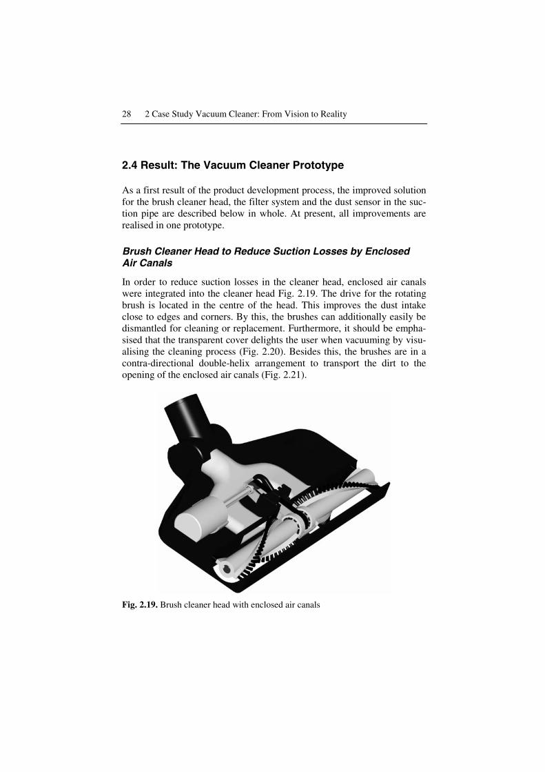
In order to reduce suction losses in the cleaner head, enclosed air canals were integrated into the cleaner head Fig. 2.19. The drive for the rotating brush is located in the centre of the head. This improves the dust intake close to edges and corners. By this, the brushes can additionally easily be dismantled for cleaning or replacement. Furthermore, it should be empha-sised that the transparent cover delights the user when vacuuming by visu-alising the cleaning process (Fig. 2.20). Besides this, the brushes are in a contra-directional double-helix arrangement to transport the dirt to the opening of the enclosed air canals (Fig. 2.21).
Fig. 2.19. Brush cleaner head with enclosed air canals

2.4 Result: The Vacuum Cleaner Prototype 29
Fig. 2.20. Brush cleaner head with transparent cover
Fig. 2.21. Exploded view of the brush cleaner head showing the contra-directional double-helix arrangement of the brushes
30 2 Case Study Vacuum Cleaner: From Vision to Reality
Filter System to Minimise the Loss of Suction
One aim in determining the conceptual design was to minimise the loss of suction due to clogged dust bags and fine-mesh filters. This goal should be reached independently of the user’s behaviour.
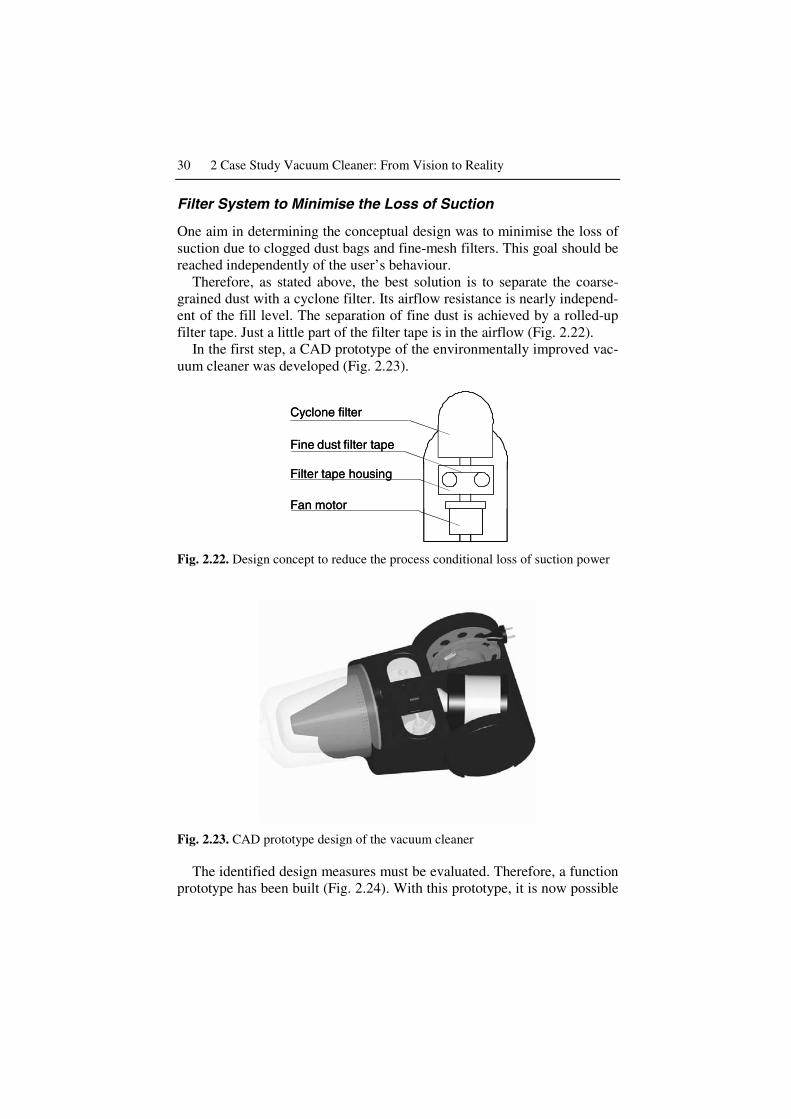
Therefore, as stated above, the best solution is to separate the coarse-grained dust with a cyclone filter. Its airflow resistance is nearly independ-ent of the fill level. The separation of fine dust is achieved by a rolled-up filter tape. Just a little part of the filter tape is in the airflow (Fig. 2.22).
In the first step, a CAD prototype of the environmentally improved vac-uum cleaner was developed (Fig. 2.23).
Cyclone filter
Filter tape housing
Fan motor
Fine dust filter tape
Cyclone filter
Filter tape housing
Fan motor
Fine dust filter tape
Fig. 2.22. Design concept to reduce the process conditional loss of suction power
Fig. 2.23. CAD prototype design of the vacuum cleaner
The identified design measures must be evaluated. Therefore, a function prototype has been built (Fig. 2.24). With this prototype, it is now possible

2.4 Result: The Vacuum Cleaner Prototype 31
to test the functionality of the filter system. For this purpose, vacuum ex-periments were being carried out. It was found out that it is possible to in-tegrate enough filter tape in the housing to make the tape lasts the whole life time of the vacuum cleaner. Thus, the customer does not need to change the tape and to spend money on new filter tapes.
Fig. 2.24. Function prototype of the vacuum cleaner
The filter tape has been improved in such a way that a completely me-chanical solution was found. This includes the measurement of the differ-ence pressure before and after the tape and the forwarding of the tape (Fig. 2.25). The implementation of this improved filter tape will be carried out in an interdisciplinary team of product developers and industrial de-signers.

32 2 Case Study Vacuum Cleaner: From Vision to Reality
Fig. 2.25. Function prototype of the filter box
Dust Sensor to Support Users during Vacuuming
To support the user in vacuuming areas only once, a function to measure the cleanness of the floor is implemented (Weger et al. 2001). This func-tion is based on an infrared particle sensor in the tube close to the cleaner head (Fig. 2.26).
This could support the user in saving energy due to the availability of accurate information about the cleanness of the floor. The function consists of a feedback device that informs the user of current cleanness levels. Based on this information, the user can rapidly and precisely identify dirty floor areas and respond immediately by moving forwards.
Luminescent diode
Sensor accommodation
Photovoltaic cell
Fig. 2.26. Arrangement of the measuring set

2.5 Conclusions 33
A first prototype of a feedback device has been developed. A blinking red light indicates that dust particles are passing through the tube. The sig-nal turns green if the amount of dust particles remains below a certain level. The light is located on top of the cleaner head, and therefore, is eas-ily noticeable by the user (Fig. 2.27).
save time!
stilldirty!
finished!
greenred
Fig. 2.27. Arrangement of the user feedback device at the cleaner head
The development of the feedback device needs to be carefully consid-ered since design choices (e.g., acoustic, visual feedback, threshold value) may heavily influence user behaviour. Therefore, it is necessary to carry out empirical tests to ensure that pre-defined performance standards are met and no undesired side-effects crop up.
It was predicted that environmental impacts (e.g., due to increased en-ergy consumption) can be reduced by increasing the user support. Based on the empirical tests, it will be determined to which extent this kind of feedback device reduces the environmental impact.
2.5 Conclusions
Throughout the systematic product development, it was possible to de-velop an environmentally friendly vacuum cleaner, which was also techni-cally improved and should have a high marketability. At the time of print, the finishing touches were being put on the prototype of the vacuum

34 2 Case Study Vacuum Cleaner: From Vision to Reality
cleaner for further improvement. This project is executed in cooperation with industrial designers to give the environmentally friendly and market-able vacuum cleaner the cutting edge.
It is important to understand that for many methods and tools besides the results, the way to the results reveals new insights. Therefore, working in interdisciplinary product development teams and using group methods and tools are key success factors for the development of environmentally friendly products.

http://www.springer.com/978-1-85233-903-6